
NUMERICAL SIMULATION OF BPF PRESSURE PULSATION FIELD IN CENTRIFUGAL … · 2016-01-10 · NUMERICAL...
22
Serguei Timouchev is Director General with InteRe Ltd., in Moscow, Russia. He began his career in 1980 with the Buran space program, and in 1992 he began work within Moscow Aviation Institute for the Arianne-Vulcain project. Dr. Timouchev was involved in many experimental and computational studies in pressure pulsation and vibration in centrifugal turbopump units of liquid propellant rocket engines, including reduction of pressure pulsation and vibration caused by cavitation, reverse flows, and acoustical amplification. In 1986, he proposed an original method for numerical modeling of pressure pulsation in centrifugal machines. For the last decade, he has worked on the problem of computational prediction of pressure pulsation and reduction of vibration and noise in centrifugal pumps and ventilators. Dr. Timouchev graduated from Moscow Aviation Institute (1978) and later received his Ph.D. degree. He is author and coauthor of 30 technical papers and is an affiliate member of the INCE/Europe. Jean Tourret is Head of the Acoustical Department, Vibration and Thermal Engineering Department of CETIM, in Cedex, France. He has been involved in the development of vectorial sound intensity, which led to the organization of four international meetings in France from 1981 to 1991. He has been active in studies on noise from hydraulic machines including pumps since 1975. Mr. Tourret developed an anechoic liquid terminator to measure pressure pulsations in piping systems and specific methodologies to visualize acoustic wave generation inside impellers and volutes. He organized the first international meeting on fan noise in Senlis, France, in 1992, and he coorganized the First International Meeting on Pump Noise and Vibration held in Clamart, France, in 1993. Mr. Tourret graduated from the Institut Polytechnique of Grenoble (1971). He is Vice President of the International Institute of Noise Control Engineering, President of INCE/Europe, and author and coauthor of over 40 technical papers. ABSTRACT There is a close link between the pressure pulsation in the pump working cavity and its vibration and noise level. Due to a current trend in increasing rotation speed and power, the problem of noise, vibration, and pressure pulsation in centrifugal pumps becomes a more urgent question. Usually the level of tone spectrum components determines the pump vibration and noise characteris- tics, and mainly these are blade-passing frequencies (BPF). They result from nonstationary hydrodynamic interaction between the impeller flow and pump casing. The method for computation of BPF pressure pulsations in the working cavity of a centrifugal pump is based on a representation of nonstationary motion of a compressible medium as a combination of acoustical waves and pseudosound perturbations. INTRODUCTION—DESCRIPTION OF THE PROBLEM OF HYDRAULIC VIBRATION IN CENTRIFUGAL PUMPS Main Noise and Vibration Sources in Centrifugal Pumps It is well known that the principal noise and vibration sources in a well-balanced centrifugal pump are of a hydrodynamic nature. There is a close link between the pressure pulsation in the pump working cavity and its noise and vibration level. It is possible to subdivide the nonstationary hydrodynamic phenomena in the working cavity of a pump in two groups outlined below. • Hydrodynamic interaction between the impeller flow and the volute casing • Vortex flow They are accompanied by cavitation phenomena that can act as a separate source of hydraulic noise and may provoke amplification of unsteadiness of the two groups mentioned. The first type of pressure pulsation that causes tone noise and vibration is the subject of this lecture. Relationship Between Pressure Pulsation, Vibration, Deformation, and Noise The conclusions drawn from the works mentioned above indicate a close link between the pressure pulsations in the pump working cavity and its vibration and noise. The existence of intense pressure pulsations is characteristic of all types of centrifugal pumps. Under certain conditions pressure 85 NUMERICAL SIMULATION OF BPF PRESSURE PULSATION FIELD IN CENTRIFUGAL PUMPS by Serguei Timouchev Director General InteRe Ltd. Moscow, Russia and Jean Tourret Head of Acoustical Department CETIM Cedex, France
Transcript of NUMERICAL SIMULATION OF BPF PRESSURE PULSATION FIELD IN CENTRIFUGAL … · 2016-01-10 · NUMERICAL...

Serguei Timouchev is Director Generalwith InteRe Ltd., in Moscow, Russia. Hebegan his career in 1980 with the Buranspace program, and in 1992 he began workwithin Moscow Aviation Institute for theArianne-Vulcain project. Dr. Timouchevwas involved in many experimental andcomputational studies in pressure pulsationand vibration in centrifugal turbopumpunits of liquid propellant rocket engines,including reduction of pressure pulsation
and vibration caused by cavitation, reverse flows, and acousticalamplification. In 1986, he proposed an original method fornumerical modeling of pressure pulsation in centrifugal machines.For the last decade, he has worked on the problem ofcomputational prediction of pressure pulsation and reduction ofvibration and noise in centrifugal pumps and ventilators.
Dr. Timouchev graduated from Moscow Aviation Institute (1978)and later received his Ph.D. degree. He is author and coauthor of30 technical papers and is an affiliate member of the INCE/Europe.
Jean Tourret is Head of the AcousticalDepartment, Vibration and ThermalEngineering Department of CETIM, inCedex, France. He has been involved in thedevelopment of vectorial sound intensity,which led to the organization of fourinternational meetings in France from 1981to 1991. He has been active in studies onnoise from hydraulic machines includingpumps since 1975. Mr. Tourret developedan anechoic liquid terminator to measure
pressure pulsations in piping systems and specific methodologiesto visualize acoustic wave generation inside impellers and volutes.He organized the first international meeting on fan noise in Senlis,France, in 1992, and he coorganized the First InternationalMeeting on Pump Noise and Vibration held in Clamart, France, in1993.
Mr. Tourret graduated from the Institut Polytechnique ofGrenoble (1971). He is Vice President of the International Instituteof Noise Control Engineering, President of INCE/Europe, andauthor and coauthor of over 40 technical papers.
ABSTRACT
There is a close link between the pressure pulsation in the pumpworking cavity and its vibration and noise level. Due to a currenttrend in increasing rotation speed and power, the problem of noise,vibration, and pressure pulsation in centrifugal pumps becomes amore urgent question. Usually the level of tone spectrumcomponents determines the pump vibration and noise characteris-tics, and mainly these are blade-passing frequencies (BPF). Theyresult from nonstationary hydrodynamic interaction between theimpeller flow and pump casing. The method for computation ofBPF pressure pulsations in the working cavity of a centrifugalpump is based on a representation of nonstationary motion of acompressible medium as a combination of acoustical waves andpseudosound perturbations.
INTRODUCTION—DESCRIPTIONOF THE PROBLEM OF HYDRAULICVIBRATION IN CENTRIFUGAL PUMPS
Main Noise and Vibration Sources in Centrifugal Pumps
It is well known that the principal noise and vibration sources ina well-balanced centrifugal pump are of a hydrodynamic nature.There is a close link between the pressure pulsation in the pumpworking cavity and its noise and vibration level.
It is possible to subdivide the nonstationary hydrodynamicphenomena in the working cavity of a pump in two groups outlinedbelow.
• Hydrodynamic interaction between the impeller flow and thevolute casing
• Vortex flow
They are accompanied by cavitation phenomena that can act as aseparate source of hydraulic noise and may provoke amplificationof unsteadiness of the two groups mentioned.
The first type of pressure pulsation that causes tone noise andvibration is the subject of this lecture.
Relationship Between Pressure Pulsation,Vibration, Deformation, and Noise
The conclusions drawn from the works mentioned aboveindicate a close link between the pressure pulsations in the pumpworking cavity and its vibration and noise.
The existence of intense pressure pulsations is characteristic ofall types of centrifugal pumps. Under certain conditions pressure
85
NUMERICAL SIMULATION OF BPFPRESSURE PULSATION FIELD IN CENTRIFUGAL PUMPS
bySerguei Timouchev
Director General
InteRe Ltd.
Moscow, Russia
andJean Tourret
Head of Acoustical Department
CETIM
Cedex, France
pulsations in the working cavity, e.g., in the volute casing, canachieve values dangerous to the pump integrity.
The study of pressure pulsations in the working cavity ofcentrifugal pumps gives information on nonstationary loads actingon the pump components—diffuser vanes, impeller blades, volutecasing, outlet pipe. When measuring the dynamic load on theleading edges of diffuser vanes of a centrifugal pump by straingauges, it was found that in the range of delivery 0.6 to 1.0 from itsoptimum value the dynamic load is directly proportional to theamplitude of pressure pulsations.
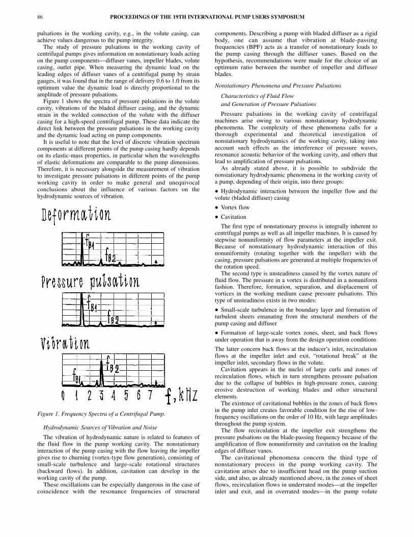
Figure 1 shows the spectra of pressure pulsations in the volutecavity, vibrations of the bladed diffuser casing, and the dynamicstrain in the welded connection of the volute with the diffusercasing for a high-speed centrifugal pump. These data indicate thedirect link between the pressure pulsations in the working cavityand the dynamic load acting on pump components.
It is useful to note that the level of discrete vibration spectrumcomponents at different points of the pump casing hardly dependson its elastic-mass properties, in particular when the wavelengthsof elastic deformations are comparable to the pump dimensions.Therefore, it is necessary alongside the measurement of vibrationto investigate pressure pulsations in different points of the pumpworking cavity in order to make general and unequivocalconclusions about the influence of various factors on thehydrodynamic sources of vibration.
Figure 1. Frequency Spectra of a Centrifugal Pump.
Hydrodynamic Sources of Vibration and Noise
The vibration of hydrodynamic nature is related to features ofthe fluid flow in the pump working cavity. The nonstationaryinteraction of the pump casing with the flow leaving the impellergives rise to churning (vortex-type flow generation), consisting ofsmall-scale turbulence and large-scale rotational structures(backward flows). In addition, cavitation can develop in theworking cavity of the pump.
These oscillations can be especially dangerous in the case ofcoincidence with the resonance frequencies of structural
components. Describing a pump with bladed diffuser as a rigidbody, one can assume that vibration at blade-passingfrequencies (BPF) acts as a transfer of nonstationary loads tothe pump casing through the diffuser vanes. Based on thehypothesis, recommendations were made for the choice of anoptimum ratio between the number of impeller and diffuserblades.
Nonstationary Phenomena and Pressure Pulsations
Characteristics of Fluid Flowand Generation of Pressure Pulsations
Pressure pulsations in the working cavity of centrifugalmachines arise owing to various nonstationary hydrodynamicphenomena. The complexity of these phenomena calls for athorough experimental and theoretical investigation ofnonstationary hydrodynamics of the working cavity, taking intoaccount such effects as the interference of pressure waves,resonance acoustic behavior of the working cavity, and others thatlead to amplification of pressure pulsations.
As already stated above, it is possible to subdivide thenonstationary hydrodynamic phenomena in the working cavity ofa pump, depending of their origin, into three groups:
• Hydrodynamic interaction between the impeller flow and thevolute (bladed diffuser) casing
• Vortex flow
• Cavitation
The first type of nonstationary process is integrally inherent tocentrifugal pumps as well as all impeller machines. It is caused bystepwise nonuniformity of flow parameters at the impeller exit.Because of nonstationary hydrodynamic interaction of thisnonuniformity (rotating together with the impeller) with thecasing, pressure pulsations are generated at multiple frequencies ofthe rotation speed.
The second type is unsteadiness caused by the vortex nature offluid flow. The pressure in a vortex is distributed in a nonuniformfashion. Therefore, formation, separation, and displacement ofvortices in the working medium cause pressure pulsations. Thistype of unsteadiness exists in two modes:
• Small-scale turbulence in the boundary layer and formation ofturbulent sheets emanating from the structural members of thepump casing and diffuser
• Formation of large-scale vortex zones, sheet, and back flowsunder operation that is away from the design operation conditions
The latter concern back flows at the inducer’s inlet, recirculationflows at the impeller inlet and exit, “rotational break” at theimpeller inlet, secondary flows in the volute.
Cavitation appears in the nuclei of large curls and zones ofrecirculation flows, which in turn strengthens pressure pulsationdue to the collapse of bubbles in high-pressure zones, causingerosive destruction of working blades and other structuralelements.
The existence of cavitational bubbles in the zones of back flowsin the pump inlet creates favorable condition for the rise of low-frequency oscillations on the order of 10 Hz, with large amplitudesthroughout the pump system.
The flow recirculation at the impeller exit strengthens thepressure pulsations on the blade-passing frequency because of theamplification of flow nonuniformity and cavitation on the leadingedges of diffuser vanes.
The cavitational phenomena concern the third type ofnonstationary process in the pump working cavity. Thecavitation arises due to insufficient head on the pump suctionside, and also, as already mentioned above, in the zones of sheetflows, recirculation flows in underrated modes—at the impellerinlet and exit, and in overrated modes—in the pump volute
PROCEEDINGS OF THE 19TH INTERNATIONAL PUMP USERS SYMPOSIUM86

NUMERICAL SIMULATION OF BPF PRESSURE PULSATION FIELD IN CENTRIFUGAL PUMPS 87
casing. Cavitation is an independent source of nonstationarypressure pulsations and vibration. Besides, cavitation in theimpeller blade channels strengthens BPF oscillations owing toan increase of the flow pitch nonuniformity. Such a conclusionis confirmed by the outcome of visual studies of cavitatingpumps.
Noise, Vibration, and Pressure Pulsation Spectra
The noise, vibration, and pressure pulsation spectra ofcentrifugal pumps are represented by a broadband noise to whichclearly discernible discrete components are superimposed(generally, they are blade-passing frequencies). The level of thesetone components mainly determines the pump noise and vibrationcharacteristics, as the tonal noise is very uncomfortable to thehuman ear. These oscillations may also be harmful in the case ofcoincidence with the resonance frequencies of structuralcomponents or acoustical resonance of the pump working cavity.The last phenomenon is very possible for high-speed pumps oflarge dimension.
The small-scale vortices generate turbulent noise, which gives abroadband component of low intensity in the full frequency rangeof the spectra of pressure pulsation, noise, and vibration.
Large-scale vortex structures create high-level weakly correlatedimpulses of pressure. In the spectra of pressure pulsation, noise,and vibration, this is presented as a sharp increase of the broadbandcomponent in the zone of low and medium frequencies (called thepedestal).
Pressure Pulsations at Multiple Rotation Frequencies
Examples of typical spectra of pressure pulsations and vibrationof a centrifugal pump are shown in Figures 2 and 3. They arecharacterized by a broadband noise component to which discretecomponents are superimposed. The frequencies of discretecomponents are multiples of the rotation frequency.
Figure 2. Spectra of Pressure Pulsations in the Volute (Above) andin the Diffuser Vane Channel (Below) of a Centrifugal Pump.
Figure 3. Typical Vibration Spectrum of a Centrifugal Pump.
• Pressure pulsations at BPF
Studies of centrifugal pumps show that, as a rule, the discreteBPF component and its harmonics dominate in spectra of pressurepulsations and vibrations in the design operation mode. BPF isdefined by the formula:
(1)
where:fr = Frequency of rotation, Hzz = Number of impeller or inducer bladesk = Harmonic order
An investigation into the mechanisms of generation of pressurepulsations and its numerical modeling requires studies of the natureof the flow in the impeller exit zone. Increased attention in Russiaand abroad has been paid during the last 40 years to experimental andcomputational studies of the flow in centrifugal machines. In-depthstudies of the flow parameters at the impeller outlet of centrifugalpumps, compressors, and ventilators confirm that the flow in bladechannels near the impeller exit can be subdivided in two areas—ahigh-energy jet component and a low-energy zone of vortex sheets.Such flow characteristics induce an essential pitch nonuniformity ofrelative and absolute velocities and flow angles, as the low-energyzone adheres to the suction side of the blade. On the impeller exit, thepitch distribution of the static pressure is close to uniform; therefore,the difference in total fluid energy between the two mainly originatesfrom the dynamic part of the fluid energy. Due to the heterogeneityof flow in the presence of the passing impeller blades, a pressurevariation in each channel of the diffuser or in the volute takes place.
Especially sharp flow variation occurs near the leading edges ofdiffuser vanes and volute tongue. Consequently, great attentionmust be given to the choice of an optimum radial gap between theimpeller and diffuser vanes or volute tongue.
As specified previously, the separation of nonstationary pumpprocesses is conditional on three types. Therefore, the formation ofcurls and cavitation in blade channels of the impeller strengthensthe pitch nonuniformity of flow and promotes amplification of BPFpulsation. The recirculation of flow on the impeller outlet alsostrengthens the unsteadiness of the first type; because it is knownthat the same design measures reduce BPF pressure pulsation andrecirculation of flow at the impeller outlet. Flow separations andcavitation in pump casing can be in turn periodically initiated bythe passage of impeller blades.
Thus, the unsteadiness of the first type (hydrodynamicinteraction between the impeller flow and the casing) takes aspecial place in the vibration character of a centrifugal pump.Determination of its vibration and noise in the optimum operationmode is the most important object of study for reduction of BPFpressure pulsations and vibration and increase of lifetime withpreservation of high power characteristics.
• Pressure pulsations at the rotation frequency
Manufacturing deviations of impeller geometry with respect tothe angular symmetry and the asymmetrical disposition of theimpeller and inducer blades give rise to pressure pulsations at therotation frequency and its higher harmonics. This is explained bytangential nonuniformity in the distribution of flow parameters atthe impeller exit circle. Rotating together with the impeller, thisnonuniformity excites oscillations with the rotation frequency inthe pump volute or diffuser vane channels.
• Combined components in the pressure pulsation spectra of acentrifugal pump with inducer
An essential role in the formation of the flow pitch nonuniformityat the impeller outlet belongs to Coriolis and centrifugal forces. Itresults in a nonlinear character of interaction of the initialnonuniformity of the flow, caused by the inducer, with an irregularflow in the impeller. In other words, pitch nonuniformity of the flow
f k z fr=
in the impeller channels is modulated by the “inducer” pitchnonuniformity. The frequencies of this modulation are:
(2)
where za is the number of inducer blades.For example, in a centrifugal pump with a double-bladed
centrifugal impeller having seven main and seven additional shortblades and three-blade inducer in the spectra of pressure pulsations(refer to Figure 2), the combined frequencies account for 4, 10, 11,17, 18, and 24 multiples of the rotation speed.
Considering this, it is possible to shape the spectra of pressurepulsations and vibration of the centrifugal pump by design. Theapplication of a centrifugal impeller with six main blades instead ofseven in the same pump eliminates such discrete components as 4 fr.
• Possibilities of diagnosing pump operability by measuringpressure pulsations
The pressure pulsations in the pump working cavity can be auseful indication for the diagnosis of the availability of the unit aswell as of dangerous operational modes—cavitation in particular.While the signal coming from the vibration transducer isinfluenced by mechanical properties of the installation setup, thepressure pulsation sensor immediately reflects any change ofphysical parameters of the working medium.
Experimental and computational studies have shown thepossibilities of diagnosing centrifugal pump impeller breakage andapproaching critical cavitational operation mode of axial pumps.
Dependence of Pressure Pulsations, Vibration,and Noise on Operational Mode and Design Features
Influence of Flow Rate
As a rule, the peak-to-peak level of the total signal of pressurepulsations is at minimum near the optimum delivery and that itconsiderably increased at flow rates that deviate from thisoptimum. The minimum of pressure pulsations does notnecessarily precisely coincide with the optimum point of the powerperformance of the pump. In the range of flow rates of about 0.8 to1.1 of the BEP value, the level of pulsations is low. By decreasingthe flow rate, the pressure pulsation level rises due to theamplification of pitch nonuniformity of the outlet impeller flowdue to the contraction of the zone of active flow and theamplification of vorticity. A number of works have shown that, atlower flow rates, the low-frequency component of pulsationspectrum increases.
In conditions of insufficient suction head at low flow rates, theprobability of initiation of low-frequency auto-oscillations of thehydraulic circuit is increased.
At higher flow rates, the pressure pulsations increase due toseparation of flow and development of cavitation on diffuser vanesnear the volute throat. With the flow rate increasing, the total levelof pressure pulsation can also rise at the expense of BPFpulsations.
Pressure Pulsations in VariousElements of the Hydraulic Circuit
The indicated features of the change of pressure pulsation due tothe flow rate variation are characteristic of different points of thehydraulic circuit of centrifugal pumps. The pressure pulsationswere investigated at the input of a pump, in the channels of acentrifugal impeller, at the impeller outlet, in the vanelessdiffusers, in the bladed diffuser channels, in the volute and conicdiffuser, in seals and bearings, and in the outlet pipe.
These studies show that at operation mode close to optimum,BPF discrete components dominate the pressure pulsation spectra.The maximum amplitude of pressure pulsations was observedimmediately at the impeller exit. For a rough estimation one can
assume that around the best efficiency point the amplitude ofpressure pulsation in the outlet pipe makes less than 5 percent ofthe pump head, and in a working cavity of the pump the amplitudecan reach more than 10 percent of the pump head.
Influence of Rotation Speed
Experience shows that in the absence of cavitation andresonance the amplitude of pressure pulsations, vibration, andnoise of a centrifugal pump rises proportionally to the two to threepower of the rotation speed.
It is known that the nonstationary flow generates acoustic waves.The periodic changes of flow parameters in the pump casing notonly causes nonstationary loads on structural elements of thecircuit, but will also generate acoustic oscillations, whichpropagate in the working medium with the speed of sound. Inmodern high-speed pumps, the length of acoustic waves can becomparable to the size of the circuit elements. Therefore, thevariation of rotation speed can substantially modify the amplitudesof pressure pulsations in dependence of matching betweencharacteristic driving frequencies (multiples of the rotationfrequency) and the resonance frequencies of the circuit.
The amplification of pressure pulsations can happen due tomatching of frequencies of oscillations with acoustic resonancefrequencies of both the pipeline and the volute, i.e., the workingcavity.
The behavior of BPF amplitude in the outlet pipe considerablydepends on the exit impedance boundary condition. On the otherside, experiment shows that pressure pulsation in the pump cavityis not affected much by the impedance of the outlet pipe.
Influence of Positive Suction Head (at the Pump Inlet)
By decreasing the positive suction head down to first criticalmode, pressure pulsations at the inlet and the outlet of the pump donot change much. Study of pressure pulsations in various points ofa centrifugal pump operating in cavitational mode, and comparisonwith published data of cavitational tests of pumps including visualresearch, shows that with inlet pressure decrease and formation ofcavitation zones on the edges of working blades, the flow pitchnonuniformity at the impeller exit amplifies. It results in amagnification of BPF amplitude of pressure pulsations in the pumpvolute casing and outlet pipe. For a two-row impeller this appliesto the main long blades, while the parameters of the flow in theshort blade channels vary insignificantly, and the BPF amplitude ofpressure pulsations relative to the total number of blades does notvary down to second critical mode.
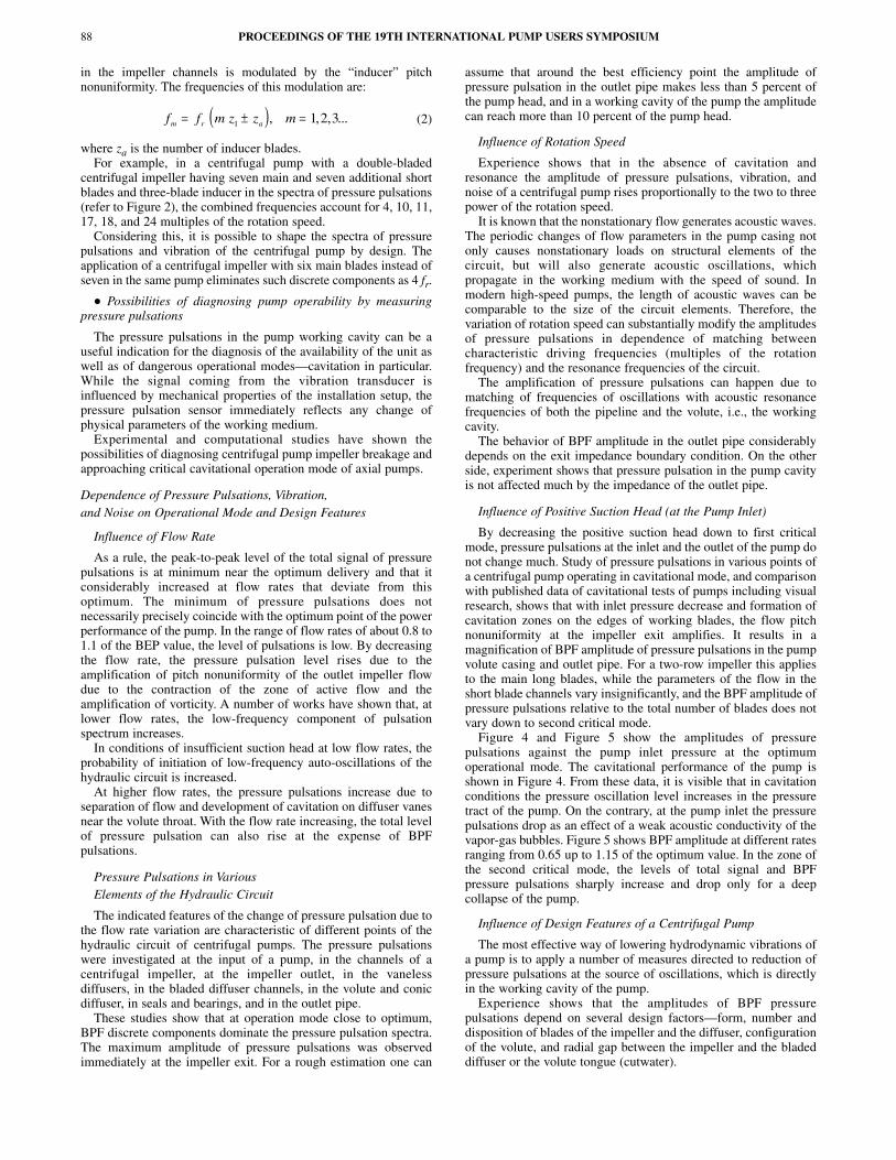
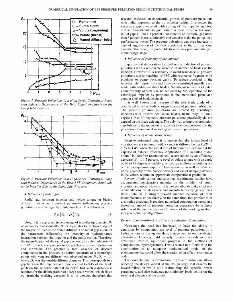
Figure 4 and Figure 5 show the amplitudes of pressurepulsations against the pump inlet pressure at the optimumoperational mode. The cavitational performance of the pump isshown in Figure 4. From these data, it is visible that in cavitationconditions the pressure oscillation level increases in the pressuretract of the pump. On the contrary, at the pump inlet the pressurepulsations drop as an effect of a weak acoustic conductivity of thevapor-gas bubbles. Figure 5 shows BPF amplitude at different ratesranging from 0.65 up to 1.15 of the optimum value. In the zone ofthe second critical mode, the levels of total signal and BPFpressure pulsations sharply increase and drop only for a deepcollapse of the pump.
Influence of Design Features of a Centrifugal Pump
The most effective way of lowering hydrodynamic vibrations ofa pump is to apply a number of measures directed to reduction ofpressure pulsations at the source of oscillations, which is directlyin the working cavity of the pump.
Experience shows that the amplitudes of BPF pressurepulsations depend on several design factors—form, number anddisposition of blades of the impeller and the diffuser, configurationof the volute, and radial gap between the impeller and the bladeddiffuser or the volute tongue (cutwater).
PROCEEDINGS OF THE 19TH INTERNATIONAL PUMP USERS SYMPOSIUM88
( )f f m z z mm r a= ± =1 1 2 3, , , ...
NUMERICAL SIMULATION OF BPF PRESSURE PULSATION FIELD IN CENTRIFUGAL PUMPS 89
Figure 4. Pressure Pulsations in a High-Speed Centrifugal Pumpwith Inducer: Dependence of the Total Signal Amplitude on thePump Inlet Pressure.
Figure 5. Pressure Pulsations in a High-Speed Centrifugal Pumpwith Inducer: Dependence of the Base BPF Component Amplitudeat the Impeller Exit on the Pump Inlet Pressure.
• Influence of radial gap
Radial gap between impeller and volute tongue or bladeddiffuser inlet is an important parameter influencing pressurepulsation in a centrifugal hydraulic machine. It is defined as:
(3)
Usually it is expressed in percentage of impeller tip diameter D2or radius R2. Consequently, D3 or R3 relates to the lower edge ofthe tongue or inlet of the vaned diffuser. The radial gap is one ofthe parameters influencing the intensity of hydrodynamicinteraction between the impeller and the pump casing. Therefore,the magnification of the radial gap ensures, as a rule, reduction ofall BPF discrete components in the spectra of pressure pulsationsand vibration. The practically total absence of discretecomponents in the pressure pulsation spectrum of a centrifugalpump with vaneless diffuser was observed under D4/D2 = 1.4,where D4 was the outside diffuser diameter. This corresponds to agap between the impeller and tongue equal to 0.45 of the bladepitch on the impeller external diameter. Just such a distance isrequired for the disintegration of a large-scale vortex, which flowsout from the working cascade. It is no wonder, therefore, that
research indicates an exponential growth of pressure pulsationswith radial approach to the tip impeller radius. In practice, thenecessary gap is ensured with cutting of the impeller and (or)diffuser vanes/volute tongue, which is most effective for smallinitial gaps (1.0 to 1.5 percent). An increase of the radial gap morethan 5 percent is not so effective and can also make the pump headperformance worse. The pressure pulsations can even increase incase of aggravation of the flow conditions in the diffuser vanecascade. Therefore, it is preferable to select an optimum radial gapat the design stage.
• Influence of geometry of the impeller
Experimental studies show the tendency of reduction of pressurepulsations with a reasonable increase in number of blades of theimpeller. However, it is necessary to avoid resonance of pressurepulsations due to matching of BPF with resonance frequencies ofpipelines or pump working cavity. To reduce overload in theimpeller inlet region, two and three row centrifugal impellers aremade with additional short blades. Significant reduction of pitchnonuniformity of flow can be achieved by the separation of thecentrifugal impeller by partitions in the meridional plane andangular shift of blade channels.
It is well known that increase of the exit blade angle of acentrifugal impeller leads to magnification of pressure pulsations.The greatest pressure pulsations are created by centrifugalimpellers with forward bent radial blades. In the range of smallangles (10 to 30 degrees), pressure pulsations practically do notdepend on the blade exit angle. The only way to improve predictioncapabilities is the inclusion of impeller flow computation into theprocedure of numerical modeling of pressure pulsations.
• Influence of pump casing design
From experimental data it is known that the lowest level ofvibration occurs in pumps with a vaneless diffuser having D4/D2 =1.35 to 1.45, where the radial size of the pump is increased at theexpense of reduced efficiency. Application of a so-called “sidedvolute” is therefore recommended, accompanied by an efficiencydecrease of 1 to 1.5 percent. A bevel of volute tongue with an angleof 30 to 45 degrees is widely practiced, as it allows smoothing outof the blade-passing impulse. These measures, as well as influenceof the geometry of the bladed diffuser and use of damping devicesin the volute, require an appropriate computational prediction.
Review of publications indicates that experimental studies haveaccumulated considerable material on the problem of pumpvibration and noise. However, it is not possible to make strict rec-ommendations for designers and manufacturers by generalizingthese data in a straightforward manner because of theirincompleteness or peculiarity. At the same time, this problem is ofa complex character. It requires numerical computation based on atheoretical model of pressure pulsation generation by a directsolution of the main equations of motion of the working mediumin a given pump configuration.
Review of State-of-the-Art of Pressure Pulsation Computation
Nowadays the need has increased to have the ability todetermine by computation the level of pressure pulsations in ahydraulic circuit during the design stage and to outline designalternatives. However, until recently, reliable methods were notdeveloped despite significant progress in the methods ofcomputational hydrodynamics. This is related to difficulties in theconstruction of an adequate mathematical model of thephenomenon that could allow the creation of an effective computercode.
The computational determination of pressure pulsations allowsselecting the design variant at the design stage that ensures thelowest vibration while still maintaining the specific powerparameters, and also evaluates nonstationary loads acting on thestructural elements of the circuit.
( )δ = −D D D3 2 2/

Computational Model of Joffe-Panchenko
This model is the first attempt to treat the problem of hydraulicvibration in centrifugal pumps with a vaned diffuser. Oneimportant problem of pump design is the choice of the optimumnumber of impeller blades z1 and of a vaned diffuser z2. For acertain unfavorable ratio z1/z2, the amplification of BPF oscil-lations or its harmonics can occur. In the Joffe-Panchenko (1972)model, dynamic forces acting on diffuser vanes cause BPFvibration. Such forces can be represented as a Fourier series.
Factors of such a series depend on the assumed function of forcevariation with time (density of the working fluid, profile of flowvelocities, geometric parameters of the blade cascade, gap betweenthe impeller and diffuser, etc.).
The optimum ratio of numbers of blades is selected so that thedynamic force and moment obtained by summation over alldiffuser vanes are at a minimum. The fulfillment of the twoinequalities for the first three to four harmonics requires that:
(4)
where:k = Harmonic orderJ = Positive integer
This model is correct when a pump case vibrates as a rigid body.Besides, an important factor like pressure pulsations in the pumpworking cavity is not taken into account here.
The main conclusion derived from this theory is that the sourceof pulsations in a centrifugal pump has a determined spatialstructure.
Computational Model of Chen
For the first time a computational model for the determination ofBPF pressure pulsations in the volute casing of a centrifugal pumpwith a vane diffuser was created by Chen (1961). Thecomputational model of Chen imitates the volute casing with avaned diffuser: vaned channels of the diffuser and of the volute aresubstituted by tubes of constant cross section. The boundaryconditions at the vane channel inlet of the diffuser are given asacoustic perturbations of pressure and velocity.
At the diffuser channel exit the condition of flow continuity isimposed. At the beginning of volute and in the throttle, cut T andO in Figure 6, the boundary conditions are determined by theappropriate reflection coefficients.
Figure 6. Computational Model of Chen.
In this work, the linearized one-dimensional wave equation ofoscillations in the volute is presented. The solution is noted interms of direct and reflected waves propagating toward the throttlesection and in the opposite direction, respectively. The formulaefor the determination of amplitudes of pressure pulsations havebeen obtained. However, for the realization of calculations usingthese formulae, it is necessary to know the magnitude of velocityoscillations at the exit of the vane channel of the diffuser.Determination of velocity pulsations is a complicated hydro-dynamic problem, which in the quoted work has not been solved.Consequently, no quantitative result was obtained.
On a qualitative level such an approach allows identification ofan approximate criterion of resonance of pressure pulsations in thevolute as the interference of acoustic waves originating in differentchannels of a diffuser is implied in the model. However, a similarresult can be obtained in a simpler way only from the analysis ofphase relations for pressure impulses.
So-called “backward wave resonance” in the initial cross sectionof the volute occurs when:
(5)
“Direct wave resonance” will take place according to Chen (1961)when:
(6)
where:fr = Frequency of rotation, HzDm = Average diameter of the voluteUm = Average flow velocity of the fluid within the volutea = Average speed of soundk = Harmonic numberJ = ...�3, �2, �1, 0, +1, +2, +3
Any further development of this method would not provide thepossibility of accounting for influence of pump geometry onabsolute values of pressure pulsations. This theory gives anexample of pure acoustical method of solution of the problem ofdetermination of pressure pulsation.
Computational Model of Sukup and Other Semiempirical Models
As already mentioned above, for the determination ofamplitudes of pressure BPF oscillations in a pump casing, it isnecessary to know the distribution of flow parameters in therelative motion on the pitch of the impeller exit radius.
With the approximation of potential two-dimensional flow of anideal fluid, such a problem was addressed by Sukup (1974, 1975).It was proposed that at the exit of each impeller channel, the flowconsisted of an active zone and a zone of return flow. Thus due topassing of working blades relative to diffuser channels, at the inletof the latter there are pulsations of delivery, which can result invelocity and pressure fluctuations.
This method has two serious defects. First, the application of thepotential flow theory gives in essence an incorrect picture ofrelative velocity distribution across the pitch of the workingcascade. Second, a rough simplification of the mathematical modelof generation of pressure pulsations is made: the amplitude ofpressure pulsation is directly proportional to the amplitude ofvelocity pulsations in the absolute motion at the diffuser input.Nevertheless, this theory brings the idea of unsteady boundarycondition as a rotating velocity profile at the impeller exit.
Various semiempirical laws can certainly render a great favor inan engineer’s work. Such laws may link relative amplitude ofpressure pulsations at the output (exit) of the centrifugal pump tothe operation mode and design factors. However, they can haveonly limited application for similar pumps. Besides, they do notgive any information about the level of pressure pulsationsimmediately in the pump working cavity and do not take intoaccount the possibility of emergence of acoustic resonance in thehydraulic circuit.
“Direct Solution” Method
Some works were published in which the methods of predictionof pressure pulsations were developed by a direct computation ofnonstationary two-dimensional flow in a centrifugal impeller andvolute with solution of averaged Navier-Stokes equations and k-ε
PROCEEDINGS OF THE 19TH INTERNATIONAL PUMP USERS SYMPOSIUM90
kz
zJ
kz
zJ1
2
1
2
1± ≠ ≠;
z z
z
f D
a U
z
z z
J
kr m
m
2 1
2
1
2 1
1− −
−⋅
−
= +π
z z
z
f D
a U
z
z z
J
kr m
m
2 1
2
1
2 1
1−
+−
⋅−
= −
π
NUMERICAL SIMULATION OF BPF PRESSURE PULSATION FIELD IN CENTRIFUGAL PUMPS 91
models of turbulence. Other approaches used solutions ofhydrodynamic equations accompanied by laser anemometricmeasurements.
Computation of pressure pulsation by resolving the equations ofhydrodynamics as developed by Croba and Kueny (1992) andCroba, et al. (1993), offer a method of computation ofnonstationary two-dimensional flow in a centrifugal impeller andvolute with solution of average Navier-Stokes equations and k-εmodels of turbulence. The computation is carried out by a directmethod on two different grids—for the impeller and the volute.The transfer of parameters from one area into the other is carriedout with the help of a bilinear interpolation in the zone ofoverlapping of finite difference grids (so-called “sliding grids”). Inthis method, the essential difficulty in defining the pressure-boundary-condition at the volute (pump) outlet is not overcome.Namely, this is assumed to be constant, though it is obvious that thedownstream pressure oscillates at the blade-passing frequency.There is no possibility of computing correct amplitude of pressurepulsations in the outlet part of the volute and in the conical diffuserof the centrifugal pump. Simply it is the result of application of themodel of incompressible liquid.
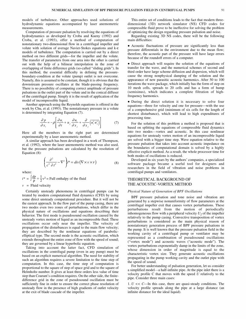
Another approach using the Reynolds equations is offered in thework by Chu, et al. (1993). The nonstationary pressure in a voluteis determined by integrating Equation (7).
(7)
Here all the members in the right part are determinedexperimentally by a laser anemometric method.
A similar approach has been developed in a work of Thompson,et al. (1992), where the laser anemometric method was also used,but the pressure pulsations are calculated by the resolution ofEquation (8):
(8)
where:
i* = ∫ � v2 = Full enthalpy of the fluid
v = Fluid velocity
Certainly unsteady phenomena in centrifugal pumps can betreated by modern computational fluid dynamics (CFD) by usingsome direct unsteady computational procedure. But it will not bethe easiest approach. In the flow part of the pump casing, there aretwo modes even two zones of perturbations, which differ in thephysical nature of oscillations and equations describing theirbehavior. The first mode is pseudosound oscillation caused by theunsteady vortex motion of liquid as an incompressible fluid. Theseoscillations occur only near the impeller. The velocity ofpropagation of the disturbances is equal to the main flow velocity;they are described by the nonlinear equations of parabolic-elliptical type. The second mode is the acoustic oscillation, whichextends throughout the entire zone of flow with the speed of sound;they are governed by a linear hyperbolic equation.
Taking into account the latter fact, CFD simulation ofoscillations in the centrifugal pump (even in any pump) must bebased on an explicit numerical algorithm. The need for stability ofsuch an algorithm requires a severe limitation to the time step ofcomputation. In this case, the time step of computation isproportional to the square of step of space grid and to the square ofHelmholtz number. It gives at least three orders less value of timestep than Courant’s condition requires. On the other side, the finite-difference grid in the zone of pseudosound oscillation must besufficiently fine in order to ensure the correct phase resolution ofunsteady flow in the presence of high gradients of outlet velocityat the exit of blade cascade of the impeller.
This entire set of conditions leads to the fact that modern three-dimensional (3D) network simulator (NS) CFD codes forcompressible fluid prove to be ineffective for solving the problemof optimizing the design regarding pressure pulsation and noise.
Regarding existing 3D NS codes, there will be the followingmain difficulties:
• Acoustic fluctuations of pressure are significantly less thanpressure differentials in the environment due to the mean flow;therefore, the acoustic part of the pressure will have large errorsbecause of the roundoff errors of a computer.
• Direct approach will require the solution of the equations oftransfer for the wave, and the numerical schemes of second andthird order have large scheme diffusion and dispersion, which willcause the strong nonphysical damping of the solution and theappearance of new parasitic acoustic harmonics. After 50 to 100iterations the wave package, which initially has the form of step on10 mesh cells, spreads to 20 cells and has a form of hump(semisinus), which indicates a complete filtration of high-frequency harmonics.
• During the direct solution it is necessary to solve fourequations—three for velocity and one for pressure—with the useof a comprehensive grid (minimum of six cells for the length ofshortest disturbance), which will lead to high expenditures ofprocessing time.
For the solution of this problem a method is proposed that isbased on splitting the equations of compressible fluid dynamicsinto two modes—vortex and acoustic. In this case nonlinearequations for unsteady vortex motion of an incompressible liquidare solved with a bigger time step. Wave equation relative to thepressure pulsation that takes into account acoustic impedance onthe boundaries of computational domain is solved by a highlyeffective explicit method. As a result, the whole processor time forboth modes of oscillations is reduced.
Developed in six years by the authors’ companies, a specializedsoftware package became a useful tool for designers andresearchers in the field of vibration and noise problems incentrifugal pumps and ventilators.
THEORETICAL BACKGROUND OFTHE ACOUSTIC-VORTEX METHOD
Physical Nature of Generation of BPF Oscillations
BPF pressure pulsation and tone noise and vibration aregenerated by a stepwise nonuniformity of flow parameters at thecentrifugal impeller exit that causes vortex perturbations. Theseperturbations result from the motion of periodicallyinhomogeneous flow with a peripheral velocity U2 of the impellerrelatively to the pump casing. Convective transposition of vortexperturbations is considered as the main physical reason ofnonstationary generation process of BPF pressure pulsations inthe pump. It is well known that the pressure pulsation field in theworking cavity of a centrifugal pump or ventilator may berepresented as a combination of pseudosound oscillations(“vortex mode”) and acoustic waves (“acoustic mode”). Thevortex perturbations exponentially damp in the limits of the zone,whose dimension in order of magnitude is equal to thecharacteristic vortex size. They generate acoustic oscillationspropagating in the pump working cavity and the outlet pipe withthe speed of sound.
For better understanding of pulsation generation, let us considera simplified model—a half-infinite pipe. At the pipe inlet there is avelocity profile C that moves with the speed U relatively to thepipe. Consider three main cases:
1. U << C—In this case, there are quasi-steady conditions. Thevelocity profile spreads along the pipe at a large distance (aninfinite distance for the ideal liquid).
( )∂∂
ρ ∂∂
∂∂
∂∂
p
x
u
tu
u
x xu u
i
ij
i
j j
i j= − + + ′ ′
( )∂∂
ν2
2 2
2
c ti div v− ∇
= ∇ × ×*
12
dpρ
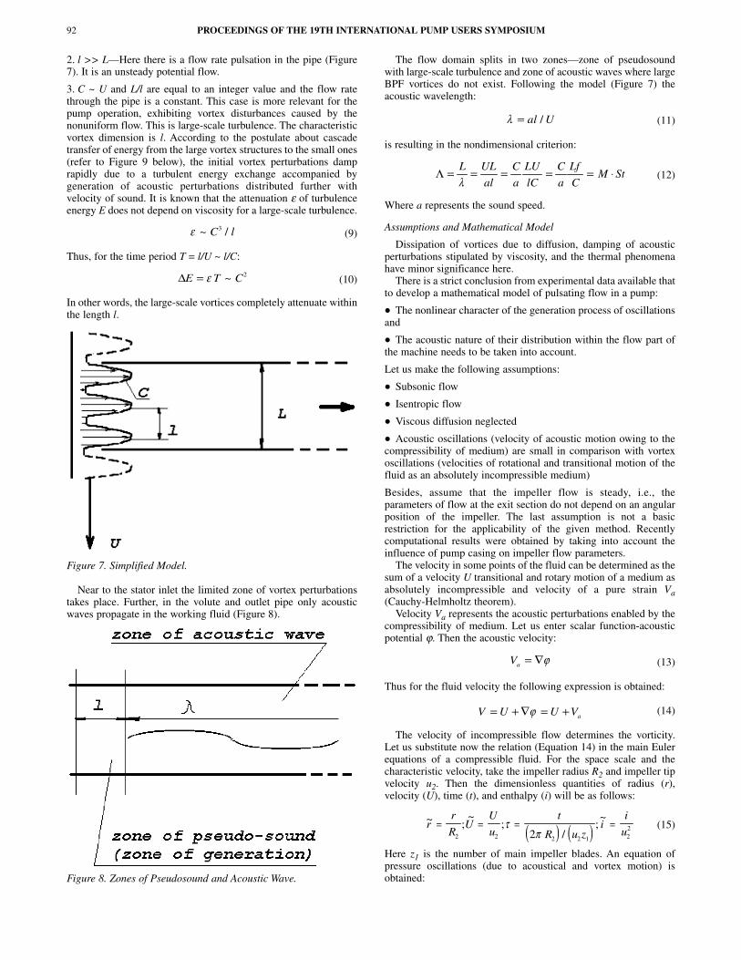
2. l >> L—Here there is a flow rate pulsation in the pipe (Figure7). It is an unsteady potential flow.
3. C ~ U and L/l are equal to an integer value and the flow ratethrough the pipe is a constant. This case is more relevant for thepump operation, exhibiting vortex disturbances caused by thenonuniform flow. This is large-scale turbulence. The characteristicvortex dimension is l. According to the postulate about cascadetransfer of energy from the large vortex structures to the small ones(refer to Figure 9 below), the initial vortex perturbations damprapidly due to a turbulent energy exchange accompanied bygeneration of acoustic perturbations distributed further withvelocity of sound. It is known that the attenuation ε of turbulenceenergy E does not depend on viscosity for a large-scale turbulence.
(9)
Thus, for the time period T = l/U ~ l/C:
(10)
In other words, the large-scale vortices completely attenuate withinthe length l.
Figure 7. Simplified Model.
Near to the stator inlet the limited zone of vortex perturbationstakes place. Further, in the volute and outlet pipe only acousticwaves propagate in the working fluid (Figure 8).
Figure 8. Zones of Pseudosound and Acoustic Wave.
The flow domain splits in two zones—zone of pseudosoundwith large-scale turbulence and zone of acoustic waves where largeBPF vortices do not exist. Following the model (Figure 7) theacoustic wavelength:
(11)
is resulting in the nondimensional criterion:
(12)
Where a represents the sound speed.
Assumptions and Mathematical Model
Dissipation of vortices due to diffusion, damping of acousticperturbations stipulated by viscosity, and the thermal phenomenahave minor significance here.
There is a strict conclusion from experimental data available thatto develop a mathematical model of pulsating flow in a pump:
• The nonlinear character of the generation process of oscillationsand
• The acoustic nature of their distribution within the flow part ofthe machine needs to be taken into account.
Let us make the following assumptions:
• Subsonic flow
• Isentropic flow
• Viscous diffusion neglected
• Acoustic oscillations (velocity of acoustic motion owing to thecompressibility of medium) are small in comparison with vortexoscillations (velocities of rotational and transitional motion of thefluid as an absolutely incompressible medium)
Besides, assume that the impeller flow is steady, i.e., theparameters of flow at the exit section do not depend on an angularposition of the impeller. The last assumption is not a basicrestriction for the applicability of the given method. Recentlycomputational results were obtained by taking into account theinfluence of pump casing on impeller flow parameters.
The velocity in some points of the fluid can be determined as thesum of a velocity U transitional and rotary motion of a medium asabsolutely incompressible and velocity of a pure strain Va(Cauchy-Helmholtz theorem).
Velocity Va represents the acoustic perturbations enabled by thecompressibility of medium. Let us enter scalar function-acousticpotential ϕ. Then the acoustic velocity:
(13)
Thus for the fluid velocity the following expression is obtained:
(14)
The velocity of incompressible flow determines the vorticity.Let us substitute now the relation (Equation 14) in the main Eulerequations of a compressible fluid. For the space scale and thecharacteristic velocity, take the impeller radius R2 and impeller tipvelocity u2. Then the dimensionless quantities of radius (r),velocity (U), time (t), and enthalpy (i) will be as follows:
(15)
Here z1 is the number of main impeller blades. An equation ofpressure oscillations (due to acoustical and vortex motion) isobtained:
PROCEEDINGS OF THE 19TH INTERNATIONAL PUMP USERS SYMPOSIUM92
ε ~ /C l3
∆E T C= ε ~ 2
λ = al U/
Λ = = = = = ⋅L UL
al
C
a
LU
lC
C
a
Lf
CM St
λ
Va = ∇ϕ
V U U Va= + ∇ = +ϕ
( ) ( )~ ;
~;
/;~
rr
RU
U
u
t
R u zi
i
u= = = =
2 2 2 2 1 22
2τ
π

NUMERICAL SIMULATION OF BPF PRESSURE PULSATION FIELD IN CENTRIFUGAL PUMPS 93
(16)
Parameter Λ is the dimensionless similarity criterion of the givenproblem. A detailed derivation of Equation (16) is outlined inAPPENDIX A.
It is simple to show that the parameter Λ is the product of theMach number and the Strouhal number and represents the ratio ofthe impeller tip radius R2 to the main BPF wavelength λ. Itcorresponds to the Ho (Helmholtz) number in classical acoustics.
(17)
where:fb1 = Main blade-passing frequencya = Speed of sound
The amplitude of pressure pulsation in a hydraulic machine is byan order of magnitude lower than the mean undisturbed pressure.Thus for enthalpy oscillations (as a sum of vortex and acousticperturbations) it is possible to write approximately:
(18)
where:P = Pressure of compressible fluidP0 and ρ0 = Mean pressure and density
Similarly for oscillations of the function g, pressure pulsation(Pv � P0) is obtained in “vortex-mode motion”:
(19)
Solution of Equation 16 is divided into two parts—computationof the incompressible flow for the determination of the disturbingfunction, and solution of the inhomogeneous wave equation for thedetermination of h.
The problem of pressure oscillation field determination splitsinto three main steps. The first one is the incompressible liquidflow analysis in the impeller to obtain unsteady boundarycondition of the vortex mode flow. This boundary condition can berepresented in the form of rotating velocity distribution “attached”to the impeller exit diameter. The second step is the unsteadyvortex mode flow computation in the working cavity of pump orventilator with consequential determination of the disturbance(right-part) function, and the third one is solution of the waveequation relative to pressure oscillations. The computationalprocedure is built on two-dimensional (2D) numerical methods. Inthat case, a uniform radial velocity distribution along the impelleror (equivalent) volute width is applied.
By introducing the polar coordinate system Θ - R at the pumpaxis and using the vorticity and streamline functions by means ofthe relations:
(20)
and
(21)
The following equations are obtained:
(22)
Boundary Conditions
Impeller Flow Analysis
Impeller flow is treated by the discrete vortex method (DVM).The DVM is used for impeller flow computation. Following recentachievements in the theory of vortex turbulent flow, DVM gives asimple and clear way of modeling large-scale or coherentstructures. The important fact established is that the behavior of thelarge-scale turbulence does not depend on the viscosity of liquid.Large-scale characteristics of the flow can be described by Eulerequations. The DVM thus becomes a very effective method foranalyzing the zone of large-scale turbulence that is the cause ofBPF pulsation (Figure 9).
Figure 9. Cascade Pass of Turbulent Energy.
The DVM is a genuine unsteady method and it has a potentialfor the full simulation of turbulence, including stochasticphenomena and viscous diffusion in 3D space. The DVM gives acomplete mathematical description of turbulence withoutadditional assumptions such as k-ε model, etc., in 3D NS codes.
The software package has modular structure so that it is possibleto use a third-party code for impeller flow computation. DVM isdescribed in APPENDIX A.
Having the pump geometry defined, the first step in the impellerflow analysis gives an unsteady boundary condition for thesolution of vortex mode equations in the form of (Ψ, ζ) equations.
Vortex Mode Flow
At the second step, the unsteady direct procedure provides aconverging oscillatory solution for the incompressible liquid flow(so called “pseudosound” oscillations). In this step the followingboundary conditions apply:
• On the pump volute wall:
(23)
Λ = = = = ⋅ =u z
a
f R
a
u
a
f R
uM St
Rb b2 1 1 2 2 1 2
2
2
2π λ
( )h
P P
u
P
u≈
−=
′0
0 22
0 22ρ ρ
( )g
P P
u
P
uv v≈
−= ′0
0 22
0 22ρ ρ
Θ = = =γη γγε γε, / ,R R e E e2
Uu U
EU
u UE
EU
U U
R
2 2
1 1
1
= = = = −
= + −
ξ η
ηη ξ
∂∂ η
∂∂ ξ
ς γ∂∂ ξ
∂∂ η
Ψ ΨΘ, ,
( ) ( )
Λ
Ψ Ψ
22
2 2
2
2
2
2
2
2
2
2
2
1
1
2
∂∂ τ
∂∂ η
∂∂ ξ
∂∂ η
∂∂ ξ
ζ
∂ ζ∂ τ
π ∂∂ η
ζ ∂∂ ξ
ζη ξ
h
E
h hs
E
z EU U
− +
=
+ = −
= − +
,
.
Ψw wconst= =, ,ζ 0
Λ ∆ ∆22
2
∂∂ τ
hh g− = −
~ ~

• At the volute inlet boundary:
(24)
• At the pump casing exit:
(25)
Impedance Condition for the Wave Equation
By using a local specific acoustic impedance Z (complex value),the boundary condition at the impeller outlet and pump casing exitsection can be put in the form:
(26)
where:k = Number of BPF harmonicn = Normal direction to the boundary
Volute casing walls are assumed rigid. Nevertheless, there is apossibility of defining a local specific impedance of the pumphousing wall that will be interesting to study the effect of dampingcoating.
Solution Method
The problem of pressure oscillation field determination splitsinto three main tasks. The first one is the incompressible liquidflow analysis in the impeller to obtain unsteady boundarycondition of the vortex mode flow. The second one is the unsteadyvortex mode flow computation into the working cavity of the pumpwith consequential determination of the disturbance function, andthe third is the solution of wave equation relative to pressureoscillations, satisfying the complex specific impedance foracoustic mode and unsteady boundary condition for thepseudosound oscillations.
Application Domain
The code is applicable to centrifugal pumps or ventilators withspecific speed ns < 150 (ns = 193.3 ω QH�3/4, SI units are applied,ns < 2120 using rpm, US gpm, ft) under the normal operationmode. Normal operation mode guarantees the accuracy ofcomputation within 1 to 3 dB, based on the following conditions:
• Subsonic flow
• Homogeneous fluid
• No cavitation, operation is before the first critical mode
• Delivery range is 0.8 to 1.3 of the BEP value
Geometry may include arbitrary impeller blade profiles andarbitrary volute-diffuser geometry with one outlet pipe.
A built-in interface for the determination of impedanceboundary conditions gives a possibility of taking into account theconnected circuit.
Software Package and Computation Process
Numerical algorithms are realized in three main modules writtenin C and C��. Interface code permits an easy input of data suchas impeller and casing geometry, operation mode, parameters ofworking fluid, acoustic impedance, and parameters controlling thecomputation process. It provides an environment to work with3 � 3 different cases simultaneously. Once the computationprocedure, which goes consequently through three main steps,finishes, it becomes possible to obtain the fluctuating pressure mapin the casing at a selected time point as well as the pressure timehistory at any point within the working cavity with thecorresponding root-mean-square (RMS) value and spectrum data.
EXAMPLES OF COMPUTATIONAND EXPERIMENTAL VALIDATION
Experience shows that amplitudes of BPF pressure pulsationdepend on several design factors—shape, number, and dispositionof blades of the impeller and diffuser vanes, configuration of thevolute, radial gap between the impeller, and volute tongue orbladed diffuser.
Due to the presence of two modes of pressure oscillation, thepump geometrical parameters can affect pressure pulsation in thepseudosound zone and in the zone of acoustic oscillations. Forexample, a change of radial gap influences vortex (pseudosound)fluctuations and acoustic pulsations as the radial gap is located inthe zone of pseudosound, i.e., in the source of acoustic waves.
Amplification of pressure pulsation can happen due to matchingof frequencies of oscillations with acoustic resonance frequenciesof both the outlet duct and the pump casing flow cavity. Thespecific resonance phenomena often take place due to interactionbetween acoustic waves emitted from different vane channels withdifferent phases defined by relation of impeller blades and diffuservanes. Therefore, the variation of rotational speed, number ofimpeller blades, and diffuser vanes can substantially modify theamplitudes of pressure pulsation due to the resonance in the pumpcavity. All these topics can be the subject of a computational studywith the numerical method developed. Possible tasks that can besolved with the method are outlined below.
• Pressure pulsations in various points of a pump volute casingand diffuser
• Influence of flow rate
• Influence of rotation speed
• Influence of radial gap
• Influence of geometry of the impeller (number and shape ofblades, intermediary short blades, arbitrary number of blade rows)
• Influence of a pump casing geometry
• Effect of damping coating
• Effect of the outlet duct impedance
• Influence of geometry of the bladed diffuser
• Determination of unsteady loads acting on impeller and diffuserblades
• Determination of diagnostics’ signs such as breakage of impellerblade
In Table 1, one can see a few computational estimations of theinfluence of various factors on pressure pulsation amplitude.
Table 1. Various Factors Influencing Pressure Pulsation.
Validation Using Experimental Centrifugal Pump
A centrifugal experimental air pump (Tourret, et al., 1991) wasused for validation of the numerical method. The experimental pumpwas tested with rotation speed of 1400 rpm and flow rate 0.0139 m3/s(0.0456 ft3/s). There are more than 300 measurement points ofpressure pulsation located in the volute and at the pump exit.
In the computational procedure, the unsteady boundarycondition was obtained as a stationary velocity profile at theimpeller exit that rotates with the impeller. This case corresponds
PROCEEDINGS OF THE 19TH INTERNATIONAL PUMP USERS SYMPOSIUM94
Factor Rough estimation of influence (dB)
Position in the pump working cavity 15
Radial gap change from 4% to 7% (no resonance case) 6 Increasing rotation speed by 20% (no resonance case) 3 Specific impeller geometry change (no resonance case) 9 Relation of numbers of impeller and diffuser blades (resonance)
20
Damping coating in the conical diffuser 8 Outlet pipe acoustic impedance (resonance) 15
Ψ = ∫γ ηξU d ,
∂∂
∂ ζ∂
Ψn n
= =0 0, .
( ) ( )∂∂
∂∂ τ
h g
n
k
Z
h gk k
k
k k−= −
−Λ

NUMERICAL SIMULATION OF BPF PRESSURE PULSATION FIELD IN CENTRIFUGAL PUMPS 95
to symmetrical impeller flow when the impeller is consideredwithout volute and discharging into an infinite medium.Distribution of relative velocity (reduced by impeller tip velocity)in impeller channels (Figure 10) shows low-velocity zones near thesuction side of each blade.
Figure 10. Relative Velocity in Impeller Channels.
This leads to the nonuniform distribution of flow parameters atthe impeller exit that are presented in Figure 11 and Figure 12. Inthese figures, the pressure side of the blade channel is on the left,while the impeller rotation goes to the right. Thus, the maximumof radial velocity and minimum of absolute tangential velocity arelocated near the pressure side of the blade.
Figure 11. Absolute Radial Velocity along the Impeller ChannelSpan at the Impeller Exit.
With more than 10,000 overall mesh nodes (number of meshnodes in impeller channel span is 12), total computation time on aPentium® II processor is six hours. Seven BPF harmonics areincluded for the computation of pressure pulsation. The pump hasno exit pipe, thus a computation open-end-condition is taken forthe acoustic mode.
The characteristic feature of unsteady pressure in the pumpvolute is the presence of lower pressure zones linked with bladeexit edges and rotating with the impeller. Computation also showssuch zones (Figure 13). For comparison, Figure 14 presents theexperimental oscillatory part of the static pressure field.
Figure 12. Absolute Tangential Velocity along the ImpellerChannel Span at the Impeller Exit.
Figure 13. Unsteady Pressure Map in the Volute (Computation forSeven Harmonics of BPF); Grayscale Palette from �14Pa to�14Pa.
Figure 14. Unsteady Pressure Map (Experiment, Lower Flow Rate).
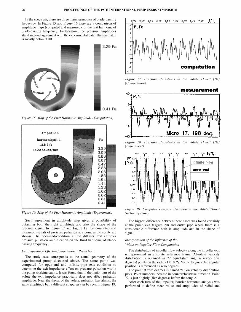
In the spectrum, there are three main harmonics of blade-passingfrequency. In Figure 15 and Figure 16 there are a comparison ofamplitude maps (computed and measured) for the first harmonic ofblade-passing frequency. Furthermore, the pressure amplitudesstand in good agreement with the experimental data. The mismatchis mostly below 3 dB.
Figure 15. Map of the First Harmonic Amplitude (Computation).
Figure 16. Map of the First Harmonic Amplitude (Experiment).
Such agreement in amplitude map gives a possibility ofobtaining both the right amplitude and also the shape of thepressure signal. In Figure 17 and Figure 18, the computed andmeasured signals of pressure pulsation at a point in the volute areshown. The open-end-condition at the diffuser exit enforcespressure pulsation amplification on the third harmonic of blade-passing frequency.
Exit Impedance Effect—Computational Prediction
The study case corresponds to the actual geometry of theexperimental pump discussed above. The same pump wascomputed for open-end and infinite-pipe exit condition todetermine the exit impedance effect on pressure pulsation withinthe pump working cavity. It was found that in the major part of thevolute the exit impedance practically does not affect pulsationamplitude. Near the throat of the volute, pulsation has almost thesame amplitude but a different shape, as can be seen in Figure 19.
Figure 17. Pressure Pulsations in the Volute Throat [Pa](Computation).
Figure 18. Pressure Pulsations in the Volute Throat [Pa](Experiment).
Figure 19. Computed Pressure Pulsation in the Volute ThroatSection of Pump.
The biggest difference between these cases was found certainlyat the pump exit (Figure 20) and outlet pipe where there is aconsiderable difference both in amplitude and in the shape ofsignal.
Incorporation of the Influence of theVolute on Impeller Flow Computation
The distribution of impeller flow velocity along the impeller exitis represented in absolute reference frame. Absolute velocitydistribution is obtained in 72 equidistant angular (every fivedegrees) points on the radius 1.018 R2. Volute tongue edge angularposition is referenced as zero degrees.
The point at zero degrees is named “1” on velocity distributionplots. Point numbers increase in counterclockwise direction. Point72 is just slightly (five degrees) before the tongue.
After each turn of the impeller, Fourier harmonic analysis wasperformed to define mean value and amplitudes of radial and
PROCEEDINGS OF THE 19TH INTERNATIONAL PUMP USERS SYMPOSIUM96
NUMERICAL SIMULATION OF BPF PRESSURE PULSATION FIELD IN CENTRIFUGAL PUMPS 97
Figure 20. Computed Pressure Pulsation at the Pump Exit.
tangential components of absolute velocity. Blade passage periodwas taken as the main period of Fourier analysis.
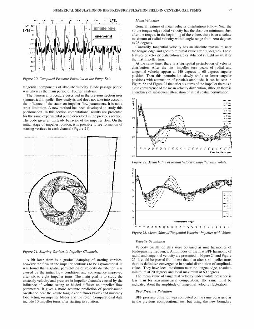
The numerical procedure described in the previous section usessymmetrical impeller flow analysis and does not take into accountthe influence of the stator on impeller flow parameters. It is not astrict limitation. A new method has been developed to study thisphenomenon. In this section computational results are presentedfor the same experimental pump described in the previous section.The code gives an unsteady behavior of the impeller flow. On theinitial stage of impeller rotation, it is possible to see formation ofstarting vortices in each channel (Figure 21).
Figure 21. Starting Vortices in Impeller Channels.
A bit later there is a gradual damping of starting vortices,however the flow in the impeller continues to be asymmetrical. Itwas found that a spatial perturbation of velocity distribution wascaused by the initial flow condition, and convergence improvedafter six to eight impeller turns. The main goal is to study theunsteady velocity and pressure in impeller channels caused by theinfluence of volute casing or bladed diffuser on impeller flowparameters. It gives a more accurate prediction of pseudosoundoscillation near the volute tongue (or diffuser blade) and unsteadyload acting on impeller blades and the rotor. Computational datainclude 10 impeller turns after starting its rotation.
Mean Velocities
General features of mean velocity distributions follow. Near thevolute tongue edge radial velocity has the absolute minimum. Justafter the tongue, in the beginning of the volute, there is an absolutemaximum of radial velocity within angle range from zero degreesto 25 degrees.
Contrarily, tangential velocity has an absolute maximum nearthe tongue edge and goes to minimal value after 30 degrees. Thesefeatures of velocity distribution are established straight away, afterthe first impeller turn.
At the same time, there is a big spatial perturbation of velocitydistribution. After the first impeller turn peaks of radial andtangential velocity appear at 140 degrees to 60 degrees angularposition. Then this perturbation slowly shifts to lower angularpositions with attenuation of (spatial) amplitude. It can be seen inFigure 22 and Figure 23 that after six turns of the impeller there is aclose convergence of the mean velocity distribution, although there isa tendency of subsequent attenuation of initial spatial perturbation.
Figure 22. Mean Value of Radial Velocity; Impeller with Volute.
Figure 23. Mean Value of Tangential Velocity; Impeller with Volute.
Velocity Oscillation
Velocity oscillation data were obtained as nine harmonics ofblade-passing frequency. Amplitudes of the first BPF harmonic ofradial and tangential velocity are presented in Figure 24 and Figure25. It could be proved from these data that after six impeller turnsthere is definitive convergence in spatial distribution of amplitudevalues. They have local maximum near the tongue edge, absoluteminimum at 20 degrees and local maximum at 60 degrees.
The mean value of tangential velocity under volute presence isless than for axisymmetrical computation. The same must beindicated about the amplitude of tangential velocity fluctuation.
BPF Pressure Pulsation
BPF pressure pulsation was computed on the same polar grid asin the previous computational test but using the new boundary
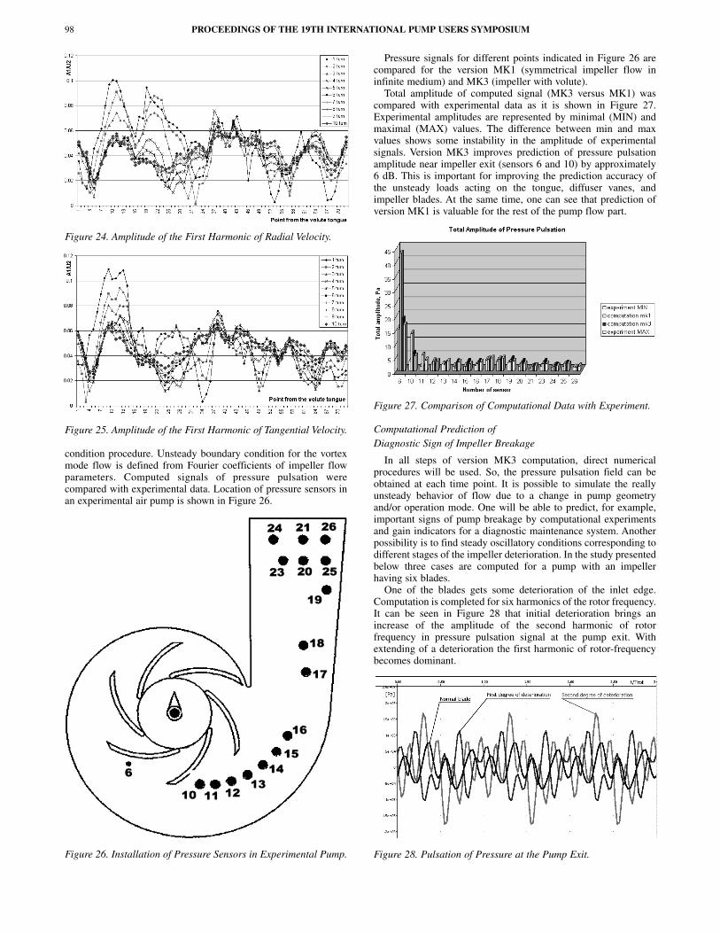
Figure 24. Amplitude of the First Harmonic of Radial Velocity.
Figure 25. Amplitude of the First Harmonic of Tangential Velocity.
condition procedure. Unsteady boundary condition for the vortexmode flow is defined from Fourier coefficients of impeller flowparameters. Computed signals of pressure pulsation werecompared with experimental data. Location of pressure sensors inan experimental air pump is shown in Figure 26.
Figure 26. Installation of Pressure Sensors in Experimental Pump.
Pressure signals for different points indicated in Figure 26 arecompared for the version MK1 (symmetrical impeller flow ininfinite medium) and MK3 (impeller with volute).
Total amplitude of computed signal (MK3 versus MK1) wascompared with experimental data as it is shown in Figure 27.Experimental amplitudes are represented by minimal (MIN) andmaximal (MAX) values. The difference between min and maxvalues shows some instability in the amplitude of experimentalsignals. Version MK3 improves prediction of pressure pulsationamplitude near impeller exit (sensors 6 and 10) by approximately6 dB. This is important for improving the prediction accuracy ofthe unsteady loads acting on the tongue, diffuser vanes, andimpeller blades. At the same time, one can see that prediction ofversion MK1 is valuable for the rest of the pump flow part.
Figure 27. Comparison of Computational Data with Experiment.
Computational Prediction of Diagnostic Sign of Impeller Breakage
In all steps of version MK3 computation, direct numericalprocedures will be used. So, the pressure pulsation field can beobtained at each time point. It is possible to simulate the reallyunsteady behavior of flow due to a change in pump geometryand/or operation mode. One will be able to predict, for example,important signs of pump breakage by computational experimentsand gain indicators for a diagnostic maintenance system. Anotherpossibility is to find steady oscillatory conditions corresponding todifferent stages of the impeller deterioration. In the study presentedbelow three cases are computed for a pump with an impellerhaving six blades.
One of the blades gets some deterioration of the inlet edge.Computation is completed for six harmonics of the rotor frequency.It can be seen in Figure 28 that initial deterioration brings anincrease of the amplitude of the second harmonic of rotorfrequency in pressure pulsation signal at the pump exit. Withextending of a deterioration the first harmonic of rotor-frequencybecomes dominant.
Figure 28. Pulsation of Pressure at the Pump Exit.
PROCEEDINGS OF THE 19TH INTERNATIONAL PUMP USERS SYMPOSIUM98
NUMERICAL SIMULATION OF BPF PRESSURE PULSATION FIELD IN CENTRIFUGAL PUMPS 99
Radial Gap Effect—Comparison with Experimental Data
Radial gap is expressed by Equation (3). Computational study ofradial gap effect was performed for an industrial-type centrifugalpump tested with measurements of pressure pulsation. The pumphas an impeller outlet radius of 173 mm (6.8 in) with five blades.The BEP operation mode case of 1200 rpm, Q = 0.066 m3/s(0.2165 ft3/s) was computed; exit impedance condition was“infinite-pipe.”
The study covered four volutes with radial gaps of 2, 7 (actualpump geometry), 11, and 18 percent. The radial gap change wasmade without impairing the rest of the pump geometry. Allgeometry parameters of the conical diffuser and tongue were keptunchanged (Figure 29). Therefore, the result presents a “pure”effect of the radial gap on pressure pulsation.
Figure 29. Pump Geometry for Different Radial Gaps.
The numerical dimensionless amplitude of the total signal (fourBPF harmonics included) defined with the formula:
(27)
was derived for two points—pump exit and lower edge of tongue,and then compared (Figure 30) with experimental data publishedby Zogg and Bolleter (1993).
Figure 30. Influence of a Radial Gap on Total Amplitude ofPressure Pulsation.
The experimental data suggest the possibility of predicting anabsolute effect of the radial gap change. These data show that thereis a considerable difference in pressure pulsation amplitudes in apump cavity—the upper level computed relates to the volutetongue point.
Computational Data on Influence of Radial Gap Change
A computational study was performed for the same industrialwater pump described in the previous section, which includedthree volutes (Figure 31): case 1 with a radial gap of 7 percent(actual pump geometry) and cases 2 and 3 with a radial gap of 11
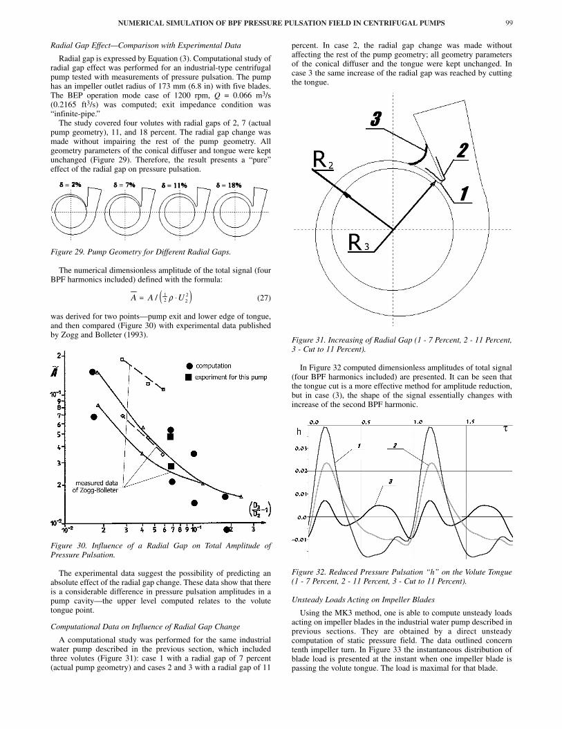
percent. In case 2, the radial gap change was made withoutaffecting the rest of the pump geometry; all geometry parametersof the conical diffuser and the tongue were kept unchanged. Incase 3 the same increase of the radial gap was reached by cuttingthe tongue.
Figure 31. Increasing of Radial Gap (1 - 7 Percent, 2 - 11 Percent,3 - Cut to 11 Percent).
In Figure 32 computed dimensionless amplitudes of total signal(four BPF harmonics included) are presented. It can be seen thatthe tongue cut is a more effective method for amplitude reduction,but in case (3), the shape of the signal essentially changes withincrease of the second BPF harmonic.
Figure 32. Reduced Pressure Pulsation “h” on the Volute Tongue(1 - 7 Percent, 2 - 11 Percent, 3 - Cut to 11 Percent).
Unsteady Loads Acting on Impeller Blades
Using the MK3 method, one is able to compute unsteady loadsacting on impeller blades in the industrial water pump described inprevious sections. They are obtained by a direct unsteadycomputation of static pressure field. The data outlined concerntenth impeller turn. In Figure 33 the instantaneous distribution ofblade load is presented at the instant when one impeller blade ispassing the volute tongue. The load is maximal for that blade.
( )A A U= ⋅/ 12 2
2ρ

Figure 33. Unsteady Loads Acting on Impeller Blades.
In Figure 33 the load acting on the volute casing is shown aswell, but these data have only qualitative significance as the currentversion of the DVM method has no possibility of accuratelycalculating loads acting on the casing of pump.
Time curves of radial and tangential forces acting on differentblades are presented in Figure 34 and Figure 35. A minus signshows that these forces act against a positive direction of velocities.It can be stated that the radial and tangential force has a maximumwhen a blade is passing the volute tongue.
Figure 34. Radial Load Acting on Different Impeller Blades.
The next blade has a minimal load at that moment. Behavior ofthe radial and tangential force is similar but amplitudes differ.Radial force changes from 300 N to 1300 N and tangential forcechanges from 120 N to 600 N. With such data, it is possible toestimate the pump power and vibration of the rotor due tohydraulic forces.
Figure 35. Tangential Load Acting on Different Impeller Blades.
Effect of Impeller Geometry Change—Computational Prediction
Influence of intermediary short blades was computationallystudied on the base of a new pump under development. Six typesof impeller geometry include five long blades (impeller 3), fivelong and five short blades positioned axisymmetrically at theimpeller exit (impeller 4), the same number of long and shortblades but positioned nonaxisymmetrically at the impeller exit(impeller 5), and other types with the same number of blades(impeller 6, 7, and 8). All computations were completed for thesame pump casing of 30 percent radial gap and the same operationparameters. “Infinite-pipe” condition was defined at the pump exit.
Impeller Geometry Change
The effect of Coriolis forces and secondary flows on parametersof flow in a blade channel of a centrifugal impeller is distributednonuniformly. Along the angle coordinate the relative velocity andflow angle are higher near the pressure side of the blade channel.Near the suction side of the blade the low energy zone is formed.The task was to act on the low energy zone of flow withintermediary shortened blades.
For better understanding of the impeller geometry change,Figure 36 shows consecutive changes in geometry by addingdifferent intermediary profiles to the long profile 3. The inlet edgeof the short blade penetrates into the low energy zone. The exitblade angle is altered as well to obtain a more optimal result.Profile 7 gave the best result in reduction of BPF pressurepulsation. Profile 3 of the long blade was unchanged for all casescomputed.
Figure 36. Change of Impeller Geometry by Adding Splitters.
Distribution of Flow Parametersalong the Blade Channel Span
Distributions of radial and tangential velocity components alongthe blade span between two long blades shows a considerable
PROCEEDINGS OF THE 19TH INTERNATIONAL PUMP USERS SYMPOSIUM100
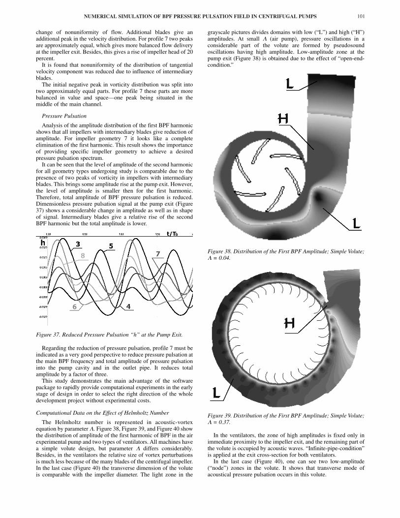
NUMERICAL SIMULATION OF BPF PRESSURE PULSATION FIELD IN CENTRIFUGAL PUMPS 101
change of nonuniformity of flow. Additional blades give anadditional peak in the velocity distribution. For profile 7 two peaksare approximately equal, which gives more balanced flow deliveryat the impeller exit. Besides, this gives a rise of impeller head of 20percent.
It is found that nonuniformity of the distribution of tangentialvelocity component was reduced due to influence of intermediaryblades.
The initial negative peak in vorticity distribution was split intotwo approximately equal parts. For profile 7 these parts are morebalanced in value and space—one peak being situated in themiddle of the main channel.
Pressure Pulsation
Analysis of the amplitude distribution of the first BPF harmonicshows that all impellers with intermediary blades give reduction ofamplitude. For impeller geometry 7 it looks like a completeelimination of the first harmonic. This result shows the importanceof providing specific impeller geometry to achieve a desiredpressure pulsation spectrum.
It can be seen that the level of amplitude of the second harmonicfor all geometry types undergoing study is comparable due to thepresence of two peaks of vorticity in impellers with intermediaryblades. This brings some amplitude rise at the pump exit. However,the level of amplitude is smaller then for the first harmonic.Therefore, total amplitude of BPF pressure pulsation is reduced.Dimensionless pressure pulsation signal at the pump exit (Figure37) shows a considerable change in amplitude as well as in shapeof signal. Intermediary blades give a relative rise of the secondBPF harmonic but the total amplitude is lower.
Figure 37. Reduced Pressure Pulsation “h” at the Pump Exit.
Regarding the reduction of pressure pulsation, profile 7 must beindicated as a very good perspective to reduce pressure pulsation atthe main BPF frequency and total amplitude of pressure pulsationinto the pump cavity and in the outlet pipe. It reduces totalamplitude by a factor of three.
This study demonstrates the main advantage of the softwarepackage to rapidly provide computational experiments in the earlystage of design in order to select the right direction of the wholedevelopment project without experimental costs.
Computational Data on the Effect of Helmholtz Number
The Helmholtz number is represented in acoustic-vortexequation by parameter Λ. Figure 38, Figure 39, and Figure 40 showthe distribution of amplitude of the first harmonic of BPF in the airexperimental pump and two types of ventilators. All machines havea simple volute design, but parameter Λ differs considerably.Besides, in the ventilators the relative size of vortex perturbationsis much less because of the many blades of the centrifugal impeller.In the last case (Figure 40) the transverse dimension of the voluteis comparable with the impeller diameter. The light zone in the
grayscale pictures divides domains with low (“L”) and high (“H”)amplitudes. At small Λ (air pump), pressure oscillations in aconsiderable part of the volute are formed by pseudosoundoscillations having high amplitude. Low-amplitude zone at thepump exit (Figure 38) is obtained due to the effect of “open-end-condition.”
Figure 38. Distribution of the First BPF Amplitude; Simple Volute;Λ = 0.04.
Figure 39. Distribution of the First BPF Amplitude; Simple Volute;Λ = 0.37.
In the ventilators, the zone of high amplitudes is fixed only inimmediate proximity to the impeller exit, and the remaining part ofthe volute is occupied by acoustic waves. “Infinite-pipe-condition”is applied at the exit cross-section for both ventilators.
In the last case (Figure 40), one can see two low-amplitude(“node”) zones in the volute. It shows that transverse mode ofacoustical pressure pulsation occurs in this volute.
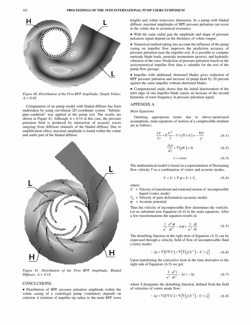
Figure 40. Distribution of the First BPF Amplitude; Simple Volute;Λ = 0.48.
Computation of air pump model with bladed diffuser has beenundertaken by using curvilinear 2D coordinate system. “Infinite-pipe-condition” was applied at the pump exit. The results areshown in Figure 41. Although Λ = 0.14 in this case, the pressurepulsation field is produced by interaction of acoustic wavesoutgoing from different channels of the bladed diffuser. Due toamplification effect, maximal amplitude is found within the voluteand outlet part of the bladed diffuser.
Figure 41. Distribution of the First BPF Amplitude; BladedDiffuser; Λ = 0.14.
CONCLUSIONS
• Distribution of BPF pressure pulsation amplitude within thevolute casing of a centrifugal pump (ventilator) depends oncriterion Λ (relation of impeller tip radius to the main BPF wave
length) and volute transverse dimension. In a pump with bladeddiffuser, maximal amplitudes of BPF pressure pulsation can occurin the volute due to acoustical resonance.
• With the same radial gap the amplitude and shape of pressurepulsation signal depend on the thickness of volute tongue.
• Numerical method taking into account the influence of the pumpcasing on impeller flow improves the prediction accuracy ofpressure pulsation near the impeller exit. It is possible to computeunsteady blade loads, unsteady momentum (power), and hydraulicvibration of the rotor. Prediction of pressure pulsation based on theaxisymmetrical impeller flow data is valuable for the rest of thepump flow passage.
• Impeller with additional shortened blades gives reduction ofBPF pressure pulsation and increase of pump head by 20 percentagainst the same impeller without shortened blades.
• Computational study shows that the initial deterioration of theinlet edge of one impeller blade causes an increase of the secondharmonic of rotor frequency in pressure pulsation signal.
APPENDIX A
Main Equations
Omitting appropriate terms due to above-mentionedassumptions, main equations of motion of a compressible mediumare as follows:
(A-1)
(A-2)
(A-3)
The mathematical model is based on a representation of fluctuatingflow velocity V as a combination of vortex and acoustic modes,
(A-4)
where:U = Velocity of transitional and rotational motion of incompressible
liquid (vortex mode)Va = Velocity of pure deformation (acoustic mode)ϕ = Acoustic potential
Thus the velocity of incompressible flow determines the vorticity.Let us substitute now Equation (A-4) in the main equations. Aftera few transformations the equation results in:
(A-5)
The disturbing function in the right term of Equation (A-5) can beexpressed through a velocity field of flow of incompressible fluid(vortex mode):
(A-6)
Upon transferring the convective term in the time derivative to theright side of Equation (A-5) we get:
(A-7)
where S designates the disturbing function, defined from the fieldof velocities of vortex mode flow:
(A-8)
PROCEEDINGS OF THE 19TH INTERNATIONAL PUMP USERS SYMPOSIUM102
( )∂∂ ρV
t
VV
P+ ∇ − ∇ × ∇ × = − ∇2
2V
( )∂ ρ∂
ρt
V+ ∇ = 0
s const=
V U U Va= + ∇ = +ϕ
1 12
2
2 2a
d
dt a
dj
dt
ϕ ϕ− =∆
( ) ( )( )− = ∇ ∇ = ∇ ∇ − ×∆ j U U U U12
2 ζ
12
2
2a
d i
dti j− = −∆ ∆
( ) ( )( )− = ∇ ∇ = ∇ ∇ − ×∆ j U U U U12
2 ζ

NUMERICAL SIMULATION OF BPF PRESSURE PULSATION FIELD IN CENTRIFUGAL PUMPS 103
and K the convective term:
(A-9)
Let us proceed now to dimensionless variables. For the spacescale and the characteristic velocity we shall take the pitch ofworking cascade l2 and the peripheral velocity u2 at the exit diameterof the impeller. Then the dimensionless quantities are as follows:
(A-10)
Substituting Equation (A-10) into the Equation (A-7), we get:
(A-11)
Parameter Λ = is the dimensionless similarity criterion of thegiven problem.
As a rule, in pumps Λ < 0.3. Therefore in Equation (A-11) theterm Λ2K is at least by an order of magnitude smaller than S.
Thus, for low harmonics of BPF pressure pulsations it ispossible to drop the convective members in the wave equation:
(A-12)
For an undisturbed flow ϕ = 0 and:
(A-13)
The functions i and j can be expressed through mean and pulsatorycomponent:
(A-14)
The amplitude of pressure pulsation in the pump is by an orderof magnitude lower than the mean undisturbed pressure. Thus forenthalpy oscillations it is possible to write approximately:
(A-15)
Similarly for oscillations of the function g we obtain:
(A-16)
The last expression shows oscillations produced bynonstationary vortex motion of the medium (in the incompressiblemotion)—so-called “pseudosound.” Considering the formulaegiven by Equation (A-13), Equation (A-14), and Equation (A-15),we obtain from Equation (A-12) an equation of pressureoscillations (due to acoustical and vortex motion):
(A-17)
where S~′ = � ∆g is the nonstationary part of the function S.
Solution of Equation (A-17) is divided into two parts—computation of the incompressible flow for the determination ofthe disturbing function and solution of an inhomogeneous waveequation for the determination of h.
Discrete Vortex Method
The DVM concept is based on three main postulates:
• Turbulence is a vortices’ motion (kinematics and transformation).
• In relation to our problem vortices mainly appear because offlow breaks from sharp edges and due to the wall layer separation(flow break).
• The transition from a deterministic flow to the turbulent oneresults in loss of stability of vortex structures (important for futuresimulations of turbulence pressure pulsation).
Physical Meaning of DVM
The fundamental formulation of DVM consists in thetransformation of a continuous vortex sheet (tangential break) todistribution of discrete vortices.
The surface of tangential flow break (Figure A-1) is the limitingcase for a vortex layer (sheet) with a vortex density γ = VS2 � VS1.As P1 = P2 and Vn2 = Vn1, centers of “elementary” vortices thatform the vortex sheet, move at the velocity of flow, the circulationalong a segment of sheet is constant. It is thus possible to replacethe sheet with the set of discrete vortices of constant intensity:
(A-18)
Figure A-1. Tangential Flow Break.
These are so-called free discrete vortices. They move with the flow.The physical meaning of the vortex is very straightforward:
following Stokes we can obtain:
(A-19)
The velocity at a point α can be found from relations:
(A-20)
Intensity of the wall vortices is derived from the condition ofimpenetrability and condition of constant circulation (Thompsontheorem). When finding Γj and Γk on S and σ it is possible to findthe potential of flow and velocity field.
Criteria of Flow Separation
In the separated flow, it is necessary to define criteria of flowseparation that follows the vortex generation (Figure A-2).
Under flow separation, we mean the process when the liquiddetaches from the wall with a nonzero velocity. Therefore, the Sand σ are tangent at the flow break point. At this point between σand S, the velocity of liquid is equal to the velocity of motion of thebreak point.
The velocity of a free discrete vortex roll off is γ*/2 where γ* isthe vorticity on σ at the break point.
Λ ∆22
2
∂∂
~
~~ ~ ~i
ti S− =
~ ~i j0 0=
~ ~;
~ ~i i h j j g= + = +0 0
( )h
P P
u
P
u≈
−= ′0
0 22
0 22ρ ρ
gP
uv≈ ′
ρ0 22
Λ ∆ Λ22
2
2∂∂
~
~~ ~ ~ ~i
ti S K− = −
Γ k dl= ∫ γ
Γkll dv
AAl
dv Vdl rotVdA dA l= = = =∫∫∫∫∫� �
2 ω γ
Uy y
r
Ux x
r
xa ka r
akk
ya ka r
akk
=−
= −−
∑
∑
1
2
1
2
2
2
π
π
Γ
Γ
~ ;~
;~
;~
xx
lU
U
ut
ti
i
ulu
= = = =2 2 2
222
Λ ∆ Λ22
2
2∂∂
~
~~ ~ ~ ~i
ti S K− = −
( )( )K Udi
dtU U i= ∇
+ ∇ ∇2
u2a
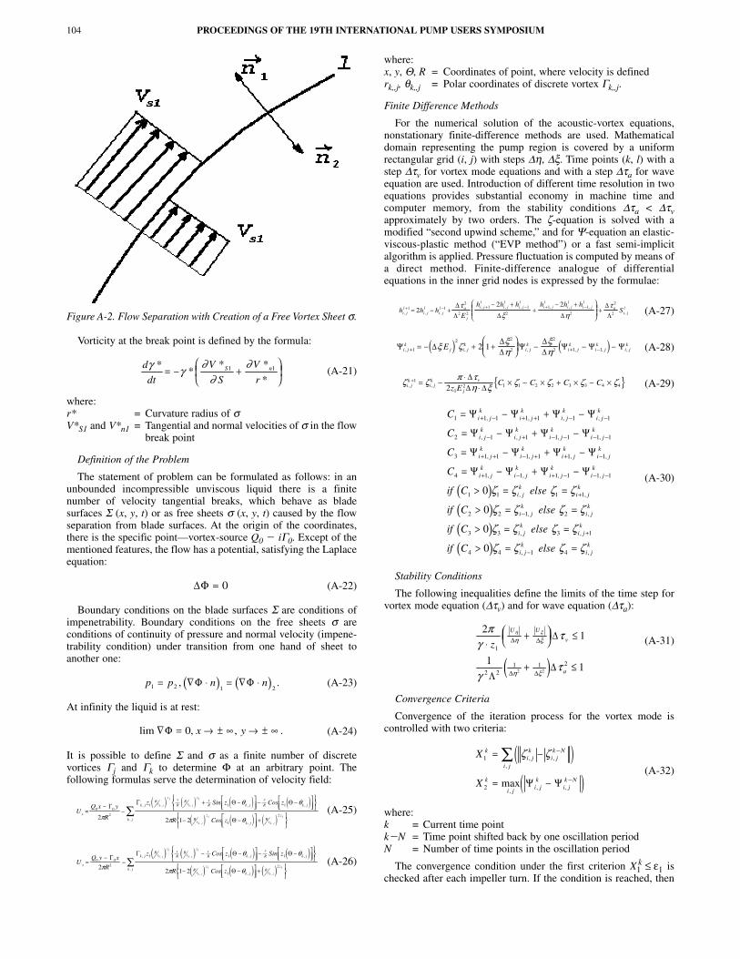
Figure A-2. Flow Separation with Creation of a Free Vortex Sheet σ.
Vorticity at the break point is defined by the formula:
(A-21)
where:r* = Curvature radius of σV*S1 and V*n1 = Tangential and normal velocities of σ in the flow
break point
Definition of the Problem
The statement of problem can be formulated as follows: in anunbounded incompressible unviscous liquid there is a finitenumber of velocity tangential breaks, which behave as bladesurfaces Σ (x, y, t) or as free sheets σ (x, y, t) caused by the flowseparation from blade surfaces. At the origin of the coordinates,there is the specific point—vortex-source Q0 � iΓ0. Except of thementioned features, the flow has a potential, satisfying the Laplaceequation:
(A-22)
Boundary conditions on the blade surfaces Σ are conditions ofimpenetrability. Boundary conditions on the free sheets σ areconditions of continuity of pressure and normal velocity (impene-trability condition) under transition from one hand of sheet toanother one:
(A-23)
At infinity the liquid is at rest:
(A-24)
It is possible to define Σ and σ as a finite number of discretevortices Γj and Γk to determine Φ at an arbitrary point. Thefollowing formulas serve the determination of velocity field:
(A-25)
(A-26)
where:x, y, Θ, R = Coordinates of point, where velocity is definedrk,,j, θk,,j = Polar coordinates of discrete vortex Γk,,j.
Finite Difference Methods
For the numerical solution of the acoustic-vortex equations,nonstationary finite-difference methods are used. Mathematicaldomain representing the pump region is covered by a uniformrectangular grid (i, j) with steps ∆η, ∆ξ. Time points (k, l) with astep ∆τv for vortex mode equations and with a step ∆τa for waveequation are used. Introduction of different time resolution in twoequations provides substantial economy in machine time andcomputer memory, from the stability conditions ∆τa < ∆τvapproximately by two orders. The ζ-equation is solved with amodified “second upwind scheme,” and for Ψ-equation an elastic-viscous-plastic method (“EVP method”) or a fast semi-implicitalgorithm is applied. Pressure fluctuation is computed by means ofa direct method. Finite-difference analogue of differentialequations in the inner grid nodes is expressed by the formulae:
(A-27)
(A-28)
(A-29)
(A-30)
Stability Conditions
The following inequalities define the limits of the time step forvortex mode equation (∆τv) and for wave equation (∆τa):
(A-31)
Convergence Criteria
Convergence of the iteration process for the vortex mode iscontrolled with two criteria:
(A-32)
where:k = Current time pointk�N = Time point shifted back by one oscillation periodN = Number of time points in the oscillation period
The convergence condition under the first criterion X1k ≤ ε1 is
checked after each impeller turn. If the condition is reached, then
PROCEEDINGS OF THE 19TH INTERNATIONAL PUMP USERS SYMPOSIUM104
( ) ( )p p n n1 2 1 2= ∇Φ ⋅ = ∇Φ ⋅, .
lim , , .∇Φ = → ± ∞ → ± ∞0 x y
( ) ( ) ( ) ( )( ) ( ) ( )
UQ x y
R
z Sin z Cos z
R Cos zx
k jR
r
z y
RR
r
zxR k j
y
R k j
Rr
z
k jR
r
zk j
k j k j
k j k j
=−
−+ −
− −
− −
+
∑0 0
2
1 1 1
1
22 2 1 2
1 1
1 1
Γ Γ Θ Θ
Θπ
θ θ
π θ
, , ,
,,
, ,
, ,
( ) ( ) ( ) ( )( ) ( ) ( )
UQ y x
R
z Cos z Sin z
R Cos zy
k jR
r
zxR
Rr
zxR k j
y
R k j
Rr
z
k jR
r
zk j
k j k j
k j k j
=−
−− −
− −
− −
+
∑0 02
1 1 1
1
222 1 2
1 1
1 1
Γ Γ Θ Θ
Θπ
θ θ
π θ
, , ,
,,
, ,
, ,
h h hE
h h h h h hSi j
li jl
i jl a
j
i jl
i jl
i jl
i jl
i jl
i jl
ai jl
, , ,
, , , , , ,
,+ − + − + −= − +
− ++
− +
+1 1
2
2 2
1 1
2
1 1
2
2
222 2∆
Λ ∆ ∆∆Λ
τξ η
τ
∆Φ = 0
( ) ( )Ψ ∆∆∆ Ψ
∆∆ Ψ Ψ Ψi j
kj i j
ki jk
i jk
i jk
i jkE, , , , , ,+ + −= − + +
− − −1
2 2
2
2
2 1 12 1ξ ζ ξη
ξη
{ }ζ ζ π τη ξ ζ ζ ζ ζi j
ki jk v
jz EC C C C, ,
+ = − ⋅⋅ × − × + × − ×1
12 1 1 2 2 3 3 4 42
∆∆ ∆
C
C
C
C
if
i jk
i jk
i jk
i jk
i jk
i jk
i jk
i jk
i jk
i jk
i jk
i jk
i jk
i jk
i jk
i jk
1 1 1 1 1 1 1
2 1 1 1 1 1 1
3 1 1 1 1 1 1
4 1 1 1 1 1 1
= − + −
= − + −
= − + −
= − + −
+ − + + − −
− + − − − −
+ + − + + −
+ − + − − −
Ψ Ψ Ψ Ψ
Ψ Ψ Ψ Ψ
Ψ Ψ Ψ Ψ
Ψ Ψ Ψ Ψ
, , , ,
, , , ,
, , , ,
, , , ,
( )( )( )( )
C else
if C else
if C else
if C else
i jk
i jk
i jk
i jk
i jk
i jk
i jk
i jk
1 1 1 1
2 2 1 2
3 3 3 1
4 4 1 4
0
0
0
0
> = =
> = =
> = =
> = =
+
−
+
−
ζ ζ ζ ζ
ζ ζ ζ ζ
ζ ζ ζ ζ
ζ ζ ζ ζ
, ,
, ,
, ,
, ,
( )
21
11
1
2 21 1 2
2 2
πγ
τ
γτ
η ξ
η ξ
η ξ
⋅+
≤
+ ≤
z
U U
v
a
∆ ∆
∆ ∆
∆
Λ∆
( )( )
X
X
ki jk
i jk N
i j
k
i ji jk
i jk N
1
2
= −
= −
−
−
∑ ζ ζ, ,,
,, ,max Ψ Ψ
d
dt
V
S
V
rS nγ γ ∂
∂∂*
** *
*= − +
1 1
NUMERICAL SIMULATION OF BPF PRESSURE PULSATION FIELD IN CENTRIFUGAL PUMPS 105
X2k is calculated for the second check—X2
k ≤ ε2 (ε1, ε2 areconstants). The convergence condition for the wave solution isX3
k ≤ ε3 (ε3 is a constant) where:
(A-33)
where:l = Current time pointl�M = Time point shifted back by one oscillation periodM = Number of time points in the oscillation period
REFERENCES
Chen, Y. N., 1961, “Water-Pressure Oscillations in the VoluteCasings of Storage Pumps,” Sulzer Technical Review,Research Number.
Chu, S., Dong, R., and Katz, J., 1993, “The Effect of Blade-TongueInteractions on the Flow Structure, Pressure Fluctuations andNoise Within a Centrifugal ump,” ump Noise and Vibration,First International Symposium, Clamart, France, pp. 13-34.
Croba, D. and Kueny, J. L., 1992, “Unsteady Flow Computation ina Centrifugal ump Coupling of the Impeller and the Volute,”Fan Noise, An International INCE Symposium, Senlis, France,pp. 221-228.
Croba, D., Kueny, J. L, Hureau, F., and Kermarec, J., “Numericaland Experimental Unsteady Flow Analysis in CentrifugalPumps,” Impeller and Volute Interaction, Pump Noise andVibration, First International Symposium, Clamart, France, pp.111-119.
Joffe, T. L. and Panchenko V. I., 1972, “To the Study of Influenceof the Number of Impeller Blades of a Hydrodynamic Machineon Its Vibration-Acoustic Characteristics,” Mashinovedeniye,(1).
Sukup, J. K., 1974, “To the Problem of Pressure Pulsations in theRadial Centrifugal Pump,” Translation No. 30915, Moscow,Russia (All-Union Center of Translations).
Sukup, J. K., 1975, “To the Problem of Pressure Pulsations in theCentrifugal Pump,” Translation No. 62734, Moscow, Russia(All-Union Center of Translations).
Thompson, M. C., Hourigan, K., and Stokes, A. N., 1992,“Prediction of the Noise Generation in a Centrifugal Fan bySolution of the Acoustic Wave Equation,” Fan Noise, AnInternational INCE Symposium, Senlis, France, pp. 197-204.
Tourret, J., Kamga, M., Godefroi, B., Pluviose, M., Kermarec, J.,and Bertinier, M., 1991, “Hydraulic Noise Generation Studiesin Centrifugal Turbomachine Through Visualization of the NonStationary Pressure Field in the Volute and in the Impeller,”ASME/Reprinted from FED 128, Experimental and NumericalFlow Visualization, Editors: B. Khalighi, etc./Book No. 1991,pp. 239-246.
Zogg, H. and Bolleter, U., 1993, “Generation and Propagation ofHydraulic Noise in Centrifugal Pumps,” Pump Noise andVibration, First International Symposium, Clamart, France,Proceedings, pp. 263-270.
Additional information for the specialized software package usedin this paper can be retrieved from the website: www.pump-harmony.ru
BIBLIOGRAPHY
Blokhintsev, D. I., 1981, “Acoustics of the Heterogeneous MovingMedium, Science, Moscow, Russia.
Crow, S. C., 1970, “Aerodynamic Sound Emission as a Singularerturbation roblem,” Studies in Applied Mathematics, XLIX,(1).
ISO 3740, 2000, “Acoustics—Determination of Sound PowerLevels of Noise Sources—Guidelines for the Use of BasicStandards,” International Organization for Standardization,Geneva, Switzerland.
Landau, L. D. and Lifschitz, Y. E. M., 1954, ContinuumMechanics, Moscow, Russia: State Publishing House ofTechnical and Theoretical Literature.
Ovsyannikov, B. V. and Timouchev, S. F., 1986, “About theCalculation of Pressure Pulsations on Blade PassingFrequencies in the Outlet of Centrifugal Pumps,” In theCollection: “Problems of the Theory of Engines During EngineTesting,” Moscow Aviation Institute (Chair 202).
Timouchev, S. F., 1999, “Numerical Method and Software Packagefor Prediction of Pressure Pulsation in Centrifugal Ventilators,”Forum Acusticum ‘99, The First Joint Meeting of EAA andASA, Berlin, Germany, In a collection of abstracts.
Timouchev, S. F. and Illichov, K. P., 1995, “2D NumericalSimulation of Unsteady Pressure Field in Centrifugal Pumps,”Euro-Noise ‘95, An International INSE Symposium, Lyon,France, Proceedings, 3, pp. 905-910.
Timushev, S. F. and Nedashkovsky, A. K, 1995, “Computationaland Experimental Study of Acoustical Resonances inCentrifugal Pump Working Cavity,” Pump Noise andVibration, First International Symposium, Clamart, France, pp.271-277.
Timushev, S. F. and Ovsyannikov, B.V., 1992, “PressureFluctuation Numerical Simulation in a Centrifugal PumpVolute Casing,” Journal de Physique IV, 2, Second FrenchConference on Acoustics, Arcachon, France, pp. 619-622.
Timouchev, S. F. and Tourret, J., 1999, “Numerical Prediction ofBPF Pressure Pulsation in Centrifugal Pumps and Ventilatorswith Harmony MK1, MK2 Software Packages,” Ninth IAHRWG International Meeting on the Behavior of HydraulicMachinery under Steady Oscillatory Conditions, Brno, CzechRepublic, In a collection of papers.
Timouchev, S. F. and Tourret, J., 2000, “Harmony Software forLow Noise Design of Centrifugal Ventilators of TransportMachines,” Twenty-Ninth International Congress on NoiseControl Engineering—InterNoise 2000, Nice, France,Proceedings, 6, pp. 3833-3836.
Timouchev, S. F., Nedashkovsky, A., and Pavic, G., 1997,“Computational Study of the Acoustic Impedance Effect onBPF Pressure Oscillations in Centrifugal Pumps.” EighthIAHR WG International Meeting on the Behavior of HydraulicMachinery under Steady Oscillatory Conditions, Chatou,France, In a collection of papers.
( ) ( )X h h hk
i ji jl
i jl M
i ji j30= − −max / max
,, ,
,,

PROCEEDINGS OF THE 19TH INTERNATIONAL PUMP USERS SYMPOSIUM106