Numerical simulation for the free surface flow around a complex ship hull form at different Froude...
7
ORIGINAL ARTICLE Numerical simulation for the free surface flow around a complex ship hull form at different Froude numbers Y.M. Ahmed Naval Architecture and Marine Engineering Department, Alexandria University, Alexandria, Egypt Received 23 October 2010; accepted 8 January 2011 Available online 6 October 2011 KEYWORDS DTMB; CFD; Free surface; Wave; CFX; Resistance; Numerical Abstract The incompressible turbulent free surface flow around the complex hull form of the DTMB 5415 model at two different speeds has been numerically simulated using the RANSE code CFX. The Volume of Fluid method (VOF) has been used with CFX for capturing the free surface flow around the ship model at the two speeds. The simulation conditions are the ones for which experimental and numerical results exist. The standard k–e turbulence model has been used in CFX code. The grid generator ICEM CFD has been used for building the hybrid grid for the RANSE code solver. The results compare well with the available experimental and numerical data. ª 2011 Faculty of Engineering, Alexandria University. Production and hosting by Elsevier B.V. All rights reserved. 1. Introduction Studying the pattern of waves generated by a ship moving through the water is one of the most important objectives in ship hydrodynamics, due to its importance in the design process. The waves produced by a ship in motion can radiate at great distances away from the ship. Furthermore, these waves contain energy that must be dissipated to the surround- ing fluid. The ship experiences an opposing force to its move- ment; one of its components is known as the wave making resistance, this being one of the most important components of the ship resistance. Potential and turbulent flow methods are being intensively used for investigating and simulating the flow pattern around ships. Typically, the potential flow codes based on the bound- ary element method (BEM) [1,2] are commonly used to study the ship waves on the free surface and to investigate the inter- action between bulbous bow and forward shoulder waves. The effects of fluid viscosity are neglected in this case and the flow computation is relatively simple, quick, and accurate. The ship hull and the water surface in the potential flow codes are usu- ally discretized using triangular or quadrilateral panels; hence the flow is computed by solving the Laplace equation. For simulating wave resistance problems in potential flow codes, the Rankine source method [3,4] is considered to be the most widely used technique in this case. The free surface boundary condition can be incorporated successfully in the simulation process based on a so-called double model solution, E-mail address: [email protected] 1110-0168 ª 2011 Faculty of Engineering, Alexandria University. Production and hosting by Elsevier B.V. All rights reserved. Peer review under responsibility of Faculty of Engineering, Alexandria University. doi:10.1016/j.aej.2011.01.017 Production and hosting by Elsevier Alexandria Engineering Journal (2011) 50, 229–235 Alexandria University Alexandria Engineering Journal www.elsevier.com/locate/aej www.sciencedirect.com
-
Upload
yasser-ahmed -
Category
Engineering
-
view
151 -
download
3
Transcript of Numerical simulation for the free surface flow around a complex ship hull form at different Froude...
Alexandria Engineering Journal (2011) 50, 229–235
Alexandria University
Alexandria Engineering Journal
www.elsevier.com/locate/aejwww.sciencedirect.com
ORIGINAL ARTICLE
Numerical simulation for the free surface flow around
a complex ship hull form at different Froude numbers
Y.M. Ahmed
Naval Architecture and Marine Engineering Department, Alexandria University, Alexandria, Egypt
Received 23 October 2010; accepted 8 January 2011
Available online 6 October 2011
E-
11
Pr
Pe
U
do
KEYWORDS
DTMB;
CFD;
Free surface;
Wave;
CFX;
Resistance;
Numerical
mail address: yahmed@alex.
10-0168 ª 2011 Faculty o
oduction and hosting by Els
er review under responsibility
niversity.
i:10.1016/j.aej.2011.01.017
Production and h
edu.eg
f Engine
evier B.V
of Facu
osting by E
Abstract The incompressible turbulent free surface flow around the complex hull form of the
DTMB 5415 model at two different speeds has been numerically simulated using the RANSE code
CFX. The Volume of Fluid method (VOF) has been used with CFX for capturing the free surface
flow around the ship model at the two speeds. The simulation conditions are the ones for which
experimental and numerical results exist. The standard k–e turbulence model has been used in
CFX code. The grid generator ICEM CFD has been used for building the hybrid grid for the
RANSE code solver. The results compare well with the available experimental and numerical data.ª 2011 Faculty of Engineering, Alexandria University. Production and hosting by Elsevier B.V.
All rights reserved.
1. Introduction
Studying the pattern of waves generated by a ship movingthrough the water is one of the most important objectives in
ship hydrodynamics, due to its importance in the designprocess. The waves produced by a ship in motion can radiateat great distances away from the ship. Furthermore, these
waves contain energy that must be dissipated to the surround-
ering, Alexandria University.
. All rights reserved.
lty of Engineering, Alexandria
lsevier
ing fluid. The ship experiences an opposing force to its move-
ment; one of its components is known as the wave makingresistance, this being one of the most important componentsof the ship resistance.
Potential and turbulent flow methods are being intensivelyused for investigating and simulating the flow pattern aroundships. Typically, the potential flow codes based on the bound-ary element method (BEM) [1,2] are commonly used to study
the ship waves on the free surface and to investigate the inter-action between bulbous bow and forward shoulder waves. Theeffects of fluid viscosity are neglected in this case and the flow
computation is relatively simple, quick, and accurate. The shiphull and the water surface in the potential flow codes are usu-ally discretized using triangular or quadrilateral panels; hence
the flow is computed by solving the Laplace equation.For simulating wave resistance problems in potential flow
codes, the Rankine source method [3,4] is considered to be
the most widely used technique in this case. The free surfaceboundary condition can be incorporated successfully in thesimulation process based on a so-called double model solution,

Nomenclature
V velocity vector or speed of advance
q densityp pressureCp pressure coefficient = (p � p1)/0.5qV
2
CF frictional resistance coefficient = RF/0.5qAV2
CT total resistance coefficient = RT/0.5qAV2
RF frictional resistance forceRP pressure resistance force
RT total resistance force
Fn Froude number
L ship lengthra volume of fraction of phase fluid ala viscosity of the continuous phase aui = (u, v, w) velocity components in the directions of
xi = (x, y, z)tt turbulent kinematic viscosity = lt/qe turbulence eddy dissipation rate
Figure 1 The hull form of DTMB 5415 unit.
Table 1 Principal dimensions of DTMB 5415 [12].
Length 142.037 m
Beam 17.983 m
Draft 6.179 m
Wet surface area 2976.7 m2
Water plane area 1987.2 m2
Displacement 12901.6 m3
Block coefficient 0.506
Table 2 Test conditions for DTMB 5415 model scale [12].
Scale ratio 24.832
Length (L) 5.72 m
Draft (T) 0.248 m
Wet surface area 4.861 m2
Froude numbers 0.28 and 0.41
230 Y.M. Ahmed
which was proposed by Dawson [5]. Since then it has beenwidely applied as a practical method and many improvementshave been made to account for the nonlinearity of the free
surface physics [6].Modern viscous flow codes, which solve the RANSE, have
the ability to simulate efficiently the turbulent flow problems
around ships with and without free surface effects. These codescan produce relatively accurate results both for the flow fieldand for the ship resistance. Furthermore, the use of the viscouscodes is essential for investigating some flow characteristics
such as flow separation near the ship stern, where the flow pat-tern can only be predicted reasonably by viscous approaches.The numerical methods are used for solving governing fluid
equations with these codes, through discretization schemessuch as finite differences and finite volume methods.
Free surface problems such as the wave making problem
can be simulated with viscous flow codes depending onwhether the computational grid adapts to the shape or the po-sition of the free surface. Therefore, two major approaches
widely applied to the free surface computations are the so-called interface-tracking method, e.g., a moving mesh [7,8],and the interface-capturing method, e.g., the volume of fluidmethod (VOF) [9,10].
The mesh in the former method moves over an underlyingfixed Eulerian grid for tracking a free surface flow patternaround ship hull. This mesh only covers the domain involving
the water, where the free surface forms the upper boundary ofthe computational domain and is determined as part of thesolution. This approach can be applied for moving boundary
problems, but special treatments are required for simulatingproblems of large deformation such as breaking waves.
In the interface-capturing method, both air and water are
considered in the simulation and treated as two effective fluids.The numerical grids in this method are fixed in space, and thepredication of the free surface location is achieved by solvingan additional transport equation.
In this study, the incompressible free surface flow around theDTMB5415model has been studied using the finite volume flowcode CFX [11] at Fn = 0.28 and 0.41. The frictional resistance
and the pressure resistance (the viscous pressure resistance plusthe wave making resistance) coefficients of the model hull havebeen calculated numerically using the finite volume code.
The flow was taken to be steady in the RANSE code simu-lations. The standard k–e turbulence model was used in CFXsimulations. The predicted numerical results were comparedwith the available experimental and numerical results for the
complex hull form of the DTMB 5415 model at the two speeds.
2. Description of DTMB 5415 hull form
The model 5415 (Fig. 1) was conceived as a preliminary designfor a Navy surface combatant ca. 1980. The hull geometry in-cludes both a sonar dome and transom stern. Propulsion is
provided through twin open-water propellers driven by shaftssupported by struts.
The principal dimensions of the DTMB 5415 are listed in
Table 1 and the test conditions that are listed in Table 2 corre-spond to the model tests from the David Taylor Model Basin(DTMB) in Washington DC and the Istituto Nazionale perStudied Esperienze di Architettura Navale (INSEAN) in
Rome, Italy. Both computations and experiments are con-ducted in the bare hull condition.

Numerical simulation for the free surface flow around a complex ship hull form at different Froude numbers 231
3. Mathematical model
The mathematical description of the free surface flow in CFX
is based on the homogenous multiphase Eulerian–Eulerianfluid approach. Both fluids (water and air) in this approachshare the same velocity field and other relevant fields such astemperature, turbulence, etc., and they are separated by a dis-
tinct resolvable interface. The local equations governing themotion of an unsteady, viscous, incompressible fluid (either li-quid or gas) are the Navier–Stokes equations, which in a con-
servative formulation are given as:
o
otðqÞ þ o
oxi
ðquiÞ ¼ 0:0 ð1Þ
o
otðquiÞ þ
o
oxi
ðquiujÞ ¼ �op
oxi
þ o
oxi
ð�qu0iu0jÞ
þ o
oxj
louioxj
þ oujoxi
� 2
3dij
ouloxl
� �� �ð2Þ
where,
�qu0iu0j ¼ lt
ouioxj
þ oujoxi
� �� 2
3qkþ lt
ouioxi
� �dij ð3Þ
and
q ¼X2a¼1
raqa; l ¼X2a¼1
rala;X2a¼1
ra ¼ 1
The standard k–e turbulent model was used in CFX code,
where
qujokioxj
¼ o
oxi
lþ lt
rk
� �ok
oxi
� �þ Gk þ Gb � qe� YM ð4Þ
qujoeioxj
¼ o
oxi
lþ lt
rk
� �oeoxi
� �þ C1e
ekðGk þ C3eGbÞ � C2eq
e2
k
ð5Þ
where Gk, Gb and YM are the generation of turbulent kinetic
energy due the mean velocity gradients, the generation of tur-bulent kinetic energy due to buoyancy and the contribution ofthe fluctuating dilatation in compressible turbulence to the
overall dissipation rate. In this study the model constants have
Figure 2 Computational domai
taken the following values C1e = 1.45, C2e = 1.9, rk = 1.0
and re = 1.3.
4. Computational grid
The computational domain in this study extends for 1.5L infront of the ship hull, 2.5L behind the hull, 1.5L to the side
and 1.2L under the keel of the model. The air layer extends0.125L above the still water surface. The grid generator ofthe RANSE code (ICEM CFD) has been used for buildingthe required hybrid mesh for the code solver. The computa-
tional domain of the DTMB 5415 model (Fig. 2) has beenmeshed with structured hexahedral grid of 95971 elements,while the hull surface of the DTMB 5415 model and the region
around it have been meshed using unstructured tetrahedralgrid of 331924 elements (Fig. 3). The mesh was refined in thefree surface region in order to get a sharp free surface. Further-
more, for predicting accurate values for CP the mesh elementswere refined on and near the ship hull surface in order to cal-culate accurate pressure forces acting on the hull form at the
two Froude numbers. Finally, the space of the first grid fromthe hull is y+ � 25.
5. Boundary conditions and computational methods
The no-slip boundary condition is imposed on the hull surfaceof the DTMB 5415 model, that is, the fluid particles on the
body move with body velocity. The static pressure at the outletboundary was defined as a function of water volume fraction.Furthermore, the initial location of the free surface was im-
posed by defining the volume fraction functions of water andair at the inlet and outlet boundaries. The scalable wall func-tion was used with the turbulence model. The reference pres-
sure was set to an atmospheric pressure. Only the starboardside of the DTMB 5415 model hull was considered withCFX due to the symmetric properties of the problem underconsideration.
The flow was considered steady in CFX calculations, andthe finite volume method is used for the discretization process.The high resolution numerical scheme was used for discretizing
the advection terms. A linear interpolation scheme was usedfor interpolating the pressure, while the velocity was interpo-
n of the DTMB 5415 model.

Figure 3 Hybrid mesh for the DTMB 5415 model and its domain.
232 Y.M. Ahmed
lated using a trilinear numerical scheme. The results in thisstudy were obtained on one computer Pentium IV 2 GHzand 1 Gb RAM.
6. Results
The wave cuts along the hull surface of the DTMB 5415 model
at the two speeds are represented in Figs. 4 and 5. The compar-isons between the predicted results and the available experi-mental results show in general good agreement between the
results at the two speeds. However, the wave cut predictedby CFX at Fn = 0.41 is somewhat under predicted than that
-0.010
-0.005
0.000
0.005
0.010
0.015
0.020
-0.5 -0.4 -0.3 -0.2 -0.1 0x/L
z/L
Figure 4 Wave cut along the hull of th
-0.020
-0.010
0.000
0.010
0.020
0.030
0.040
-0.5 -0.4 -0.3 -0.2 -0.1 0
x/L
z/L
Figure 5 Wave cut along the hull of th
obtained from the experimental results, especially from nearly-0.3L to 0.5L. This may give a direct indication about therequirements of more unstructured tetrahedral mesh elementsaround the DTMB 5415 hull, which could not be attained
due to the limited computational power available.The comparison between the predicted wave pattern
around the hull form of the DTMB 5415 model by CFX, the
available experimental results [15] and the numerical resultsobtained from using the potential flow method [16] atFn = 0.28 (Fig. 6) shows the ability of CFX for predicting
nearly the same wave contours at the bow and the stern ofthe model. However, the calculated wave contours at the
0.1 0.2 0.3 0.4 0.5
EXP. [13]CFX
e DTMB 5415 model at Fn = 0.28.
0.1 0.2 0.3 0.4 0.5
EXP. [14]CFX
e DTMB 5415 model at Fn = 0.41.
y/L
0.7
0.6
0.5
0.4
0.3
0.2
0.1
0.0-1.0 0.0 1.0
x/L
x/L1.00.0-1.0
0.0
0.1
0.2
0.3
0.4
0.5
0.6
0.7
y/L
a
b
c
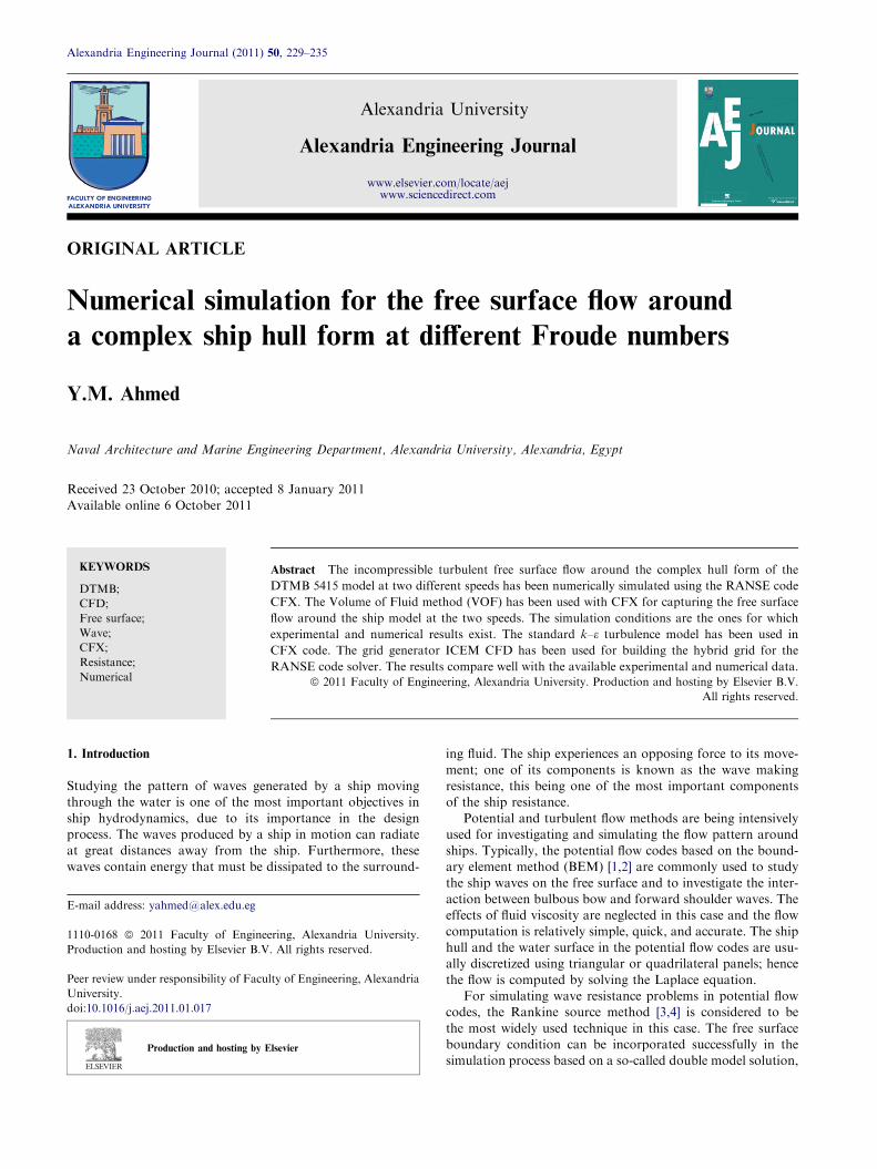
Figure 6 (a) Experimental wave contours at Fn = 0.28 [15], (b)
predicted wave contours at Fn = 0.28 (CFX), (c) predicted wave
contours by potential flow method at Fn = 0.28 [16].
Numerical simulation for the free surface flow around a complex ship hull form at different Froude numbers 233
mid region of the ship is different from the experimental andnumerical contours at this speed. This may refer to the diffi-culty in calculating the wave contours at this low Froude num-ber due to the small value of the wave making resistance in this
case. On the other hand, there is a good agreement betweenCFX results and the numerical results [16] for the wave con-
y/L
0.0-1.00.0
0.1
0.2
0.3
0.4
0.5
0.6
0.7
0.0
0.1
0.7
y/L
0.2
0.3
0.4
0.5
0.6
0.0-1.0
a
b
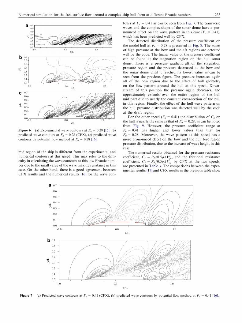
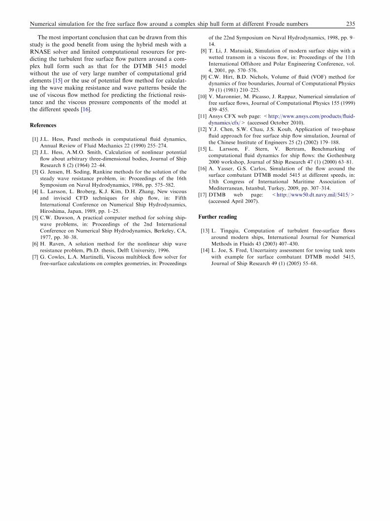
Figure 7 (a) Predicted wave contours at Fn = 0.41 (CFX), (b) pred
tours at Fn = 0.41 as can be seen from Fig. 7. The transverse
waves and the complex shape of the sonar dome have a pro-nounced effect on the wave pattern in this case (Fn = 0.41),which has been predicted well by CFX.
The detected distribution of the pressure coefficient on
the model hull at Fn = 0.28 is presented in Fig. 8. The zonesof high pressure at the bow and the aft regions are detectedwell by the code. The higher value of the pressure coefficient
can be found at the stagnation region on the hull sonardome. There is a pressure gradient aft of the stagnationpressure region and the pressure decreased at the bow and
the sonar dome until it reached its lowest value as can beseen from the previous figure. The pressure increases againaft of the bow region due to the effect of hull geometry
on the flow pattern around the hull at this speed. Down-stream of this position the pressure again decreases, andapproximately extends over the entire region of the hullmid part due to nearly the constant cross-section of the hull
in this region. Finally, the effect of the hull wave pattern onthe hull pressure distribution was detected well by the codeat the draft region.
For the other speed (Fn = 0.41) the distribution of Cp onthe hull is nearly the same as that of Fn = 0.28, as can be notedfrom Fig. 9. However, the pressure coefficient range at
Fn = 0.41 has higher and lower values than that forFn = 0.28. Moreover, the wave pattern at this speed has amore pronounced effect on the bow and the hull fore regionpressure distribution, due to the increase of wave height in this
case.The numerical results obtained for the pressure resistance
coefficient, CP ¼ RP=0:5qAV21, and the frictional resistance
coefficient, CF ¼ RF=0:5qAV21 by CFX at the two speeds,
are presented in Table 3. The comparisons between the exper-imental results [17] and CFX results in the previous table show
x/L1.0
1.0
x/L
icted wave contours by potential flow method at Fn = 0.41 [16].

Figure 8 Distribution of Cp on the hull surface of DTMB 5415 model at Fn = 0.28.
Figure 9 Distribution of Cp on the hull surface of DTMB 5415 model at Fn = 0.41.
Table 3 Experimental and numerical resistance components of the DTMB 5415 model.
Froude no. Coefficient Experimental results [17] CFX
Fn = 0.28 CF 2.880 · 10�3 2.995 · 10�3
CP 1.350 · 10�3 1.513 · 10�3
CT 4.230 · 10�3 4.384 · 10�3
Fn = 0.41 CF 2.806 · 10�3 2.738 · 10�3
CP 3.094 · 10�3 2.919 · 10�3
CT 5.900 · 10�3 6.075 · 10�3
234 Y.M. Ahmed
the ability of the RANSE code CFX in predicting accurate val-ues for the resistance coefficients at the two speeds.
7. Conclusions
The turbulent free surface flow around the DTMB 5415 modelhull at two Froude numbers has been simulated using the
RANSE code CFX. The wave profiles along the hull of themodel compared well against the available experimental resultsat the two speeds.
The results of CFX code show the ability of predicting
good results for the free surface wave pattern around the hullat Fn = 0.41, even with the need for more computationalgrid.
Numerical simulation for the free surface flow around a complex ship hull form at different Froude numbers 235
The most important conclusion that can be drawn from this
study is the good benefit from using the hybrid mesh with aRNASE solver and limited computational resources for pre-dicting the turbulent free surface flow pattern around a com-plex hull form such as that for the DTMB 5415 model
without the use of very large number of computational gridelements [15] or the use of potential flow method for calculat-ing the wave making resistance and wave patterns beside the
use of viscous flow method for predicting the frictional resis-tance and the viscous pressure components of the model atthe different speeds [16].
References
[1] J.L. Hess, Panel methods in computational fluid dynamics,
Annual Review of Fluid Mechanics 22 (1990) 255–274.
[2] J.L. Hess, A.M.O. Smith, Calculation of nonlinear potential
flow about arbitrary three-dimensional bodies, Journal of Ship
Research 8 (2) (1964) 22–44.
[3] G. Jensen, H. Soding, Rankine methods for the solution of the
steady wave resistance problem, in: Proceedings of the 16th
Symposium on Naval Hydrodynamics, 1986, pp. 575–582.
[4] L. Larsson, L. Broberg, K.J. Kim, D.H. Zhang, New viscous
and inviscid CFD techniques for ship flow, in: Fifth
International Conference on Numerical Ship Hydrodynamics,
Hiroshima, Japan, 1989, pp. 1–25.
[5] C.W. Dawson, A practical computer method for solving ship-
wave problems, in: Proceedings of the 2nd International
Conference on Numerical Ship Hydrodynamics, Berkeley, CA,
1977, pp. 30–38.
[6] H. Raven, A solution method for the nonlinear ship wave
resistance problem, Ph.D. thesis, Delft University, 1996.
[7] G. Cowles, L.A. Martinelli, Viscous multiblock flow solver for
free-surface calculations on complex geometries, in: Proceedings
of the 22nd Symposium on Naval Hydrodynamics, 1998, pp. 9–
14.
[8] T. Li, J. Matusiak, Simulation of modern surface ships with a
wetted transom in a viscous flow, in: Proceedings of the 11th
International Offshore and Polar Engineering Conference, vol.
4, 2001, pp. 570–576.
[9] C.W. Hirt, B.D. Nichols, Volume of fluid (VOF) method for
dynamics of free boundaries, Journal of Computational Physics
39 (1) (1981) 210–225.
[10] V. Maronnier, M. Picasso, J. Rappaz, Numerical simulation of
free surface flows, Journal of Computational Physics 155 (1999)
439–455.
[11] Ansys CFX web page: <http://www.ansys.com/products/fluid-
dynamics/cfx/> (accessed October 2010).
[12] Y.J. Chen, S.W. Chau, J.S. Kouh, Application of two-phase
fluid approach for free surface ship flow simulation, Journal of
the Chinese Institute of Engineers 25 (2) (2002) 179–188.
[15] L. Larsson, F. Stern, V. Bertram, Benchmarking of
computational fluid dynamics for ship flows: the Gothenburg
2000 workshop, Journal of Ship Research 47 (1) (2000) 63–81.
[16] A. Yasser, G.S. Carlos, Simulation of the flow around the
surface combatant DTMB model 5415 at different speeds, in:
13th Congress of International Maritime Association of
Mediterranean, Istanbul, Turkey, 2009, pp. 307–314.
[17] DTMB web page: <http://www50.dt.navy.mil/5415/>
(accessed April 2007).
Further reading
[13] L. Tingqiu, Computation of turbulent free-surface flows
around modern ships, International Journal for Numerical
Methods in Fluids 43 (2003) 407–430.
[14] L. Joe, S. Fred, Uncertainty assessment for towing tank tests
with example for surface combatant DTMB model 5415,
Journal of Ship Research 49 (1) (2005) 55–68.