
Numerical Simulation and Experimental Study of the ...volinsky/Spindle.pdfExperimental Study of the...
11
Send Orders for Reprints to [email protected] The Open Mechanical Engineering Journal, 2015, 9, 1293-1303 1293 1874-155X/15 2015 Bentham Open Open Access Numerical Simulation and Experimental Study of the Hydrostatic Spindle with Orifice Restrictors He Qiang 1 , Li Lili 1 , Ren Fengzhang *,2 and A. Volinsky Alex 3 1 Department of Mechanical Engineering, Anyang Institute of Technology, Anyang, 45500, China 2 School of Materials Science and Engineering, Henan University of Science and Technology, Luoyang 471003, China 3 Department of Mechanical Engineering, University of South Florida, Tampa FL 33620, USA Abstract: Based on the theory of hydrostatic bearings, this paper presents a study of replacing the rolling bearings in a cold drawing spindle with the liquid hydrostatic bearings. An unloading mechanism is designed, containing two hydrostatic radial bearings and a thrust bearing, according to the mechanical characteristics of the spindle. In this study, a mathematical model of the hydrostatic bearing oil pad is developed. The effects of the rotating speed on pressure and flow fields of the oil pad are simulated using the finite element analysis and verified experimentally. The pressure in all recesses decreases with the rotation speed. Oil velocity of the radial hydrostatic bearing recess increases with the rotation speed, while the fluid flow velocity has almost no correlation with the rotation speed of the thrust bearing. The numerical and experimental results of the pressure in the recesses are consistent, confirming the validity and feasibility of this design. Keywords: Orifice restrictor, hydrostatic spindle, design, numerical simulation, experimental study. 1. INTRODUCTION Bearings are indispensable key parts of all kinds of rotating machinery. Rolling bearings are quite popular among the designers because of the low friction coefficient, high transmission efficiency and standardization. However, rotary precision of the rolling friction pair bearing depends on the machining accuracy (precision of the rolling elements and the raceway), and the material. Thus, for the hollow cylindrical roller bearing it is hard to achieve the rotation accuracy better than 0.5 μm. The ability of the rolling bearing to withstand impact load is poor, let alone its high noise and vibration levels. The bearing operating life is short in the high speed and heavy load conditions. These are the main reasons why its service range is limited, especially when supporting high precision and high load spindles. Hydrostatic bearings have the advantages of low starting power, high rotary precision, wide application range, and suitability for a wide rotation speed range, good vibration resistance and long operating life. This is why they are extensively used in various kinds of machining applications. They can also meet the special requirements of machining precision and long service life. Due to these advantages, it’s important to study the impacts of hydrostatic bearing structure and oil. Analysis on flowing characteristic of fluid can quickly find the unreasonable design and provide the necessary theoretical support for the optimization design. Xiang *Address correspondence to this author at the School of Materials Science and Engineering, Henan University of Science and Technology, Luoyang 471003, China; Tel/Fax: +86-372-13213250061; E-mail : [email protected] Kefeng [1] with the help of fluent software numerical simulates the closing process of shuttle check valve. Jianmin Xu [2] analyzes the flow field of automotive exhaust system based on computational fluid dynamics and provides a theoretical basis for designing complex exhaust system. Guochang Zhao [3] researches on flow and temperature fields in aircraft engines. Kuiyang Wang [4] researches on parametric design of hydraulic retarder based on multifield coupling of heat, fluid and solid, providing the theoretical foundation and references for parametric design of hydraulic retarder. Zhibin Zhang [5] researches on the flow characteristics of sudden-reduction oil tube. In the field of hydrostatic radial bearings, Ghosh and Viswanath [6] studied frequency-dependent stiffness and damping coefficients of the orifice-compensated multi-recess hydrostatic radial bearings. Wang et al. [7] studied the effect of the table speed on the motion errors of the table, which were different at different wavelengths of geometric errors. However, increased film thickness reduced the motion errors of the table. Dioxon and Leonard [8] discussed the characteristics of both orifice and capillary methods of compensation and detailed the relative bearings stiffness for 3, 4, 5 and 6 recesses. Comparative study of Sharma et al. [9] indicates that asymmetric slot-entry radial bearings provide an improved stability threshold speed margin, compared with the asymmetric holes entry radial bearings, compensated by the capillary, orifice and constant flow valve restrictors. Sharma et al. [10] theoretically studied the performance of a four-pocket hydrostatic conical radial bearing system and found that the lubricant flow rate is significantly reduced in case of the conical radial bearing, compared with the corresponding similar circular hydrostatic radial bearing. Nicodemus et al. [11] studied the
Transcript of Numerical Simulation and Experimental Study of the ...volinsky/Spindle.pdfExperimental Study of the...

Send Orders for Reprints to [email protected]
The Open Mechanical Engineering Journal, 2015, 9, 1293-1303 1293
1874-155X/15 2015 Bentham Open
Open Access
Numerical Simulation and Experimental Study of the Hydrostatic Spindle with Orifice Restrictors He Qiang1, Li Lili1, Ren Fengzhang*,2 and A. Volinsky Alex3
1Department of Mechanical Engineering, Anyang Institute of Technology, Anyang, 45500, China 2School of Materials Science and Engineering, Henan University of Science and Technology, Luoyang 471003, China 3Department of Mechanical Engineering, University of South Florida, Tampa FL 33620, USA
Abstract: Based on the theory of hydrostatic bearings, this paper presents a study of replacing the rolling bearings in a cold drawing spindle with the liquid hydrostatic bearings. An unloading mechanism is designed, containing two hydrostatic radial bearings and a thrust bearing, according to the mechanical characteristics of the spindle. In this study, a mathematical model of the hydrostatic bearing oil pad is developed. The effects of the rotating speed on pressure and flow fields of the oil pad are simulated using the finite element analysis and verified experimentally. The pressure in all recesses decreases with the rotation speed. Oil velocity of the radial hydrostatic bearing recess increases with the rotation speed, while the fluid flow velocity has almost no correlation with the rotation speed of the thrust bearing. The numerical and experimental results of the pressure in the recesses are consistent, confirming the validity and feasibility of this design.
Keywords: Orifice restrictor, hydrostatic spindle, design, numerical simulation, experimental study.
1. INTRODUCTION
Bearings are indispensable key parts of all kinds of rotating machinery. Rolling bearings are quite popular among the designers because of the low friction coefficient, high transmission efficiency and standardization. However, rotary precision of the rolling friction pair bearing depends on the machining accuracy (precision of the rolling elements and the raceway), and the material. Thus, for the hollow cylindrical roller bearing it is hard to achieve the rotation accuracy better than 0.5 µm. The ability of the rolling bearing to withstand impact load is poor, let alone its high noise and vibration levels. The bearing operating life is short in the high speed and heavy load conditions. These are the main reasons why its service range is limited, especially when supporting high precision and high load spindles. Hydrostatic bearings have the advantages of low starting power, high rotary precision, wide application range, and suitability for a wide rotation speed range, good vibration resistance and long operating life. This is why they are extensively used in various kinds of machining applications. They can also meet the special requirements of machining precision and long service life. Due to these advantages, it’s important to study the impacts of hydrostatic bearing structure and oil. Analysis on flowing characteristic of fluid can quickly find the unreasonable design and provide the necessary theoretical support for the optimization design. Xiang
*Address correspondence to this author at the School of Materials Science and Engineering, Henan University of Science and Technology, Luoyang 471003, China; Tel/Fax: +86-372-13213250061; E-mail : [email protected]
Kefeng [1] with the help of fluent software numerical simulates the closing process of shuttle check valve. Jianmin Xu [2] analyzes the flow field of automotive exhaust system based on computational fluid dynamics and provides a theoretical basis for designing complex exhaust system. Guochang Zhao [3] researches on flow and temperature fields in aircraft engines. Kuiyang Wang [4] researches on parametric design of hydraulic retarder based on multifield coupling of heat, fluid and solid, providing the theoretical foundation and references for parametric design of hydraulic retarder. Zhibin Zhang [5] researches on the flow characteristics of sudden-reduction oil tube. In the field of hydrostatic radial bearings, Ghosh and Viswanath [6] studied frequency-dependent stiffness and damping coefficients of the orifice-compensated multi-recess hydrostatic radial bearings. Wang et al. [7] studied the effect of the table speed on the motion errors of the table, which were different at different wavelengths of geometric errors. However, increased film thickness reduced the motion errors of the table. Dioxon and Leonard [8] discussed the characteristics of both orifice and capillary methods of compensation and detailed the relative bearings stiffness for 3, 4, 5 and 6 recesses. Comparative study of Sharma et al. [9] indicates that asymmetric slot-entry radial bearings provide an improved stability threshold speed margin, compared with the asymmetric holes entry radial bearings, compensated by the capillary, orifice and constant flow valve restrictors. Sharma et al. [10] theoretically studied the performance of a four-pocket hydrostatic conical radial bearing system and found that the lubricant flow rate is significantly reduced in case of the conical radial bearing, compared with the corresponding similar circular hydrostatic radial bearing. Nicodemus et al. [11] studied the

1294 The Open Mechanical Engineering Journal, 2015, Volume 9 Qiang et al.
performance of the four-pocket orifice compensated hydrostatic/hybrid radial bearing system with various geometric shapes of the recess, operating with the micropolar lubricant, and concluded that the bearing performance is predominantly affected by the geometric shape of the recess and the restrictor design parameters. Junpeng et al. [12] studied the influence of the oil recess depth on the temperature field in the heavy hydrostatic bearing, discussed in the context of variable viscosity, and provided temperature distribution inside the hydrostatic bearing. Zhang et al. [13] concluded that the viscosity has a great effect on the pressure in the heavy hydrostatic bearings and cannot be neglected, especially in case of high rotating speed. Lu et al. [14] proposed a fluid-structure interaction model, calculated using computational fluid dynamics and finite elements, and found that compared with the results from empirical equations without the influence of temperature rise and pressure distribution, the static stiffness drops about 78%. Martin et al. [15] measured the stiffness and displacement coefficients of a stationary rotor hydrostatic bearing and found that the bearing exhibited displacement coefficients, including cross terms, which implied significantly different stiffness values. Chen et al. [16] presented a design system for hydrostatic spindle in light of the dynamic synthesis, in which the finite element theory and hydrostatic principles were integrated. Uberti et al. [17] developed a particular test bench to investigate hydrostatic bushing behavior under various experimental conditions. Peng et al. [18] developed a new method for calculating the static performance of hydrostatic radial bearings, and found it to be simple and computationally accurate. Since hydrostatic radial bearings can only bear radial force, hydrostatic radial and thrust bearings are usually used together. That's the reason why there're so many studies about hydrostatic thrust bearings. In this field, Osman et al. [19] demonstrated that the bearing recess size and location have a great effect on the performance of the hydrostatic thrust bearing. Gohara et al. [20] found that the proposed water-lubricated hydrostatic thrust bearing could achieve a very high static stiffness by using the membrane restrictor. Yadav [21] and Dennis [22] found that the tilt and recess shape significantly affect the static and dynamic performance characteristics of the hydrostatic thrust pad bearing system. While the above studies were about the whole bearing, the following studies only focused on the recess effects. Sharma et al. [23] selected the optimal geometric shape of the recess to get an improved performance of the hydrostatic circular thrust pad bearing. Singh et al. [24] investigated the effects of centrifugal inertia on the performance of the annular ring hydrostatic thrust bearings lubricated with non-Newtonian pseudo-plastic lubricants, based on the Rabinowitsch fluid model. Lin [25] found that stiffness and damping are significantly affected by the roughness pattern and the roughness height variation. Osman et al. [26] presented a design of annular recess hydrostatic thrust bearing under dynamic loading and concluded that the bearing radii ratios, the squeeze number, the bearing number and the tilt parameter affect the bearing performance. Nishio et al. [27] confirmed that aerostatic thrust bearings with small feedholes could have larger stiffness and damping coefficient than bearings with compound restrictors, and analyzed the effect of the bearing surface roughness on the bearing
characteristics. Yacout et al. [28] showed the combined effects of the centripetal inertia and the surface roughness on the bearing performance and an optimal design based on the minimal power losses, minimal flow rate and optimal restrictor dimensions, examined theoretically. Based on the previous research, this study aims to improve the machining precision of the cold drawing workpiece and the operating life of the spindle. The former rolling bearings are replaced by the hydrostatic bearings and the unloading mechanism is also applied in the new design. Mathematical models of the hydrostatic bearing oil pad are built, and the impact of the rotating speed on pressure and flow fields of the oil pad is simulated using finite elements (ANSYS CFX), confirmed by experiments.
2. STRUCTURE OF THE HYDROSTATIC SPINDLE
2.1. Supporting System for the Hydrostatic Spindle
Fig. (1) shows the hydrostatic spindle structure. This spindle is used in vertical machining equipment, whose operating speed is 800 rpm. It is found in the study, based on the dynamic and static characteristics of the hydrostatic spindle [29], that the position and the stiffness of the bearings significantly affect the machining accuracy. Thus, the bearing position of the spindle is unchanged when the rolling bearings are replaced by the two hydrostatic radial bearings and the thrust bearing. The thrust bearing has high axial positioning precision and stability when using dual fulcrum structure, which also guarantees radial and axial stiffness of the spindle. The spindle driven by a synchronous belt is shorter than the motorized spindle in the axial direction, and has better rigidity and vibration resistance. The unloading mechanism, shown in Fig. (2), was designed to prevent the synchronous belt from affecting the hydrostatic bearing and machining precision of the spindle. Rolling bearings in the mechanism used a shaft shoulder positioning, preloaded by the locknut and synchronous pulley. The key-wheel, the sealing ring and the pulley are connected together with bolts, so that the driving force could be passed onto the spindle. The radial force generated by the synchronous belt is transmitted to the bearings, the bearing housing, and eventually to the shell. This mechanism causes the shell to bear tension, so that is does not affect the operating precision of the hydrostatic bearing. By using the unloading mechanism, the accuracy and stability of the spindle is enhanced and prolongs the working life of the hydrostatic bearings.
2.2. Working Principles and Structure of the Hydrostatic Bearing
2.2.1. Working Principle of the Hydrostatic Bearing
Hydrostatic bearing relies on the external oil pressure to float the spindle and lubricate it. Lubrication between the journal and the bearing bush is by liquid lubrication. According to the oil delivery mode, hydrostatic bearings are divided into constant pressure oil supply hydrostatic bearings and constant flow oil supply hydrostatic bearings. Constant flow oil supply hydrostatic bearing don't require restrictors, however, all flow of its recesses must be the same. It puts forward higher requirements for the hydraulic components

Experimental Study of the Hydrostatic Spindle with Orifice Restrictors The Open Mechanical Engineering Journal, 2015, Volume 9 1295
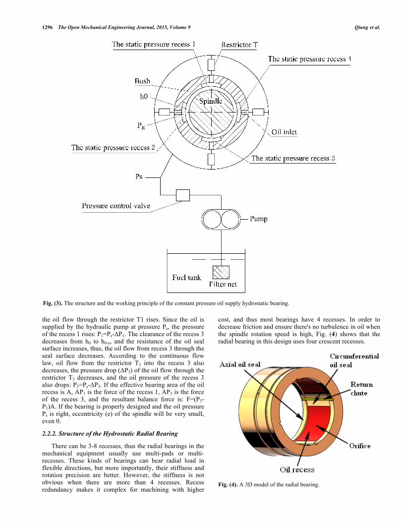
and the structure is complicated. Thus, the design in this paper uses constant pressure oil supply hydrostatic bearing. The structure and the working principle of the constant pressure oil supply hydrostatic bearing are shown in Fig. (3). The hydraulic pump outputs lubricating oil at a certain pressure (Ps), and the oil flows through the restrictor T into the static pressure oil recess. If the gravity acting on the spindle is neglected, the oil pressure (Pr) in all recesses is the same, the spindle will be in the middle of the bearing and the clearance between the spindle and the bearing is the design
clearance (h0). Under these assumptions, whether the spindle rotates or not, the surfaces of the spindle and the bearing are separated and the friction between them is liquid friction. The spindle has an eccentricity (e) when a downward force, including the spindle weight (F), is acting on it. The clearance of the recess 1 increases from h0 to h0+e, and the resistance of the oil seal surface decreases, thus the oil flow through the recess 1 sealing surface increases. According to the continuous flow law, oil flow from the restrictor T1 into the recess 1 also increases, while the pressure drop (ΔP1) of
Fig. (1). Structure of the hydrostatic spindle.
Fig. (2). Structure of the unloading mechanism.
1296 The Open Mechanical Engineering Journal, 2015, Volume 9 Qiang et al.
the oil flow through the restrictor T1 rises. Since the oil is supplied by the hydraulic pump at pressure Ps, the pressure of the recess 1 rises: P1=Ps-ΔP1. The clearance of the recess 3 decreases from h0 to h0-e, and the resistance of the oil seal surface increases, thus, the oil flow from recess 3 through the seal surface decreases. According to the continuous flow law, oil flow from the restrictor T3 into the recess 3 also decreases, the pressure drop (ΔP3) of the oil flow through the restrictor T3 decreases, and the oil pressure of the recess 3 also drops: P3=Ps-ΔP3. If the effective bearing area of the oil recess is A, AP1 is the force of the recess 1, AP3 is the force of the recess 3, and the resultant balance force is: F=(P3-P1)A. If the bearing is properly designed and the oil pressure Ps is right, eccentricity (e) of the spindle will be very small, even 0.
2.2.2. Structure of the Hydrostatic Radial Bearing
There can be 3-8 recesses, thus the radial bearings in the mechanical equipment usually use multi-pads or multi-recesses. These kinds of bearings can bear radial load in flexible directions, but more importantly, their stiffness and rotation precision are better. However, the stiffness is not obvious when there are more than 4 recesses. Recess redundancy makes it complex for machining with higher
cost, and thus most bearings have 4 recesses. In order to decrease friction and ensure there's no turbulence in oil when the spindle rotation speed is high, Fig. (4) shows that the radial bearing in this design uses four crescent recesses.
Fig. (4). A 3D model of the radial bearing.
Fig. (3). The structure and the working principle of the constant pressure oil supply hydrostatic bearing.

Experimental Study of the Hydrostatic Spindle with Orifice Restrictors The Open Mechanical Engineering Journal, 2015, Volume 9 1297
2.2.3. Structure of the Hydrostatic Thrust Bearing
Bi-directional thrust bearing of this spindle unit was positioned in front of the radial bearing. Such design applies to large axial load or high precision equipment in order to limit axial movement. The recess structure of the hydrostatic thrust bearing is divided into a single recess or multiple recesses. A single recess thrust bearing is relatively simple in structure and can be easily machined. Fig. (5) shows the thrust bearing of this spindle.
3. MATHEMATICAL MODEL OF THE HYDROSTATIC BEARING PAD
3.1. Model Assumptions
The following are the basic assumptions and computational conditions: (i) Fluid of the hydrostatic bearing recess is
incompressible, following three-dimensional steady state flow;
(ii) Stiffness of the hydrostatic bearing is infinite, that is, the axial displacement is zero;
(iii) There's no relative sliding between the oil and the bush.
(iv) Inertia of the oil can be neglected and pressure of the oil film border is zero;
(v) Calculated Reynolds number is ≤ 2300, thus there is laminar flow in the recesses, and the laminar flow model is used for analysis of the flow field in the recesses.
(vi) Thermal deformation of the bearing bush and the spindle is ignored.
3.2. Basic Hydromechanics Equations
3.2.1. Conservation of Mass Equation
If three-dimensional elements of the bearing pad are considered, the law of conservation of mass can be expressed as the mass increase of the fluid in the element at a certain
time being equal to the net mass flow into it. It can be expressed as [30]:
( ) 0U n dA dVt
ρ ρ∂⋅ + =∂∫∫ ∫∫∫
(1)
Differentiation yields:
(2)
where ρ is the density, t is the time, u, v and w are components of the velocity vector U in the x, y and z directions. For incompressible fluid, whose density does not change with time, the continuity equation is:
(3)
and
(4)
3.2.2. Conservation of Mechanical Energy
Fig. (6). Branched pipeline.
As shown in Fig. (6), the pipe branch B goes upstream past the point O. The characteristics of the fluid in the branched pipes B and C are defined as in [31]:
( ) ( ) ( ) 0u v w
t x y zρ ρ ρρ ∂ ∂ ∂∂ + + + =
∂ ∂ ∂ ∂
0tρ∂ =∂
( ) ( ) ( ) 0u v wx y z
∂ ∂ ∂+ + =
∂ ∂ ∂
Fig. (5). Structure of the single recess thrust bearing.

1298 The Open Mechanical Engineering Journal, 2015, Volume 9 Qiang et al.
(5)
(6),
then
(7)
At last, the sum of the total mechanical energy and the energy loss is the same per unit mass of the fluid in the two branched pipes. In addition, the flux of the main pipe equals to the sum of the fluxes of the branched pipes:
(8)
3.2.3. Reynolds Equation
According to the Navier-Stokes equations and the engineering practice, the simplified conditions of the hydrostatic bearing flow model are: (i) The oil film in the hydrostatic bearing is relatively
thin compared with its width and length. For the thrust bearing the curvature of the film can be neglected and its rotation speed can be replaced with the translational speed;
(ii) The variation of pressure is ignored along the thickness direction of the oil film;
(iii) The flow state is laminar flow and there're no vortexes and turbulence;
(iv) There's no external force acting on the film; (v) Inertia force of the fluid is relatively small compared
with the viscous shear stress. Inertia force includes the force that accelerates the fluid, the centrifugal force that bends the film, and gravity acting on the fluid;
(vi) There's no sliding on the bearing; (vii) When the load of the incompressible fluid is steady
(density of the fluid is also constant) and the rotating speed of the spindle is r, the Reynolds equation of the thrust bearing and the radial bearing is:
∂∂x
h3
η∂P∂x
⎛⎝⎜
⎞⎠⎟+ ∂∂z
h3
η∂P∂z
⎛⎝⎜
⎞⎠⎟= 6r ∂h
∂x (9)
The process of the oil flow from the pump into the recesses at a certain pressure and eventually out of the bearing clearance may be considered viscous flow. This process obeys the Reynolds equation in the dimensionless form:
(10)
where λ is the length/diameter ratio, λ=D/L, φ is the theta coordinate, p is the pressure of the film, y is the radial coordinate, y , p , h , µ , ω are the non-dimensional radial coordinate, pressure, oil film thickness, viscosity and angular velocity, respectively.
4. NUMERICAL SIMULATION OF THE HYDROSTATIC BEARING
4.1. Numerical Model
ANSYS CFX pre-processing includes meshing the model and setting the boundary conditions. The four recesses of the radial bearing are uniformly distributed in the bearing and their geometry is symmetrical. For the no-loading condition and to reduce the amount of computation, the simplified model only needs to analyze one of the recesses. In this design the bi-directional thrust bearing is also symmetric. Its recesses were designed on the end surface of the thrust bearing and on the bearing cap, so the simplified model considers a single oil pad. The mesh occupies 1/4 of the radial bearing pad and 1/2 of the thrust bearing pad. The mesh was refined at the step of the oil pad and in the area of significant pressure gradient to gain better accuracy and convergence. Fig. (7) shows the mesh of the two models. Then the model was imported into the ANSYS CFX pre-processor to set the boundary conditions. Boundary conditions are listed in Table 1 and Fig. (8) shows the updated model.
4.2. Results
Fig. (9) shows the oil pressure and oil flow velocity of the radial bearing recess at 800 rpm. This analysis didn’t consider the external load. Fig. (9a) shows that the negative pressure around the oil-returning slot is about 0.5 MPa, and the majority the recess pressure is 1 MPa. Fig. (9b) shows that the streamline is dense in the direction of rotation, and the velocity of the oil flow is about 15.5 m/s.
2 2
,2 2bO O bB B
o B f Bu P u Pgz gz h
ρ ρ+ + = + + +∑
2 2
,2 2bO O bC C
o C f Cu P u Pgz gz h
ρ ρ+ + = + + +∑
2 2
, ,2 2bB bC CB
B f B C f Cu u PPgz h gz h
ρ ρ+ + + = + + +∑ ∑
, ,s s A s BV V V= +
3 32 d3
dh p h p h
y yλ µω
ϕ ϕ ϕµ µ
⎛ ⎞ ⎛ ⎞∂ ∂ ∂ ∂⎜ ⎟ ⎜ ⎟+ =⎜ ⎟ ⎜ ⎟∂ ∂ ∂ ∂⎝ ⎠ ⎝ ⎠
Fig. (7). Meshed model of the radial bearing pad and the thrust bearing pad: (a) meshed 1/4 part of the radial bearing pad; (b) meshed 1/2 part of the thrust bearing pad.
(a) (b)

Experimental Study of the Hydrostatic Spindle with Orifice Restrictors The Open Mechanical Engineering Journal, 2015, Volume 9 1299
Fig. (10) presents the oil pressure and flow velocity of the thrust bearing recess under the same conditions as the radial bearing. The negative pressure around the inlet is 29.9
MPa, while the majority of the recess is at 3.8 MPa pressure. The average oil flow velocity is about 0.05 m/s.
Table 1. Boundary conditions of the hydrostatic bearing pad.
Inlet Pressure Oil Temperature Outlet Pressure Rotating Speed Density of Oil Dynamic Viscosity Specific Heat Thermal Conductivity
2.5 MPa 20 °C 0 MPa 800 rpm 860 kg/m3 0.00384 Pa·s 2000 J/kg·K 0.37 W/m·K
Fig. (8). Boundary conditions of the model: (a) radial bearing pad; (b) thrust bearing pad.
Fig. (9). Pressure and streamline distribution of the radial bearing at 800 rpm: (a) pressure distribution; (b) streamline distribution.
(a) (b)
(a)
(b)

1300 The Open Mechanical Engineering Journal, 2015, Volume 9 Qiang et al.
4.3. Rotating Speed Effects on Oil Pressure of the Recess and Oil Flow Velocity
In order to acquire the relationship between the rotating speed, oil pressure of the recess and flow velocity, the boundary conditions were changed to different values, as shown in Fig. (11). Fig. (11a, b) show that the pressure of the recess drops as the rotating speed increases. The negative pressure near the oil return tank in the direction opposite to rotation increases with the spindle rotating speed. The negative pressure of the thrust hydrostatic bearing at the entrance exhibits no obvious increase. Fig. (11c, d) show that the oil flow velocity of the radial bearing rises significantly as the rotating speed of the spindle increases. At some rotation speed, the oil flow velocity of the thrust bearing rises significantly, while at other values it shows the opposite trend. Varying rotating speed has different effects on the different kinds of bearings with constant pressure oil supply.
5. EXPERIMENTAL VERIFICATION OF THE HYDROSTATIC BEARING
5.1. Experimental Setup
Fig. (12) shows the facilities used to test the hydrostatic spindle under no load conditions. The spindle was mounted within the rigid bracket when testing its static characteristics, while its front end was fixed on the bracket. The oil pressure of the inlet is constant and oil pressure of the hydraulic station is 2.5 MPa. The pressure of the radial hydrostatic bearing recess and the auxiliary radial hydrostatic bearing recess is 1.06 MPa and 1.05 MPa, respectively, measured by the pressure gauges. When testing the effect of the rotating speed on the oil pressure of the recess, the spindle is driven by a motor through a belt and its speed is controlled by the frequency converter. The pressure measurements allow testing static characteristics of the spindle. It is currently not possible to test the flow velocity of the oil in the recess and
Fig. (10). Pressure and streamline distribution of the thrust bearing at 800 rpm: (a) pressure distribution; (b) streamline distribution.
(a)
(b)

Experimental Study of the Hydrostatic Spindle with Orifice Restrictors The Open Mechanical Engineering Journal, 2015, Volume 9 1301
Fig. (12). Facilities used for testing the hydrostatic spindle.
directly verify numerical simulation results by experiments. There are no pressure taps in the thrust hydrostatic bearing. However, if the oil pressure calculated numerically and measured experimentally shows good agreement, it can also reflect the influence of the rotating speed on the fluid flow.
5.2. Discussion
Fig. (13) shows that the numerical and experimental results slightly deviate, since the viscosity causes local
Fig. (13). Influence of the spindle rotation speed on the oil pressure of the radial hydrostatic bearing recess under no loading conditions.
pressure loss when the oil flows through the system. Other reasons may be due to slight oil leaks leading to the pressure
0.0 0.2 0.4 0.6 0.8 1.0 1.2
1.040
1.045
1.050
1.055
1.060
1.065
1.070
1.075
Pres
sure
[Mpa
]
Spindle speed[103rmp]
measured simulated
(a) (b)
(c) (d)
Fig. (11). Relations between the hydrostatic bearing recess pressure, oil velocity and the spindle rotation speed: (a) the radial hydrostatic bearing recess pressure and the negative pressure near the oil return tank; (b) the thrust hydrostatic bearing recess pressure and the entrance negative pressure; (c) the radial hydrostatic bearing recess oil velocity and the spindle rotation speed; (d) the thrust hydrostatic bearing recess oil velocity and the spindle rotation speed.
0.0 0.2 0.4 0.6 0.8 1.0 1.21.045
1.050
1.055
1.060
1.065
1.070
1.075
B-p
ress
ure[Mpa
]
Spindle speed[103rpm]
B-Bearing recess
-‐0.52
-‐0.50
-‐0.48
-‐0.46
C-p
ress
ure[Mpa
]
C-Oil return tank negative pressure
0.0 0.2 0.4 0.6 0.8 1.0 1.2
3.80
3.85
3.90
3.95
4.00
4.05
B-p
ress
ure[Mpa
]
Spindle Speed[103rpm]
B-Bearing recess
-‐29.96
-‐29.94
-‐29.92
-‐29.90
-‐29.88
C-p
ress
ure[Mpa
]
C-Thrust bearing entrance
0.0 0.2 0.4 0.6 0.8 1.0 1.215.20
15.25
15.30
15.35
15.40
15.45
15.50
15.55
15.60
Spee
d[m/s
]
Spindle speed[103rpm]
Radial oil velocity
0.0 0.2 0.4 0.6 0.8 1.0 1.22
4
6
8
10
12
14
16
18
20
22
Spee
d[10
-2m/s
]
Spindle speed[103rpm]
Radial oil velocity

1302 The Open Mechanical Engineering Journal, 2015, Volume 9 Qiang et al.
drop and part of the energy being converted to heat, which increases the hydraulic system temperature. Fig. (13) also shows from either numerical or experimental results that the radial hydrostatic oil pressure presents a downward trend with the spindle rotation speed. This is because the centrifugal force drives the oil out of the bearing with the rotation speed increase.
CONCLUSION
The rolling bearing of the original cold drawing spindle has short operating life and suffers from excess vibration and noise. In this paper, a hydrostatic cold drawing spindle with orifice restrictors was designed and the numerical model of the hydrostatic bearing was developed and analyzed, with the numerical results verified experimentally. The conclusions of this study are summarized as follows: (i) The unloading mechanism, two hydrostatic radial
bearings and the thrust bearing were designed, according to the mechanical characteristics of the spindle. The bearing position of the spindle is unchanged when the rolling bearings are replaced by the two hydrostatic radial bearings and the thrust bearing. This arrangement has high axial positioning precision and stability, ensuring the radial and axial stiffness of the spindle.
(ii) Numerical model of the radial bearing and the thrust bearing was developed to study the influence of the rotation speed on the oil pressure of the recess and the oil flow velocity. Numerical results show that the pressure of the recess gently declines as the rotation speed increases, while the negative pressure rises in the area of the thrust bearing inlet and the radial bearing oil return tank, in the opposite direction of the rotation. As the rotation speed increases, the flow velocity of the fluid in the thrust bearing increases. However, in the radial bearings, the fluid flow rate has little correlation with the rotation speed.
(iii) The numerical and experimental results are consistent, showing that this study successfully forecasted the relationship between the rotation speed of the spindle and the oil pressure of the recesses. It also provides data for the follow-up study of the relationship between the oil pressure of the recesses and the deformation of the spindle unit.
CONFLICT OF INTEREST
The authors confirm that this article content has no conflict of interest.
ACKNOWLEDGEMENTS
The project was supported by the National Natural Science Foundation of China (51105002), the National Science and Technology Major Project (2012ZX04005-021), the Natural Science Foundation of the Henan Province (122102210246), and the Foundation of the Henan Educational Committee (13A460002).
REFERENCES
[1] X. feng, J. Yao, and X. Zeng, “Numerical Simulation of Closing Process of Shuttle Check Valve,” The Open Mechanical Engineering Journal, vol. 9, pp. 714-720, 2015.
[2] J. Xu, and S. Zhou, “Analysis of Flow Field for Automotive Exhaust System Based on Computational Fluid Dynamics,” The Open Mechanical Engineering Journal, vol. 8, pp. 587-593, 2014.
[3] G. Zhao, J. Kong, and L. Song, “Research on Flow and Temperature Fields in Aircraft Engines,” The Open Mechanical Engineering Journal, vol. 8, pp. 731-738, 2014.
[4] K. Wang, J. Tang, and G. Li, “Research on Parametric Design of Hydraulic Retarder Based on MultiField Coupling of Heat, Fluid and Solid,” The Open Mechanical Engineering Journal, vol. 9, pp. 58-64, 2015.
[5] Z. Zhang, C. Lin, and W. Ye, “Research on the Flow Characteristics of Sudden-Reduction Oil Tube,” The Open Mechanical Engineering Journal, vol. 9, pp. 77-79, 2015.
[6] M. K. Ghosh, and N. S. Viswanath, “Frequency dependent stiffness and damping coefficients of orifice compensated multi-recess hydrostatic journal bearings,” International Journal of Machine Tools and Manufacture, vol. 27, pp. 275–287, 1987.
[7] Z. Wang, W. Zhao, and Y. Chen, “Prediction of the effect of speed on motion errors in hydrostatic guideways,” International Journal of Machine Tools and Manufacture, vol. 64, pp. 78–84, 2013.
[8] R. S. Dioxon, and R. Leonard, “Formulae defining the performance of hydrostatic journal bearings incorporating 3, 4, 5 and 6 recesses,” Recent International Journal of Machine Tools and Manufacture, vol. 64, pp. 85–94, 1974.
[9] S. C. Sharma, V. Kumar, and S. C. Jain, “A study of slot-entry hydrostatic/hybrid journal bearing using the finite element method,” Tribology International, vol. 32, pp. 185–196, 1999.
[10] S. C. Sharma, V. M. Phalle, and S. C. Jain, “Performance analysis of a multirecess capillary compensated conical hydrostatic journal bearing,” Tribology International, vol. 44, pp. 617–6, 2011.
[11] E. R. Nicodemus, and S. C. Sharma, “Orifice compensated multirecess hydrostatic/hybrid journal bearing system of various geometric shapes of recess operating with micropolar lubricant,” Tribology International, vol. 44, pp. 284–296, 2011.
[12] J. Shao, C. Dai, Y. Zhang, X. Yu, X. Xu, and Y. Wang, “The effect of oil cavity depth on temperature field in heavy hydrostatic thrust bearing,” Journal of Hydrodynamics, vol. 5, no. 23, pp. 670–680, 2011.
[13] Y. Zhang, L. Fan, R. Li, C. Dai, and X. Yu, “Simulation and experimental analysis of supporting characteristics of multiple oil pad hydrostatic bearing disk,” Journal of Hydrodynamics, vol. 2, no. 25, pp. 236–241, 2013.
[14] L. Lu, H. Su, Y. Liang, and Q. Zhang, “Research on static stiffness of hydrostatic bearing using fluid-structure interaction analysis,” Procedia Engineering, vol. 29 pp. 1304–1308, 2012.
[15] J. K. Martin, “Measured stiffness and displacement coefficients of a stationary rotor hydrostatic bearing,” Tribology International, vol. 37, pp. 809–816, 2004.
[16] W. Chen, Y. Sun, Y. Liang, Q. Bai, P. Zhang, and H. Liu, “Hydrostatic spindle dynamic design system and its verification,” Proceedings of the Institution of Mechanical Engineers, Part B: Journal of Engineering Manufacture vol. 228, no. 1, pp. 149–155, 2014.
[17] S. Uberti, G. Baronio, and D. Cambiaghi, “Study & design of a special test bench for hydrostatic spindle housings,” Proceedings of DESIGN 2010, the 11th International Design Conference, Dubrovnik, Croatia, pp. 1729–1740, 2010.
[18] P. Liang, C. Lu, W. Pan, “A new method for calculating the static performance of hydrostatic journal bearing,” Tribology International, vol. 77, pp. 72–77, 2014.
[19] T. A. Osman, M. Dorid, and Z. S. Safar, “Experimental assessment of hydrostatic thrust bearing performance,” Tribology International, vol. 3, no. 29, 233–239, 1996.
[20] M. Gohara, K. Somaya, and S. Yoshimoto, “Static characteristics of a water-lubricated hydrostatic thrust bearing using a membrane restrictor,” Tribology International, vol. 75, pp. 111–116, 2014.
[21] S. K. Yadav, and S. C. Sharma, “Performance of hydrostatic tilted thrust pad bearings of various recess shapes operating with non-Newtonian lubricant,” Finite Elements in Analysis and Design, vol. 87, pp. 43–55, 2014.

Experimental Study of the Hydrostatic Spindle with Orifice Restrictors The Open Mechanical Engineering Journal, 2015, Volume 9 1303
[22] D. V. De Pellegrin, and D. J. Hargreaves, “An isoviscous, isothermal model investigating the influence of hydrostatic recesses on a spring-supported tilting pad thrust bearing,” Tribology International, vol. 51, pp. 25–35, 2012.
[23] S. C. Sharma, S. C. Jain, and D. K. Bharuka, “Influence of recess shape on the performance of a capillary compensated circular thrust pad hydrostatic bearing,” Tribology International, vol. 35, pp. 347–356, 2002.
[24] U. P. Singh, R. S. Gupta, and V. K. Kapur, “On the application of Rabinowitsch fluid model on an annular ring hydrostatic thrust bearing,” Tribology International, vol. 58, pp. 65–70, 2013.
[25] J. R. Lin, “Surface roughness effect on the dynamic stiffness and damping characteristics of compensated hydrostatic thrust bearings,” International Journal of Machine Tools and Manufacture, vol. 40, pp. 1671–1689, 2000.
[26] T. A. Osman, Z. S. Satar, and M. O. A. Mokhtar, “Design of annular recess hydrostatic thrust bearing under dynamic loading,” Tribology International, vol. 24, no. 3, pp. 137–141, 1991.
[27] U. Nishio, K. Somaya, and S. Yoshimoto, “Numerical calculation and experimental verification of static and dynamic characteristics of aerostatic thrust bearings with small feedholes,” Tribology International, vol. 44, pp. 1790–1795, 2011.
[28] A. W. Yacout, A. S. Ismaeel, and S. Z. Kassab, “The combined effects of the centripetal inertia and the surface roughness on the hydrostatic thrust spherical bearings performance,” Tribology International, vol. 40, pp. 522–532, 2007.
[29] D. Chen, J. Fan, and F. Zhang, “Dynamic and static characteristics of a hydrostatic spindle for machine tools,” Journal of Manufacturing Systems, vol. 31, pp. 33, 2012.
[30] E. Su, “Tube dynamic analysis and numerical calculation method for fluid flow,” Harbin institute of technology press, Harbin, 1985.
[31] Z. Wang, “Fundamental theory for hydromechanics,” Higher education press, Beijing, 1987.
Received: March 10, 2015 Revised: October 16, 2015 Accepted: October 19, 2015 © Qiang et al.; Licensee Bentham Open.
This is an open access article licensed under the terms of the (https://creativecommons.org/licenses/by/4.0/legalcode ), which permits unrestricted, non-commercial use, distribution and reproduction in any medium, provided the work is properly cited.