NUMERICAL PREDICTION OF DEFORMATIONS IN ...Numerical subroutine DFLUX is implemented into Abaqus FEA...
8
1. Introduction Deformations of welded construction that occur during welding are one of the major problems of this material joining technology. The main cause of their formation is uneven expansion and contraction of the weld during the heating and cooling processes. The character and size of deformations depends on the physical properties of the base material, rigidity of a construction and the welding method. The proper selection of the welding technology and technological parameters of the process can reduce deformations in a large extent [1-4]. In the laser beam welding process, using high welding speeds, a good quality welds are obtained with a narrow thermal influence zone, which is helpful in reducing the deformation of the workpiece and helpful in increasing quality and efficiency of the production [5, 6]. This is particularly important in welding of long parts in a large structure. Unquestionable advantages of laser welding contribute to the very intense development of this welding technique and wider application in various industries [7, 8]. A quantitative analysis and control of occurring deformations in welded joint for assumed various process parameters is important in the theory and engineering applications of welding processes [9]. This is particularly important in the case of large-scale welded structures where operations of the deformation reduction are practically impossible [10]. A significant technological problem is the determination of the stress and strain generated at the interface of joined elements and adjacent zones [5, 7, 11]. The full control of arising deformations is very difficult due A R C H I V E S O F M E T A L L U R G Y A N D M A T E R I A L S Volume 60 2015 Issue 3 DOI: 10.1515/amm-2015-0334 W. PIEKARSKA* ,# , M. KUBIAK*, Z. SATERNUS*, S. STANO**, T. DOMAŃSKI* NUMERICAL PREDICTION OF DEFORMATIONS IN LASER WELDED SHEETS MADE OF X5CrNi18-10 STEEL PROGNOZOWANIE NUMERYCZNE ODKSZTAŁCEŃ PŁASKOWNIKÓW ZE STALI X5CrNi18-10 SPAWANYCH LASEROWO The work concerns the numerical modelling of coupled thermal and mechanical phenomena occurring in the laser beam welding process. Commercial Abaqus FEA engineering software is adopted to numerical computations in order to perform a comprehensive analysis of thermo-mechanical phenomena. Created in Fortran programming language additional numerical subroutines are implemented into Abaqus solver, used to describe the power intensity distribution of the movable laser beam heat source. Temperature dependent thermomechanical properties of X5CrNi18-10 steel are adopted in the numerical analysis of stress and strain states. Mathematical and numerical models are verified on the basis of a comparison between selected results of computer simulations and experimental studies on butt-welded joints. Numerical simulations are presented for steel sheet with a thickness of 2 mm. Temperature distributions, the shape and size of melted zone as well as residual stress and deformations are presented for analyzed elements. Numerically determined deflections are compared with the measured deflection of welded joint. Keywords: Laser welding, numerical modelling, ABAQUS, deformations, stainless steel Praca dotyczy modelowania numerycznego sprzężonych zjawisk cieplnych i mechanicznych występujących w procesie spawania z zastosowaniem wiązki promieniowania laserowego. W celu przeprowadzenia kompleksowej analizy zjawisk termomechanicznych zaadaptowano do obliczeń numerycznych komercyjny pakiet oprogramowania inżynierskiego Abaqus FEA. W programie zaimplementowano dodatkową procedurę numeryczną utworzoną w języku programowania Fortran, służącą do opisu rozkładu intensywności mocy ruchomego źródła ciepła wiązki laserowej. W prognozowaniu numerycznym naprężeń i odkształceń uwzględniono zależne od temperatury własności termomechaniczne dla przyjętej w obliczeniach stali X5CrNi18-10. Weryfikacje modeli matematycznych i numerycznych przeprowadzono w oparciu o porównanie wybranych wyników symulacji komputerowej z badaniami doświadczalnymi połączeń spawanych doczołowo. Symulacje numeryczne spawania laserowego przedstawiono dla płaskownika o grubości 2 mm. Wyznaczono rozkłady temperatury, określono kształt i wielkość strefy przetopienia złącza spawanego oraz naprężenia własne i deformacje. Wyznaczone numerycznie ugięcia porównano z wynikami pomiarów ugięć połączenia spawanego. * CZESTOChOWA UNIvERSITy OF TEChNOlOgy, INSTITUTE OF MEChANICS AND MAChINE DESIgN FOUNDATIONS, 73 DąBROWSKI STR., 42-200 CZęSTOChOWA, POlAND ** WElDINg INSTITUTE, 16-18 BłOgOSłAWIONEgO CZESłAWA STR., 44-100 glIWICE, POlAND # Corresponding author: [email protected]
Transcript of NUMERICAL PREDICTION OF DEFORMATIONS IN ...Numerical subroutine DFLUX is implemented into Abaqus FEA...

1. Introduction
Deformations of welded construction that occur during welding are one of the major problems of this material joining technology. The main cause of their formation is uneven expansion and contraction of the weld during the heating and cooling processes. The character and size of deformations depends on the physical properties of the base material, rigidity of a construction and the welding method. The proper selection of the welding technology and technological parameters of the process can reduce deformations in a large extent [1-4].
In the laser beam welding process, using high welding speeds, a good quality welds are obtained with a narrow thermal influence zone, which is helpful in reducing the deformation of the workpiece and helpful in increasing quality and efficiency
of the production [5, 6]. This is particularly important in welding of long parts in a large structure. Unquestionable advantages of laser welding contribute to the very intense development of this welding technique and wider application in various industries [7, 8].
A quantitative analysis and control of occurring deformations in welded joint for assumed various process parameters is important in the theory and engineering applications of welding processes [9]. This is particularly important in the case of large-scale welded structures where operations of the deformation reduction are practically impossible [10]. A significant technological problem is the determination of the stress and strain generated at the interface of joined elements and adjacent zones [5, 7, 11]. The full control of arising deformations is very difficult due
A R C H I V E S O F M E T A L L U R G Y A N D M A T E R I A L S
Volume 60 2015 Issue 3DOI: 10.1515/amm-2015-0334
W. PIEKARSKA*,#, M. KUBIAK*, Z. SATERNUS*, S. STANO**, T. DOMAŃSKI*
NUMERICAL PREDICTION OF DEFORMATIONS IN LASER WELDED SHEETS MADE OF X5CrNi18-10 STEEL
PROGNOZOWANIE NUMERYCZNE ODKSZTAŁCEŃ PŁASKOWNIKÓW ZE STALI X5CrNi18-10 SPAWANYCH LASEROWO
The work concerns the numerical modelling of coupled thermal and mechanical phenomena occurring in the laser beam welding process. Commercial Abaqus FEA engineering software is adopted to numerical computations in order to perform a comprehensive analysis of thermo-mechanical phenomena. Created in Fortran programming language additional numerical subroutines are implemented into Abaqus solver, used to describe the power intensity distribution of the movable laser beam heat source. Temperature dependent thermomechanical properties of X5CrNi18-10 steel are adopted in the numerical analysis of stress and strain states. Mathematical and numerical models are verified on the basis of a comparison between selected results of computer simulations and experimental studies on butt-welded joints.
Numerical simulations are presented for steel sheet with a thickness of 2 mm. Temperature distributions, the shape and size of melted zone as well as residual stress and deformations are presented for analyzed elements. Numerically determined deflections are compared with the measured deflection of welded joint.
Keywords: Laser welding, numerical modelling, ABAQUS, deformations, stainless steel
Praca dotyczy modelowania numerycznego sprzężonych zjawisk cieplnych i mechanicznych występujących w procesie spawania z zastosowaniem wiązki promieniowania laserowego. W celu przeprowadzenia kompleksowej analizy zjawisk termomechanicznych zaadaptowano do obliczeń numerycznych komercyjny pakiet oprogramowania inżynierskiego Abaqus FEA. W programie zaimplementowano dodatkową procedurę numeryczną utworzoną w języku programowania Fortran, służącą do opisu rozkładu intensywności mocy ruchomego źródła ciepła wiązki laserowej. W prognozowaniu numerycznym naprężeń i odkształceń uwzględniono zależne od temperatury własności termomechaniczne dla przyjętej w obliczeniach stali X5CrNi18-10. Weryfikacje modeli matematycznych i numerycznych przeprowadzono w oparciu o porównanie wybranych wyników symulacji komputerowej z badaniami doświadczalnymi połączeń spawanych doczołowo.
Symulacje numeryczne spawania laserowego przedstawiono dla płaskownika o grubości 2 mm. Wyznaczono rozkłady temperatury, określono kształt i wielkość strefy przetopienia złącza spawanego oraz naprężenia własne i deformacje. Wyznaczone numerycznie ugięcia porównano z wynikami pomiarów ugięć połączenia spawanego.
* CZESTOChOWA UNIvERSITy OF TEChNOlOgy, INSTITUTE OF MEChANICS AND MAChINE DESIgN FOUNDATIONS, 73 DąBROWSKI STR., 42-200 CZęSTOChOWA, POlAND
** WElDINg INSTITUTE, 16-18 BłOgOSłAWIONEgO CZESłAWA STR., 44-100 glIWICE, POlAND# Corresponding author: [email protected]

1966
to the impact of design and technological factors. Therefore, welding deformations must be analyzed and prevented when it is possible at the stage of construction design. At the time the numerical prediction of deformations in welded joints becomes a helpful tool [3, 7, 12-14].
This paper covers the numerical analysis of laser butt-welding process of austenitic stainless steel sheets made of X5CrNi18-10. The analysis is performed using finite element method (FEM) in Abaqus FEA engineering software. Three dimensional discrete model is created with thermomechanical properties changing with temperature taken into account. Additional numerical subroutine DFLUX, written in Fortran programming language, is implemented into Abaqus FEA solver. The implementation of this subroutine enabled the modeling of movable heat source, where the description of the heat source power distribution is assumed as a Gaussian volumetric heat source power distribution. Temperature field is estimated. The shape and size of melted zone is predicted as well as residual stress and deformations in welded joint. Numerically determined deflection is compared with results of deflection measurements made in a real welded joint.
2. Experiment
The real butt-welding of steel sheets with dimensions 150 x 45 x 2 mm (Fig. 1) is performed in order to select the appropriate welding parameters and to verify numerical models. Butt-welded joints made of austenitic steel X5CrNi18-10 with chemical composition: 0,06 C, 17-19 Cr, 11-13 Ni, N<0,11 [%] are executed at Welding Institute in Gliwice using TruDisk 12002 disk laser made by Trumpf. Welding process is performed without additional material, using argon as a shielding gas from the face of the weld. The following process parameters are used during the experiment: laser beam power QL =3000 W, welding speed v=5.2 m/min, beam radius 0,3 mm and shielding gas flow rate 16 l/min.
Fig. 1. Butt-welded joint: a) the face of the weld, b) cross section, c) the ridge of the weld
The displacement in laser butt-welded joint was measured using laboratory New Form Talysurf profilographometer 2D/3D Taylor Hobson 120 with „Ultra Surface 5.16” and „TalyMap Platinium 5.1.1” software (Fig. 2).
Displacement measurement is carried out on the outer surface of welded joint, along lines 1, 2 and 3. The scheme of lines of the measurement is shown in Fig. 3, where L= 150 mm, b= 90 mm, g= 2 mm.
Fig. 2. Displacement measuring apparatus
Fig. 3. Scheme of lines of the measurement
3. Mathematical model
The analysis of thermal phenomena is made on the basis of the energy conservation equation and Fourier law. The variational formulation of energy conservation equation is expressed in the following form [15]:
(1)
where = (T) is the thermal conductivity [W/(m oC)], U = U(T) is a internal energy[J/kg], qv is laser beam heat source [W/m3], qS is a boundary heat flux [W/m2], δT is a variational function, is a density [kg/m3], T = T(xα,t) is temperature [oC].Equation (1) is completed by the initial condition t = 0 : T = To and boundary conditions of Dirichlet and Neumann type:
(2)
as well as Newton type condition with the heat loss due to convection and radiation [16]:
(3)
additionally, evaporation and heat flux toward welded element are taken into account within the area of heat source activity [17]:
(4)
1967
where k is convective coefficient (assumed as k=150 W/ (m2 oC), is radiation coefficient ( =0.5), is Stefan-Boltzmann constant and q(r,0) is the heat flux towards the top surface of welded workpiece (z=0) in the source activity zone of radius r, T0 is an ambient temperature (assumed as 20oC).
The distribution of welding heat source power is adopted in mathematical model as a movable, volumetric heat source, having Gaussian power distribution with the linear decrease of energy intensity along material penetration depth [18]:
(5)
where QL is a laser beam power [W], h is the heat source penetration depth [m], z is actual depth [m], r0 is a beam radius
[m], is actual radius [m].Solid - liquid phase transformations are taken into account
in the mathematical model of thermal phenomena [7, 19, 20], assuming solidus temperature TS=1400oC, liquidus TL=1455oC and latent heat of fusion HL=260×103 J/kg.
Mechanical analysis in elastic-plastic range is based on classic equilibrium equations, supplemented by constitutive relations as well as initial and boundary conditions, which are assumed to ensure the external static determination of considered system [21]:
(6)
(7)
(8)
where σ=σ(σij) is stress tensor, xα describes location of considered point (material particle), ( ) is inner exhaustive product, D=D(T) is a tensor of temperature dependent material properties.
The total strain is defined as a sum of elastic εe, plastic εp and thermal εTh strains:
(1)
Elastic strain is modelled using an isotropic Hooke’s law, whereas plastic strain is calculated using plastic flow model obeying Huber-Misses plasticity condition [22].
4. Numerical Modelling
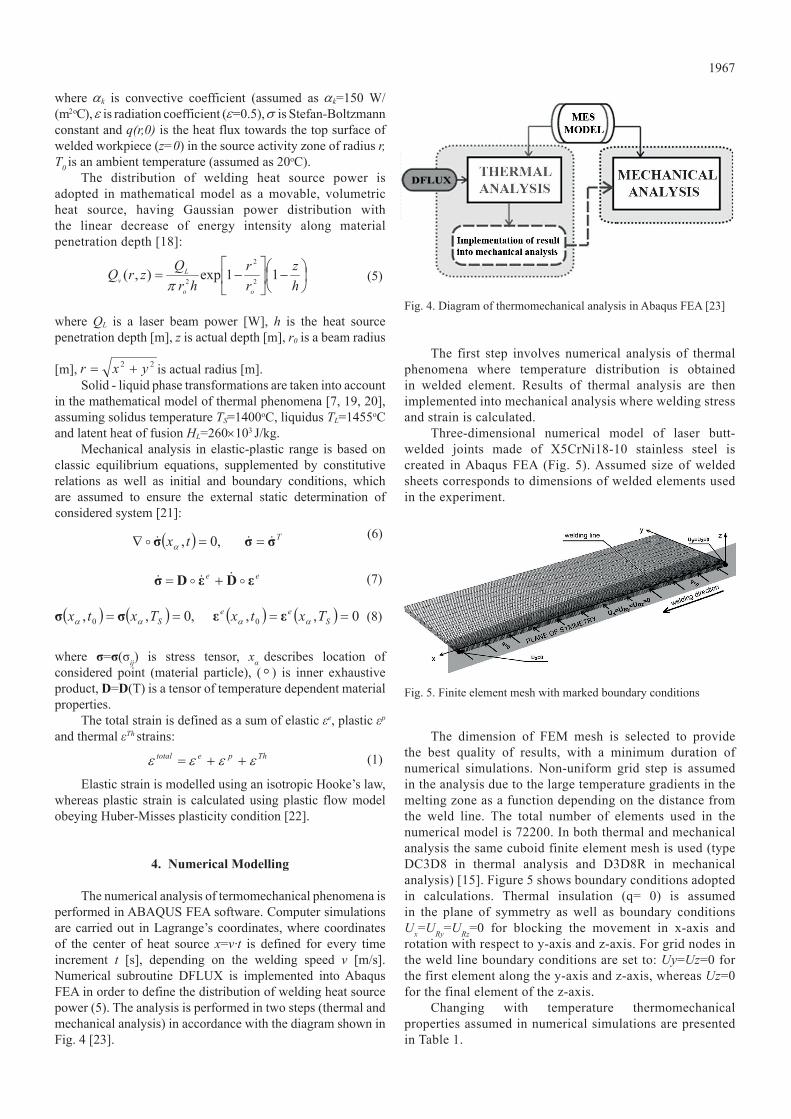
The numerical analysis of termomechanical phenomena is performed in ABAQUS FEA software. Computer simulations are carried out in Lagrange’s coordinates, where coordinates of the center of heat source x=v∙t is defined for every time increment t [s], depending on the welding speed v [m/s]. Numerical subroutine DFLUX is implemented into Abaqus FEA in order to define the distribution of welding heat source power (5). The analysis is performed in two steps (thermal and mechanical analysis) in accordance with the diagram shown in Fig. 4 [23].
Fig. 4. Diagram of thermomechanical analysis in Abaqus FEA [23]
The first step involves numerical analysis of thermal phenomena where temperature distribution is obtained in welded element. Results of thermal analysis are then implemented into mechanical analysis where welding stress and strain is calculated.
Three-dimensional numerical model of laser butt-welded joints made of X5CrNi18-10 stainless steel is created in Abaqus FEA (Fig. 5). Assumed size of welded sheets corresponds to dimensions of welded elements used in the experiment.
Fig. 5. Finite element mesh with marked boundary conditions
The dimension of FEM mesh is selected to provide the best quality of results, with a minimum duration of numerical simulations. Non-uniform grid step is assumed in the analysis due to the large temperature gradients in the melting zone as a function depending on the distance from the weld line. The total number of elements used in the numerical model is 72200. In both thermal and mechanical analysis the same cuboid finite element mesh is used (type DC3D8 in thermal analysis and D3D8R in mechanical analysis) [15]. Figure 5 shows boundary conditions adopted in calculations. Thermal insulation (q= 0) is assumed in the plane of symmetry as well as boundary conditions Ux=URy=URz=0 for blocking the movement in x-axis and rotation with respect to y-axis and z-axis. For grid nodes in the weld line boundary conditions are set to: Uy=Uz=0 for the first element along the y-axis and z-axis, whereas Uz=0 for the final element of the z-axis.
Changing with temperature thermomechanical properties assumed in numerical simulations are presented in Table 1.
1968
5. Results and discussion
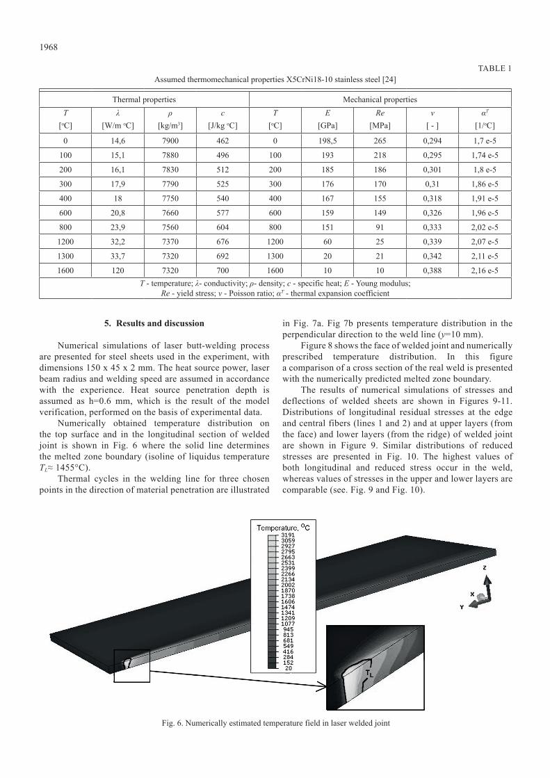
Numerical simulations of laser butt-welding process are presented for steel sheets used in the experiment, with dimensions 150 x 45 x 2 mm. The heat source power, laser beam radius and welding speed are assumed in accordance with the experience. Heat source penetration depth is assumed as h=0.6 mm, which is the result of the model verification, performed on the basis of experimental data.
Numerically obtained temperature distribution on the top surface and in the longitudinal section of welded joint is shown in Fig. 6 where the solid line determines the melted zone boundary (isoline of liquidus temperature TL≈ 1455°C).
Thermal cycles in the welding line for three chosen points in the direction of material penetration are illustrated
in Fig. 7a. Fig 7b presents temperature distribution in the perpendicular direction to the weld line (y=10 mm).
Figure 8 shows the face of welded joint and numerically prescribed temperature distribution. In this figure a comparison of a cross section of the real weld is presented with the numerically predicted melted zone boundary.
The results of numerical simulations of stresses and deflections of welded sheets are shown in Figures 9-11. Distributions of longitudinal residual stresses at the edge and central fibers (lines 1 and 2) and at upper layers (from the face) and lower layers (from the ridge) of welded joint are shown in Figure 9. Similar distributions of reduced stresses are presented in Fig. 10. The highest values of both longitudinal and reduced stress occur in the weld, whereas values of stresses in the upper and lower layers are comparable (see. Fig. 9 and Fig. 10).
TABLE 1Assumed thermomechanical properties X5CrNi18-10 stainless steel [24]
Thermal properties Mechanical propertiesT
[oC]λ
[W/m oC]ρ
[kg/m3]c
[J/kg oC]T
[oC]E
[GPa]Re
[MPa]ν
[ - ]αT
[1/oC]
0 14,6 7900 462 0 198,5 265 0,294 1,7 e-5
100 15,1 7880 496 100 193 218 0,295 1,74 e-5
200 16,1 7830 512 200 185 186 0,301 1,8 e-5
300 17,9 7790 525 300 176 170 0,31 1,86 e-5
400 18 7750 540 400 167 155 0,318 1,91 e-5
600 20,8 7660 577 600 159 149 0,326 1,96 e-5
800 23,9 7560 604 800 151 91 0,333 2,02 e-5
1200 32,2 7370 676 1200 60 25 0,339 2,07 e-5
1300 33,7 7320 692 1300 20 21 0,342 2,11 e-5
1600 120 7320 700 1600 10 10 0,388 2,16 e-5T - temperature; λ- conductivity; ρ- density; c - specific heat; E - Young modulus;
Re - yield stress; ν - Poisson ratio; αT - thermal expansion coefficient
Fig. 6. Numerically estimated temperature field in laser welded joint

1969
Fig. 7. Temperature distribution a) at a various depth of material penetration in the welding line and b) in the perpendicular direction to the weld line
Fig. 8. Laser butt-welded joint with numerically estimated temperature distribution
Fig. 9. longitudinal residual stress σy

1970
Figure 11 shows numerically obtained deflection UZ of welded joint along z-direction in the cross-section. Displacements are presented at the top surface along measuring lines 1, 2 and 3 respectively (Fig. 3). Figure 12 presents a comparison of numerically estimates deflection UZ with displacements obtained in the measurement.
Fig. 11. Numerically estimated deflection UZ in laser welded joint
Steel sheets deformed in transverse and longitudinal directions from the weld line. This is indicated by both numerical analysis and experimental research (see. Fig. 11 and 12). The dominant deflection occurs in the perpendicular direction to welding axis. Deflections in the longitudinal direction slightly increase along the weld line (Fig. 11). The good accuracy of numerically predicted and measured deflections (Fig. 12) indicates the correctness of adapted mathematical and numerical models and the correctness of
selected methodology of numerical simulations.
6. Conclusions
Numerical analysis of thermal and mechanical phenomena in welding processes using Abaqus FEA software requires implementation of additional numerical subroutines written in Fortran programming language. Application of DFLUX subroutine allows the modeling of movable welding source. Experimental studies provided necessary data to determine the heat source penetration depth and were used to verify the numerical model of laser beam heat source power intensity distribution, which provided the proper temperature distribution and appropriate analysis of welding stress and joints deformation. The comparison between the cross section of the weld and numerically obtained shape of melted zone (Fig. 8) as well as obtained good agreement between calculated deflections and measured deflections indicates the correctness of developed mathematical and numerical models of thermal and mechanical phenomena in the laser beam welding process.
Analysis of obtained results of simulations of stress states in welded sheets shows that the highest value of stress (~250MPa) occur in the weld (see. Fig. 9 and Fig. 10). Laser welded joint is deformed in the transverse and longitudinal directions to the weld line, as confirmed by numerical analysis and experimental research. This is also confirmed by stress distributions. Deformations are small, the highest value of deflection of welded sheets is below 250 μm. Numerical estimation of welding deformations in terms of different process parameters may be useful for selecting appropriate parameters that allow to obtain the proper geometry, quality and mechanical properties the designed joint.
Presented models of the analysis of thermomechanical phenomena in Abaqus FEA software, allows for the comprehensive analysis of welding process. Developed numerical models can be used in the evaluation of the quality of welded joints in terms of different process parameters.
Fig. 10. Reduced stress σ

1971
REFERENCES
[1] D. Deng, H. Murakawa, Comp Mater Sci. 43, 353 (2008).[2] H. Long, D. Gery, A. Carlier, P.G. Maropoulos, Mater Design.
30, 4126 (2009).[3] D. Deng, Mater Design. 30, 359 (2009).[4] D. Gery, H. Long, P. Maropoulos, J Mater Process Tech. 167,
393 (2005).[5] J. Pilarczyk, M. Banasik, J. Stano, Przeglad Spawalnictwa.
5-6, 6 (2006).[6] M. Węglowski, S. Stano et al., Mater Sci Forum. 638-642,
3739 (2010).[7] W. Piekarska, Numerical analysis of thermomechanical
phenomena during laser welding process. The temperature fields, phase transformation and stresses, Wydawnictwo Politechniki Częstochowskiej (2007).
[8] A. Bokota, W. Piekarska, Paton Weld J. 6, 19 (2008).[9] P. lacki, Z. Kucharczyk, R.E. Śliwa, T. gałaczyński, Arch
Metall Mater. 58, 597 (2013).[10] W. Piekarska, M. Kubiak, Z. Saternus, Arch Metall Mater. 58,
1391 (2013).[11] Z. Moumni, F. Roger, N. Thuy Trinh, Int J Plasticity. 27, 414
(2011).[12] L. Tian, Y. Luo, Y. Wang, X. Wu, Mater Design. 54, 458 (2014).[13] X. Shan, C.M. Davies, T. Wangsdan, N.P. O`Dowd, K.M.
Nikbin, Int J Pres Ves Pip. 86, 110 (2009).[14] A. Anca, A. Cardona, J. Risso, et al., Appl Math Model. 35,
688 (2011).[15] Abaqus theory manual, Version 6.7, SIMULIA Dassault
System (2007).[16] Z. Malinowski, T. Telejko, B. hadała, Arch Metall Mater. 57,
325 (2012).
Fig. 12. Deflection UZ in laser butt-welded joint for: a) y=10mm, b) y=75 mm, c) y=140 mm

[17] L. Sowa, A. Bokota; Archives of foundry engineering. 11, 139 (2011).
[18] S.A. Tsirkas, P. Papanikos, Th. Kermanidis, J Mater Process Tech. 134, 59 (2003).
[19] L. Sowa, Archives of foundry engineering. 14, 103 (2014).[20] T. Skrzypczak, E. Węgrzyn-Skrzypczak, Int J heat Mass Tran.
55, 4276 (2012).[21] A. Bokota, T. Domański, Arch Metall Mater. 52, 277 (2007).[22] A. Bokota, T. Domański, Arch Metall Mater. 54, 575 (2009).[23] W. Piekarska, M. Kubiak, Z. Saternus, K. Rek, Arch Metall
Mater. 58, 1237 (2013).[24] D. Deng, H. Murakawa, Comp Mater Sci. 37, 269 (2006).
Received: 20 January 2015.