Numerical Modeling of Seismic-induced Soil Response Around Submarine … … · ·...
9
Send Orders of Reprints at [email protected] 98 The Open Civil Engineering Journal, 2012, 6, 98-106 1874-1495/12 2012 Bentham Open Open Access Numerical Modeling of Seismic-induced Soil Response Around Submarine Pipeline X.L. Zhang 1,* and D.S. Jeng 2 1 The Key Laboratory of Urban Security and Disaster Engineering of Ministry of Education, Beijing University of Tech- nology, Beijing 100124, China 2 Division of Civil Engineering, University of Dundee, Dundee, DD1 4HN, UK Abstract: Seismic-induced pore pressure and effective stresses in the saturated porous seabed under seismic loading are the main factors that govern the overall stability of submarine pipelines. In most of the previous investigations for the seismic-induced dynamic response around a submarine pipeline have been limited to two-dimension cases. In this paper, a three-dimensional finite element model including buried pipeline is established by extending DYNE3WAC. Based on the numerical model presented, the effects of pipeline geometry and soil characteristics on the seismic-induced pore pressure of the seabed and internal stresses of submarine pipeline will be discussed in detail. Keywords: Submarine pipeline, dynamic response, excess pore pressure, internal stresses, seismic loading. 1. INTRODUCTION It has been widely reported in the literature that earth- quakes have damaged many lifeline structures, such as sub- way, tunnels and buried pipeline, which may further cause fires, gas leaking and economic losses [1]. The submarine pipelines in earthquake active areas are subjected to both wave and seismic loading during earthquakes. It is more complex and important to analyze the dynamic response of submarine pipeline for the reliable design of pipeline. Subsequently, the seismic analysis and behavior of bur- ied pipelines have been investigated by many researchers. Various approaches for the seismic-induced seabed response have been carried out since the 1970’s. Among these, regard- ing analytical approximations, the simplest analytical model- ing of a buried pipeline was proposed by Newmark [2] and Hall [3]. In their models, the pipeline is assumed to follow the deformation of the ground, but processes of the soil- pipeline interactions were not considered. The experimental studies mainly include forced vibration tests, earthquake simulator tests and centrifugal shaking table tests [4]. Com- paratively, centrifugal modeling could capture the real stress field of the soil and produce more authentic and reliable re- sults [5]. Wong et al. [6] demonstrated the importance of considering the effect of pipeline motion in modifying the free field ground motion into the pipeline analysis using the FEM (finite element method) method. Zou et al. [7] con- ducted the shaking table model test on pipelines buried in saturated sand foundation, also used numerical model to simulate the process of build-up and dissipation of *Address correspondence to this author at the The Key Laboratory of Urban Security and Disaster Engineering of Ministry of Education, Beijing Univer- sity of Technology, Beijing 100124, China, Tel.: +86(15210581913); Fax: +86-10-67392461; E-mail: [email protected] pore pressure in foundation around the pipelines and com- pared it with shaking table test results. To the authors’ best knowledge, the majority of previous research of numerical models about submarine pipeline has been limited to two-dimension cases, although earthquakes may happen in mixed directions in the real environment. Therefore, it is necessary to develop a three-dimensional model to investigate these realistic circumstances. To simu- late the dynamic response of three-dimensional model under seismic loading, a finite element program, DYNE3WAC (DYNamic Earthquake Analysis Program 3D Window Ver- sion for ACademic) developed by Ou [8], is used. The model is based on the fully implicit u-p approximation of the Biot formulation [9]. The program can be used for static, consoli- dation and dynamic situations under drained and un-drained conditions. In this paper, the 3D finite element model (DYNE- 3WAC) will be further enhanced by including buried pipe- line in the model. Based on the numerical model, a paramet- ric study is conducted to examine the effects of pipeline ge- ometry and soil characteristics on the seismic-induced pore pressure of the seabed and internal stresses of submarine pipeline will be discussed in detail. 2. BOUNDARY VALUE PROBLEM In this study, a three-dimensional problem is considered. A fully buried pipeline (with a radius 0.5D) is located in a porous seabed of finite thickness h laid upon an impermeable rigid bottom and surrounding by four impermeable walls see Fig. (1). The z-direction is measured positive upward from the surface of seabed, and y-direction is the horizontal which is perpendicular in direction to the axes of pipeline. The mesh of total three-dimensional model is depicted in Fig. (2).
-
Upload
nguyenkhue -
Category
Documents
-
view
213 -
download
0
Transcript of Numerical Modeling of Seismic-induced Soil Response Around Submarine … … · ·...

Send Orders of Reprints at [email protected]
98 The Open Civil Engineering Journal, 2012, 6, 98-106
1874-1495/12 2012 Bentham Open
Open Access
Numerical Modeling of Seismic-induced Soil Response Around Submarine Pipeline
X.L. Zhang1,* and D.S. Jeng2
1The Key Laboratory of Urban Security and Disaster Engineering of Ministry of Education, Beijing University of Tech-nology, Beijing 100124, China 2Division of Civil Engineering, University of Dundee, Dundee, DD1 4HN, UK
Abstract: Seismic-induced pore pressure and effective stresses in the saturated porous seabed under seismic loading are the main factors that govern the overall stability of submarine pipelines. In most of the previous investigations for the seismic-induced dynamic response around a submarine pipeline have been limited to two-dimension cases. In this paper, a three-dimensional finite element model including buried pipeline is established by extending DYNE3WAC. Based on the numerical model presented, the effects of pipeline geometry and soil characteristics on the seismic-induced pore pressure of the seabed and internal stresses of submarine pipeline will be discussed in detail.
Keywords: Submarine pipeline, dynamic response, excess pore pressure, internal stresses, seismic loading.
1. INTRODUCTION
It has been widely reported in the literature that earth-quakes have damaged many lifeline structures, such as sub-way, tunnels and buried pipeline, which may further cause fires, gas leaking and economic losses [1]. The submarine pipelines in earthquake active areas are subjected to both wave and seismic loading during earthquakes. It is more complex and important to analyze the dynamic response of submarine pipeline for the reliable design of pipeline.
Subsequently, the seismic analysis and behavior of bur-ied pipelines have been investigated by many researchers. Various approaches for the seismic-induced seabed response have been carried out since the 1970’s. Among these, regard-ing analytical approximations, the simplest analytical model-ing of a buried pipeline was proposed by Newmark [2] and Hall [3]. In their models, the pipeline is assumed to follow the deformation of the ground, but processes of the soil-pipeline interactions were not considered. The experimental studies mainly include forced vibration tests, earthquake simulator tests and centrifugal shaking table tests [4]. Com-paratively, centrifugal modeling could capture the real stress field of the soil and produce more authentic and reliable re-sults [5]. Wong et al. [6] demonstrated the importance of considering the effect of pipeline motion in modifying the free field ground motion into the pipeline analysis using the FEM (finite element method) method. Zou et al. [7] con-ducted the shaking table model test on pipelines buried in saturated sand foundation, also used numerical model to simulate the process of build-up and dissipation of
*Address correspondence to this author at the The Key Laboratory of Urban Security and Disaster Engineering of Ministry of Education, Beijing Univer-sity of Technology, Beijing 100124, China, Tel.: +86(15210581913); Fax: +86-10-67392461; E-mail: [email protected]
pore pressure in foundation around the pipelines and com-pared it with shaking table test results.
To the authors’ best knowledge, the majority of previous research of numerical models about submarine pipeline has been limited to two-dimension cases, although earthquakes may happen in mixed directions in the real environment. Therefore, it is necessary to develop a three-dimensional model to investigate these realistic circumstances. To simu-late the dynamic response of three-dimensional model under seismic loading, a finite element program, DYNE3WAC (DYNamic Earthquake Analysis Program 3D Window Ver-sion for ACademic) developed by Ou [8], is used. The model is based on the fully implicit u-p approximation of the Biot formulation [9]. The program can be used for static, consoli-dation and dynamic situations under drained and un-drained conditions.
In this paper, the 3D finite element model (DYNE-3WAC) will be further enhanced by including buried pipe-line in the model. Based on the numerical model, a paramet-ric study is conducted to examine the effects of pipeline ge-ometry and soil characteristics on the seismic-induced pore pressure of the seabed and internal stresses of submarine pipeline will be discussed in detail.
2. BOUNDARY VALUE PROBLEM
In this study, a three-dimensional problem is considered. A fully buried pipeline (with a radius 0.5D) is located in a porous seabed of finite thickness h laid upon an impermeable rigid bottom and surrounding by four impermeable walls see Fig. (1). The z-direction is measured positive upward from the surface of seabed, and y-direction is the horizontal which is perpendicular in direction to the axes of pipeline. The mesh of total three-dimensional model is depicted in Fig. (2).

Numerical Modeling of Soil-pipeline Interaction The Open Civil Engineering Journal, 2012, Volume 6 99
As shown in Fig. (2), an eight-node iso-parametric element is used in the region near the pipeline. Outside this region, an eight-nodal rectangular element is used. This kind of mesh has been used for treating the problem around a pipe-like structure [10].
2.1. Governing Equations
DYNE3WAC is an extended version of SWANDYNE II [11, 12] from 2D to 3D, which is based on the fully implicit u-p approximation of the Biot formulation [9]. The dynamic governing equations for the u-p approximation of the Biot formulation are basically the momentum relation for the soil-fluid ‘mixture’ and the mass balance of the flow. The math-ematical and numerical formulations of the program are de-scribed in detail by Chan [11] and Zienkiewicz et al. [12], which is outlined here.
(1) Equilibrium of Mixture is Written as: (in Tensorial Form)
0,, jijifiijij wwwub , (1)
where ij is the total stress tensor (tensile positive), and
are the acceleration of the solid skeleton and average
(Darcy) fluid velocity respectively, is the body accelera-
tion per unit mass,
iu
iw
ib
s , and f are the densities of the
solid grain, fluid and mixture, respectively, with n fs n 1 and being the porosity of the porous
media. The underlined terms represents the fluid acceleration relative to the solid and the convective terms of the accelera-tion.
n
Fig. (1). The seabed-pipeline interaction system under seismic loading.
Fig. (2). Sketch of seismic-seabed-pipeline interaction problem.
(2) Equilibrium of Fluid:
0/,, ifjijififii bnwwwuRp (2)
where R represents the viscous drag forces, assuming the Darcy seepage law, can be written as , k is the
permeability of soil with the dimensions of [length]3[time]/[mass], which can be expressed by the usual soil mechanics convention , with
ijij wRk
k gkk f , where
f and g are the fluid density and gravitational accelera-
tion at which the permeability is measured.
(3) Conservation of Mass of Fluid Phase:
0
10,
sn
K
p
K
K
K
pn
K
pnw
f
f
sii
s
T
sfiiii
(3) where is the flow divergence in the unit volume, iiw , ii is
the increased volume due to a change in strain, fKpn is
the additional volume stored by compression of void fluid due to the fluid pressure increase, sKpn 1 is the addi-
tional volume stored by the compression of grains by the fluid pressure increase, ssiiT KKpK )( is the change
in volume of the solid phase due to a change in the inter-granular effective contact stress, and the underlined part
0sn ff are corresponding to a change of density and
rate of volume expansion of the solid in the case of thermal change and are negligible in general. The mass conservation equation can be further expressed by using the definition of and Q.
00, snQ
pw
f
fiiii
(4)
where is the average bulk modulus of the solid skeleton,
is the average material bulk modulus of the solid com-
ponents of the skeleton and is the bulk modulus of the
fluid, with
TK
sK
fK
sfsf KnKnKnKnQ 11
and sT KK1 . Coupling equation (2) and (4), together with equation (1), neglecting the underlined terms which are apparently small under general earthquake analysis [8], the governing equa-tion can be expressed as:
Z
h
X
θ
d
b
M
b
Mudline

100 The Open Civil Engineering Journal, 2012, Volume 6 Zhang and Jeng
0, iijij ub (5)
0,,
Q
pbupk iiijfjfjij
(6)
Due to this simplified equation set only containing two dependent variables u and p, it is usually called u-p approxi-mation form, which was proposed by Zienkiewics et al. [13] and applied to the cases of earthquakes.
(4) Governing Equation for Buried Pipeline:
Buried pipeline is assumed to the elastic material and the solid element type is used. Based on an elastic theory, the governing equation for buried pipeline is given by
iijij ub pppp,p (7)
where pij is the stress of the pipeline, is the density of
the pipeline,
p
pib is the body force acceleration of the pipe-
line, piu is the acceleration of the pipeline.
(5) Constitutive Equation for Soil:
It is assumed that the soil skeleton is a poro-elastic mate-rial. Therefore, stresses and strains in solid skeleton are re-lated on the basis of Hooke’s Law [14, 15]. The constitutive equations for a homogeneous porous medium can be ex-pressed as:
pe ijijijij 2 (8)
MMeΔp (9)
iiue , iiw , (10)
in which and denote the average solid displacement
and the infiltration displacement of the pore fluid; and
are the strain tensor and the dilatation of the solid skeleton;
iu iw
ij e
is the volume of fluid injected into a unit volume of the
bulk material; ij is the stress of the bulk porous medium;
is the excess pore pressure and is the Kronecker
delta. The compressibility of the saturated porous medium is considered in terms of the solid skeleton Lamè constants,
Δp ij
and , and Biot’s parameters and M .
2.2. Boundary Conditions
For a porous seabed of finite thickness, as shown in Fig. (1), to evaluate the seismic-induced seabed response around a buried pipeline, the following boundary conditions are con-sidered [16].
Firstly, zero displacements and no vertical flow occurs at the impermeable horizontal bottom, i.e.,
s 0xu , , , 0usa s 0zu 0p
z
,at (11) hz
Secondly, we assume that the surface frictional stress is small and negligible. The vertical effective normal stress and shear stress vanish and pore pressure at the surface of the seabed is equal to zero, i.e.
0 ssz 0p 0z, at (12)
Thirdly, we assume that there is no flow through the pipeline wall. This assumption is valid because the pipeline is considered as elastic impermeable material. Thus, the pore pressure gradient on the surface of the pipeline (r=R) should vanish, i.e.,
0p
n
, Rzzyyxxr 2
02
02
0 (13)
where x0 and z0 denote the coordinates of the center of the pipeline and n is the normal direction to the surface of the pipeline.
Fourthly, we consider the lateral boundary is imperme-able, i.e.,
s 0xu , 0p
x
at 0 x sx and (14)
0usx , 0
y
p at 0y and (15) ly
2.3.Simulation of Seismic Loading
The seismic wave named EL Centro is taken as input seismic loading in this paper, which was recorded from Em-pire Volley in America in 1940 [17]. Firstly, the data of seismic wave were normalized. That is, the peak value of the acceleration data should be changed to 1 m/s2, and then be enlarged to 0.2g. The seismic loadings were applied to the three-dimensional model along x-direction and y-direction. The accelerations in x-direction and y-direction are the same; the same data of EL Centro earthquake wave are applied. In these calculations, the initial gravity induced stress field is calculated before the seismic analysis. After the stress field shows balance, the seismic loading will be applied. Then the oblique direction of earthquake loading should be 45 degree to the pipeline. Through computation the distribution of seismic-induced excess pore water pressure p and radial normal stress σpr as well as shear stress τprθ along the pipeline circumferential outer surface and circumferential normal stress σpθ along the pipeline circumferential inner surface are examined in detail.
3. FINITE ELEMENT FORMULATION
3.1. Finite Element Formulations for the Seabed
Applying the Galerkin method to the Biot’s dynamic consolidation governing equations, the finite element formu-lation for a porous seabed under the finite element formula-tion for a porous seabed under wave loading can be written in the following coupled system:
s
ss ss1T
t tt t t tt t
t t t tt t t tu p pp
00
0 0
CU UM
K KP P
s s s ss
2
t t t t t tt tu u u p u
t t t tt t
ppp
0
K K RU
P RK(16)
Numerical Modeling of Soil-pipeline Interaction The Open Civil Engineering Journal, 2012, Volume 6 101
where the matrix components are given by
T
s sss s dmt t
m mm mt t t t t t t t t tu uv
mv
M H H s
m
(17)
T
s sss s dmt t
m mm mt t t t t t t t t tu uv
mv
C H H s
(18)
T
s s s ss
( )s sdmt t
m m mt t t t t t m t t t tu u u uv
mv
K B D B
(19)
T
s sssdmt t
m m mt t t t t t t tu p puv
mv
K B I H
(20)
T
s
1s s
f
1dmt t
m m mt t t t t t t t t tpp p pv
mn v
K
K H mH
(21)
T
s
2s s
f
1dmt t
m m mt t t t t t t t t tpp p pv
mv
K B K B m
(22)
T
( )dmt t
qmt t
q
s m mt t t t t t m t tp ps
mqs
R H q
(23)
T
s sss dmt t
m m mt t t t t t t tu uv
mv
R H f s
s
s ss
T
s dmt t
fmt t
f
s m mmt t t t t tu fs
ms
H f
(24)
where and sU P are soil nodal displacement and pore
pressure vectors, respectively. and are soil mass
matrix and damping matrix, respectively.
sM sC
s is soil damping
coefficient. sD is soil elastic constitutive matrix. sf and
are load vectors. and
q
suB pB are gradient matrices for the
displacement and pore pressure sU P , respectively.
suH and pH are interpolation matrices for the displace-
ment and pore pressure , respectively. sU P
3.2. Finite Element Formulations for the Pipeline
The standard Galerkin finite element discretization is applied to the governing equation (7), and the finite element formulation for the pipeline can be formed in the following equations:
p p pp p p p pt t t t t t t t t t t t t t
u u u M U C U K U R
(25)
where
T
p ppp p dmt t
m mm mt t t t t t t t t tu uv
mv
M H H p
p
(26)
T
p ppp p dmt t
m mm mt t t t t t t t t tu uv
mv
C H H
(27)
T
p p p pp
( )p pdmt t
m m mt t t t t t m t t t tu u u uv
mv
K B D B
(28)
T
dmt tp pp
m m mt t t t t t t tu puv
mv
R H f p
(29)
pm
p pp
T
p dmt t
ft t
f
s m mmt t t t t tu fs
ms
H f
(30)
where the subscript “p” represents the properties of the pipe-
line; pU is the nodal displacement vector. pM and pC are
the mass and damping matrix, respectively. p is pipeline
damping coefficient. pD is an elastic constitutive matrix.
pf is load vector. puB is gradient matrix for the displace-
ment ; and pUpuH is interpolation matrix for the dis-
placement . pU
3.3. Numerical Procedure
In this study, Newmark- method is used for the finite
element equations, the following final equations used for the porous seabed and pipeline system can be obtained:
0 1
1 2T
s s s
s
t t t t t t t t t tu u s s u p s
t tt t t t t tu p pp pp
a a
t
K M C K U
PK K K
d
1T
s
s
t tu
t t t t t t t tp u p s ppt
R
R K U K P (31)
d0 1p p p
t t t t t t t t t tu u p p p ua a K M C U R
(32)
In which

102 The Open Civil Engineering Journal, 2012, Volume 6 Zhang and Jeng
d0 2 3
1 4 5
s s
t t t t t t t t tu u s s s
t t t t ts s s s
a a a
a a a
sR R M U U U
C U U U
(33)
d0 2 3
1 4 5
p p
t t t t t t t t tu u p p p
t t t t tp p p p
a a a
a a a
R R M U U U
C U U U
p
(34)
where
0 2
1a
t
,
1at
,2
1a
t
,
31
12
a
,
4 1a
, 5 12
a t
. In general, when
0.5 , 20.25 0.5 , the Newmark - method is
non-conditional stable. According to calculation experience, we make 0.5 , 0.6 , which can satisfy
20.50.25 .
3.4. Verification
Since experimental data for the 3D seismic-seabed-pipe interaction was not available until now and the previous the-oretical investigations have been limited to two-dimension cases, one of the possible verifications of the present model could be the comparison against previous analytical solution without pipeline [18], through the reduction of the present model.
A comparative example between the present model with-out the pipeline and previous analytical solution [18] is illus-trated in Fig. (3) for a sandy seabed. The figure clearly shows that the numerical results agree with the analytical solutions reasonably, the general trends of both are consis-tent.
4. RESULTS AND DISCUSSIONS
The input data for soil and pipeline characteristics in this section is tabulated in Table 1. In the local polar coordinates, the origin point is the center of pipeline, the definition of is shown in Fig. (4). In this section, the distribution of seismic-induced excess pore water pressure (p) and radial normal stress (σpr ) as well as shear stress (τprθ ) along the pipeline circumferential outer surface and circumferential normal stress σpθ along the pipeline circumferential inner surface under different soil characteristics and pipeline configura-tions are discussed by using finite element program DYNE3WAC. As concentration of stresses is expected, local refinement of the finite element mesh in the region near the pipeline has always been taken into account. To improve the accuracy of the solution, two different mesh systems are used for the model. As shown in Fig. (4), this kind of mesh has been used for tackling the problem around a pipe-like structure [19].
Table 1. Input Data for Parametric Study
Seabed Characteristics Pipeline Characteristics
Seabed length(l) 75(m) Buried depth of pipeline(b) 1.0(m)
Seabed thickness(h) 15(m) Pipeline outer diameter(D) 1.0(m)
Seabed width(s) 10(m) Pipeline thickness(tp) 0.20(m)
Modulus of deformation(Es) 7107(N/m2) Young’s modulus(Ep) 3.01010(N/m2)
Permeability(ks) 1.010-3(m/s) Density(ρp) 2100(kg/m3)
Density(ρs) 1700(kg/m3) Poisson ratio(υp) 0.30
Poisson ratio(υs) 0.30 The seismic loading characteristics
Porosity(ns) 0.40 Seismic wave name EL Centro
Degree of saturation(Sr) 1.0 Oblique direction to pipeline 45
Fig. (3). Vertical distribution of seismic-induced excess pore pres-sure versus seabed depth z.
0 10 20 30 40 50-10
-8
-6
-4
-2
0
p/kPa
z/m
numerical results analytical solution
Numerical Modeling of Soil-pipeline Interaction The Open Civil Engineering Journal, 2012, Volume 6 103
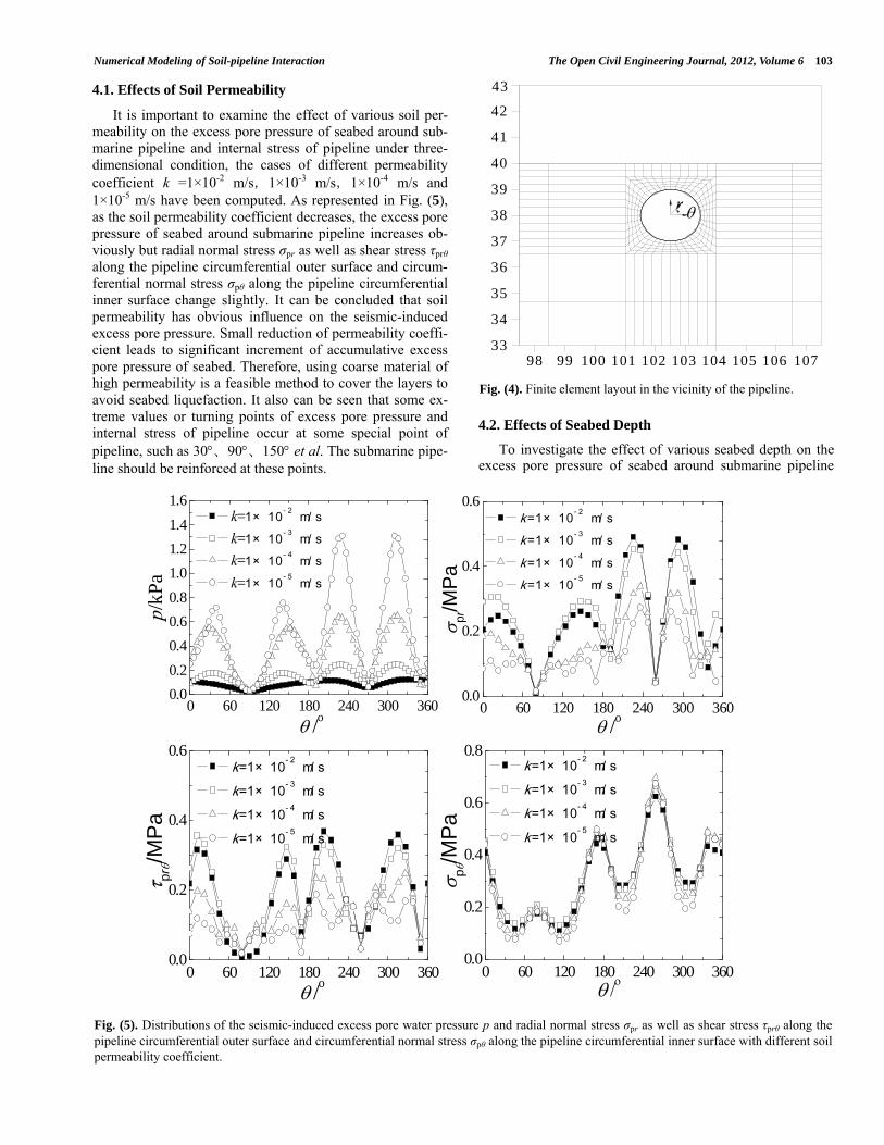
4.1. Effects of Soil Permeability
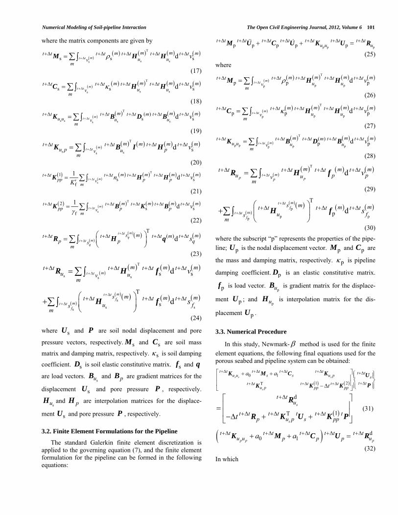
Fig. (4). Finite element layout in the vicinity of the pipeline.
It is important to examine the effect of various soil per-meability on the excess pore pressure of seabed around sub-marine pipeline and internal stress of pipeline under three-dimensional condition, the cases of different permeability coefficient k =1×10⁻² m/s,1×10-3 m/s,1×10-4 m/s and 1×10⁻⁵ m/s have been computed. As represented in Fig. (5), as the soil permeability coefficient decreases, the excess pore pressure of seabed around submarine pipeline increases ob-viously but radial normal stress σpr as well as shear stress τprθ along the pipeline circumferential outer surface and circum-ferential normal stress σpθ along the pipeline circumferential inner surface change slightly. It can be concluded that soil permeability has obvious influence on the seismic-induced excess pore pressure. Small reduction of permeability coeffi-cient leads to significant increment of accumulative excess pore pressure of seabed. Therefore, using coarse material of high permeability is a feasible method to cover the layers to avoid seabed liquefaction. It also can be seen that some ex-treme values or turning points of excess pore pressure and internal stress of pipeline occur at some special point of pipeline, such as 30、90、150 et al. The submarine pipe-line should be reinforced at these points.
4.2. Effects of Seabed Depth
To investigate the effect of various seabed depth on the excess pore pressure of seabed around submarine pipeline
Fig. (5). Distributions of the seismic-induced excess pore water pressure p and radial normal stress σpr as well as shear stress τprθ along the pipeline circumferential outer surface and circumferential normal stress σpθ along the pipeline circumferential inner surface with different soil permeability coefficient.
98 99 100 101 102 103 104 105 106 10733
34
35
36
37
38
39
40
41
42
43
r
0 60 120 180 240 300 3600.0
0.2
0.4
0.6
0.8
1.0
1.2
1.4
1.6 k=1× 10- 2 m/ s
k=1× 10- 3 m/ s
k=1× 10- 4 m/ s
k=1× 10- 5 m/ s
/o
p/kP
a
0 60 120 180 240 300 3600.0
0.2
0.4
0.6 k =1× 10- 2 m/ s
k =1× 10- 3 m/ s
k =1× 10- 4 m/ s
k =1× 10- 5 m/ s
pr/M
Pa
/o
0 60 120 180 240 300 3600.0
0.2
0.4
0.6 k=1× 10- 2 m/ s
k=1× 10- 3 m/ s
k=1× 10- 4 m/ s
k=1× 10- 5 m/ s
/o
p
r/M
Pa
0 60 120 180 240 300 3600.0
0.2
0.4
0.6
0.8 k=1× 10- 2 m/ s
k=1× 10- 3 m/ s
k=1× 10- 4 m/ s
k=1× 10- 5 m/ s
p/M
Pa

104 The Open Civil Engineering Journal, 2012, Volume 6 Zhang and Jeng
and internal stress of pipeline under three-dimensional condi-tion, different seabed depth cases of h = 15 m, 20 m and 30 m have been considered. From Fig. (6), it can be concluded that the excess pore pressure of seabed around submarine pipeline and internal stresses of submarine pipeline decrease gradually as the seabed depths increase. Because submarine pipeline is buried in a shallow depth of seabed, the deeper the seabed is, the further submarine pipeline is closer to the seismic hypocenter, the bigger the seismic responses are. It also can be seen that some extreme values or turning points of excess pore pressure and internal stress of pipeline occur at some special point of pipeline.
4.3. Effects of Pipeline Radius
Fig. (7) indicates that the distributions of the seismic-induced excess pore water pressure p and radial normal stress σpr as well as shear stress τprθ along the pipeline cir-cumferential outer surface and circumferential normal stress σpθ along the pipeline circumferential inner surface with var-ious pipeline radii R = 0.5 m, 1.0 m and 1.5 m. It is also ob-served from the Fig. (7) that four stresses increase on the whole with the pipeline radius increasing, but the excess pore pressure of seabed around submarine pipeline does not increase obviously. Radial normal stress σpr decreases slight-ly in upper part of pipeline (0<<180) but increases obvi-ously in lower part of pipeline (180<<360) with the pipe-line radius increasing. The reasons may be that increasing radius of the pipeline reduces the z-coordinate in the upper regions of submarine pipeline, but increases the z-coordinate in the lower regions of submarine pipeline. Shear stress τprθ along the pipeline circumferential outer surface and circum-
ferential normal stress σpθ along the pipeline circumferential inner surface increase obviously at majority points, particu-larly at special points.
4.4. Effects of Burial Depth
The effects of various values of burial depth b (b = 1m, 2m and 3m) on the distributions of the seismic-induced ex-cess pore water pressure p and radial normal stress σpr as well as shear stress τprθ along the pipeline circumferential outer surface and circumferential normal stress σpθ along the pipeline circumferential inner surface are examined in Fig. (8). From Fig. (8) it can be concluded that four stresses increase regularly as the burial depth increases. The same reasons as above, increasing burial depths of the pipeline makes the z-coordinates of seabed and submarine pipeline increase, therefore the excess of pore pressure and internal stresses all increase. The burial depths of submarine pipeline have remarkable effect on excess pore pressure and internal stresses.
5. CONCLUSIONS
The main contribution of this paper is to establish a three-dimensional model including buried pipeline based on the existing DYNE3WAC models. The effects of pipeline geometry and soil characteristics on the seismic-induced excess pore pressure of the seabed and internal stresses of submarine pipeline are discussed through the numerical model presented. Through numerical computations, the fol-lowing conclusions can be drawn:
1) The effect of permeability coefficient of soil on seismic-
Fig. (6). Distributions of the seismic-induced excess pore water pressure p and radial normal stress σpr as well as shear stress τprθ along the pipeline circumferential outer surface and circumferential normal stress σpθ along the pipeline circumferential inner surface with different seabed depth.
0 60 120 180 240 300 3600
10
20
30
40
50 h=15 m h=20 m h=30 m
/o
p/kP
a
0 60 120 180 240 300 3600
1
2
3
4
5 h=15 m h=20 m h=30 m
pr/M
Pa
/o
0 60 120 180 240 300 3600.0
0.1
0.2
0.3
0.4
0.5
h=15 m h=20 m h=30 m
/o
pr/M
Pa
0 60 120 180 240 300 3600
2
4
6
8
10
h=15 m h=20 m h=30 m
p/
MP
a

Numerical Modeling of Soil-pipeline Interaction The Open Civil Engineering Journal, 2012, Volume 6 105
Fig. (7). Distributions of the seismic-induced excess pore water pressure p and radial normal stress σpr as well as shear stress τprθ along the pipeline circumferential outer surface and circumferential normal stress σpθ along the pipeline circumferential inner surface with different radius of the pipeline.
Fig. (8). Distributions of the seismic-induced excess pore water pressure p and radial normal stress σpr as well as shear stress τprθ along the pipeline circumferential outer surface and circumferential normal stress σpθ along the pipeline circumferential inner surface with different pipeline burial depth.
induced excess pore pressure of seabed and internal stresses of submarine pipeline is remarkable. Using coarse material of high permeability is a feasible method to cover the layers to avoid seabed liquefaction.
2) Seabed depth, pipeline radius and burial depth of pipe-line have some influence on excess pore pressure of seabed and internal stresses of submarine pipeline.
3) Some extreme values or turning points of excess pore pressure and internal stress of pipeline occur at some
0 60 120 180 240 300 3600.0
0.1
0.2
0.3
0.4
0.5 R=1.0 m R=1.5 m R=2.0 m
/op/
kPa
0 60 120 180 240 300 3600.0
0.2
0.4
0.6
0.8
1.0 R=1.0 m R=1.5 m R=2.0 m
pr/M
Pa
/o
0 60 120 180 240 300 3600.0
0.1
0.2
0.3
0.4
0.5 R=1.0 m R=1.5 m R=2.0 m
/o
p
r/M
Pa
0 60 120 180 240 300 3600.0
0.2
0.4
0.6
0.8
1.0
1.2
1.4 R=1.0 m R=1.5 m R=2.0 m
p
/M
Pa
0 60 120 180 240 300 3600.0
0.2
0.4
0.6
0.8
1.0 b=1.0 m b=2.0 m b=3.0 m
/o
p/kP
a
0 60 120 180 240 300 3600.0
0.2
0.4
0.6
0.8
1.0
b=1.0 m b=2.0 m b=3.0 m
pr/M
Pa
/o
0 60 120 180 240 300 3600.0
0.2
0.4
0.6
0.8
1.0 b=1.0 m b=2.0 m b=3.0 m
/o
p
r/M
Pa
0 60 120 180 240 300 3600.0
0.2
0.4
0.6
0.8
1.0 b=1.0 m b=2.0 m b=3.0 m
p/M
Pa

106 The Open Civil Engineering Journal, 2012, Volume 6 Zhang and Jeng
special point of pipeline, such as 30、90、150 et al. Submarine pipeline should be reinforced at these points.
CONFLICTS OF INTEREST
The authors confirm that this article content has no con-flicts of interest.
ACKNOWLEDGEMENTS
The authors wish to express their gratitude to China Scholarship Council for sponsoring this study in University of Dundee, the supports from the Scientific Research Foun-dation for Doctor of Beijing University of Technology and the supports from Science and Technology Activity Founda-tion for Returned Overseas Students of Beijing are mostly grateful. This research has been also suppported by state key Laboratory of Ocean Engineering (Shanghai Jiao Tong Uni-versity) (Grant No.1112).
REFERENCES
[1] D. H .Lee, B .H .Kim, H. Lee and J. S. Kong, “Seismic behavior of a buried gas pipeline under earthquake excitations”, Eng. Struct., vol. 31, pp. 1011-1023, 2009.
[2] N. M. Newmark and E. Rosenblueth, Fundamentals of earthquake engineering, Prentice-Hall: Englewood Cliffs,1971.
[3] W. J. Hall and N. M. Newmark, “Seismic design criteria for pipe-lines and facilities, the current state of knowledge of lifeline”, Earthquake Eng., vol. 103, pp. 18-34, 1977.
[4] G. D. Manolis, P. I. Tetepoulidis, D. G. Talaslidis and G. Apos-tolidis, “Seismic analysis of buried pipeline in a 3D soil contin-uum”, Eng. Anal. Bound. Elements, vol. 15, pp. 371-394, 1995.
[5] H. B. Liu and E. X. Song, “Seismic response of large underground structure in liquefiable soil subjected to horizontal and vertical earthquake excitations”, Comp. Geotech., vol. 32, pp. 223-244, 2005.
[6] K. C. Wong, A. H. Shah and S. K. Datta, “Three dimensional mo-tion of buried pipeline”, J. Eng. Mech., vol. 112, pp. 1319-1348, 1986.
[7] D. G. Zou, X. J. Kong, S. L. Lou and T. Zhang, “Numerical simu-lation of shaking table test on pipelines buried in saturated sand foundation”, J. Hydr. Eng., vol. 12, pp. 112-119, 2004.
[8] J. H. Ou, “Three-dimensional numerical modeling of interaction between soil and pore fluid”, Ph.D thesis, University of Birming-ham, Birmingham, U.K., 2009.
[9] M. A. Biot, “Theory of propagation of elastic waves in a fluid-saturated porous solid, part Ⅱ-low-frequency range, part Ⅱ-higher-frequency range”, J. Acoust. Soc. Am., vol. 28, no.2, pp. 168-178, 1956.
[10] W. Magda, “Wave-induced uplift force acting on a submarine buried pipeline in a compressible seabed”, Ocean Eng., vol. 24, no.6, pp. 551-576, 1997.
[11] H. C. Chan, User manual for DIANA-SWANDYNE Ⅱ. Department of Civil Engineering, University of Birmingham Press: UK, 1995.
[12] O. C. Zienkiewicz, A. H. C. Chan, M. Pastor, B. A. Schrefler and T. Shiomi, Computational Geomechanics with special reference to earthquake engineering. Wiley: Chichester, U.K., 1999.
[13] O. C. Zienkiewicz, A. H. C. Chan, M. Pastor, D. K. Paul, and T. Shiomi, “Static and dynamic behaviour of geomaterials-A rational approach to quantitative solutions. Part I: Fully saturated problems” Proc. R. Soc. London Sr. A, vol. 429, pp. 285-309, 1990.
[14] D. S. Jeng and H. Zhang, “An integrated three-dimensional model of wave-induced pore pressure and effective stresses in a porous seabed: II. Breaking waves”, Ocean Eng., vol. 32, no.16, pp. 1950-1967, 2005.
[15] H. Zhang and D.S. Jeng, “An integrated three-dimensional model for wave-induced seabed response in a porous seabed: I. A sloping seabed”, Ocean Eng., vol. 32, pp. 701-729, 2005.
[16] X. L. Zhang, D. S. Jeng and M. T. Luan, “Dynamic response of a porous seabed around pipeline under three-dimensional wave load-ing”, Soil Dyn. Earthquake Eng., vol. 31, no.5-6, pp. 785-791, 2011.
[17] L. L. Xie and C. H. Zhai, “Study on the severest real ground mo-tion for seismic design and analysis”, Acta Seismologica Sinica, vol. 25, no.3, pp. 250-261, 2003.
[18] Z. Y. XU, “An evaluation method of pore pressure during earth-quake”, J. Hydraulic Eng., vol. 4, pp. 68-73, 1981.
[19] W. Magda, “Wave-induced uplift force acting on a submarine buried pipeline: finite element formulation and verification of com-putations”, Comp. Geotech., vol. 19, no.1, pp. 47-53, 1996.
Received: July 14, 2012 Revised: July 19, 2012 Accepted: July 24, 2012
© Zhang and Jeng; Licensee Bentham Open.
This is an open access article licensed under the terms of the Creative Commons Attribution Non-Commercial License (http://creativecommons.org/licenses/ by-nc/3.0/) which permits unrestricted, non-commercial use, distribution and reproduction in any medium, provided the work is properly cited.


![Densely rooted rhizosphere hotspots induced around ...stressconditions[14–17].esePGPMshavealsobeen showntosynthesizevariousantifungalmetabolites(e.g. phenolsandphenazines)thatdirectlysuppressrootpath](https://static.fdocuments.in/doc/165x107/5a827e877f8b9a24668dc50f/densely-rooted-rhizosphere-hotspots-induced-around-stressconditions1417esepgpmshavealsobeen.jpg)