Numerical investigation of suction vortices behavior in ... · Numerical investigation of suction...
6
Journal of Mechanical Science and Technology 25 (3) (2011) 767~772 www.springerlink.com/content/1738-494x DOI 10.1007/s12206-011-0108-6 Numerical investigation of suction vortices behavior in centrifugal pump † Young-Joon An 1 and Byeong Rog Shin 2,* 1 Department of Mechanical Engineering, Graduate School, Changwon National University, Changwon 641-773, Korea 2 Department of Mechanical Engineering, Changwon National University, Changwon 641-773, Korea (Manuscript Received December 6, 2010; Revised January 4, 2011; Accepted January 4, 2011) ---------------------------------------------------------------------------------------------------------------------------------------------------------------------------------------------------------------------------------------------------------------------------------------------- Abstract A numerical simulation on suction vortices behavior in a centrifugal pump was carried out to investigate their influence on the internal flow through impellers including formation and shedding of cavitation by using a finite-volume method and k-ω Shear Stress Transport turbulence model. For cavitating flow, a two phase homogeneous cavitation model was used. A full three-dimensional flow in a single- section centrifugal pump consisting of a six blade impeller and shroud ring was computed with structured mesh. A constant suction vor- tex is imposed as a boundary condition. Vortices behavior was investigated according to the variation of flow rates of two pump systems with and without suction vortices. From the results, suction vortices induced biased flow structure and more cavitations, especially at the low flow rate condition. Complicated internal flow phenomena through impellers such as formation of cavitations, growing and shedding of the vortex, flow separation and flow unsteadiness due to the suction vortices are investigated and discussed. Keywords: Centrifugal pump; Suction vortices; Cavitation; Void fraction; Flow unsteadiness; Computational fluid dynamics ---------------------------------------------------------------------------------------------------------------------------------------------------------------------------------------------------------------------------------------------------------------------------------------------- 1. Introduction The centrifugal pump is a very important fluid machinery which delivers energy to a fluid by impeller. This machine system is used commonly in industry because it has a simple structure and covers a wide range of discharge flow rates and heads. However, in the centrifugal pump, cavitation, flow separation, pressure loss, vibration and noise often occur due to flow unsteadiness and abnormality during operation. Espe- cially, air-entrained and submerged vortices often observed in sump pumps have a great effect on pump performance and could seriously damage a pump system. Therefore, in the con- struction of a pump station, these vortices are not permitted, and their disappearance must be verified by the pump sump model test [1, 2]. For an advanced pump design to have high performance and safety, it is very important to know the de- tailed flow information and understand the flow field in pump at an earlier stage. For this purpose, many researchers have studied the per- formance analysis of centrifugal pumps to this day. Kim et al.[3] carried out numerical analyses of single-suction cen- trifugal pump by the CFX commercial code. Shim et al.[4] evaluated flow characteristics using STAR-CD and Tascflow in accordance with different turbulent models. Also, Kim et al. [5] performed flow visualization around the impeller by using PIV measurement. In general they simulated or checked the overall flow information and characteristics for given cen- trifugal pumps. On the other hand, as a study of suction vortices in pump sumps, Iwano et al.[6] introduced a numerical method for a submerged vortex and cavitation. They applied the SMAC and the QUICK schemes to the flow in pump sumps with and without baffle plates. To obtain a high resolution of the vortex, a kind of vortex model is adopted and reproduced as vortex structure. Chen and Guo [7] simulated a three-dimensional flow in the sump of the pump station with multi-intakes by using the FLUENT software. By imposing a suitable bound- ary condition for the flow in the sump with several water in- takes at different flow rates as well as water levels, they re- ported that predicted velocity profiles at several sections of sump could be compared well with experiments. Regarding the prediction of suction vortices, recently Okamura et al.[8] performed a benchmark test by using several CFD commer- cial codes and reviewed the results to check their applicability to the design of the pump station instead of the expensive conventional experimental method. Like this, for detailed investigations and parametric studies to increase pump per- formance such as efficiency, head and shaft power, numerical simulation is very useful and effective. In this paper, a numerical simulation on suction vortices † This paper was recommended for publication in revised form by Associate Editor Do Hyung Lee * Corresponding author. Tel.: +82 55 213 3609, Fax.: +82 55 275 0101 E-mail address: [email protected] © KSME & Springer 2011
Transcript of Numerical investigation of suction vortices behavior in ... · Numerical investigation of suction...
Journal of Mechanical Science and Technology 25 (3) (2011) 767~772
www.springerlink.com/content/1738-494x DOI 10.1007/s12206-011-0108-6
Numerical investigation of suction vortices behavior in centrifugal pump†
Young-Joon An1 and Byeong Rog Shin2,* 1Department of Mechanical Engineering, Graduate School, Changwon National University, Changwon 641-773, Korea
2Department of Mechanical Engineering, Changwon National University, Changwon 641-773, Korea
(Manuscript Received December 6, 2010; Revised January 4, 2011; Accepted January 4, 2011)
----------------------------------------------------------------------------------------------------------------------------------------------------------------------------------------------------------------------------------------------------------------------------------------------
Abstract A numerical simulation on suction vortices behavior in a centrifugal pump was carried out to investigate their influence on the internal
flow through impellers including formation and shedding of cavitation by using a finite-volume method and k-ω Shear Stress Transport turbulence model. For cavitating flow, a two phase homogeneous cavitation model was used. A full three-dimensional flow in a single-section centrifugal pump consisting of a six blade impeller and shroud ring was computed with structured mesh. A constant suction vor-tex is imposed as a boundary condition. Vortices behavior was investigated according to the variation of flow rates of two pump systems with and without suction vortices. From the results, suction vortices induced biased flow structure and more cavitations, especially at the low flow rate condition. Complicated internal flow phenomena through impellers such as formation of cavitations, growing and shedding of the vortex, flow separation and flow unsteadiness due to the suction vortices are investigated and discussed.
Keywords: Centrifugal pump; Suction vortices; Cavitation; Void fraction; Flow unsteadiness; Computational fluid dynamics ---------------------------------------------------------------------------------------------------------------------------------------------------------------------------------------------------------------------------------------------------------------------------------------------- 1. Introduction
The centrifugal pump is a very important fluid machinery which delivers energy to a fluid by impeller. This machine system is used commonly in industry because it has a simple structure and covers a wide range of discharge flow rates and heads. However, in the centrifugal pump, cavitation, flow separation, pressure loss, vibration and noise often occur due to flow unsteadiness and abnormality during operation. Espe-cially, air-entrained and submerged vortices often observed in sump pumps have a great effect on pump performance and could seriously damage a pump system. Therefore, in the con-struction of a pump station, these vortices are not permitted, and their disappearance must be verified by the pump sump model test [1, 2]. For an advanced pump design to have high performance and safety, it is very important to know the de-tailed flow information and understand the flow field in pump at an earlier stage.
For this purpose, many researchers have studied the per-formance analysis of centrifugal pumps to this day. Kim et al.[3] carried out numerical analyses of single-suction cen-trifugal pump by the CFX commercial code. Shim et al.[4] evaluated flow characteristics using STAR-CD and Tascflow
in accordance with different turbulent models. Also, Kim et al. [5] performed flow visualization around the impeller by using PIV measurement. In general they simulated or checked the overall flow information and characteristics for given cen-trifugal pumps.
On the other hand, as a study of suction vortices in pump sumps, Iwano et al.[6] introduced a numerical method for a submerged vortex and cavitation. They applied the SMAC and the QUICK schemes to the flow in pump sumps with and without baffle plates. To obtain a high resolution of the vortex, a kind of vortex model is adopted and reproduced as vortex structure. Chen and Guo [7] simulated a three-dimensional flow in the sump of the pump station with multi-intakes by using the FLUENT software. By imposing a suitable bound-ary condition for the flow in the sump with several water in-takes at different flow rates as well as water levels, they re-ported that predicted velocity profiles at several sections of sump could be compared well with experiments. Regarding the prediction of suction vortices, recently Okamura et al.[8] performed a benchmark test by using several CFD commer-cial codes and reviewed the results to check their applicability to the design of the pump station instead of the expensive conventional experimental method. Like this, for detailed investigations and parametric studies to increase pump per-formance such as efficiency, head and shaft power, numerical simulation is very useful and effective.
In this paper, a numerical simulation on suction vortices
†This paper was recommended for publication in revised form by Associate EditorDo Hyung Lee
*Corresponding author. Tel.: +82 55 213 3609, Fax.: +82 55 275 0101 E-mail address: [email protected]
© KSME & Springer 2011
768 Y. J. An and B. R. Shin / Journal of Mechanical Science and Technology 25 (3) (2011) 767~772
behavior in a centrifugal pump is performed, and their influ-ence on the internal flow through impellers including forma-tion, growing, and shedding of cavitation is investigated. Suc-tion vortices are generated by means of boundary condition imposed at the given inlet place of impeller. And then, the vortices behavior and their influences are investigated at sev-eral points of flow rate for the two cases with and without suction vortices. 2. Numerical method
A numerical analysis of three-dimensional (3-D) incom-pressible flow through a single-suction centrifugal pump is performed by using the finite volume method of the CFX code [9] and multi-block structured grid systems. Fig. 1 shows a solid model of impeller blades and computational grid. Present centrifugal pump consisted of six blades impeller and a shroud ring. The rotating speed of closed type impeller is 1500 rpm. Computational grid generated by using Turbo-grid software has 8x10⁵ points and its mesh density is high around the blades.
Fundamental equations are the continuity equation and the Reynolds Averaged Navier-Stokes (RANS) equations as the following;
0∇ ⋅ =u 1( ) ( ).effp
tν
ρ∂
+ ∇ ⋅ = − ∇ +∇ ⋅ ∇∂u uu u
Here, ρ and u are fluid density and velocity. t is time and
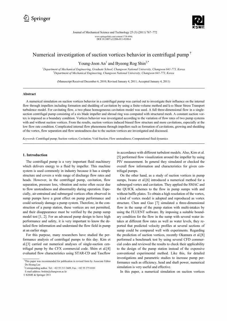
effν is effective kinetic viscosity considered molecular viscos-ity and turbulent viscosity. A k-ω shear stress transport turbu-lence model and a homogeneous cavitation model were used for solving turbulence cavitating flow. The working fluid is turbine oil which has a density of 868.2 kg/m3 and a viscosity of 0.027 kg/ms. As the boundary condition, constant total pressure is imposed at the impeller outlet and flow rate is ap-plied at inlet. In addition, suction vortices are given as an inlet boundary condition at a given region on inlet plane. A predic-tion by the present computation for the pump characteristics expressed by the flow coefficient, head coefficient, power coefficient and overall efficiency is shown in Fig. 2. From this figure, we know that it has very reasonable pump characteris-tics because the present test pump is relatively well designed and is actually used in the industries.
3. Numerical results
3.1 In the case without suction vortices
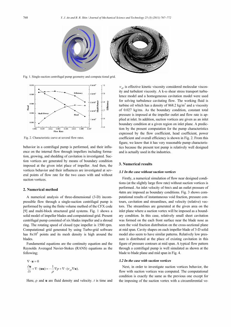
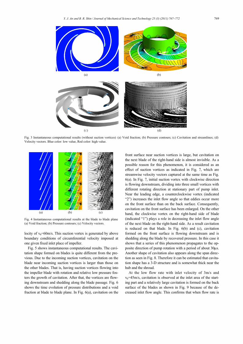
Firstly, a numerical simulation of flow near designed condi-tions (at the slightly large flow rate) without suction vortices is performed. An inlet velocity of 6m/s and an outlet pressure of 4atm are imposed as boundary conditions. Fig. 3 shows com-putational results of instantaneous void fraction, pressure con-tours, cavitation and streamlines, and velocity (relative) vec-tors. The streamlines are generated at the given area on the inlet plane where a suction vortex will be imposed as a bound-ary condition. In this case, relatively small sheet cavitation was formed on the each front surface near the blade nose as seen the void fraction distribution on the cross-sectional plane at mid span. Cavity shapes on each impeller blade of 3-D solid model also seem to have similar patterns. Relatively low pres-sure is distributed at the place of existing cavitation in this figure of pressure contours at mid span. A typical flow pattern through a centrifugal pump is well simulated as shown at the blade to blade plane and mid span in Fig. 4. 3.2 In the case with suction vortices
Next, in order to investigate suction vortices behavior, the flow with suction vortices was computed. The computational condition is exactly the same as the previous one except for the imposing of the suction vortex with a circumferential ve-
Fig. 2. Characteristic curve at several flow rates.
Fig. 1. Single-suction centrifugal pump geometry and computa tional grid.
Y. J. An and B. R. Shin / Journal of Mechanical Science and Technology 25 (3) (2011) 767~772 769
locity of vθ=60m/s. This suction vortex is generated by above boundary conditions of circumferential velocity imposed at one given fixed inlet place of impeller.
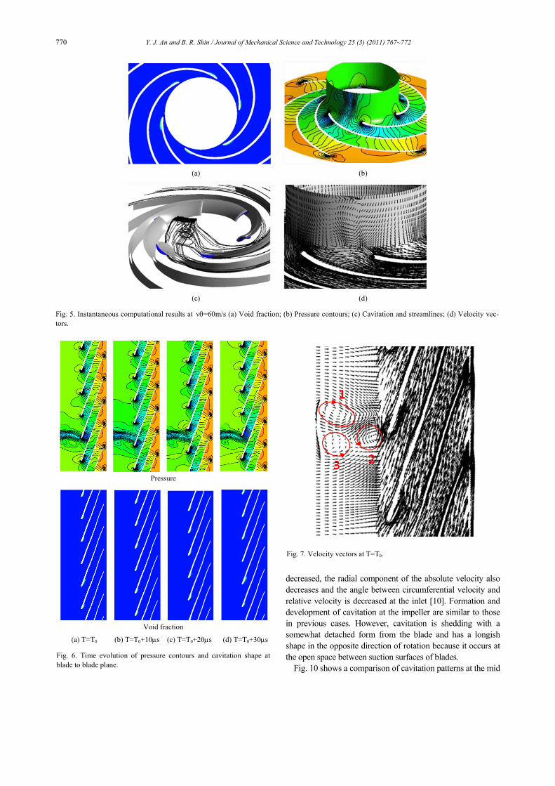
Fig. 5 shows instantaneous computational results. The cavi-tation shape formed on blades is quite different from the pre-vious. Due to the incoming suction vortices, cavitation on the blade near incoming suction vortices is larger than those on the other blades. That is, having suction vortices flowing into the impeller blade with rotation and relative low pressure fos-ters the growth of cavitation. After that, the vortices are flow-ing downstream and shedding along the blade passage. Fig. 6 shows the time evolution of pressure distributions and a void fraction at blade to blade plane. In Fig. 6(a), cavitation on the
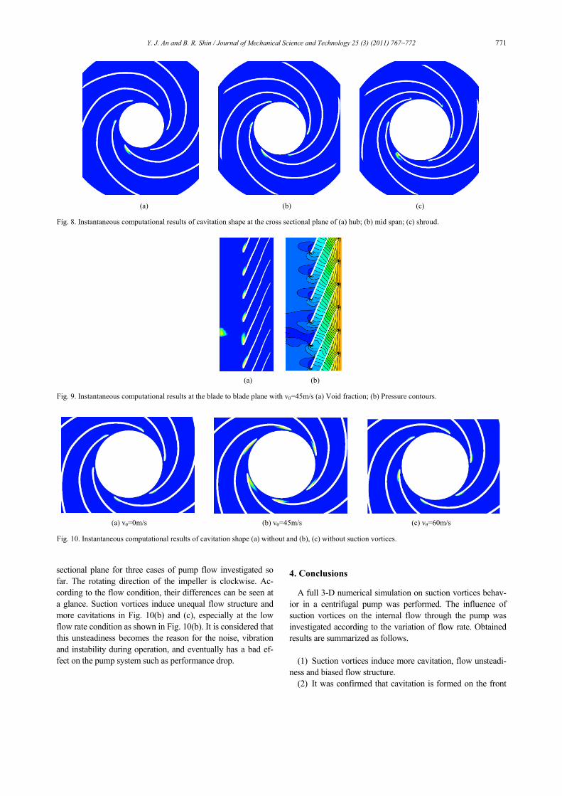
front surface near suction vortices is large, but cavitation on the next blade of the right-hand side is almost invisible. As a possible reason for this phenomenon, it is considered as an effect of suction vortices as indicated in Fig. 7, which are streamwise velocity vectors captured at the same time as Fig. 6(a). In Fig. 7, initial suction vortex with clockwise direction is flowing downstream, dividing into three small vortices with different rotating direction at stationary part of pump inlet. Near the leading edge, a counterclockwise vortex (indicated “2”) increases the inlet flow angle so that eddies occur more on the front surface than on the back surface. Consequently, cavitation on the front surface has been enlarged. On the other hand, the clockwise vortex on the right-hand side of blade (indicated “1”) plays a role in decreasing the inlet flow angle of the next blade on the right-hand side. As a result cavitation is reduced on that blade. In Fig. 6(b) and (c), cavitation formed on the front surface is flowing downstream and is shedding along the blade by recovered pressure. In this case it shows that a series of this phenomenon propagates to the op-posite direction of pump rotation with a period of about 30μs. Another shape of cavitation also appears along the span direc-tion as seen in Fig. 8. Therefore it can be estimated that cavita-tion shape has a 3-D structure and is somewhat thick near the hub and the shroud.
At the low flow rate with inlet velocity of 3m/s and vθ=45m/s, cavitation is observed at the inlet area of the start-ing part and a relatively large cavitation is formed on the back surface of the blades as shown in Fig. 9 because of the de-creased inlet flow angle. This confirms that when flow rate is
(a) (b)
(c) (d) Fig. 3 Instantaneous computational results (without suction vortices) (a) Void fraction; (b) Pressure contours; (c) Cavitation and streamlines; (d)Velocity vectors. Blue color: low value, Red color: high value.
(a) (b) (c) Fig. 4 Instantaneous computational results at the blade to blade plane(a) Void fraction; (b) Pressure contours; (c) Velocity vectors.
770 Y. J. An and B. R. Shin / Journal of Mechanical Science and Technology 25 (3) (2011) 767~772
decreased, the radial component of the absolute velocity also decreases and the angle between circumferential velocity and relative velocity is decreased at the inlet [10]. Formation and development of cavitation at the impeller are similar to those in previous cases. However, cavitation is shedding with a somewhat detached form from the blade and has a longish shape in the opposite direction of rotation because it occurs at the open space between suction surfaces of blades.
Fig. 10 shows a comparison of cavitation patterns at the mid
(a) (b)
(c) (d) Fig. 5. Instantaneous computational results at vθ=60m/s (a) Void fraction; (b) Pressure contours; (c) Cavitation and streamlines; (d) Velocity vec-tors.
Pressure
Void fraction
(a) T=T0 (b) T=T0+10μs (c) T=T0+20μs (d) T=T0+30μs Fig. 6. Time evolution of pressure contours and cavitation shape at blade to blade plane.
Fig. 7. Velocity vectors at T=T0.
Y. J. An and B. R. Shin / Journal of Mechanical Science and Technology 25 (3) (2011) 767~772 771
sectional plane for three cases of pump flow investigated so far. The rotating direction of the impeller is clockwise. Ac-cording to the flow condition, their differences can be seen at a glance. Suction vortices induce unequal flow structure and more cavitations in Fig. 10(b) and (c), especially at the low flow rate condition as shown in Fig. 10(b). It is considered that this unsteadiness becomes the reason for the noise, vibration and instability during operation, and eventually has a bad ef-fect on the pump system such as performance drop.
4. Conclusions
A full 3-D numerical simulation on suction vortices behav-ior in a centrifugal pump was performed. The influence of suction vortices on the internal flow through the pump was investigated according to the variation of flow rate. Obtained results are summarized as follows.
(1) Suction vortices induce more cavitation, flow unsteadi-
ness and biased flow structure. (2) It was confirmed that cavitation is formed on the front
(a) (b) (c) Fig. 8. Instantaneous computational results of cavitation shape at the cross sectional plane of (a) hub; (b) mid span; (c) shroud.
(a) (b) Fig. 9. Instantaneous computational results at the blade to blade plane with vθ=45m/s (a) Void fraction; (b) Pressure contours.
(a) vθ=0m/s (b) vθ=45m/s (c) vθ=60m/s Fig. 10. Instantaneous computational results of cavitation shape (a) without and (b), (c) without suction vortices.
772 Y. J. An and B. R. Shin / Journal of Mechanical Science and Technology 25 (3) (2011) 767~772
surface of blades at relatively large flow rate, but is also formed at the back surface at relatively low flow rate.
(3) Suction vortices act to increase inlet flow angle bring more eddies on the front surface of blades.
(4) Cavitation formed on back surface of the blades sheds with a detached shape from the blade and has a longish shape to the opposite direction of rotation.
(5) Present computation with full 3-D flow model simu-lated complicated asymmetric flow phenomena in centrifugal pump with and without suction vortices pretty well.
Acknowledgment
This research is financially supported by Underwater Vehi-cle Research Center (UVRC), ADD of Korea and Changwon National University in 2009-2010.
References
[1] Hydraulic Institute Standards, American National Standard for Pump Intake Design, ANSI/HI 9.8 (1998).
[2] Standard Method for Model Testing the Performance of a Pump Sump, JSME S 004 (1984).
[3] M.S. Kim, B.S. Kim, J.G. Kim, K.H. Park and Y.H. Lee, A Study on the Performance Analysis of an Industrial Cen-trifugal Pump Using CFX Code, Proc. The Korean Society of Marine Engineering Conference (2005) 174-175.
[4] C.Y. Shim, S. S. Hong and S. H. Kang, Flow Evaluations of Centrifugal Pump Impeller Using Commercial Code, Proc. the KFMA Annual Meeting (2000) 285-292.
[5] J.H. Kim, M.S. Choi, J.G. Kim and Y.H. Lee, A Study on Flow and Efficiency Characteristics in Guide Vane of Dif-fuser Pump Using PIV Measurement, Proc. the KFMA An-nual Meeting (2000) 29-35.
[6] R. Iwano, T. Shibata, T. Nagahara and T. Okamura, Nu-merical Prediction Method of a Submerged Vortex and Its Application to the Flow in Pump Sumps with and without a
Baffle Plate, Proc. 9th Int’l Symp. On Transport Phenomena and Dyn. of Rotating Machinery (2002) 1-6.
[7] H. Chen and J. Guo, Numerical Simulation of 3-D Turbulent Flow in the Multi-Intakes Sump of the Pump Station, J. of Hydrodynamics, Ser. B, 19 (2007) 42-47.
[8] T. Okamura, K. Kamemoto and J. Matsui, CFD Prediction and Model Experiment on Suction Vortices in Pump Sump, Proc. 9th Asian Int’l Conf. on Fluid Machinery, AICFM9-053 (2007) 1-10.
[9] Ansys, CFX User’s manual, Version 11 ( 2007). [10] A.T. Sayers, Hydraulic and Compressible Flow Turbo-
machines, McGraw-Hill, New York, USA (1988).
Young-Joon An received his M.S in Mechanical Engineering from the Changwon National University in 2007. Mr. An is currently a Ph.D. candidate at the Department of Mechanical Engineer-ing at Changwon National University in Changwon, Korea. Mr. An’s research interests are in the area of pumps and
hydraulic turbines.
Byeong Rog Shin received his Ph.D. in Mechanical Engineering from Tohoku University, Sendai, Japan, in 1991. He is currently a full professor in the Depart-ment of Mechanical Engineering, Changwon National University, Chang-won, Korea. His research interests are in the areas of CFD to develop numerical
schemes for the compressible/incompressible viscous flows and the gas-liquid two-phase flows, as well as in the areas of the numerical simulation for the prediction, optimal design and the improvement of the performance of turbomachinery systems.