Numerical investigation of nonlinear static and dynamic ...
14
Soil Dynamics and Earthquake Engineering 128 (2020) 105876 Available online 30 September 2019 0267-7261/© 2019 The Authors. Published by Elsevier Ltd. This is an open access article under the CC BY-NC-ND license (http://creativecommons.org/licenses/by-nc-nd/4.0/). Numerical investigation of nonlinear static and dynamic behaviour of self-centring rocking segmental bridge piers Ehsan Ahmadi * , Mohammad M. Kashani Faculty of Engineering and Physical Sciences, University of Southampton, UK A R T I C L E INFO Keywords: Precast post-tensioned segmental piers Rocking mechanism Accelerated bridge construction Nonlinear dynamic Rocking dynamic Frequency response functions ABSTRACT Accelerated Bridge Construction (ABC) philosophy has resulted in extensive developments of precast post- tensioned segmental (PPS) bridge piers in the bridge construction. Currently, there is a significant paucity in the literature on nonlinear mechanics and dynamics of PPS piers. Hence, this wok numerically investigates the nonlinear static and dynamic behaviour of PPS piers using a finite element (FE) framework. Nonlinear static and dynamic analyses are performed, and the results are compared for non-tapered and tapered PPS as well as cast- in-place (CIP) piers. It is found that post-tensioning force, aspect ratio, axial force of the pier, and number of segments highly affect nonlinear behaviour of the PPS piers. High levels of excitation amplitudes exhibit co- existing (high/low) amplitude responses at and around the resonant frequency of the PPS piers, and tapering enhances the probability of dynamic instability in the PPS pier. It is also shown that the fundamental mode of the PPS piers is similar to the first mode of a CIP bridge pier. 1. Introduction 1.1. Background Bridges are key nodes in any transport infrastructure, and any interruption in their operation can lead to enormous social, economic, and life losses. Particularly, seismic loading can induce permanent structural damage. Conventional cast-in-place (CIP) reinforced concrete (RC) piers are monolithically cast in foundation and may or may not be integrated to the bridge deck. Thus, plastic hinges are formed in such piers when subjected to earthquake loading i.e. permanent plastic de- formations. As an alternative to CIP piers, precast post-tensioned segmental (PPS) piers have recently received much attention ([1,2]), and are used in accelerated bridge construction (ABC) ([3,4]). The PPS piers have two main advantages: (i) offsite manufacturing, which en- hances manufacturing quality and reduces the construction time i.e. ABC, and (ii) the combined rocking mechanism of the segments and self-centring effect of the post-tensioned tendon significantly reduce the residual deformation remained in the pier after the loading events [5]. Such lower residual deformation will result in a more seismically resil- ient structure. It should be noted that the segments can still experience local damages at their contact interfaces. 1.2. Precast post-tensioned segmental piers Recently, many experimental studies have been carried out to address seismic behaviour of PPS piers mostly under static cyclic loading and rarely using dynamic testing protocols. Hewes [6] investigated seismic performance of PPS piers with different aspect ratios. It was concluded that PPS piers can effectively withstand seismic loading while dissipating limited energy. To enhance energy-dissipating capacity of PPS piers, different methods were suggested. Ou et al. [7] used contin- uous mild steel bars, known as energy dissipating (ED) bars, across the pier’s segments to improve dissipation capability of the system. Chou and Chen [8] proposed use of concrete-filled tubes as external dissi- paters and an increase was found in the equivalent damping ratio of the system. Marriott et al. [9] adopted external replaceable dissipaters which considerably increased the dissipation capacity of the PPS piers. Other studies also reported higher energy dissipation when the base segment is monolithically connected to the foundation [10]. The use of other dissipaters was also tested such as rubber pads [11], or built-in elastomer pads [12]. In a series of different studies, Sideris et al. ([13, 14]) introduced a novel PPS pier equipped with hybrid sliding-rocking joints. It should be noted that all these studies focused on mitigating seismic response and damage levels of the PPS pier, and no attempt was made to investigate the sources of nonlinearity in structural dynamics of * Corresponding author. E-mail address: [email protected] (E. Ahmadi). Contents lists available at ScienceDirect Soil Dynamics and Earthquake Engineering journal homepage: http://www.elsevier.com/locate/soildyn https://doi.org/10.1016/j.soildyn.2019.105876 Received 18 June 2019; Received in revised form 20 September 2019; Accepted 26 September 2019
Transcript of Numerical investigation of nonlinear static and dynamic ...

Soil Dynamics and Earthquake Engineering 128 (2020) 105876
Available online 30 September 20190267-7261/© 2019 The Authors. Published by Elsevier Ltd. This is an open access article under the CC BY-NC-ND license(http://creativecommons.org/licenses/by-nc-nd/4.0/).
Numerical investigation of nonlinear static and dynamic behaviour of self-centring rocking segmental bridge piers
Ehsan Ahmadi *, Mohammad M. Kashani Faculty of Engineering and Physical Sciences, University of Southampton, UK
A R T I C L E I N F O
Keywords: Precast post-tensioned segmental piers Rocking mechanism Accelerated bridge construction Nonlinear dynamic Rocking dynamic Frequency response functions
A B S T R A C T
Accelerated Bridge Construction (ABC) philosophy has resulted in extensive developments of precast post- tensioned segmental (PPS) bridge piers in the bridge construction. Currently, there is a significant paucity in the literature on nonlinear mechanics and dynamics of PPS piers. Hence, this wok numerically investigates the nonlinear static and dynamic behaviour of PPS piers using a finite element (FE) framework. Nonlinear static and dynamic analyses are performed, and the results are compared for non-tapered and tapered PPS as well as cast- in-place (CIP) piers. It is found that post-tensioning force, aspect ratio, axial force of the pier, and number of segments highly affect nonlinear behaviour of the PPS piers. High levels of excitation amplitudes exhibit co- existing (high/low) amplitude responses at and around the resonant frequency of the PPS piers, and tapering enhances the probability of dynamic instability in the PPS pier. It is also shown that the fundamental mode of the PPS piers is similar to the first mode of a CIP bridge pier.
1. Introduction
1.1. Background
Bridges are key nodes in any transport infrastructure, and any interruption in their operation can lead to enormous social, economic, and life losses. Particularly, seismic loading can induce permanent structural damage. Conventional cast-in-place (CIP) reinforced concrete (RC) piers are monolithically cast in foundation and may or may not be integrated to the bridge deck. Thus, plastic hinges are formed in such piers when subjected to earthquake loading i.e. permanent plastic de-formations. As an alternative to CIP piers, precast post-tensioned segmental (PPS) piers have recently received much attention ([1,2]), and are used in accelerated bridge construction (ABC) ([3,4]). The PPS piers have two main advantages: (i) offsite manufacturing, which en-hances manufacturing quality and reduces the construction time i.e. ABC, and (ii) the combined rocking mechanism of the segments and self-centring effect of the post-tensioned tendon significantly reduce the residual deformation remained in the pier after the loading events [5]. Such lower residual deformation will result in a more seismically resil-ient structure. It should be noted that the segments can still experience local damages at their contact interfaces.
1.2. Precast post-tensioned segmental piers
Recently, many experimental studies have been carried out to address seismic behaviour of PPS piers mostly under static cyclic loading and rarely using dynamic testing protocols. Hewes [6] investigated seismic performance of PPS piers with different aspect ratios. It was concluded that PPS piers can effectively withstand seismic loading while dissipating limited energy. To enhance energy-dissipating capacity of PPS piers, different methods were suggested. Ou et al. [7] used contin-uous mild steel bars, known as energy dissipating (ED) bars, across the pier’s segments to improve dissipation capability of the system. Chou and Chen [8] proposed use of concrete-filled tubes as external dissi-paters and an increase was found in the equivalent damping ratio of the system. Marriott et al. [9] adopted external replaceable dissipaters which considerably increased the dissipation capacity of the PPS piers. Other studies also reported higher energy dissipation when the base segment is monolithically connected to the foundation [10]. The use of other dissipaters was also tested such as rubber pads [11], or built-in elastomer pads [12]. In a series of different studies, Sideris et al. ([13, 14]) introduced a novel PPS pier equipped with hybrid sliding-rocking joints. It should be noted that all these studies focused on mitigating seismic response and damage levels of the PPS pier, and no attempt was made to investigate the sources of nonlinearity in structural dynamics of
* Corresponding author. E-mail address: [email protected] (E. Ahmadi).
Contents lists available at ScienceDirect
Soil Dynamics and Earthquake Engineering
journal homepage: http://www.elsevier.com/locate/soildyn
https://doi.org/10.1016/j.soildyn.2019.105876 Received 18 June 2019; Received in revised form 20 September 2019; Accepted 26 September 2019

Soil Dynamics and Earthquake Engineering 128 (2020) 105876
2
the system in forms of frequency response functions (FRFs). In different studies, high-damping material layers also were used between segments in small-scale columns inspired by mechanics of the human spine, and damping level of the system was highly improved ([15–18]).
Beside the experimental studies, many numerical studies have also been carried out. 3D continuum finite element (FE) models ([7,11]) and fibre-based FE models ([19,20]) have been employed to capture seismic response of PPS piers. Complex continuum FE models can capture local damages generated in contact surfaces at the compression zones. How-ever, such models have low calculation efficiency particularly in case of parametric studies when a large number of simulations are required. Fibre-based FE models have been extensively used in seismic response evaluation of CIP piers ([21–23]). Unlike continuum FE models, fibre-based FE models are computationally efficient. However, they cannot model the contact surface between segments of PPS piers, i.e. rocking joints and compression zones, as good as continuum FE models. Simplified analytical models ([6,7]) were also proposed to predict lateral force-displacement behaviour of PPS piers. Zhao et al. numeri-cally compared seismic response of bridge structures with PPS and CIP piers using the FE code OpenSees [24]. It was demonstrated that the bridges with PPS piers have lower residual drift and more severe deck vibration compared to the bridges with CIP piers. Cai et al. [25] numerically explored key factors influencing residual drifts of PPS piers equipped with ED bars. They used a fibre-based finite element modelling technique and it was found that the residual drift (where drift is the ratio
of lateral displacement to height of the pier) is affected by post-tensioning force, axial force magnitude, ED bar ratio, and shear span ratio. Most of these numerical models were used to validate experimental results, and no parametric study was conducted to inves-tigate the influence of the key parameters of PPS piers on their nonlinear dynamics.
1.3. Rocking mechanics of rigid blocks
The segments of the PPS pier can be modelled as rigid bodies when the bending rigidity of the precast segments is considerably high, and global response of the system is more desirable than the local damage at the contact zones between the segments. Hence, a literature survey on the rocking mechanics of rigid blocks better demonstrates the necessity for studying rocking dynamics of PPS piers. The nonlinear rocking me-chanics of single rigid blocks under base harmonic excitations were much studied ([26–31]). Previous studies also focused on nonlinear behaviour of single rigid blocks under earthquake ground motions ([32–34,34,35]). Particularly, Simoneschi et al. ([36–38]) studied ef-fects of mass dampers on the rocking response mitigation of single rigid blocks under earthquake ground motions. Konstantinidis and Makris [39] examined seismic response of free standing and anchored labora-tory equipment using experimental and analytical studies. Palmeri and Markis [40] investigated rocking dynamics of rigid structures on viscoelastic foundation. In some studies, single and assemblies of rigid
Fig. 1. The proposed PPS piers: (a) non-tapered PPS piers, (b) tapered PPS piers, and (c) segments cross section (section 1-1), and (d) OpenSees model.
E. Ahmadi and M.M. Kashani
Soil Dynamics and Earthquake Engineering 128 (2020) 105876
3
blocks were used to represent dynamic behaviour of art objects, and their stability and detailed formulation of sliding and rocking motions were derived and discussed under impulse excitations ([41–45]). All these studies addressed nonlinear dynamic response of free-standing single or assemblies of rigid blocks and no tendon was used to tighten rigid block/blocks. Zhang and Shahira Alam [46] analytically formu-lated dynamics of a single post-tensioned rigid block only for very small rotations while large rotations can impose higher geometric non-linearities into the equation of motion. In a unique study, Alexander et al. [47] formulated dynamic of a single post-tensioned rigid block on an elastic foundation. However, only small rotations were considered, and effect of the block mass was ignored. Therefore, the literature lacks rocking mechanics of post-tensioned multiple rigid blocks, which are very beneficial in better understanding of rocking dynamics of PPS piers.
1.4. Novelty and contribution
The preceding literature survey demonstrates that although many experimental and numerical studies have been conducted on seismic behaviour of PPS piers, there is no rigorous parametric study to inves-tigate the nonlinearity in structural system of PPS piers under static and dynamic loadings. Due to the lack of knowledge on nonlinear dynamics of PPS piers, they are normally used in low-seismicity regions, and un-derstanding nonlinear dynamics of PPS piers provides a valuable insight into development of more efficient systems to increase energy- dissipation capacity for structures located in high-seismicity regions. Therefore, this paper focuses on a rigorous parametric study to explore the nonlinear statics and dynamics of rocking phenomenon existing in PPS piers. To this end, a novel FE modelling technique in the OpenSees code [24] is developed, and both experimental and analytical results are used to validate the FE model. A series of pushover and dynamic ana-lyses under harmonic excitations is performed to extract nonlinear static and dynamic behaviours of the system by means of deriving frequency response functions (FRFs). Finally, the nonlinear dynamics of a CIP pier with similar capacity to an exemplary PPS pier are investigated. The results identify a region of dynamic instability around the resonance of the PPS piers which are affected by the key parameters of the system,
and the base joint is found to be more critical for improving energy-dissipation capacity of the system.
2. Finite element model description
The finite element programme OpenSees [24] is used to develop a generic model for nonlinear static and dynamic analyses of PPS and conventional CIP piers. Two-dimensional (2D) pier models are con-structed with three degrees-of-freedom per node including horizontal and vertical translations as well as a rotational rocking. The axial load is defined as a ratio of the axial capacity of the concrete section, N ¼ αnfcAg, where αn is axial load ratio, fc is the concrete compressive strength, and Ag is the gross cross section area of the pier. In this study, the compressive concrete strength, fc, is taken 35 MPa for both PPS and CIP piers.
2.1. Proposed precast post-tensioned segmental piers
The proposed non-tapered PPS piers are shown in Fig. 1a. The entire system is composed of n precast concrete segments of width B and total height of H. The pier supports a bridge deck placing on top of the seg-ments (see Fig. 1a). An unbounded post-tensioning steel tendon passes through all segments and is fixed at the base and at the top of the segment n. The tendon provides a self-centring mechanism in the pier when subjected to lateral loading or any unbalance moment. From nonlinear dynamic perspective, investigation of tapered PPS (see Fig. 1b) are of interest as tapering changes the stiffness distribution along the pier’s height, and this might affect the joints’ opening. The tapering ratio of the pier is defined as (Eq. (1)):
s¼ðBi � Bi� 1Þ
2h(1)
where Bi and Bi-1 are the width of segments i and i-1. It should be noted that the width of the segment at the base was kept constant to achieve different tapering ratios. The gap between the tendon and the internal surface of each segment is very small as the diameter of the hole within the segment is slightly larger than the tendon diameter. Hence, the
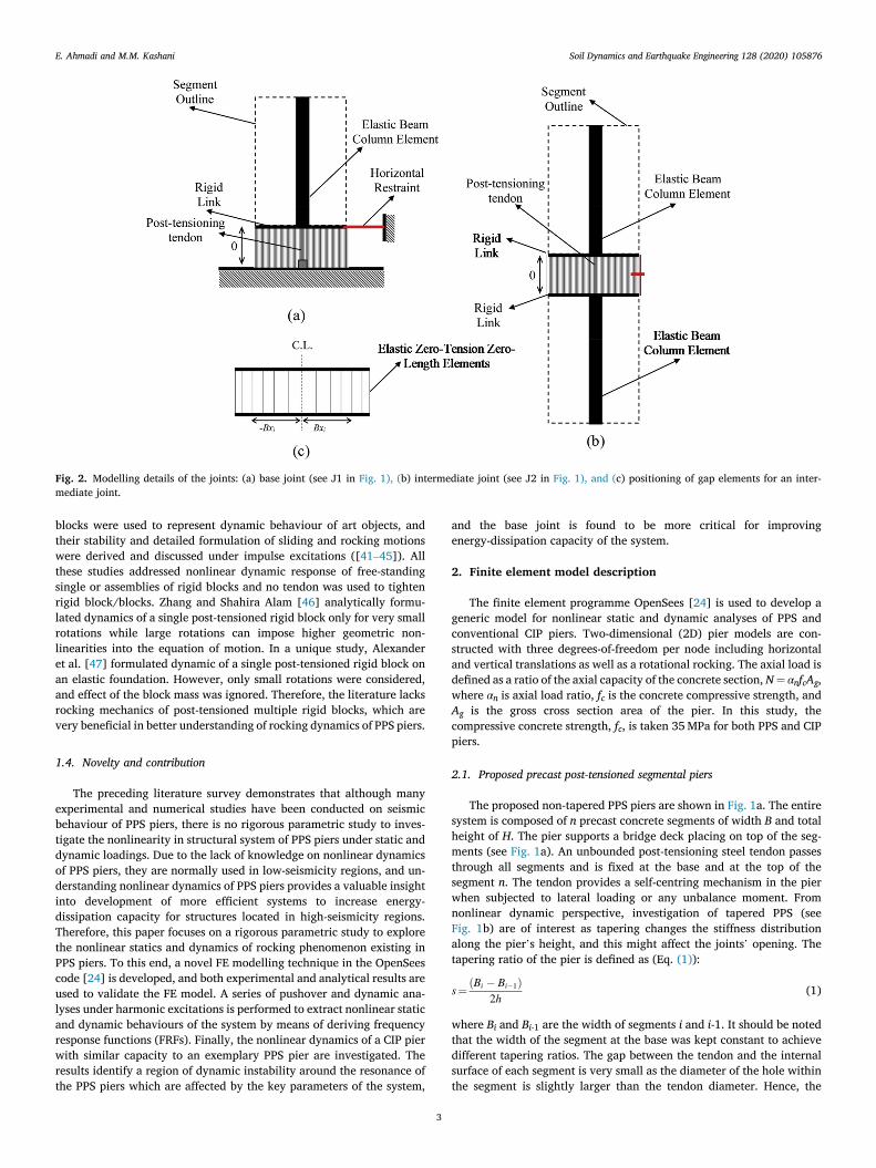
Fig. 2. Modelling details of the joints: (a) base joint (see J1 in Fig. 1), (b) intermediate joint (see J2 in Fig. 1), and (c) positioning of gap elements for an inter-mediate joint.
E. Ahmadi and M.M. Kashani

Soil Dynamics and Earthquake Engineering 128 (2020) 105876
4
segments are not allowed to slide on top of each other. Thus, the sliding between segments, and accordingly frictional damping is ignored in this study.
The segments are modelled using Elastic Beam-Column elements with bending rigidity, EcI (Ec and I are elastic modulus of the concrete and second moment of area of the segments section). The steel tendon is
modelled with a Truss Element. An Elastic Perfectly Plastic material is used to model the tendon. An initial strain was incorporated into the material model to account for the axial shortening due to post- tensioning force of the tendon. Yield stress, σy, and elastic modulus of the tendon were taken 1860 MPa and 200 GPa respectively. Corotational geometric transformation is used in Beam-Column and Truss elements to account for their geometric nonlinearities. The axial load due to the bridge deck was applied as a vertical force on the topmost node of the column. Apart from this, inertial effects of the bridge deck is considered by applying lumped horizontal and vertical masses to the top node of the piers. These masses are corresponding to the axial force acting on the pier.
2.2. Modelling rocking joints of PPS piers
The details of the rocking joints of PPS piers are shown in Fig. 2. Based on the experimental test results reported by other researchers ([15,16,48]), the joints between rocking segments are not fully rigid, and hence, the contact surface between rocking segments must be accurately modelled using an appropriate stiffness distribution. The Lobatto Quadrature integration scheme introduced by Spieth et al. [49] is employed to distribute the axial stiffness of the segments across the
Table 1 Positioning and weighting of gap elements (see Fig. 2c for further detail on the positioning of the gap elements).
No. of gap elements Abscissas (xi) Weights(wi)
4 �1 0.167 �0.447 0.833
8 �1 0.036 �0.872 0.211 �0.592 0.341 �0.209 0.413
12 �1 0.015 �0.945 0.092 �0.819 0.158 �0.633 0.213 �0.400 0.251 �0.137 0.271
Fig. 3. (a) CIP pier, (b) pier section, and (c) OpenSees modelling.
E. Ahmadi and M.M. Kashani

Soil Dynamics and Earthquake Engineering 128 (2020) 105876
5
contact surface of individual rocking joints. Each rocking joint is modelled as a series of vertical zero-length gap elements. An elastic zero-tension uniaxial material model is used for the joints to model joint opening and compression forces at the contact surfaces. The vertical stiffness of the ith gap element of each joint is determined using the Eq. (2) below:
ki¼wiEcAg
2LI(2)
where, Ec ¼ 4700ffiffiffiffifc
pis the elastic modulus of the concrete [50]; LI is the
influence length of the bottom-most segment for the base joint, roughly taken h1/2, and is the influence length of both top and bottom segments for the jth intermediate joints, approximately taken (hj-1 þ hj)/2 where hj-1 and hj are the heights of segment j-1 and j (validity of this assumption is investigated in Section 3.2); wi is the weight of the stiffness of each gap element, and was calculated from Lobatto Quadrature scheme as shown in Table 1.
Rigid links are used between adjacent top and bottom nodes of each joint to simulate rocking motion. Linear geometric transformation is used for rigid links. All degrees-of-freedom of the bottom node of the gap elements at the base joint are restrained to impose a fixed-base condition beneath the rocking joint. The horizontal degree-of-freedom of top node of the end gap element is also restrained to avoid sliding at the base (Fig. 2a). A horizontal zero-length gap element between top and bottom nodes of the end vertical gap element with an elastic uniaxial material of very large stiffness is used to allow for shear transfer at the intermediate joints (shown by red in Fig. 2b). Furthermore, to permit shear transfer between rigid links and adjacent segments, equal degree-of-freedom constraints were adopted (master-slave nodes in OpenSees as shown in Fig. 2b).
2.3. Proposed conventional cast-in-place RC pier
Fig. 3 illustrates the proposed CIP pier in this study. The CIP pier is modelled using a five-node Nonlinear Fibre Beam-Column element. Uniaxial Steel02 and Concrete02 are used to model the nonlinear behaviour of reinforcing steel and concrete, respectively. The pier sec-tion is modelled by a Fibre Section in OpenSees where the section is broken down into fibres and uniaxial materials are defined indepen-dently. Yield stress and elastic modulus of the reinforcing steel are 420 MPa and 200 GPa. Five layers of reinforcement are defined in cross section. P-Delta geometric transformation is assigned to the pier element
to account for the second order effect. All degrees of freedom at the bottom node are restrained to achieve a fixed-base condition. Horizontal and vertical masses at the top node of the piers are used to simulate the inertial effects of the bridge deck (similar to PPS piers). The axial force ratio is also taken identical to the PPS pier.
3. Model verification
3.1. Analytical verification for single tied rigid blocks with rigid contact surface
In this section, analytical moment-rotation relationship of a single tied rigid rocking block is first used to verify the OpenSees model of PPS piers. Consider a single tied rigid block of width B and height H rocking on a rigid surface around its edges. Taking a moment around the pivot point, using kinematic of rigid bodies, and applying the equilibrium rule, the static moment-rotation relationship for a single tied rigid block is defined in Equation. (3) [51]:
MðθÞ¼ λktB cos�θ
2
��
2λB sin�θ
2
�þ
T0
kt
�
� WR sinðβþ θÞ (3)
where λ is 0.5 for positive rocking, while for negative rocking λ is -0.5; kt is the elastic stiffness of the post-tensioning tendon, which is EsAs/H; T0 is the initial post-tensioning force of the tendon, and W is the total weight of the block. The clockwise rocking is taken positive, and the block angle, β, and rocking radius, R, are defined as follows:
β¼ � tan� 1�
2λBH
�
; R¼ffiffiffiffiffiffiffiffiffiffiffiffiffiffiffiffiffiffiffiffiffi
λ2B2 þH2
4
r
(4)
To achieve a rigid segment and a rigid base for the OpenSees model, the bending rigidity, EcI, of the segment, and axial stiffness of the gap elements (see equation (2)), are set to very large values. Fig. 4 compares the moment-rotation curves of a single tied rigid block determined from the OpenSees model and the analytical solution (equation (4)). The moment is normalized to the moment due to the gravitational force, i.e. total weight of the segment multiplied by the width of the segment, BW. As it is shown in Fig. 4, the curves are very similar, which verifies the OpenSees model. It should be noted that in Fig. 4b, the result of Open-Sees model deviates from the analytical solution at high rotation values, which is due to the yielding of post-tensioning tendon.
Fig. 4. Normalized static moment-rotation relationship for a single tied rigid segment on a rigid surface: (a) H/B ¼ 6, and (b) H/B ¼ 2.
E. Ahmadi and M.M. Kashani

Soil Dynamics and Earthquake Engineering 128 (2020) 105876
6
3.2. Experimental and analytical verification for post-tensioned multi- block columns with flexible contact surfaces
In this section, results of the experimental study and the reduced- order analytical model published in Ref. [16] are used to validate the OpenSees model in the current study. The experimental specimen is a post-tensioned multi–block column composed of 50 mm square wooden segments. The segments are tightened together by a 1 mm high-strength stainless steel cable. The elastic modulus of the wooden blocks and stainless steel cable are 12.5 GPa and 118 GPa respectively. To generate the inertia force of the top deck, a 2.5 kg lump mass is placed at the top of the column. The self-centring mechanism is provided by the cable with a 300 N post-tensioning force. Furthermore, the analytical model (described in detail in Ref. [16]) simulates the column as a single-degree-of-freedom (SDOF) systems based only on the base rota-tion. Fig. 5 compares base moment-rotation of the OpenSees model with that of the experimental specimen and analytical SDOF model for both
static and dynamic tests. The influence length is taken as the half of the total length of the segments for calculation of the contact stiffness at the joints in the OpenSees model. For the dynamic analysis of the OpenSees model, a constant stiffness-proportional Rayleigh damping of 3% is used for all elements of the model. As clearly seen in Fig. 5, the OpenSees model used in the current study can accurately capture both nonlinear static and dynamic behaviours of the post-tensioned segmental columns. Particularly, as seen in Fig. 5a, the proposed modelling approach reasonably replicates static stiffness of the post-tensioned segmental columns. It is worth mentioning that the influence length considered herein was verified for a specific geometry. However, the conclusions made in Section 4 will not be affected as a constant influence length is used in all analyses. For the dynamic modelling, a constant stiffness-proportional Rayleigh damping well simulates the damping of the post-tensioned segmental columns (see Fig. 5b). It should be noted that the damping in post-tensioned segmental columns mostly come from the behaviour of the joints between segments, and depends on the
Fig. 5. Normalized base moment-rotation relationship from OpenSees model, experimental specimen, and analytical model: (a) 9 blocks and static behaviour, and (b) 6 blocks and dynamic behaviour.
Fig. 6. PPS with n ¼ 6, αt ¼ 0.4, αn ¼ 0.1, and H/B ¼ 6 for various number of gap elements, ng: (a) pushover curves, and (b) tendon force ratio curves.
E. Ahmadi and M.M. Kashani

Soil Dynamics and Earthquake Engineering 128 (2020) 105876
7
level of ground motion amplitude [16], and hence, a combination of viscous and Coulomb damping is more suitable, and this may cause the difference between the OpenSees model and the experiment results.
4. Nonlinear analyses and discussion of results
In this section, a parametric study is performed to investigate the nonlinear static and dynamic behaviour of PPS piers. The static and dynamic analyses consist of defining and applying gravity loads, lateral static nodal load, and dynamic base excitation. The key parameters of the PPS piers, which may affect nonlinearity of the structural system are: (i) aspect ratio (height-to-width ratio, H/B), (ii) number of segments, n, (iii) axial load ratio, αn, and (iv) initial post-tensioning force of the tendon, T0. The pier’s height is set to 3 m, and the pier’s width is changed to investigate the influence of aspect ratio. To compare PPS and CIP piers, identical reinforcement ratio, ρ ¼As/Ag ¼ 0.02, is used for both piers, where, As is the cross-section area of the tendon in the PPS pier, and reinforcement area in the CIP pier.
4.1. Nonlinear static analysis (pushover)
For nonlinear static behaviour of the piers, pushover curves, i.e. base shear verses drift, for some exemplary cases are created and compared. In pushover analysis, the top node of the top-segment is taken as the controlling node, and a displacement-control analysis is used to monitor
the top displacement, Δ, versus base shear, V. The pier’s drift is defined as the lateral tip displacement normalized by the total height of the pier, Δ/H. The base shear coefficient is expressed as the base shear is normalized by the total weight of the pier (weight of the deck and col-umn together), V/W.
To reach an optimal number of gap elements for modelling rocking stiffness of contact surfaces i.e. joints between segments (see Section 2.2), pushover curves are plotted and compared for different number of gap elements, ns. Prior to each pushover analysis, a gravity analysis is performed to apply the gravity forces on the piers. Fig. 6a shows push-over curves for an exemplary PPS pier with various number of gap el-ements, and Fig. 6b shows the corresponding tendon force. For the exemplary pier in Fig. 6a, the initial post-tensioning force to yield force ratio of the tendon, αt ¼ T0/σy, is 0.4. As it is shown in Fig. 6a, for ns ¼ 4, the pushover result is far off the other pushover curves. As the number of gap elements increases, the resulting pushover curves and force ratio of the tendon approach their asymptotes. After careful examination of all cases, ns ¼ 12 was found to be the lowest number of gap elements which well approximates rocking stiffness of all joints. Note that in Fig. 6b, the tendon force ratio at the drift zero is less than 0.4. The drop in the initial tendon force ratio is because of the prestress loss due to elastic short-ening of the segments as well as the flexibility of rocking surfaces under gravity loads.
It should also be noted that the joints of PPS piers are close at very small displacements, and hence, an approximately linear behaviour is
Fig. 7. Effects of aspect ratio for the exemplary PPS (n ¼ 6, αt ¼ 0.4, αn ¼ 0.1): (a) pushover curves, (b) base moment-rotation curves, and (c) tendon force curves.
Fig. 8. Effects of axial force ratio for the exemplary PPS (n ¼ 6, αt ¼ 0.4, H/B ¼ 6): (a) pushover curves, (b) base moment-rotation curves, and (c) tendon force curves.
E. Ahmadi and M.M. Kashani
Soil Dynamics and Earthquake Engineering 128 (2020) 105876
8
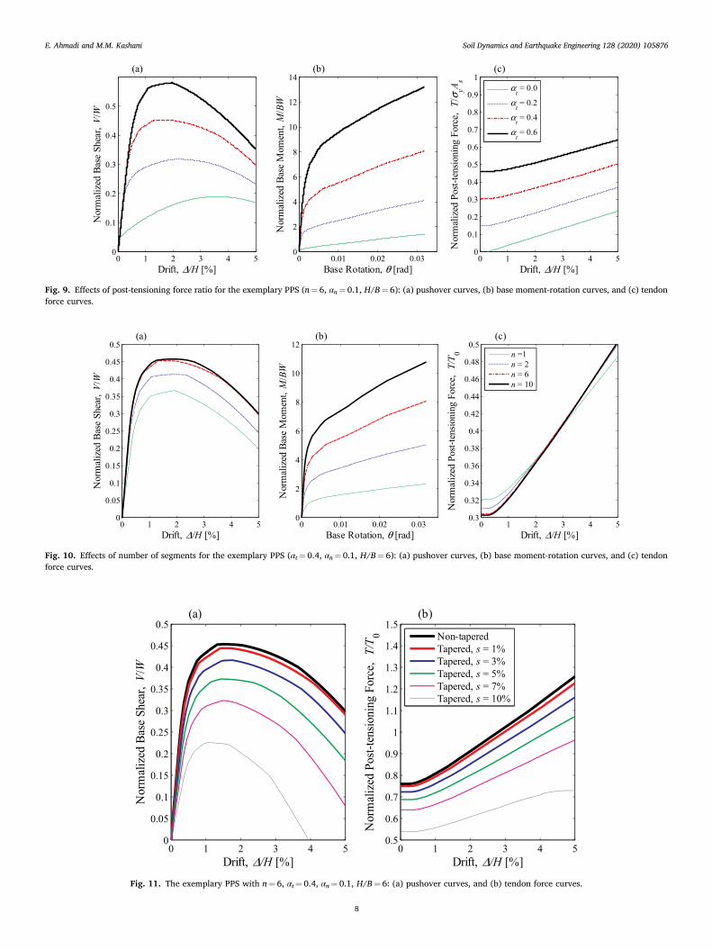
Fig. 9. Effects of post-tensioning force ratio for the exemplary PPS (n ¼ 6, αn ¼ 0.1, H/B ¼ 6): (a) pushover curves, (b) base moment-rotation curves, and (c) tendon force curves.
Fig. 10. Effects of number of segments for the exemplary PPS (αt ¼ 0.4, αn ¼ 0.1, H/B ¼ 6): (a) pushover curves, (b) base moment-rotation curves, and (c) tendon force curves.
Fig. 11. The exemplary PPS with n ¼ 6, αt ¼ 0.4, αn ¼ 0.1, H/B ¼ 6: (a) pushover curves, and (b) tendon force curves.
E. Ahmadi and M.M. Kashani
Soil Dynamics and Earthquake Engineering 128 (2020) 105876
9
achieved. This demonstrates beneficial effects of rocking for piers with higher number of segments. However, for post-opening phase of the joints, which occurs at higher displacements, the nonlinear behaviour of the pier is observed due to the geometric nonlinearity and tension stiffening of the cable. The pier’s stiffness decreases and the pier reaches a maximum base shear. After the peak, the pier’s stiffness becomes negative and further displacement gives lower base shear value.
Fig. 7 shows the effects of aspect ratio of the pier on the pushover curve, base moment-rotation curve, and tendon force. As seen, slender piers have lower stiffness, peak base shear and moment values, and tendon force ratios. On the contrary, squat piers have higher resisting gravity moments which improve stability of these piers. Furthermore, squat piers use much capacity of the tendon. While higher aspect ratio gives lower joint opening (see Fig. 7b), the larger lever arm of the tendon for squat piers provides higher deformation in the tendon, resulting in larger tendon force.
Fig. 8 investigates the effects of axial force ratio on pushover curve, base moment-rotation, and tendon force ratio. As seen, axial force ratio highly increases peak base shear and moment, and lowers tendon force ratio. This is because higher axial force ratio increases resisting moment
capacity of the system mostly for the pre-opening phase of the joints. However, the axial force ratio does not affect initial stiffness of the system. The effects of initial post-tensioning force of the tendon is illustrated in Fig. 9. The initial post-tensioning force does not affect initial stiffness of the pier. However, when the joints open, the tendon comes to play a key role in the pier’s stiffness, and higher initial post- tensioning force results in higher peak base shear and moment capac-ity of the pier. This well explains the tendon’s contribution to the self- centring capacity of the system. Further, after the joint opening, both axial force and post-tensioning force have similar effects and increase the stiffness of the system. The base moment-rotation diagram shows a hardening after the joint opening while the base shear-drift exhibits a softening due to second-order effects.
The effect of the number of segments is shown in Fig. 10. Higher number of segments slightly increases tendon force and initial stiffness of the PPS piers. For small drift values, as the rocking has not been started yet, the whole system acts approximately as an integral single- segment pier. However, after rocking of the segments at large drifts, the effect of number of segments becomes evident and larger peak base shear and moment values are achieved. However, it should be noted that the pushover and base moment-rotation curves are quite similar for n ¼ 6 and n ¼ 10. This means that an optimal number of segments exists above which no significant change is seen in the lateral stiffness, base shear and moment capacities of the PPS.
Fig. 11 compares pushover curves and tendon force ratios of non- tapered and tapered PPS piers with different tapering ratio, s. For all cases, tapering reduces peak base shear, initial stiffness, and tendon force ratio. Less tendon force ratio means lower amount of required tendon force from design perspective (see Fig. 11b). For tapering ratio s ¼ 3%, tapering has a negligible effect on initial stiffness and peak base shear values.
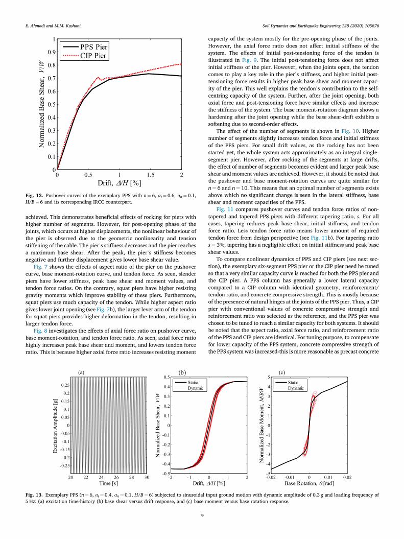
To compare nonlinear dynamics of PPS and CIP piers (see next sec-tion), the exemplary six-segment PPS pier or the CIP pier need be tuned so that a very similar capacity curve is reached for both the PPS pier and the CIP pier. A PPS column has generally a lower lateral capacity compared to a CIP column with identical geometry, reinforcement/ tendon ratio, and concrete compressive strength. This is mostly because of the presence of natural hinges at the joints of the PPS pier. Thus, a CIP pier with conventional values of concrete compressive strength and reinforcement ratio was selected as the reference, and the PPS pier was chosen to be tuned to reach a similar capacity for both systems. It should be noted that the aspect ratio, axial force ratio, and reinforcement ratio of the PPS and CIP piers are identical. For tuning purpose, to compensate for lower capacity of the PPS system, concrete compressive strength of the PPS system was increased-this is more reasonable as precast concrete
Fig. 12. Pushover curves of the exemplary PPS with n ¼ 6, αt ¼ 0.6, αn ¼ 0.1, H/B ¼ 6 and its corresponding IRCC counterpart.
Fig. 13. Exemplary PPS (n ¼ 6, αt ¼ 0.4, αn ¼ 0.1, H/B ¼ 6) subjected to sinusoidal input ground motion with dynamic amplitude of 0.3 g and loading frequency of 5 Hz: (a) excitation time-history (b) base shear versus drift response, and (c) base moment versus base rotation response.
E. Ahmadi and M.M. Kashani

Soil Dynamics and Earthquake Engineering 128 (2020) 105876
10
has normally more quality than cast-in-place concrete. Fig. 12 compares pushover curves of the PPS pier and its corresponding CIP pier. As it is shown in Fig. 12, both piers have similar stiffness in linear region at small lateral displacements. However, at large lateral displacements both systems experience nonlinear behaviour and the structural behaviour of the systems become different. Geometric nonlinearities is the source of nonlinear behaviour of the PPS pier, but in contrast, ma-terial nonlinearities such as reinforcement yielding, and concrete cracking/crushing is the source of nonlinearity in the CIP pier.
4.2. Nonlinear dynamic analysis
For nonlinear dynamic analyses, sinusoidal dynamic response and frequency response functions (FRFs) of the piers are determined and compared. As discussed in Section 3.2, a constant stiffness-proportional
Rayleigh damping model was found suitable for the PPS piers. The conventional damping value of 5% is considered for all elements in the models. Fig. 13 compares normalized dynamic base shear-drift and normalized moment-rotation versus static results for a sinusoidal exci-tation of amplitude 0.3 g (g is gravitational acceleration) and frequency 5 Hz. The narrow hysteresis behaviour confirms low energy dissipation capacity of the PPS pier as noted in the introduction. The results of analyses for other values of damping (3% and 7%) showed that the structural response such as maximum drift and base shear are not sen-sitive to the value of the damping used in the nonlinear dynamic analyses.
For structural engineering applications, FRFs are usually created from stepped sine-sweep, (more accurately known as sine-dwell) input base excitation. Sine-dwell analysis is the discrete form of continuous sine-sweep analysis. The input loading frequency is changed by a
Fig. 14. Exemplary PPS response (n ¼ 6, αt ¼ 0.4, αn ¼ 0.1, H/B ¼ 6) subjected to sine-dwell input ground motion with dynamic amplitude of 0.06g: (a) full ac-celeration response time-history, (b) isolated steady-state acceleration response, and (c) conversion of time domain to frequency domain.
Fig. 15. FRFs and backbone curves of exemplary PPS (αt ¼ 0.4, αn ¼ 0.1, H/B ¼ 6) with different number of segments: (a) n ¼ 1, (b) n ¼ 2, (c) n ¼ 6, and (d) n ¼ 10.
E. Ahmadi and M.M. Kashani

Soil Dynamics and Earthquake Engineering 128 (2020) 105876
11
discrete increment not continuously, and the structure is given enough time to each a steady-state response. A MATLAB [52] algorithm is developed, which generates the sine-dwell input excitation, and con-verts the time-history response to FRFs in frequency domain. Further-more, as the response of nonlinear systems is unstable at their resonant frequency, it might comprise lower and upper branches at high ampli-tudes of vibration. Therefore, increasing and decreasing frequency
sine-sweep analyses are used to capture possible lower and upper branches of FRFs. For the upper-branch response, a high-amplitude impulse is applied to the piers prior to using the sine-sweep analysis with decreasing frequency. This impulse alters the initial condition of the nonlinear PPS and results in overlapping dynamic response.
Fig. 14 illustrates the three-step procedure used to extract FRFs of the piers for an exemplary PPS for excitation amplitude of 0.06g: (1) for each
Fig. 16. FRFs of exemplary PPS (αn ¼ 0.1, n ¼ 6) for different: (a) aspect ratios, H/B, and dynamic amplitude, 0.005 g, (b) aspect ratios, H/B, and dynamic amplitude, 0.2 g, (c) post-tensioning force ratio, αt, and dynamic amplitude, 0.005 g, and (d) post-tensioning force ratio, αt, and dynamic amplitude, 0.2 g.
Fig. 17. Response distribution over structural joints of an exemplary PPS (n ¼ 6, αt ¼ 0.4, αn ¼ 0.1, H/B ¼ 6) subjected to sine-dwell input ground motion with dynamic amplitudes of 0.1 g, 0.2 g, and 0.3g with frequency around resonance: (a) lateral displacement, (b) absolute rotation, and (c) relative rotation.
E. Ahmadi and M.M. Kashani

Soil Dynamics and Earthquake Engineering 128 (2020) 105876
12
loading frequency, the dynamic analysis was performed for 50 s, and acceleration time history of the top node of the pier was determined (see Fig. 14a), (2) the transient part of the response was removed for each loading frequency at the time domain (see Fig. 14b), and (3) the isolated steady-state response was plotted versus the loading frequencies for lower and upper branches of the response (see Fig. 13c).
In this study, the FRFs are created for frequencies around the fre-quency of first natural mode of vibration of the piers. The first mode natural frequencies of the PPS piers are in range of 2–3 Hz. The second mode natural frequencies are in range of 20–30 Hz. At very low ampli-tudes of dynamic loading (e.g. 0.0001g), the rocking joints of PPS piers are still close, i.e. pre-opening phase. Hence, the system behaves line-arly, and excitation frequencies corresponding to FRFs’ peaks (resonant frequencies) are approximately similar to natural frequencies of the system, fn calculated using modal/eigenvalue analysis. Backbone curves are also determined using FRFs’ peaks at different excitation amplitudes and shown in Fig. 15.
Fig. 15 shows the FRFs and backbones curves of exemplary piers with one, two, six, and ten segments. The excitation amplitude is varied from 0.0001 g to 0.3 g. For the exemplary PPS shown in Fig. 15, the first resonant frequencies are 2.4 Hz, 2.8 Hz, 3.0 Hz, and 3.0 Hz for n ¼ 1, n ¼ 2, n ¼ 6, and n ¼ 10 respectively. The natural frequencies, fn,
determined from eigenvalue analysis of the FE models are 2.42 Hz, 2.80 Hz, 2.94 Hz, and 2.96 Hz. As the number of segments increases, the pier’s natural frequency becomes slightly larger. As it is shown in Fig. 15, the unstable region, where the solution does not converge in the FE model, becomes wider around the resonant frequency with higher number of segments. Sub-harmonic resonances of the system are also observed at the lower branch of the response for high-amplitude exci-tations. This demonstrates the importance of subharmonics at high excitation amplitudes for PPS piers.
Fig. 16 shows the effects of aspect ratio of the PPS pier and post- tensioning force ratio of the tendon on the FRFs for very low and high excitation amplitudes. Squat piers give smaller vibration response, and slenderising the pier makes the solution more unstable about the reso-nant frequency (see Fig. 16a–b). Increasing the post-tensioning force of the pier, however, improves convergence of the solution around the resonance as instability was observed in the solutions for αt ¼ 0 and αt ¼ 0.2. Further, the post-tensioning force ratio does not affect the natural frequency of the system, and lowers dynamic response of the system.
Figs. 17 and 18 show the structural response distribution of an exemplary PPS pier over the system’s joints under a sinusoidal loading with an excitation frequency around resonant frequency of the system.
Fig. 18. Response distribution over structural joints of an exemplary PPS (n ¼ 6, αt ¼ 0.4, αn ¼ 0.1, H/B ¼ 6) subjected to sine-dwell input ground motion with dynamic amplitudes of 0.1 g, 0.2 g, and 0.3 g with frequency around resonance: (a) acceleration, (b) normalized shear force, and (c) normalized moment.
Fig. 19. FRFs of exemplary PPS with n ¼ 6, αt ¼ 0.4, αn ¼ 0.1, H/B ¼ 6: (a) 0.005 excitation amplitude, and (b) 0.1 g excitation amplitude (lower branch only).
E. Ahmadi and M.M. Kashani

Soil Dynamics and Earthquake Engineering 128 (2020) 105876
13
The responses at a specific time instant are extracted. First of all, all responses follow the first mode shape of the system as they have iden-tical phase for the specific time instant, i.e. positive response values. The displacement demand of the joints has an increasing variation identical to a cantilever continuous pier (see Fig. 17a). The absolute rotation of the joints, θ, increases too as the rocking of bottom segments adds to the rotation of each segment (see Fig. 17b). However, the relative rotation, ϴ, (i.e. absolute rotation of the bottom joint subtracted from absolute rotation of the joint), reduces (see Fig. 17c). This demonstrates that the bottom segment and joint have the highest effect on rocking of the system.
The acceleration response also increases up to the joint five and then decreases (see Fig. 18a). However, comparing the magnitude of accel-eration responses to those from FRFs of the top node (see Fig. 15c) shows that the deck experiences smaller accelerations compared to its below segment due to inertial effects of the top deck. Fig. 18b and c clearly indicate that the base joint has the highest shear and moment values compared to the upper joints.
The nonlinear dynamic analysis of the tapered PPS piers showed that the solution becomes more unstable around the resonant frequency, and at higher amplitude of loading particularly for upper branch of the so-lution (the FE model did not converge). Therefore, Fig. 19 compares only lower-branch FRFs of tapered and non-tapered PPS piers for loading amplitude of 0005 g and 0.1 g. The natural frequencies deter-mined from eigenvalue analysis are 2.86 Hz, 2.68 Hz, and 2.48 Hz for tapering ratio of 1%, 3%, and 5%, respectively. The natural frequencies drop with increasing tapering ratio due to the reduction in stiffness of the system.
The natural frequencies of the PPS and CIP piers determined from eigenvalue analysis are 3.12 Hz and 3.05 Hz which are very close. Fig. 20 compares nonlinear dynamics of the exemplary PPS pier and its corresponding CIP pier for the case shown in Fig. 12 for excitation amplitude of 0.3 g. A sudden increase is seen between 1.3 Hz and 1.4 Hz and then the response continuously increases until it reaches 2.1 Hz. Further, unlike the PPS where an instability region is seen around the resonance, the CIP pier does not exhibit any non-convergence in the solution (see Fig. 20a). This demonstrates the lower probability of observing lower/upper amplitude of responses in CIP compared to PPS piers. The PPS pier shows higher acceleration response around the resonance (upper branch). The hysteretic response of the CIP is much wider than that of the PPS which indicates higher energy-dissipation
capacity of the CIP pier arising from irreversible material nonlinearity (see Fig. 20b). On the contrary, the residual drift of the CIP pier is far larger than the PPS pier, and the PPS pier shows lower drift ratio and base shear compared to the CIP pier.
5. Conclusions
In this work, the complex nonlinear mechanics and dynamics of PPS piers are explored using a novel FE modelling technique in the OpenSees code. 2D tapered and non-tapered PPS piers are statically and dynami-cally analysed and the influence of key parameters is investigated. A conventional CIP pier is also analysed, and compared to its corre-sponding PPS counterpart.
The results of pushover analyses showed that higher axial load ratio, post-tensioning force ratio, and number of segments increase the lateral load strength of the system. The tapered PPS piers have lower lateral force strength compared to their corresponding non-tapered ones. However, lower force in the tendon is also observed, which indicates a trade-off between tapering ratio and tendon force for design purposes.
The results of dynamic analyses demonstrated a convergence insta-bility for the solution around the resonant frequency, and accordingly lower/upper responses. This dynamic phenomenon becomes more pro-nounce as the number of segments, tapering ratio, and aspect ratio in-crease, and the post-tensioning force reduces. The dynamic response distribution around the first resonance over structural joints followed the first mode shape of a cantilever continuous pier. The maximum shear, moment, and rotation were observed at the base joint. This im-plies that any energy-dissipating method is highly efficient if used to mitigate dynamic response at the bottom joints of PPS piers.
Comparing an exemplary PPS pier with its CIP counterpart pier showed that the PPS pier gives lower drift and residual deformation as well as higher acceleration at the top of the pier. The PPS pier also has lower energy-dissipation capacity, and a strategy to increase damping level of the system while reducing rocking motion of the segments are of great interest.
Acknowledgement
The first author acknowledges support received by the UK Engi-neering and Physical Sciences Research Council (EPSRC) for a Pros-perous Nation [grant number EP/R039178/1]: SPINE: Resilience-Based
Fig. 20. Dynamic analysis results of the exemplary PPS with n ¼ 6, αt ¼ 0.6, αn ¼ 0.1, H/B ¼ 6 and its corresponding IRCC counterpart: (a) FRF, and (b) normalized base shear-drift curves.
E. Ahmadi and M.M. Kashani

Soil Dynamics and Earthquake Engineering 128 (2020) 105876
14
Design of Biologically Inspired Columns for Next-Generation Acceler-ated Bridge Construction].
Appendix A. Supplementary data
Supplementary data to this article can be found online at https://doi. org/10.1016/j.soildyn.2019.105876.
References
[1] Shim CS, Chung CH, Kim HH. Experimental evaluation of seismic performance of precast segmental bridge piers with a circular solid section. Eng Struct 2008;30: 3782–92. https://doi.org/10.1016/j.engstruct.2008.07.005.
[2] Dawood H, ElGawady M, Hewes J. Behavior of segmental precast posttensioned bridge piers under lateral loads. J Bridge Eng 2012;17:735–46. https://doi.org/ 10.1061/(ASCE)BE.1943-5592.0000252.
[3] Tazarv M, Saiid Saiidi M. Low-damage precast columns for accelerated bridge construction in high seismic zones. J Bridge Eng 2016;21:4015056. https://doi. org/10.1061/(ASCE)BE.1943-5592.0000806.
[4] Haber ZB. Precast column-footing connections for accelerated bridge construction in seismic zones. In: ProQuest Dissertations and Theses; 2013. p. 661.
[5] Billington SL, Barnes RW, Breen JE. Precast segmental substructure system for standard bridges. Precast Concr Inst J 1999:56–73. https://doi.org/10.15554/ pcij.07011999.56.73.
[6] Hewes JT. Seismic design and performance of precast concrete segmental bridge columns. 2002. https://doi.org/10.1016/S0165-0327(00)00241-X.
[7] Ou Y-C, Chiewanichakorn M, Aref AJ, Lee GC. Seismic performance of segmental precast unbonded posttensioned concrete bridge columns. J Struct Eng 2007;133: 1636–47. https://doi.org/10.1061/(ASCE)0733-9445(2007)133:11(1636).
[8] Chou CC, Chen YC. Cyclic tests of post-tensioned precast CFT segmental bridge columns with unbonded strands. Earthq Eng Struct Dyn 2006;35:159–75. https:// doi.org/10.1002/eqe.512.
[9] Marriott D, Pampanin S, Palermo A. Quasi-static and pseudo-dynamic testing of unbonded post-tensioned rocking bridge piers with external replaceable dissipaters. Earthq Eng Struct Dyn 2009;38:331–54. https://doi.org/10.1002/ eqe.857.
[10] ElGawady MA, Sha’lan A. Seismic behavior of self-centering precast segmental bridge bents. J Bridge Eng 2011;16:328–39. https://doi.org/10.1061/(ASCE) BE.1943-5592.0000174.
[11] Ou YC, Sen Tsai M, Chang KC, Lee GC. Cyclic behavior of precast segmental concrete bridge columns with high performance or conventional steel reinforcing bars as energy dissipation bars. Earthq Eng Struct Dyn 2010;39:1181–98. https:// doi.org/10.1002/eqe.986.
[12] Motaref S, Saiidi M, Sanders D. Experimental study of precast bridge columns with built-in elastomer. Transp Res Re.: J Transp Res Board 2010;2202:109–16. https:// doi.org/10.3141/2202-14.
[13] Sideris P, Aref AJ, Filiatrault A. Large-scale seismic testing of a hybrid sliding- rocking posttensioned segmental bridge system. J Struct Eng 2014;140:4014025. https://doi.org/10.1061/(ASCE)ST.1943-541X.0000961.
[14] Sideris P, Aref AJ, Filiatrault A. Experimental seismic performance of a hybrid sliding – rocking bridge for various specimen configurations and seismic loading conditions. J Bridge Eng 2015;20:1–15. https://doi.org/10.1061/(ASCE)BE.1943- 5592.0000742.
[15] Kashani MM, Gonzalez-Buelga A. Nonlinear dynamics of self-centring segmental composite rocking column. Procedia Eng. 2017;199:441–6. https://doi.org/ 10.1016/j.proeng.2017.09.176.
[16] Kashani MM, Gonzalez-Buelga A, Thayalan RP, Thomas AR, Alexander NA. Experimental investigation of a novel class of self-centring spinal rocking column. J Sound Vib 2018;437:308–24. https://doi.org/10.1016/j.jsv.2018.08.034.
[17] Kashani MM, Ahmadi E, Gonzalez-Buelga A, Zhang D, Scarpa F. Layered composite entangled wire materials blocks as pre-tensioned vertebral rocking columns. Compos Struct 2019;214:153–63. https://doi.org/10.1016/j. compstruct.2019.02.021.
[18] Ahmadi E, Kahshani MM. On the use of entangled wire materials in pre-tensioned rocking columns. J Phys Conf Ser 2019;1264:012007. https://doi.org/10.1088/ 1742-6596/1264/1/012007.
[19] Motaref S. Seismic response of precast bridge columns with energy dissipating joints. 2011.
[20] Zhang N. Dynamic properties and application of steel fiber reinforced self- consolidating concrete to segmental bridge columns in moderate-to-high seismic regions. 2014.
[21] Lee WK, Billington SL. Modeling residual displacements of concrete bridge columns under earthquake loads using fiber elements. J Bridge Eng 2010;15:240–9. https:// doi.org/10.1061/(ASCE)BE.1943-5592.0000059.
[22] Abdel Raheem SE. Pounding mitigation and unseating prevention at expansion joints of isolated multi-span bridges. Eng Struct 2009;31:2345–56. https://doi.org/ 10.1016/j.engstruct.2009.05.010.
[23] Shrestha B, Hao H, Bi K. Effectiveness of using rubber bumper and restrainer on mitigating pounding and unseating damage of bridge structures subjected to spatially varying ground motions. Eng Struct 2014;79:195–210. https://doi.org/ 10.1016/j.engstruct.2014.08.020.
[24] McKenna F. OpenSees: a framework for earthquake engineering simulation. Comput Sci Eng 2011;13:58–66. https://doi.org/10.1109/MCSE.2011.66.
[25] Cai Z-K, Zhou Z, Wang Z. Influencing factors of residual drifts of precast segmental bridge columns with energy dissipation bars. Adv Struct Eng 2019;22:126–40. https://doi.org/10.1177/1369433218780545.
[26] Spanos BPD, Koh A. Rocking of rigid blocks due to harmonic shaking. ASCE. J Eng Mech 1985;110:1627–42.
[27] Spanos PD, Koh AS. Analysis of block random rocking. Soil Dyn Earthq Eng 1986;5: 178–83. https://doi.org/10.1016/0267-7261(86)90021-7.
[28] Shenton HW, Jones NP. Base excitation of rigid bodies. I: formulation. J Eng Mech 1991;117:2286–306. https://doi.org/10.1061/(ASCE)0733-9399(1991)117:10 (2286).
[29] Shenton HW, Jones NP. Base excitation of rigid bodies. II: periodic slide-rock response. J Eng Mech 1991;117:2307–28. https://doi.org/10.1061/(ASCE)0733- 9399(1991)117:10(2307).
[30] Kounadis AN. Parametric study in rocking instability of a rigid block under harmonic ground pulse: a unified approach. Soil Dyn Earthq Eng 2013;45:125–43. https://doi.org/10.1016/j.soildyn.2012.10.002.
[31] Dimitrakopoulos EG, DeJong MJ. Revisiting the rocking block: closed-form solutions and similarity laws. Proc R Soc A Math Phys Eng Sci 2012;468:2294–318. https://doi.org/10.1098/rspa.2012.0026.
[32] Yim C-S, Chopra AK, Penzien J. Rocking response of rigid blocks to earthquakes. Earthq Eng Struct Dyn 1980;8:565–87. https://doi.org/10.1002/eqe.4290080606.
[33] Aslam M, Godden WG, Scalise DT. Earthquake rocking response of rigid bodies. J Struct Div 1980;106:377–92.
[34] Pompei A, Scalia A, Sumbatyan MA. Dynamics of rigid block due to horizontal ground motion. J Eng Mech 1998;124:713–7. https://doi.org/10.1061/(asce) 0733-9399(1998)124:7(713).
[35] DeJong MJ, Dimitrakopoulos EG. Dynamically equivalent rocking structures. Earthq Eng Struct Dyn 2014;43:1543–63. https://doi.org/10.1002/eqe.2410.
[36] de Leo AM, Simoneschi G, Fabrizio C, Di Egidio A. On the use of a pendulum as mass damper to control the rocking motion of a rigid block with fixed characteristics. Meccanica 2016;51:2727–40. https://doi.org/10.1007/s11012- 016-0448-5.
[37] Simoneschi G, de Leo AM, Di Egidio A. Effectiveness of oscillating mass damper system in the protection of rigid blocks under impulsive excitation. Eng Struct 2017;137:285–95. https://doi.org/10.1016/j.engstruct.2017.01.069.
[38] Simoneschi G, Geniola A, de Leo AM, Di Egidio A. On the seismic performances of rigid block-like structures coupled with an oscillating mass working as a TMD. Earthq Eng Struct Dyn 2017;46:1453–69. https://doi.org/10.1002/eqe.2864.
[39] Konstantinidis D, Makris N. Experimental and analytical studies on the seismic response of freestanding and restrained laboratory equipment. In: 8th US National Conference on earthquake engineering 2006. vol. 12; 2006. p. 7018–27.
[40] Palmeri A, Makris N. Response analysis of rigid structures rocking on viscoelastic foundation. Earthq Eng Struct Dyn 2008;37:1039–63. https://doi.org/10.1002/ eqe.800.
[41] Kounadis AN. On the rocking-sliding instability of rigid blocks under ground excitation: some new findings. Soil Dyn Earthq Eng 2015;75:246–58. https://doi. org/10.1016/j.soildyn.2015.03.026.
[42] Kounadis AN, Papadopoulos GJ. On the rocking instability of a three-rigid block system under ground excitation. Arch Appl Mech 2016;86:957–77. https://doi. org/10.1007/s00419-015-1073-9.
[43] Kounadis AN. The effect of sliding on the rocking instability of multi- rigid block assemblies under ground motion. Soil Dyn Earthq Eng 2018;104:1–14. https://doi. org/10.1016/j.soildyn.2017.03.035.
[44] Makris N, Vassiliou MF. The dynamics of the rocking frame. In: Computational Methods in Applied Sciences. 37; 2015. p. 37–59. https://doi.org/10.1007/978-3- 319-16130-3-2.
[45] Kounadis AN. Seismic instability of free-standing statues atop multispondyle columns: a heuristic very stable system of ancient technology. Soil Dyn Earthq Eng 2019;119:253–64. https://doi.org/10.1016/j.soildyn.2018.11.008.
[46] Zhang Q, Alam MS. The dynamics of precast post-tensioned rocking columns. 2018. p. 349–58. https://doi.org/10.1061/9780784481332.031.
[47] Alexander NA, Oddbjornsson O, Taylor CA, Osinga HM, Kelly DE. Exploring the dynamics of a class of post-tensioned, moment resisting frames. J Sound Vib 2011; 330:3710–28. https://doi.org/10.1016/j.jsv.2011.02.016.
[48] Kibriya LT, M�alaga-Chuquitaype C, Kashani MM, Alexander NA. Nonlinear dynamics of self-centring rocking steel frames using finite element models. Soil Dyn Earthq Eng 2018;115:826–37. https://doi.org/10.1016/j. soildyn.2018.09.036.
[49] Spieth HA, Carr AJ, Murahidy AG, Arnolds D, Davies M, Mander JB. Modelling of post-tensioned precast reinforced concrete frame structures with rocking beam- column connections. In: New Zealand society of earthquake engineering Conference 2004; 2004.
[50] Suksawang N, Wtaife S, Alsabbagh A. Evaluation of elastic modulus of fiber- reinforced concrete. ACI Mater J 2018;115:239–49. https://doi.org/10.14359/ 51701920.
[51] Ahmadi E, Kahshani MM. Nonlinear rocking dynamics of pre-tensioned single rigid blocks under harmonic base excitation. J Phys Conf Ser 2019;1265:012006. https://doi.org/10.1088/1742-6596/1264/1/012006.
[52] MATLAB R2017b. MATLAB (R2017b). The MathWorks Inc; 2017.
E. Ahmadi and M.M. Kashani