NUMERICAL AND EXPERIMENTAL INVESTIGATION OF LASER BEAM WELDING OF
13
Advances in Production Engineering & Management 3 (2008) 2, 93-105 ISSN 1854-6250 Original scientific paper 93 NUMERICAL AND EXPERIMENTAL INVESTIGATION OF LASER BEAM WELDING OF AISI 304 STAINLESS STEEL SHEET Balasubramanian, K.R. *; Siva Shanmugam, N. *; Buvanashekaran, G. ** & Sankaranarayanasamy, K. * *Department of Mechanical Engineering, National Institute of Technology, Tiruchirappalli – 620 015, Tamil Nadu, India. **Welding Research Institute, BHEL, Tiruchirappalli - 622 014, Tamil Nadu, India. Email: [email protected] Abstract: Laser welding offers the advantage of very low heat input to the weld, resulting in low distortion and the ability to weld heat sensitive components. To obtain good weld bead geometry the selection of input parameters is very important. Laser beam welding trials are carried-out for 1.6 mm thick austenitic stainless steel for different beam power, welding speed and beam angle. The experimental trials for butt-joint configuration are conducted based on three level Box-Behnken design with replication resulting in 15 trials. The transient temperature profiles and weld pool dimensions, depth of penetration (DP) and bead width (BW) of the weld have been calculated using finite element code SYSWELD. A three dimensional Conical Gaussian heat source and the temperature dependent thermo-physical properties of AISI 304 stainless steel sheet are employed for performing a non-linear transient thermal analysis. It is found that the optimized parameters for deep penetration welding are laser power of 1250 Watts, welding speed of 750 mm/min and beam angle of 90º. Finally, the results of the simulation models and the experimental results are compared. Key Words: Finite element model (FEM), Laser beam welding, austenitic stainless steel, thermal analysis, 3D Conical Gaussian heat source 1. INTRODUCTION AND REVIEW In industrial manufacturing high power density welding technologies, such as laser welding is being increasingly utilized. Laser welding process offers great potential for the new product design. Laser welding has some attractive features such as high weld strength to weld size ratio, reliability, and minimal heat affected zone (HAZ), which is suitable for welding of heat sensitive materials. The beneficial characteristics of laser welding are low distortion due to heat, noncontact process, repeatability, ability to automate and high throughput. Recently a wide range of research activity has been undertaken in the area of laser beam delivery systems, mechanical behaviour of laser welded austenitic stainless steel sheets, finite element analysis of melt pool to estimate the fusion zone, heat affected zone and residual stresses. When developing the welding procedure for a specific application, each of these parameters must be characterized and fully specified. During laser welding, complicated phenomena such as temperature dependency of material properties during phase transition (i.e. melting and evaporation) and laser light absorption and reflection in plasma occur in a very short time. As the mechanical properties of a weld are highly dependent on the cooling rate of the weld metal, knowledge of the temperature field in and around the melt pool is essential for modeling of the welding process. Many models were proposed for laser welding to produce reliable predictions of temperature distributions that are of great importance for in-depth analysis and eventual
Transcript of NUMERICAL AND EXPERIMENTAL INVESTIGATION OF LASER BEAM WELDING OF

Advances in Production Engineering & Management 3 (2008) 2, 93-105 ISSN 1854-6250 Original scientific paper
93
NUMERICAL AND EXPERIMENTAL INVESTIGATION OF LASER BEAM WELDING OF AISI 304 STAINLESS STEEL
SHEET
Balasubramanian, K.R. *; Siva Shanmugam, N. *; Buvanashekaran, G. ** & Sankaranarayanasamy, K. *
*Department of Mechanical Engineering, National Institute of Technology, Tiruchirappalli – 620 015, Tamil Nadu, India.
**Welding Research Institute, BHEL, Tiruchirappalli - 622 014, Tamil Nadu, India. Email: [email protected]
Abstract: Laser welding offers the advantage of very low heat input to the weld, resulting in low distortion and the ability to weld heat sensitive components. To obtain good weld bead geometry the selection of input parameters is very important. Laser beam welding trials are carried-out for 1.6 mm thick austenitic stainless steel for different beam power, welding speed and beam angle. The experimental trials for butt-joint configuration are conducted based on three level Box-Behnken design with replication resulting in 15 trials. The transient temperature profiles and weld pool dimensions, depth of penetration (DP) and bead width (BW) of the weld have been calculated using finite element code SYSWELD. A three dimensional Conical Gaussian heat source and the temperature dependent thermo-physical properties of AISI 304 stainless steel sheet are employed for performing a non-linear transient thermal analysis. It is found that the optimized parameters for deep penetration welding are laser power of 1250 Watts, welding speed of 750 mm/min and beam angle of 90º. Finally, the results of the simulation models and the experimental results are compared. Key Words: Finite element model (FEM), Laser beam welding, austenitic stainless steel, thermal analysis, 3D Conical Gaussian heat source 1. INTRODUCTION AND REVIEW In industrial manufacturing high power density welding technologies, such as laser welding is being increasingly utilized. Laser welding process offers great potential for the new product design. Laser welding has some attractive features such as high weld strength to weld size ratio, reliability, and minimal heat affected zone (HAZ), which is suitable for welding of heat sensitive materials. The beneficial characteristics of laser welding are low distortion due to heat, noncontact process, repeatability, ability to automate and high throughput. Recently a wide range of research activity has been undertaken in the area of laser beam delivery systems, mechanical behaviour of laser welded austenitic stainless steel sheets, finite element analysis of melt pool to estimate the fusion zone, heat affected zone and residual stresses. When developing the welding procedure for a specific application, each of these parameters must be characterized and fully specified. During laser welding, complicated phenomena such as temperature dependency of material properties during phase transition (i.e. melting and evaporation) and laser light absorption and reflection in plasma occur in a very short time. As the mechanical properties of a weld are highly dependent on the cooling rate of the weld metal, knowledge of the temperature field in and around the melt pool is essential for modeling of the welding process.
Many models were proposed for laser welding to produce reliable predictions of temperature distributions that are of great importance for in-depth analysis and eventual

Balasubramanian, Shanmugam, Buvanashekaran: Numerical and Experimental Investigation of … improvement of process. Mazumder and Steen [1] developed the first numerical model of the continuous laser welding process. This model implemented the finite difference technique for a Gaussian beam intensity distribution and started with the assumption that the absorptivity of the incident radiation below the boiling point was 20%. While the convective flow in the weld pool and the temperature dependence of thermophysical properties were not considered, the non linearities of convection and radiation to surroundings were included in the model. The absorptivity of laser radiation was considered to be 100% when the temperature exceeded the boiling point. Goldak et al. [2] introduced a double ellipsoidal type of representation of the welding arc in the context of fusion arc welding and also showed its suitability for modeling high penetration welding. Frewin and Scott [3] proposed a three dimensional finite element analysis for pulsed laser welding. From experiments they found the heat flux distribution to be conical. The measured longitudinal power density distribution within the beam, as a function of distance from the focused spot, revealed the influence of the position of the focal point on the final weld bead dimensions. A De et al. [4] studied the heat transfer analysis following the double ellipsoidal representation of the laser beam, which incorporates volumetric heat input from a heat source. The temperature dependence of material properties, phase change phenomena, and convective and radiative heat losses from all the surfaces of a sheet are considered. Numerical simulation of the welding process presented by S.A.Tsirkas et al. [5] explained the physical essence of some complex phenomena and also used for optimizing the welding parameters. W.S..Chang and S.J. Na [6] employed combined model of finite element analysis and Neural Network for the prediction of laser spot weld bead shapes for sheet with gap. The Weld bead dimensions produced by laser welding depends on various parameters such as beam power, welding speed, beam angle gas flow rate, focal length and spot diameter [7]. Among these, the influence of gas flow rate on bead dimensions is less and is essential for shielding the weld pool to avoid the atmospheric contamination during welding [8]. The above brief review indicates that the form of the representation used for the laser beam has a significant effect on the results of numerical models of the laser beam welding process. A Gaussian representation of the laser beam, assuming heat input only on the top surface of the material may not lead to correct results, especially for high power lasers that penetrate rapidly through some distance into the material thickness, resulting in welds of high depth to width ratio and small heat affected zone. Due to these advantages it is used in several industries, including automotive, electronics, medical instruments, home appliances, food industries and specialized tube industry. AISI 304 stainless steel is a superior absorber of laser light. Consequently, slightly higher weld penetration depths can be achieved than with that of the carbon steel for the given condition.
In order to have a better understanding of Laser welding process and establish the knowledge base to support this process, the physical phenomena should be studied by finite element simulation. In this paper, numerical analysis of the laser welding of austenitic stainless steel is conducted to provide guidelines for optimizing the process parameter. The application of the model is verified with experimental investigation (butt joint configuration) and the results are in good concurrence. 2. FINITE ELEMENT ANALYSIS The laser welding process is characterized by the highly collimated and concentrated beam energy. This process makes it difficult to provide an accurate measurement of temperature, fusion zone and heat affected zone. It is very difficult to provide an accurate measurement of temperature distribution, fusion zone and HAZ, since the beam power is highly concentrated. Hence finite element analysis seems to be more comprehensive. For this purpose, a finite element package SYSWELD along with a few user subroutines, is employed to simulate the FEM thermal process of laser beam welding. To obtain an effective method and to analyze the laser beam welding process with satisfactory accuracy, the authors have extended SYSWELD’s functions as explained below.
94

Balasubramanian, Shanmugam, Buvanashekaran: Numerical and Experimental Investigation of … 2.1 Heat Conduction theory and boundary conditions The heat transfer of laser beam welding can be calculated by applying heat conduction theory and the thermal and mechanical aspects of the problem can be decoupled without imposing a significant penalty on the calculation accuracy. The assumptions on this are that dimensional changes during laser beam welding are not significant and that the mechanical work done is negligible compared to the thermal energy changes.
Under a moving coordinate system o - xyz with y axis along the welding direction, z axis along the workpiece thickness direction (coinciding with the laser beam centerline), and the origin o at the work piece surface, the governing equation for the temperature field on the workpiece is as follows:
( zyxqzTk
zyTk
yxTk
xyTv
tTC vwp ,,)( +⎟
⎠⎞
⎜⎝⎛
∂∂
∂∂
+⎟⎟⎠
⎞⎜⎜⎝
⎛∂∂
∂∂
+⎟⎠⎞
⎜⎝⎛
∂∂
∂∂
=⎥⎦
⎤⎢⎣
⎡∂∂
−+∂∂ρ ) (1)
where ρ is the density, Cp is the specific heat, vw is the welding speed, T is the temperature, t is the time, k is the thermal conductivity and qv(x,y,z) is the volumetric heat source term which varies with beam power and beam incidence angle.
The natural boundary condition can be defined by
( ) ( ) 040
40 =−+−+−
∂∂ TTTThq
nTkn σε (2)
where q is the prescribed heat flux, the film coefficient used is h = 10 W/m2 oC and the emissivity value of 0.25 is assumed for stainless steel. During laser beam welding in atmosphere, heat losses from the workpiece surface through natural convection, radiation and evaporation of molten metal take place. Based on this, only the convective and radiative heat losses are considered for the study. The initial condition for the transient analysis is
( ) ( )zyxTzyxT ,,0,,, 0= (3) where T0 is the initial temperature. 2.2 Discrete Model In order to investigate the temperature distribution induced by the laser irradiation on austenitic stainless steel sheets, the Finite Element Modeling (FEM) is adopted due to its flexibility in modeling and its capability in obtaining full field numerical solution. The nonlinear finite element solver, SYSWELD, is employed to solve the transient thermal analysis of the problem. The peak temperature reached is more than the boiling point of the material and hence the phase change is to be considered while performing the analysis. AISI 304 stainless steel sheets of length 60 mm, width 20 mm and thickness 1.6 mm is taken in the form of two flat sheets connected by butt joint. Since, the heat-affected zone is much smaller than the domain of the material and the thickness of the stainless steel sheet considered being very thin, very fine meshes (Figure 1) are demanded to resolve temperature distribution in the weld region. Variable fine meshes shown in Figure 2, close to the boundary of the heat flux and expanded gradually away from it, are used to obtain good accuracy with reasonable calculation time.
95

Balasubramanian, Shanmugam, Buvanashekaran: Numerical and Experimental Investigation of …
Figure 1: Cross section of mesh structure.
Figure 2: Mesh generation.
The whole domain is discretized into uniform 8-node hexahedrons consisting of 14927 nodes and 18362 elements. The convection and radiation loads are simulated as surface loads on the element free faces [9]. With the initial and boundary conditions, the weak formulation of heat conduction equation that describes the transient temperature distribution is obtained from the discrete domain. The following assumptions are made in the formulation of the finite element model: 1. The workpiece initial temperature is 30°C. 2. The heat source is moving while the work piece is fixed 3. All thermophysical properties for AISI 304 stainless steel is considered to be temperature
dependent. 4. The latent heat of fusion and vaporization are assumed as 247 kJ/kg and 7600 kJ/kg
respectively. 2.3 Material for Experimentation As discussed earlier, the material to be joined is AISI 304 stainless steel sheet of thickness 1.6 mm. The chemical composition of the material is shown in Table I. Temperature dependent thermal properties [6] of this material are assumed to be isotropic and homogeneous and are shown in Figure 3.
Table I: Weight % of elements.
C Mn Si S P Ni Cr 0.06 1.95 0.40 0.011 0.028 8.93 18.27
96

Balasubramanian, Shanmugam, Buvanashekaran: Numerical and Experimental Investigation of …
0
5
10
15
20
25
30
35
40
45
50
200 400 600 800 1000 1200 1400 1600 1800 2000
Temperature ( ºC)
Ther
mal
Con
duct
ivity
(W/m
º C)
6600
6800
7000
7200
7400
7600
7800
8000
8200
8400
Den
sity
(kg/
cu.
m)
K
ρ
Figure 3: Thermo-physical properties of Austenitic Stainless steel.
The latent heat of fusion is 247 kJ/kg, to be released or absorbed over the temperature
range from solidus temperature Ts = 1400 oC to liquidus temperature TL = 1500 oC and the latent heat of vaporization is 7600 kJ/kg. 2.4 Heat Source Appropriate mode of heat source must be determined to describe the practical physical phenomena in Laser beam welding. In this study, a 3D conical Gaussian heat source as shown in Fig. 4 is used to describe the laser beam heat input. The heat input distribution will determine the size and shape of the weld pool. In order to simulate the heat distribution along the welding direction, the laser beam is modeled as a three-dimensional moving heat source.
Figure 4: 3D Gaussian conical profile of the laser beam [10].
97

Balasubramanian, Shanmugam, Buvanashekaran: Numerical and Experimental Investigation of …
During laser welding part of the energy generated by the laser source is lost before absorbed by the material of the workpiece. For a butt-joint laser welding this energy loss is approximately 30% of the nominal power of the laser source. Accordingly, the absorbed energy is considered as 70% of the laser power [5].
The simulation of the laser ‘keyhole’ technique is a cone following Gaussian distribution of heat flux, which can be computed according to the formula
⎟⎟⎠
⎞⎜⎜⎝
⎛ −= 2
0
2
0 exprrQQr (4)
where r and r0 are given as
21
22 )( yx +=r , )/()(*)(0 ieeiee zzzzrrrr −−−−= (5)
Qr is the source intensity, Q0 is the maximum source intensity, re is the (x,y) parameter of Gaussian curve in the upper plane at z=ze, ri is the (x,y) parameter of Gaussian curve in the lower plane at z=zi. In the local reference frame of finite element code SYSWELD, it is possible to define the offset of the heat source centre (x0, y0 ,z0) and the angle of the laser beam relative to z axis and oriented by the y axis (ay). Based on the orientation of y-axis (beam angle), the source intensity Qr is calculated and applied into the finite element model using a FORTRAN subroutine. 3. EXPERIMENTAL WORK The experiments are designed based on a three level Box- Behnken design with full replication [11]. Laser beam power, Welding speed and beam Angle are the laser independent input variables. Depth of penetration and Bead width are the dependent output variables. The size of the plate taken for welding trials are of 60 mm long X 20 mm width with thickness of 1.6 mm. The materials are completely cleaned prior to welding. Argon gas is used as a shielding medium to avoid atmospheric contamination. Shielding gas flow rate of 10 lpm is supplied for all welding trials. A 2 kW Continuous Wave solid state Nd:YAG laser welding system available in Welding Research Institute, BHEL, Trichy supplied by GSI Lumonics, U.K is used for conducting the experimental work. The experimental variables and their levels are summarized in Table II.
Table II: Experiment variables and levels.
VARIABLES -1 0 +1
Beam Power (BP), (Watts) 750 1000 1250 Welding speed (WS), (mm/min) 750 1000 1250 Beam angle (BA), (Degrees) 85 90 95
Experimental trials are conducted by varying the process variables as shown in Table III
and the output data are measured and recorded. The experimental trials are conducted in a random fashion to minimize the error, which
occurs during setting. The job is fixed on the CNC work table and tightened such that there will not be any gap between the two sheets. The welded samples were successively polished with 200, 400, 600 and 800 grit silicon carbide emery sheets, followed by disc polishing and electrolytic etching for the measurement of DP and BW with the help of image analyzer. The
98

Balasubramanian, Shanmugam, Buvanashekaran: Numerical and Experimental Investigation of … data obtained from all the trials on the DP and BW were recorded for analysis. Figure 5 presents a schematic illustration of the laser welding arrangement. The laser beam is oriented at three different angles, 85o (forward angle), 90o (straight) and 95o (backward angle) to the workpiece to predict the impact of laser beam angle on bead geometry.
Figure 6 shows a sample coupon after butt-joint using 2kW Nd:YAG laser welding system, from the top view with a smooth bead finish. The weld bead dimensions for all the specimen coupons are obtained using longitudinal metallographic sections of the welds digitally imaged using an image inspection system.
Figure 7 shows the photomacrograph of a specimen welded by laser operating under the parameter of laser power 1250 Watts, beam angle 90o and welding speed 750 mm/min on the steel substrate showing deep penetration welding mode.
Table III: Design matrix with process variables and experimental measured responses.
Measured value
FEM Simulated
value Exp. No. BP WS BA
DP BW DP BW 1 -1 -1 0 0.53 0.97 0.54 0.96 2 1 -1 0 1.48 1.26 1.46 1.30 3 -1 1 0 0.56 1.08 0.58 1.16 4 1 1 0 0.71 1.14 0.75 1.16 5 -1 0 -1 0.34 0.96 0.35 0.93 6 1 0 -1 0.90 1.00 0.94 1.02 7 -1 0 1 0.34 0.96 0.35 0.97 8 1 0 1 0.91 0.99 0.95 0.98 9 0 -1 -1 0.83 1.21 0.85 1.25 10 0 1 -1 0.63 0.98 0.65 1.02 11 0 -1 1 0.84 1.22 0.89 1.25 12 0 1 1 0.64 0.99 0.65 1.03 13 0 0 0 0.68 1.05 0.71 1.00 14 0 0 0 0.66 1.10 0.75 1.05 15 0 0 0 0.59 1.04 0.72 1.08
Direction of welding
95
90
85
Laser head
Angle of laser beam incidence
Figure 5: Nd-YAG laser welding arrangement.
99

Balasubramanian, Shanmugam, Buvanashekaran: Numerical and Experimental Investigation of …
Figure 6: Butt-joint sample test coupon after laser welding showing a smooth bead finish.
Figure 7: Laser welded Butt joint and macrograph of bead profile [12]. 4. RESULTS AND DISCUSSION The results of the SYSWELD program can be displayed in many ways. Since the program is capable of calculating the temperature at any nodal point in the material as a function of time, different modes of presentation of the results need to be selected to assess the ability of the model to predict experimentally measurable quantities. Figures 8 (1) - (4) are the plots of isothermal chart for one set of the parameter, laser power 1250 W, welding speed 750 mm/min. and beam angle 90o (straight beam) at four different time periods of 0.44s, 1.38s, 2.32s and 4.26s, respectively. The figures clearly show the large temperature gradients at the area close to the laser source and also indicate the cooling of the workpiece away from the heat source. However, on the opposite side of the moving heat source, the complexion is converse. Figure 8(4) show the temperature distribution at the last step of heating, which will be followed by a number of steps simulating the cooling stage. In the middle of the workpiece, the distribution of temperature field goes to stability, namely quasi-steady-state. It also shows the molten pool shape around the high-energy heat source in the form of ellipse on the surface of the workpiece. This elliptical shape of the molten pool varies depending on welding speed and beam power.
The simulated shapes of melt pool are shown in Fig. 9. It is seen from Fig. 9 that the maximal temperature of melt pool is 8446 ºC. The depth of penetration and bead width can be calculated from the Figure 9.
Figure 10 shows the connection between the distance of the center of the weld and the distribution of temperature in depth direction (a) and in radial direction (b). It can be noted from these charts the temperature at the top surface is around 8500ºC; in the middle of plate around 3200 ºC and at a depth of 1.46 mm temperature is 1500ºC. The bead depth and width can be computed from the isothermal charts as shown in Figures 10 (a) and (b) respectively, which is nearer to the experimentally measured value.
Figure 11 shows the temperature evolution of the workpiece at the center of laser irradiation on the top surface (a) and in depth direction (b) at a time of 2.6487 s. It can be seen from the Figure 11(a) that the temperature dropped rapidly with the increase of distance to the center of the weld. As the laser source moves along the weld line, the temperature is around 8500ºC when it reaches the node (4053) at 2.6487 s, correspondingly the
100

Balasubramanian, Shanmugam, Buvanashekaran: Numerical and Experimental Investigation of … temperature at the adjacent node (4120) is 2100ºC at same instance. This is because the surface temperature rises rapidly during the laser irradiation while the cooling process is relatively fast due to the convection and radiation heat transfer. For the same time period of 2.6487 s, with the increment of the depth (z varies from 0 to 1.6 mm), the velocity of the rising temperature decreases as shown in Figure 11(b).
Figure 8: Temperature distribution during welding process at three different times (1-4) and
during the cooling phase (4).
Figure 9: Vertical interfacial distribution of the temperature field.
101

Balasubramanian, Shanmugam, Buvanashekaran: Numerical and Experimental Investigation of …
Figure 10: The distribution of temperature in (a) depth direction and (b) radial direction.
102

Balasubramanian, Shanmugam, Buvanashekaran: Numerical and Experimental Investigation of …
Figure 11: Thermal cycles of the workpiece (a) on the top surface and (b) in depth direction.
103
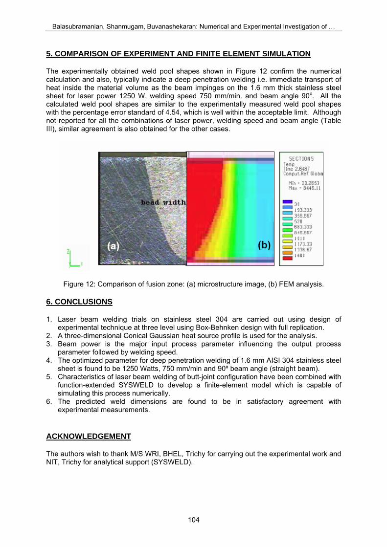
Balasubramanian, Shanmugam, Buvanashekaran: Numerical and Experimental Investigation of … 5. COMPARISON OF EXPERIMENT AND FINITE ELEMENT SIMULATION The experimentally obtained weld pool shapes shown in Figure 12 confirm the numerical calculation and also, typically indicate a deep penetration welding i.e. immediate transport of heat inside the material volume as the beam impinges on the 1.6 mm thick stainless steel sheet for laser power 1250 W, welding speed 750 mm/min. and beam angle 90o. All the calculated weld pool shapes are similar to the experimentally measured weld pool shapes with the percentage error standard of 4.54, which is well within the acceptable limit. Although not reported for all the combinations of laser power, welding speed and beam angle (Table III), similar agreement is also obtained for the other cases.
Figure 12: Comparison of fusion zone: (a) microstructure image, (b) FEM analysis. 6. CONCLUSIONS 1. Laser beam welding trials on stainless steel 304 are carried out using design of
experimental technique at three level using Box-Behnken design with full replication. 2. A three-dimensional Conical Gaussian heat source profile is used for the analysis. 3. Beam power is the major input process parameter influencing the output process
parameter followed by welding speed. 4. The optimized parameter for deep penetration welding of 1.6 mm AISI 304 stainless steel
sheet is found to be 1250 Watts, 750 mm/min and 90º beam angle (straight beam). 5. Characteristics of laser beam welding of butt-joint configuration have been combined with
function-extended SYSWELD to develop a finite-element model which is capable of simulating this process numerically.
6. The predicted weld dimensions are found to be in satisfactory agreement with experimental measurements.
ACKNOWLEDGEMENT The authors wish to thank M/S WRI, BHEL, Trichy for carrying out the experimental work and NIT, Trichy for analytical support (SYSWELD).
104

Balasubramanian, Shanmugam, Buvanashekaran: Numerical and Experimental Investigation of … REFERENCES [1] Mazumder, J.; Steen, W. M. (1980). M.Heat transfer model for cw laser material processing,
Journal of Applied Physics, Vol. 51, Issue 2, 941-947 [2] Goldak, J,; Chakravarti, A.; Bibby, M. (1984). A New finite element model for welding heat
sources, Metallurgical Transactions B, Vol. 15B, 299 305 [3] Frewin, M. R.; Scott, D. A. (1999). Finite Element Model of Pulsed Laser Welding, Welding
Research Supplement, 5s – 22s [4] S.K.Maiti, A. De.; Walsh, C.A.; Bhadeshia, H.K.D.H. (2003). Finite element simulation of laser
spot welding, Science and Technology of Welding and Joining, Vol.8 No.5, 377-383 [5] Tsirkas, S.A.; Papanikos, P.; Kermanidis, Th. (2003). Numerical simulation of the laser welding
process in butt-joint specimens, Journal of Materials Processing Technology, Vol. 134, 59-69 [6] Chang, W.S.; Na, S.J. (2001). Prediction of laser spot weld shape by numerical analysis and
neural network. Metallurgical and Material Transactions B, Vol. 32B, 723-731 [7] Balasubramanian, K.R.; Sankaranarayanasamy, K.; Buvanashekaran, G. (2006). Analysis of
Laser welding parameters using artificial neural network, International Journal for the Joining of Materials, Vol. 18, No. 3/4, 99-104
[8] Balasubramanian, K.R.; Buvanashekaran, G.; Sankaranarayanasamy, K. (2007). Mathematical and ANN modeling of Nd:YAG laser welding of thin SS sheets” Journal Manufacturing Engineering, Vol. 6, Issue 2, 56-60
[9] Meo, M.; Vignjevic, R. Welding Simulation Using FEA, http://www.eng.upm.edu.my/ ~kaa/WEC/WECPapers-FinalVersion/AE 16.doc, accessed on 06.12.2007
[10] ESI-Group. (2007). SYSWELD 2007 Reference Manual [11] Douglas C. Montgomery. (2003). Design and analysis of Experiments, Fifth edition, John Wiley &
Sons [12] Siva Shanmugam, N.; Buvanashekaran, G.; Sankaranarayanasamy, K.; Arunachalam, S. (2007).
Modelling of Temperature Distribution for High Density Heat Source used in Material Joining Process, Proceedings of the 24th International Manufacturing Conference, Waterford Institute of Technology, Waterford, Ireland, August 29-31, 1061-1070
105