Numerical and experimental investigation of bolted joints and experimental investigation of bolted...
12
MultiCraft International Journal of Engineering, Science and Technology Vol. 3, No. 8, 2011, pp. 285-296 INTERNATIONAL JOURNAL OF ENGINEERING, SCIENCE AND TECHNOLOGY www.ijest-ng.com © 2011 MultiCraft Limited. All rights reserved Numerical and experimental investigation of bolted joints J. E. Jam 1 *, N. O. Ghaziani 1 1 Composite Material and Technology Center, Tehran, IRAN * Corresponding Author: e-mail: [email protected] Abstract In this study, the behavior and the damage caused in the bolt joints in sandwich structures with laminates made of glass fiber and foam core is investigated. Many investigators have studied the strength of mechanically bolted joints in composite structures but there is less in sandwich structures. It is performed on a fully composite airplane at the connection area of the wing to the fuselage and the landing gear. The area around the joint is surrounded by the laminates from glass layers (solid laminate) and its thickness is equal to whole thickness of sandwich panel. Different states of connection between the solid laminates, where the bolt connection is imbedded are studied. Also, the foam core around the connection is studied and the dependence of the magnitude of damage on various parameters like the connection angle, size, and the general shape of the solid laminate on buckling is evaluated. For considering the bolted joint performance, a three dimensional finite element model has been developed by ANSYS commercial code. Two proposed circular and squared shape of solid laminate has been considered. The results indicate that the squared shape as compared circular design will decrease the damage significantly. The best solid laminate interface angle ( θ ) which decreases the damage obtains 45 o and solid laminate length is not effective in damage value. Eventually, the effect of these parameters on the local buckling due to the concentrated loading applied to the bolt connection in the sandwich structure is investigated. For confirming the analytical outcomes some experimental models were performed. For testing the analytical results a fixture has been designed. The results of the tests show that the results of the finite element analysis and those of the experimental results are closely related. Keywords: Sandwich Structures, Bolted Joint, Finite Element Method, Solid Laminate DOI: http://dx.doi.org/10.4314/ijest.v3i8.22 1. Introduction Sandwich structures have been widely used in both aerospace and marine applications because of their high stiffness to weight ratio. The first production parts that employed the idea of the modern sandwich structure were produced in the 1940s, but the basic idea was implemented much earlier. Today, the use of sandwich structures in load bearing parts of aircrafts (control surfaces, aerodynamic wing brakes, vertical and horizontal stabilizers) is rapidly increasing. These structures typically employ thin composite laminate face sheets bonded to low density foam cores or honeycombs. One of the main problems of sandwiches because of their low core density is joining the components including sandwich structures by mechanical fasteners. Knowledge of the failure strength would help in selecting the appropriate joint design in a given application. Mechanically fastened joints under tensile loads generally fail in three basic modes, referred to as net tension mode, shear out mode and bearing mode. These modes are shown in (Figure 1). In practice, combinations of these failure modes are possible. Many investigators have studied the strength of mechanically fastened joints in composite structures but there is less investigation in sandwich ones. Chang et al. (1982) have developed a computer code, which can be used to calculate the maximum load and to determine the mode of joints failure in fiber reinforced laminate with different ply orientations, material properties and geometries. They have used Yamada failure criterion. Aktas and Karakuzu (1999) have carried out a failure analysis of mechanically fastened carbon fiber reinforced epoxy composite plate of arbitrary orientation. In that work, failure load and failure mode have been analyzed experimentally and numerically using Tsai-Hill and fiber tensile compressive failure criteria.
Transcript of Numerical and experimental investigation of bolted joints and experimental investigation of bolted...

MultiCraft
International Journal of Engineering, Science and Technology
Vol. 3, No. 8, 2011, pp. 285-296
INTERNATIONAL JOURNAL OF
ENGINEERING, SCIENCE AND TECHNOLOGY
www.ijest-ng.com
© 2011 MultiCraft Limited. All rights reserved
Numerical and experimental investigation of bolted joints
J. E. Jam1*, N. O. Ghaziani1
1 Composite Material and Technology Center, Tehran, IRAN
*Corresponding Author: e-mail: [email protected]
Abstract
In this study, the behavior and the damage caused in the bolt joints in sandwich structures with laminates made of glass fiber and foam core is investigated. Many investigators have studied the strength of mechanically bolted joints in composite structures but there is less in sandwich structures. It is performed on a fully composite airplane at the connection area of the wing to the fuselage and the landing gear. The area around the joint is surrounded by the laminates from glass layers (solid laminate) and its thickness is equal to whole thickness of sandwich panel. Different states of connection between the solid laminates, where the bolt connection is imbedded are studied. Also, the foam core around the connection is studied and the dependence of the magnitude of damage on various parameters like the connection angle, size, and the general shape of the solid laminate on buckling is evaluated. For considering the bolted joint performance, a three dimensional finite element model has been developed by ANSYS commercial code. Two proposed circular and squared shape of solid laminate has been considered. The results indicate that the squared shape as compared circular design will decrease the damage significantly. The best solid laminate interface angle (θ ) which decreases the damage obtains 45o and solid laminate length is not effective in damage value. Eventually, the effect of these parameters on the local buckling due to the concentrated loading applied to the bolt connection in the sandwich structure is investigated. For confirming the analytical outcomes some experimental models were performed. For testing the analytical results a fixture has been designed. The results of the tests show that the results of the finite element analysis and those of the experimental results are closely related. Keywords: Sandwich Structures, Bolted Joint, Finite Element Method, Solid Laminate DOI: http://dx.doi.org/10.4314/ijest.v3i8.22 1. Introduction Sandwich structures have been widely used in both aerospace and marine applications because of their high stiffness to weight ratio. The first production parts that employed the idea of the modern sandwich structure were produced in the 1940s, but the basic idea was implemented much earlier. Today, the use of sandwich structures in load bearing parts of aircrafts (control surfaces, aerodynamic wing brakes, vertical and horizontal stabilizers) is rapidly increasing. These structures typically employ thin composite laminate face sheets bonded to low density foam cores or honeycombs. One of the main problems of sandwiches because of their low core density is joining the components including sandwich structures by mechanical fasteners. Knowledge of the failure strength would help in selecting the appropriate joint design in a given application. Mechanically fastened joints under tensile loads generally fail in three basic modes, referred to as net tension mode, shear out mode and bearing mode. These modes are shown in (Figure 1). In practice, combinations of these failure modes are possible. Many investigators have studied the strength of mechanically fastened joints in composite structures but there is less investigation in sandwich ones. Chang et al. (1982) have developed a computer code, which can be used to calculate the maximum load and to determine the mode of joints failure in fiber reinforced laminate with different ply orientations, material properties and geometries. They have used Yamada failure criterion. Aktas and Karakuzu (1999) have carried out a failure analysis of mechanically fastened carbon fiber reinforced epoxy composite plate of arbitrary orientation. In that work, failure load and failure mode have been analyzed experimentally and numerically using Tsai-Hill and fiber tensile compressive failure criteria.

Jam and Ghaziani / International Journal of Engineering, Science and Technology, Vol. 3, No. 8, 2011, pp. 285-296
286
Figure 1. Three basic failure modes for a bolted joint configuration.
Icten and Sayman (2003) investigated failure load and failure mode in an aluminum/glass epoxy sandwich composite plate,
with a circular hole, which is subjected to a traction force by a pin. To evaluate the effects of joint geometry and fiber orientation on the failure strength and failure mode, parametric studies were performed experimentally. To verify the numerical predictions of mechanical behavior, a series of material configurations ([(0/90)3]s, [(+45)3]s) and twenty different geometries have been investigated. Icten and Karakuzu (2002) concerned with the prediction and examination of the behaviors of the pinned joint carbon/epoxy composite plates. The failure mode and bearing strength are investigated both numerically and experimentally. Two-dimensional finite element method is used to determine the failure load and failure mode using Hoffman and Hashin criteria. Okutan et al. (2001) investigated the failure strength of pin-loaded woven fiberglass reinforced epoxy laminates experimentally and have observed the effects of changing the geometric parameters. Chang (1986) has performed an analysis to evaluate the effect of the assumed pin load distribution. The calculations have utilized a finite element method of stress analysis combined with the Yamada-Sun failure criterion applied along the Chang- Scott Springer characteristic curve. Hung and Chang (1996) performed failure analysis of T800/3900-2 graphite/epoxy materials by using Hashin failure criteria. Pierron and Cerisier (2000) have carried out a numerical and experimental study to determine the stiffness and the bearing strength of bolted woven composite joints. In addition, they have studied for the influence of the clearance. Kretsis and Matthews (1985) showed that as the width of the specimen decreases, there is a point where the mode of failure changes from one of bearing mode to one of tension mode, in using E glass fiber reinforced plastic and carbon fiber reinforced plastic. A similar behavior between the end distance and the shear-out mode of failure was found. They concluded that lay-up had a great effect on both joint strength and failure mechanism. Dano et al. (2007) have developed a finite-element model to predict the response of pin-loaded composite plates. To predict progressive ply failure, four different analyses combining Hashin and the maximum stress failure criteria, and different associated degradation rules were conducted. The influence of the failure criteria and the associated degradation rules on the predictions of the strain around the hole and the bearing stiffness has been determined. Lim et al. (2006) have investigated the fatigue characteristics of the
8 S[ / 0 ]±θ laminate bolted joint. To increase the efficiency of whole structures with the composite bolted joints, the laminate with stacking sequence of 8 S[ / 0 ]±θ has been proposed. It has been determined that the laminates whose major plies were stacked in the axial direction could be used for the bolted joint structures under fatigue load when an appropriate clamping pressure was applied to the bolted joint. Xiao and Ishikawa (2005a,b) have performed an experimental and analytical modeling. The results have indicated that the bearing failure can be outlined as a process of compressive damage accumulation, and can be divided into the following four stages: damage onset, damage growth, local fracture, and structural fracture. The modeling has been performed in the general-purpose finite element code ABAQUS. They have used Hashin and Yamada-Sun’s hybrid failure criteria. In this article a new design for bolted joints in sandwich structures is presented and failure modes and loads of the design are studied. It is performed on a fully composite airplane at the connection area of the wing to the fuselage and the landing gear. The effect of the two variables; solid laminate size and interface angle of foam-solid laminate bonding zone on the performance of the joints are shown numerically. The study is performed based on the three-dimensional finite element method to determine the failure load using Tsai-Wu failure criterion.

Jam and Ghaziani / International Journal of Engineering, Science and Technology, Vol. 3, No. 8, 2011, pp. 285-296
287
2. Problem statement
A bolted joint in a flat sandwich panel in wing to fuselage connection points is investigated. In fact, the solid laminate has the duty of supporting the core against the impacts and other environmental effect (Figure 2). The sandwich panel includes a PVC HT110 foam core with thickness 10mm and shear load P is applied to the bolt head. The panels consist of plain weave glass/epoxy face sheets over a PVC foam core. The face sheets, which consist of two woven glass/epoxy plies, are 0.63mm thick with the material properties listed in Table 1. The PVC foam cores considered were 10mm thick HT110, assumed to be isotropic with the material properties presented in Table 2. All properties were obtained from characterization tests which performed by the authors. The panel size is considered large enough to decrease the effects of boundary condition of the panel. An AN4 bolt and a bush with wall thickness of 2mm was considered the same as ones in real structure.
Figure 2. The bolt connection of a the fuselage of a fully composite airplane (the connection area of the wing to the fuselage)
As was stated earlier, there is no certain pattern for designing and optimizing the bolt design in a sandwich structure. Therefore, by investigating the effective parameters on the operation of the connection, it is tried to introduce a united and optimized pattern. The purpose is finding an optimized design of bolt connection in the sandwich panel with the highest strength and with a safe failure mode. Therefore, knowing the parameters effective in the final answer, they have been investigated, and instead of using the usual approach as in Figure 3, the developed pattern of Figure 4 has been suggested. One of the important parameters in choosing the connection is the shape of the solid laminate, which can be either of circular or square shape.
Figure 3. Ordinary jointed zone design Figure 4. New jointed zone design 3. Numerical study (FEM) A 3D finite element model was created using linear brick elements Solid45 and Solid46 in general commercial FE code ANSYS. To describe the proper loading conditions, the contact surfaces of pin and inserted bush into sandwich panel, was meshed using contact elements Contact173 and Terget170 [14]. Considering geometric and loading symmetry just one half of the model has been meshed and constrained. The panel was clamped at free edges. The size of panel considered large enough to reduce the effect

Jam and Ghaziani / International Journal of Engineering, Science and Technology, Vol. 3, No. 8, 2011, pp. 285-296
288
of boundary conditions at the edges of the panel on the joint. Two models, based on solid laminate shape are investigated. In the first model solid laminate shape is considered to be square, but in second model it has circular shape. Two proposed models are shown in Figure 5 and Figure 6. The imposed force on the head of the bolt is shown in these figures. The mechanical properties of this composite are listed in Table 1 and 2. The properties were obtained from characterization tests, which were performed by the authors. The Young’s modulus, shear modulus, and Poisson’s ratio, tensile strength, compressive strength and shear strength are denoted as E, G, ν, Xt, Xc, S respectively. The material transverse Young’s modulus (E2), transverse tensile (Yt) and compression strength (Yc) are equal to those in the fiber direction because of the woven structure of the lamina. The subscript 1 represents the fiber direction, 2 the direction transverse to the fiber and 3 the normal direction to ply plane. AISI 4130, which widely used in aerospace applications, is considered for the pin and bush.
Table 1. Mechanical properties of glass/epoxy composites Table 2. Mechanical properties of foam HT110 Thickness (mm) 0.315
ν12 0.047
E11 (MPa) 16280
E22 (MPa) 16280
G12 (MPa) 3728
G13 (MPa) 1296
G23 (MPa) 1296
Xt (MPa) 100
Xc (MPa) 100
S (MPa) 47
0.054 ν12
27 E11 (MPa)
13 G12 (MPa)
1.76 Xt (MPa)
1.76 Xc (MPa)
0.86 S (MPa)
Figure 5. Finite element model of square solid laminate Figure 6. Finite element model of circular solid laminate
3.1. Linear static analysis Two squared and circular shape models with foam-solid laminate interface angle 45o and equal volume of solid laminate were chosen to compare the effect of solid laminate shape on damage of the joint. Different criteria are available for the analysis including: Tsai-Hill, Tsai-Wu, Yamada & Sun. But because of the following reasons the Tsai-Wu criterion has been chosen for use:
1- This is a three dimensional criterion. Many of the models used in studies are two dimensional, which cause a bigger inaccuracy and error in comparison with the three dimensional models.
2- The higher accuracies of the studies performed on bolt connections, are possible only by using the three dimensional models for the analysis, and their results are in close connection with the experimental results.

Jam and Ghaziani / International Journal of Engineering, Science and Technology, Vol. 3, No. 8, 2011, pp. 285-296
289
Tsai and Wu (1971) failure criterion is employed to predict the damage in sandwich. Because of linearity of analysis, unit load is applied (1N). Figures 7 and 8 show the Tsai-Wu contour for each model.
Figure 7. Tsai-Wu failure criterion values for square model with interface angle 45o
Figure 8. Tsai-Wu failure criterion values for circular model with interface angle 45o
The contours show that failure occurs in solid laminate to foam bonding zone and the value of failure criterion in circular design is approximately 20% higher than square design. It is also noticeable that failure mode in circular design is net-tension, but in square design it seems like shearing out. Based on these result, parametric study only is performed on the square design. For parametric study, two parameters which define main configurations of a solid laminate are studied. The first parameter is foam-solid laminate interface angle and the second is solid laminate size. To study the effect of foam-solid laminate interface angle on the value of failure criterion in joint zone with a constant size, different foam-solid laminate interface angles 30 45 60 75 90( , , , , )o o o o o are considered. The values of Tsai-Wu failure criterion along two different paths, where maximum damage
has been reported in the structure of airplane, are evaluated. These paths are shown in Figure 9.
Figure 9. Two studied paths The values of Tsai-Wu failure criterion along these paths for different foam-solid laminate interface angles are shown in Figure 10 and 11. As it can be seen in Figure 10, for different foam-solid laminate interface angles the shape of damage diagram along path 1, which is foam to solid laminate interface, is quite different, and for angle in 45o the value of failure criterion (damage) is lowest. It must be noted that for different interface angles, equal distance from the origin of path 1 doesn’t refer to the same position in the laminate. Therefore to attain a graph with comparable normalized position in thickness direction measured from the origin of path 1 is to be defined. Figure 10 represents the thickness position of any selected point along on the horizontal axis as ‘normalized thickness position’. Figure 11 presents an ease of the value of failure criterion at the vicinity of path 2 origin. Meanwhile, interface angle does not have a significant effect on the overall behavior of criterion variations.

Jam and Ghaziani / International Journal of Engineering, Science and Technology, Vol. 3, No. 8, 2011, pp. 285-296
290
Figure 10. The values of Tsai-Wu failure criterion along path 1 for solid laminate with side length 75 mm
Figure 11. The values of Tsai-Wu failure criterion along path 2 for solid laminate with side length 75 mm
To study the effect of solid laminate size five different size of solid laminate with square side length 60, 65, 70, 75 and 80 mm are considered. The foam-solid laminate interface angle in all laminates is 45o . The values of Tsai-Wu failure criterion along these paths for different foam-solid laminate interface angles are shown in Figure 13 and 14. The figures show that the value of failure criterion does not change significantly by changing the size of solid laminate and it will be ultimately damped at a constant distance away from joint zone.
Figure 12. The values of Tsai-Wu failure criterion along path 1 with interface angle 45o
Figure 13. The values of Tsai-Wu failure criterion along path 2 with interface angle 45o
3.2. Buckling analysis Eigenvalue buckling analysis were performed to investigate the effect of bolted joint and its design on the local buckling behavior of sandwich. Different designs of solid laminate were studied. Figure 14 shows the first mode shape of buckling in sandwich with interface angle 45o and solid laminate side length 70mm. As can be seen, local buckling occurs at the end of solid laminate zone due to a tremendous reduction of flexural stiffness at this point.
Jam and Ghaziani / International Journal of Engineering, Science and Technology, Vol. 3, No. 8, 2011, pp. 285-296
291
Figure 14. First buckling mode shape
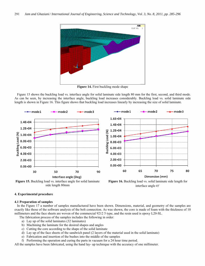
Figure 15 shows the buckling load vs. interface angle for solid laminate side length 80 mm for the first, second, and third mode. As can be seen, by increasing the interface angle, buckling load increases considerably. Buckling load vs. solid laminate side length is shown in Figure 16. This figure shows that buckling load increases linearly by increasing the size of solid laminate.
Figure 15. Buckling load vs. interface angle for solid laminate side length 80mm
Figure 16. Buckling load vs. solid laminate side length for interface angle 45o
4. Experimental procedure
4.1 Preparation of samples In the Figure 17 a number of samples manufactured have been shown. Dimensions, material, and geometry of the samples are exactly like those of the software analysis of the bolt connection. As was shown, the core is made of foam with the thickness of 10 millimeters and the face sheets are woven of the commercial 9212 5 type, and the resin used is epoxy L20-SL.
The fabrication process of the samples includes the following in order: a) Lay up of the solid laminates (32 laminates) b) Machining the laminate for the desired shapes and angles c) Cutting the core according to the shape of the solid laminate d) Lay up of the face sheets of the sandwich panel (2 layers of the material used in the solid laminate) e) Fabrication and insertion of the bushes into the middle of the samples f) Performing the operation and curing the parts in vacuum for a 24 hour time period.
All the samples have been fabricated, using the hand lay- up technique with the accuracy of one millimeter.

Jam and Ghaziani / International Journal of Engineering, Science and Technology, Vol. 3, No. 8, 2011, pp. 285-296
292
Figure 17. Prepared Specimens
The force transfer mechanism and the lamination sequence of the samples in the fixtures have been shown in Figures 18 and 19. Fixture has been designed and manufactured which can meet the requirements of actual boundary condition. Regarding to analytical results, only the squared shape of laminate has been investigated.
Figure 18. The schematic of the designed jigs and fixtures Figure 19. Force transfer mechanism in the designed jigs
and fixtures 4.2 Test Method Due to the complexity of the problems in the region of the tests of the mechanical properties of the composite joints, there is no comprehensive standard in practice for stating the whole test methods in one place. Despite the limitations existing, it was in 2008, when the standards ASTM D7332 were introduced in order to unite the test methods and facilitate the optimization procedures for the composite joints. In this standard, the sub critical criterion of the force- displacement was introduced as the main factor for the behavior of composite joints. From the diagram of failure force diagram, the maximum force and the failure distance can be derived. Also, factors like diameter of the hole, diameter of the connection (bolt or pin), diameter of the connection head, the clearance between connection and the hole, the ratio of diameter to thickness, moment of the connection, the material of the bolt or pin, and also the type of the washer used are effective parameters in the mechanical behavior and shear strength of the composite connections.

Jam and Ghaziani / International Journal of Engineering, Science and Technology, Vol. 3, No. 8, 2011, pp. 285-296
293
Despite the introduction of the current standard, it has no links to the sandwich structures, and due to the lack of a comprehensive standard for this problem, al the standards of ASTM D3039, ASTM D3039, ASTM D3410 had been exactly studied and eventually an standard like ASTM D7332 was chosen. Therefore, the appropriate fixture according to the type and size of the sample was designed and fabricated like the real case, so as to apply the force to a fully shear and one edge state to the sample. The force was uniform and was exerted with a constant speed to the tabs on the two sides of the test device. All the connection up to the observation of the tear in the diagram were under the applied load and according to standard ASTM D7332 the force- displacement diagram indicated the mechanical (statistic) behavior. Also, the failure mode of each sample is one of the behavior characteristics of the composite structures. Twelve composite samples were created, and the properties are described in the table of characteristics. In order to decrease the error in the region of the supposed optimum point (according to the results of the software analysis), two numbers of some samples were created. Other effective parameters on the results and mechanical behavior of the composite joints are: Materials, the fabrication process of the samples, lay-up sequence, hydrothermal conditions, test speed, fiber volume fraction, and the existence of voids in the samples.
Table 3. The number and the properties of the samples produced for the test
solid laminate length angle ( )θ Number of the specimens 1 75mm 30 1 2 75mm 45 2 3 75mm 60 2 4 75mm 75 2 5 75mm 90 1 6 60mm 45 1 7 65mm 45 1 8 70mm 45 1 9 80mm 45 1
Figure 16. Fixture designing Figure 17. Specimen with 75mm of solid laminate length and 45o of θ
4.3 Effect of solid laminate length The size and selected angle 45o are absolutely the same as the analytical method. Load-displacement graphs of all specimens for different length of laminate are shown in Figure 18. According to the results, rupture distance is between 3.7 and 8.3 mm. The average of the failure load is about 8.702 kN with the tolerance of 876 N which is nearly 10% of the average of the failure load value.

Jam and Ghaziani / International Journal of Engineering, Science and Technology, Vol. 3, No. 8, 2011, pp. 285-296
294
Figure 18. Experimental displacement- load behavior of bolted joint for a determined interface angle and difference Solid Laminate size
4.4 Effect of interface angle The load-displacement graph of the specimens with different interface angle and fixed length are shown in Figure 19. According to the results, the specimen with an interface angle 45o has maximum value of the shear resistance, which is similar to that of finite element method. The specimen with an interface angle 90o shows about 20 percent lower strength than the specimen with an interface angle 45o . The results, which are presented in Figure 18, show that the rupture distance is between 3.7 and 8.5 mm. The average of the failure load is determined about 8.149 kN with the tolerance of 1916N from experimental result.
Figure 19. Displacement-Force behavior for a certain solid laminate length and different interface angle
4.5 Investigation of the dissipation factors and error in the experiments According to the standard ASTM D7332, different factors are effective in the final results of the composite joints, including diameter of the hole, diameter of the connection, the clearance between connection and the hole, the material of the bolt or pin, and the other stated factors. But, regarding the differences of the discussed problem and the special design of the jigs and fixtures, some other various factors other than those stated above must also be considered. The first and most important factors effective in the results of the tests is the kinking of the edges of the sample while applying the shear loadings. This kinking is caused at the interfaces in the plates of the fixture.

Jam and Ghaziani / International Journal of Engineering, Science and Technology, Vol. 3, No. 8, 2011, pp. 285-296
295
Slippage of the bush, though small, while applying the load is one of the other important factors in the error of the practical results. Because of the predictability of this phenomenon, maximum attention is paid to accuracy while fabricating the final parts. One of the measures done in order to prevent this shortcoming is creating grooves along the external wall of the bushes, whilst separating the bush in the solid laminate.
Figure 20. Separation of the bush whilst applying the force One of the other factors effective in the results is the weight of the parts of the fixtures, because of its special design can have slight impact on the results. It is necessary to point out that the achieved displacement is the sum of the displacement of the jig and fixture and that of the bolt jointed sample. Although the metallic chosen type (MO40) has a much less strain against the applied load, but has its own impact on the final result. Damage caused to the bolt and washers are the other effective factors in the results. As can be seen in Figure 21, failure mode in all specimens, is near to shearing-out shape. It is noticeable that this mode is safer than the other modes. In some specimens some unpredicted fracture has been observed which has been shown in Figure 22. This phenomenon could be the result of some high stress concentration at the boundary of fixture.
Figure 21. Shearing-out shape of fracture (L=75mm, θ= 45o ) Figure 22. Unpredicted fracture at the edge of sample 5. Conclusion A new design was developed for bolted joints in foam-core sandwich panels with composite face sheet. The effect of different parameters of new design on the damage of joined zones was investigated numerically. Two designs based on the shape of solid laminate, a circular and rectangular design, were considered for the study. Results indicate that by using the rectangular design, the Tsai-wu failure criterion value will decrease considerably in comparison with design. It is also observed that in the circular design the specimens tear and the failure mode is net-tension but in the rectangular design the failure mode is shearing-out. The study also shows that the solid laminate to foam interface angle plays an important role on the failure criterion value. The results of static analysis on specimens with an interface angle 45o show higher strength than specimens with other angles, while specimens with 90o interface angle have the lowest strength. Also for a specified angle, (45 )o the failure criterion values decrease both long path 1 and path 2 as the solid laminate size increases. It must be noted that the points with larger distance with respect to the origin along

Jam and Ghaziani / International Journal of Engineering, Science and Technology, Vol. 3, No. 8, 2011, pp. 285-296
296
paths 1 and 2 encounter smaller values of failure criterion values except in the vicinity of the origin of path 2. Therefore, this could ensure the designer about other points of the laminate if the design could satisfy the safety of this area as critical points. On the other hand, the solid laminate size does not have considerable effect on Tsai-Wu vs. distance both along path 1 and path 2 and similar behavior could be observed. Eigenvalue buckling analyses were performed on the finite element models to predict the buckling load. It is shown that by increasing the interface angle or solid laminate size, buckling load increases significantly. So, in a buckling case, the specimens with 90o interface angle show higher buckling strength. The verification of the results from finite element analysis for the square shape is carried out. The results of the finite element analysis are close to the experimental results. The discrepancy of the two methods are due to: error in the fabrication of samples, voids caused in the fabrication process, inappropriate geometry of the fixture to reality, strains caused in the fixtures and other numerous factors. References Aktas A. and Karakuzu R., 1999. Failure analysis of two-dimensional carbon–epoxy composite plate pinned joint. Mechanics of
Composite Materials, Vol. 6, pp. 347–361. ANSYS 9 Users Manual, 2002, Swanson Analysis Systems, Houston, PA. Chang F.K., Scott R.A. and Springer G.S., 1982. Strength of mechanically fastened composite joints. Journal of Composite
Materials, Vol. 16, pp. 470–494. Chang F.K., 1986. The effect of pin load distribution on the strength of pin loaded holes in laminated composites. Journal of
Composite Materials, Vol. 20, pp. 401–408. Dano, M., Kamal, E. and Gendrom, G., 2007. Analysis of bolted joints in composite laminates: Strains and bearing stiffness
predictions. Composite Structures, Vol. 79: pp. 562-570. Hung C.L. and Chang F.K., 1996. Bearing failure of bolted composite joints. Part II: Model and verification. Journal of Composite
Materials, Vol. 30, pp. 1359–1400. Icten B.M. and Sayman O., 2003. Failure analysis of pin-loaded aluminum–glass–epoxy sandwich composite plates. Composites
Science and Technology, Vol. 63, pp. 727–737. Icten B.M. and Karakuzu R., 2002. Progressive failure analysis of pin loaded carbon epoxy woven composite plates. Composites
Science and Technology, Vol. 62, pp. 1259–1271. Kretsis G. and Matthews F.L., 1985. The strength of bolted joints in glass fiber/epoxy laminates. Journal of Composite Materials,
Vol. 16, pp. 92–102. Lim T.S., Kim B.C., and Lee D.G., 2006. Fatigue characteristics of the bolted joints for unidirectional composite laminates,
Composite Structures, Vol. 72: pp. 58-68. Okutan B., Aslan Z., and Karakuzu R., 2001. A study of the effects of various geometric parameters on the failure strength of pin-
loaded woven–glass–fiber reinforced epoxy laminate. Composites Science and Technology, Vol. 61, pp. 1491–1497. Pierron F. and Cerisier F., 2000. A numerical and experimental study of woven composite pin-joints. Journal of Composite
Materials, Vol. 34, pp. 1028–1054. Tsai S.W. and Wu E. M., 1971. A general failure criterion for anisotropic materials. Journal of Composite Materials, Vol. 6, pp.
58–80. Xiao Y. and Ishikawa T., 2005a. Bearing strength and failure behavior of bolted composite joints. Part I: Experimental
investigation. Composites Science and Technology, Vol. 65: pp. 1022-1031. Xiao Y. and Ishikawa T., 2005b. Bearing strength and failure behavior of bolted composite joints. Part II: Modeling and
simulation. Composites Science and Technology, Vol. 65: pp. 1032-1043. Biographical notes N. O. Ghaziani received his M. Sc. degree in 2011 from Bu-Ali Sina University, Iran. Presently His current area of research includes Fatigue and Fracture Mechanics, Buckling, composite. J. E. Jam works with Composite Material and Technology Center, Tehran, Iran. Received November 2011 Accepted June 2012 Final acceptance in revised form June 2012