NUMERICAL AND EXPERIMENTAL ANALYSES OF VANE AND … Frosina.pdfNumerical and experimental analyses...
22
NUMERICAL AND EXPERIMENTAL ANALYSES OF VANE AND PISTON PUMPS University of Naples “Federico II” Department of Industrial Engineering Fluid Power Research Group West Lafayette June 4 th , 2019 FPRG – FLUID POWER RESEARCH GROUP
Transcript of NUMERICAL AND EXPERIMENTAL ANALYSES OF VANE AND … Frosina.pdfNumerical and experimental analyses...
NUMERICAL AND EXPERIMENTAL ANALYSES OF VANE AND PISTON
PUMPS
University of Naples “Federico II”
Department of Industrial Engineering
Fluid Power Research Group
West Lafayette June 4th, 2019
FPRG – FLUID POWER RESEARCH GROUP

Index
June 4th, 2019Fluid Power Research Group
Numerical and experimental analyses of vane and piston pumps
– FPRG – University of Naples “Federico II”
– Vane pumps:
Vane Dynamic
Chamber filling
– Piston pumps
Valve plate design model
Lumped parameter CV approach
–2

June 4th, 2019Fluid Power Research Group
Numerical and experimental analyses of vane and piston pumps
Fluid Power Research Group
3
Vane
Pump
Piston Pump
Spool Valve
Gerotor
Pump
Numerical modeling simulations: 1D and 3D CFD approaches

June 4th, 2019Fluid Power Research Group
Numerical and experimental analyses of vane and piston pumps
Pumps: experimental setup
Lubrication
Pumps
Pressure ripple
Flow-rate
Torque
Cavitation phenomenon 0 60 120 180 240 300 360Angle [Deg]
0.76
0.8
0.84
0.88
0.92
0.96
1
No
rma
lize
d p
ressu
re
2000rpm-3bar
Fluid Power Research Group
4

June 4th, 2019Fluid Power Research Group
Numerical and experimental analyses of vane and piston pumps
Valves: experimental setup
Hydraulic
valves
Pressure
Flow-rate
Cavitation phenomenon
Fluid Power Research Group
5
June 4th, 2019Fluid Power Research Group
Numerical and experimental analyses of vane and piston pumps
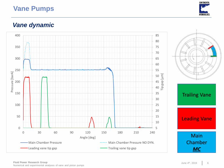
Vane Pumps
Vane dynamic
Main Chamber
MC
Leading Vane
Trailing Vane
6
5
10
15
20
25
30
35
40
45
50
55
60
65
70
75
80
85
0
50
100
150
200
250
300
350
400
0 30 60 90 120 150 180 210 240
Tip
gap
[μm
]
Pre
ssu
re [b
arA
]
Angle [deg]
Main Chamber Pressure Main Chamber Pressure NO DYN.
Leading vane tip gap Trailing vane tip gap

June 4th, 2019Fluid Power Research Group
Numerical and experimental analyses of vane and piston pumps
Vane Pumps
Vane dynamic
𝐹𝑡 = 𝐹𝑝 + 𝐹𝑐 + 𝐹𝑓
The contact force for each vane can be evaluated using the following equation:
Where:
• 𝐹𝑝 = 𝑝𝑟,𝑢𝑣 ∙ 𝐴𝑢𝑣 − 𝑝𝑟,𝑡𝑣 ∙ 𝐴𝑡𝑣
• 𝐹𝑐 = 𝑚𝑣 ∙ 𝜔2 𝜌 −𝑙𝑣
2The vector ray 𝜌 is: 𝜌 = 𝑒2 + 𝑅𝑆
2 + 𝑒𝑅𝑠 cos 𝜑 + 𝛿
-200
0
200
400
600
800
1000
1200
1400
1600
1800
2000
2200
2400
0 30 60 90 120 150 180 210 240 270 300 330 360
Forc
e [N
]
Angle [deg]
Bottom Force Tip Force Contact Force
7
June 4th, 2019Fluid Power Research Group
Numerical and experimental analyses of vane and piston pumps
-1200
-700
-200
300
800
1300
1800
2300
0 60 120 180 240 300 360
Forc
e [N
]
Angle [deg]
Contact force Vane tip - Stator ring
v0.00 v1.00 v1.01 v1.02
v1.00 v1.01 v1.02
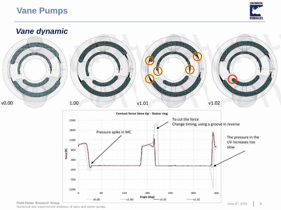
Vane Pumps
Vane dynamic
To cut the forceChange timing, using a groove in reverse
The pressure in the UV increases too slow
Pressure spike in MC
v0.00
8

June 4th, 2019Fluid Power Research Group
Numerical and experimental analyses of vane and piston pumps
Vane Pumps
Vane dynamic
70
75
80
85
90
95
45 60 75 90 105 120 135 150 165 180
Inst
anta
ne
ou
s fl
ow
[L/m
in]
Angle [deg]v0.00 v1.00 v1.01 v1.02
9
June 4th, 2019Fluid Power Research Group
Numerical and experimental analyses of vane and piston pumps
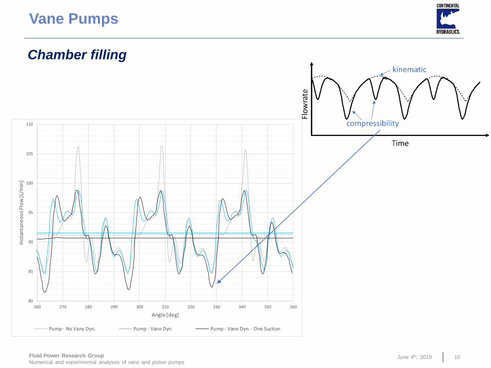
Vane Pumps
Chamber filling
80
85
90
95
100
105
110
260 270 280 290 300 310 320 330 340 350 360
Inst
anta
ne
ou
s Fl
ow
[L/m
in]
Angle [deg]
Pump - No Vane Dyn. Pump - Vane Dyn. Pump - Vane Dyn. - One Suction
10
June 4th, 2019Fluid Power Research Group
Numerical and experimental analyses of vane and piston pumps
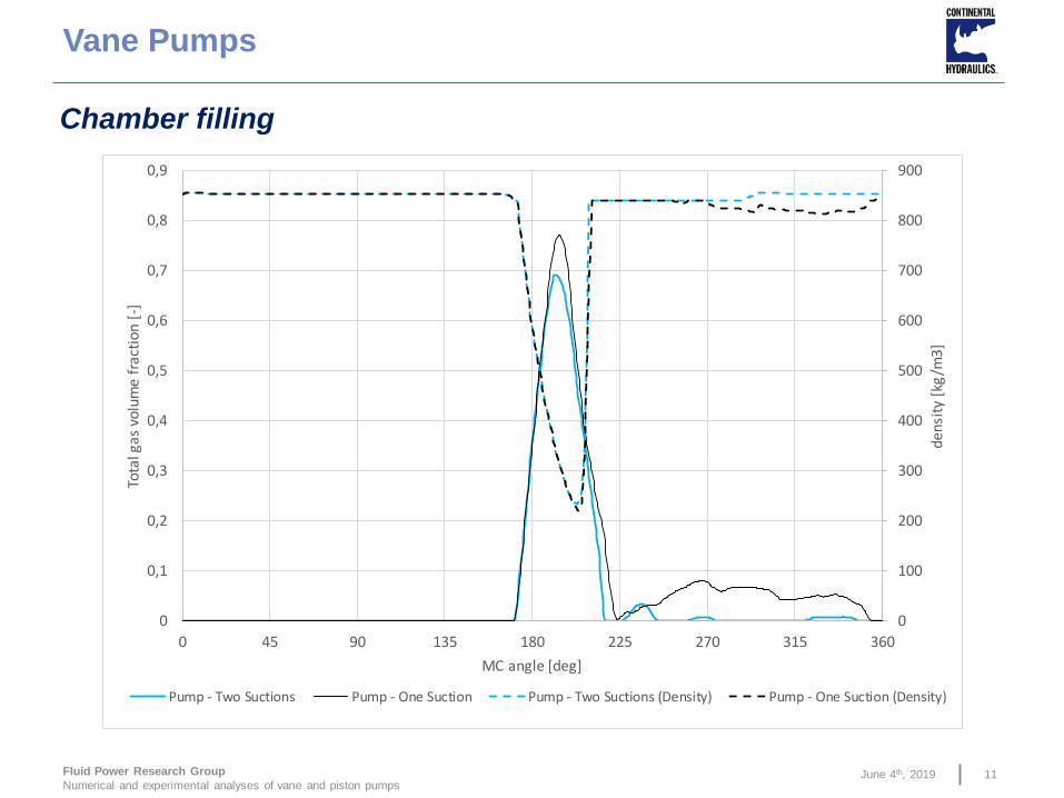
Vane Pumps
Chamber filling
0
100
200
300
400
500
600
700
800
900
0
0,1
0,2
0,3
0,4
0,5
0,6
0,7
0,8
0,9
0 45 90 135 180 225 270 315 360
den
sity
[kg
/m3
]
Tota
l gas
vol
ume
frac
tion
[-]
MC angle [deg]
Pump - Two Suctions Pump - One Suction Pump - Two Suctions (Density) Pump - One Suction (Density)
11

June 4th, 2019Fluid Power Research Group
Numerical and experimental analyses of vane and piston pumps
Different vane types:
Hydrodynamic Load Capacity
Vane Pumps: Future Works
Vane tip profile
12
June 4th, 2019Fluid Power Research Group
Numerical and experimental analyses of vane and piston pumps
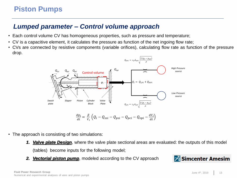
• Each control volume CV has homogeneous properties, such as pressure and temperature;
• CV is a capacitive element, it calculates the pressure as function of the net ingoing flow rate;
• CVs are connected by resistive components (variable orifices), calculating flow rate as function of the pressure
drop.
𝑑𝑝𝑖𝑑𝑡
=𝛽
𝑉𝑖𝑄𝑖 − 𝑄𝑠𝑠𝑖 − 𝑄𝑝𝑠𝑖 − 𝑄𝑝𝑐𝑖 − 𝑄𝑣𝑝𝑖 −
𝑑𝑉𝑖𝑑𝑡
Control volumeQpciQpsiQssi
Qvpi
pi
Swashplate
Slipper Piston CylinderBlock
Valve Plate
) () (
Low Pressure source
High Pressure source
𝑄𝐻𝑃𝑖 = 𝑐𝑑𝐴𝐻𝑃𝑖2 𝑝𝑖 − 𝑝𝐻𝑃
𝜌
𝑄𝐿𝑃𝑖 = 𝑐𝑑𝐴𝐿𝑃𝑖2 𝑝𝑖 − 𝑝𝐿𝑃
𝜌
𝑄𝑖 = 𝑄𝐿𝑃𝑖 + 𝑄𝐻𝑃𝑖
Lumped parameter – Control volume approach
• The approach is consisting of two simulations:
1. Valve plate Design, where the valve plate sectional areas are evaluated: the outputs of this model
(tables) become inputs for the following model;
2. Vectorial piston pump, modeled according to the CV approach
Piston Pumps
13

June 4th, 2019Fluid Power Research Group
Numerical and experimental analyses of vane and piston pumps
Kidney
Supercomponent
Groove
Supercomponent
The model has two main supercomponents:
• Groove SC, to evaluate the slots;
• Kidney SC, to evaluate the kidneys opening areas.
1 – Valve plate design model
Angular position
of cylinder
Hydraulic diameter
of turbulent orifice
Area
of turbulent orifice
Angular position
of cylinder
Hydraulic diameter
of turbulent orifice
Area
of turbulent orifice
Piston Pumps
14
June 4th, 2019Fluid Power Research Group
Numerical and experimental analyses of vane and piston pumps
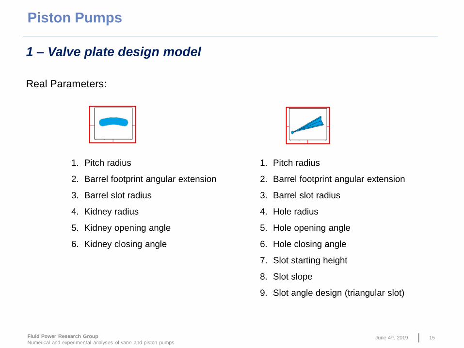
Real Parameters:
1. Pitch radius
2. Barrel footprint angular extension
3. Barrel slot radius
4. Kidney radius
5. Kidney opening angle
6. Kidney closing angle
1. Pitch radius
2. Barrel footprint angular extension
3. Barrel slot radius
4. Hole radius
5. Hole opening angle
6. Hole closing angle
7. Slot starting height
8. Slot slope
9. Slot angle design (triangular slot)
1 – Valve plate design model
Piston Pumps
15

June 4th, 2019Fluid Power Research Group
Numerical and experimental analyses of vane and piston pumps
Barrel
footprint
1 – Valve plate design model
Hole area:
In red the
area
evaluated
by the
Groove SC
Limited by:
Piston Pumps
16

June 4th, 2019Fluid Power Research Group
Numerical and experimental analyses of vane and piston pumps
Slot area: the slope angle is considered
1 – Valve plate design model
Kidney area and its limit (barrel footprint area):
Piston Pumps
17

June 4th, 2019Fluid Power Research Group
Numerical and experimental analyses of vane and piston pumps
High pressure side
Low pressure side
Portplate model overview
Po
rtp
late
to m
od
el
Example of modeling:
1 – Valve plate design model
Piston Pumps
18

June 4th, 2019Fluid Power Research Group
Numerical and experimental analyses of vane and piston pumps
1 – Valve plate design model
Example of modeling:
Piston Pumps
19
June 4th, 2019Fluid Power Research Group
Numerical and experimental analyses of vane and piston pumps
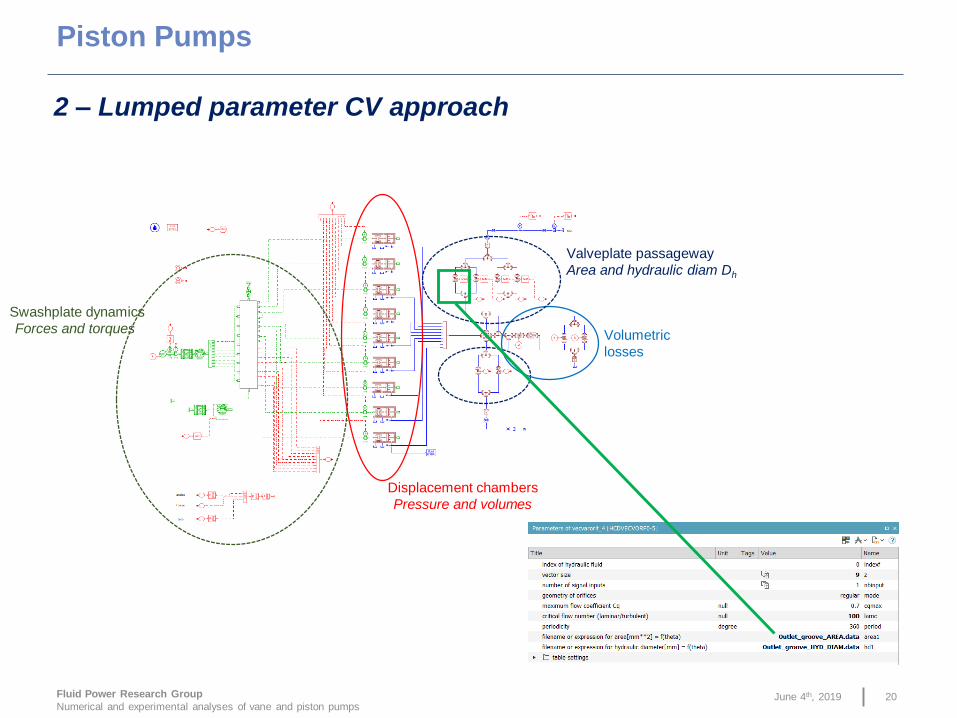
Displacement chambers
Pressure and volumes
Swashplate dynamics
Forces and torques
Valveplate passageway
Area and hydraulic diam Dh
Volumetric
losses
2 – Lumped parameter CV approach
Piston Pumps
20

June 4th, 2019Fluid Power Research Group
Numerical and experimental analyses of vane and piston pumps
The approach is validated comparing the
results with a CFD simulation:
Here is showed a comparison on a pressure
ripple:
Pressure monitoring point (CFD3D)
Approach validation
Piston Pumps
21

West Lafayette June 4th, 2019
FPRG – FLUID POWER RESEARCH GROUP
22
Emma FrosinaAssistant Professor
Department of Industrial Engineering
University of Naples, Italy