
Numerical Analysis of the Structural Stability of Heat ...
24
7 Numerical Analysis of the Structural Stability of Heat Exchangers – The FEM Approach Agnieszka A. Chudzik Technical University of Lodz/Department of Machine Dynamics Poland 1. Introduction A demand for improved computational methods of complex systems used in modern structures has been followed by development of theory and analysis in the field of stability of shell structures. Nonlinear problems, in which, for instance, shape imperfections, complex loads, nonelastic properties of the material used in the structure are accounted for, are of deep interest. Thanks to an advance in computer technology and numerical methods, a possibility to conduct more precise analysis which corresponds better to actual structures of mathematical models arises. In the linear and nonlinear analysis of structures, stability occupies a special place. To test the load carrying capacity of the structure, the phenomena that occur during a stability loss and after it should be recognized. An application of thin- wall elements results in advantages such as light weight, a possibility to carry high loads, thermo-insulating properties, etc. Here, analysis and recognition of transfer phases since an appearance of plastic strains up to a complete reduction of the load carrying capacity is essential. A demand for such complex analysis that includes stability and leads to more actual evaluation of the structure safety has been observed in many disciplines of technology, e.g., in designing of ships, airplanes, pressure chemical apparatus, in modern construction industry and in power and heat generation. Heat exchangers that are widely applied in, e.g., power and heat generation, operate under very high temperatures. The principal elements of these devices are perforated walls – perforated plates in which heating cartridge pipes are fixed. The number of pipes, i.e., of holes in the plate, is very high and these holes are separated from one another by a thin bridge. The issue of differences in temperatures in individual parts of the heat exchanger and in various media that flow in the device is a source of considerable design difficulties. Heat exchangers usually operate under pressure or in vacuum. Independently of the fact that not only the knowledge of material strength properties is needed for computations of heat exchangers, there are legal regulations that standardize the calculations of the devices operating under pressure. They define the way the basic parts are calculated, providing thus hints concerning the structure of the devices under control. A decrease in the safety factor due to stability, i.e., a rapprochement to the real state of stress up to the critical one, is the way the modern engineering structures can be characterized by. Therefore, the calculations of stability, stiffness of thin-walled structural elements are becoming more and more important nowadays in designing and performance of many devices. A heat exchange is a common phenomenon in technology and nature – it occurs when there are differences in www.intechopen.com
Transcript of Numerical Analysis of the Structural Stability of Heat ...

7
Numerical Analysis of the Structural Stability of Heat Exchangers – The FEM Approach
Agnieszka A. Chudzik Technical University of Lodz/Department of Machine Dynamics
Poland
1. Introduction
A demand for improved computational methods of complex systems used in modern structures has been followed by development of theory and analysis in the field of stability of shell structures. Nonlinear problems, in which, for instance, shape imperfections, complex loads, nonelastic properties of the material used in the structure are accounted for, are of deep interest. Thanks to an advance in computer technology and numerical methods, a possibility to conduct more precise analysis which corresponds better to actual structures of mathematical models arises. In the linear and nonlinear analysis of structures, stability occupies a special place. To test the load carrying capacity of the structure, the phenomena that occur during a stability loss and after it should be recognized. An application of thin-wall elements results in advantages such as light weight, a possibility to carry high loads, thermo-insulating properties, etc. Here, analysis and recognition of transfer phases since an appearance of plastic strains up to a complete reduction of the load carrying capacity is essential. A demand for such complex analysis that includes stability and leads to more actual evaluation of the structure safety has been observed in many disciplines of technology, e.g., in designing of ships, airplanes, pressure chemical apparatus, in modern construction industry and in power and heat generation. Heat exchangers that are widely applied in, e.g., power and heat generation, operate under very high temperatures. The principal elements of these devices are perforated walls – perforated plates in which heating cartridge pipes are fixed. The number of pipes, i.e., of holes in the plate, is very high and these holes are separated from one another by a thin bridge. The issue of differences in temperatures in individual parts of the heat exchanger and in various media that flow in the device is a source of considerable design difficulties. Heat exchangers usually operate under pressure or in vacuum. Independently of the fact that not only the knowledge of material strength properties is needed for computations of heat exchangers, there are legal regulations that standardize the calculations of the devices operating under pressure. They define the way the basic parts are calculated, providing thus hints concerning the structure of the devices under control. A decrease in the safety factor due to stability, i.e., a rapprochement to the real state of stress up to the critical one, is the way the modern engineering structures can be characterized by. Therefore, the calculations of stability, stiffness of thin-walled structural elements are becoming more and more important nowadays in designing and performance of many devices. A heat exchange is a common phenomenon in technology and nature – it occurs when there are differences in
www.intechopen.com

Heat Exchangers – Basics Design Applications
166
temperatures. A trial to determine the conditions under which a stability loss will occur in the elements of the heat exchanger that are most exposed to this threat is presented in this paper.
2. Formulation of the problem
Heat exchangers have versatile industrial applications. They are widely used in the food and chemical industry and in energy and power generation, etc. The heat exchanger very often stops to be used as a separate device, designed solely for the heat exchange and its role is connected with other tasks as well. In such a case, the heat exchanger is a part of a facility used for some technological processes. A versatility of applications of heat exchangers is followed by a high diversity in their designs. Various conditions of the process and properties of the substances heated up or cooled, condensed or evaporated result in a necessity to select the material strength properties and the design itself in a proper way. The analysis of an effect of the perforated plate on structural elements of the heat exchanger is an important issue in designing and operation of these devices Hobler (1986), Horak (2005). Working temperatures of the media flowing in the heat exchanger have a decisive impact on the design. In the initial phase of designing, the designer is interested in values of applied temperatures and differences in temperatures between individual elements of the device. The magnitude of the applied temperatures decides about the selection of materials used in the designed structure (due to their strength properties). With an increase in the temperature, ”volume” of the materials applied for elements of the heat exchanger increases. The dimensions of a jacket, perforated plates, heating cartridge pipes, bottoms, as well as any other part of the heat exchanger are subject to alternations. This phenomenon is referred to as heat dilatation. Differences in temperatures of the media working in the heat exchanger cause various heat dilatations, for instance, pipes elongate in a different way than the jacket does, a diameter of the perforated bottom changes differently than the outer wall, etc. Heat dilatations are the most cumbersome problem for the designer of heat exchangers as they can cause considerable stresses in the material that can lead to plastic strains or even a failure of the device. The jacket attains the temperature close to the temperature of the flowing medium with which it comes into contact, pipes have a different temperature outside and inside. A difference in these temperatures, as well as in pressure of the flowing media that results from the task the heat exchager is to fulfill can be considerable. In strength calculations, the designer considers the creep strength limit or the creep limit. They both are time functions. Design difficulties very often arise when a difference in working temperatures in various parts of the heat exchanger is accounted for. Significant changes in strength characteristics of the material occur along with alternations in its temperature, namely: an increase in temperature makes the material more plastic, the tensile strength Rm and the immediate yield point Re become lower. Strength tests have shown that at higher temperatures, the duration of stress affects strongly the strength and the yield point. Then, the plastic strain of the element depends on: stress, time and temperature. The designer decides thus what material to choose for the elements of the structure to postpone possible plastic strains or a structural failure beyond the predicted operating life. The issues related to computations of circular-symmetrical disks are very important problems in the theory of elasticity and plasticity. Many researchers have investigated also the problem of assembly of pipes in holes of the perforated bottom Ryś (2003). The problem of strength and tightness of such a connection gives rise to serious difficulties to heat exchanger manufacturers.
www.intechopen.com

Numerical Analysis of the Structural Stability of Heat Exchangers – The FEM Approach
167
Numerous studies quote results of the analysis of mathematical models. These studies include, however, significant simplifications as regards actual operating conditions, shapes of the calculated elements, the manufacturing technology of connections, and the behavior of materials under operating conditions. Analytical methods consist in a separation of the fragment from the perforated plate among the surrounding heating pipes, assuming the boundary conditions for the operation of the cut circular plate and applying the pressure. The elastic behavior of the background (pipes) is usually not accounted for, the plate edge is treated as fixed (or other boundary conditions), which is very far from the reality. These engineering simplifications of assumptions result in considerable differences between values of actual stresses and those obtained experimentally. Calculations made with the FEM can be the way the majority of the above-mentioned factors are accounted for Chudzik (2002,2008).
2.1 Aim of the investigations
Differences in the temperatures heat exchangers operate in can result in a remarkable difference in heat displacements. These displacements can give rise to high stresses and strains in parts of heat exchanger such as pipes, jackets and bottoms. An increase in stresses and strains is especially dangerous in case of a failure. It can lead to loads that can result in a stability loss of the perforated bottom together with heating cartridge pipes. A stability loss of the pipe does not have to be followed by damage, but the effects it will cause in the structure depend on the kind and the nature of buckling. A deflection or a shortening of the pipe axis (global stability) that can result in exceeding inconsiderably the critical force may lead to a rapid increase in stresses. When the pipe in the complex structure is buckled, it looses its stability, which can lead to a stability loss of the whole structure. In thin-walled pipes, a new phenomenon has occurred, i.e., local stability. As opposed to global stability, it consists in the fact that the cross-section of the pipe deforms and the rod axis remains straight. Critical stresses under the local stability loss are calculated on the basis of the theory of plates and shells. Analytical calculations of the above-mentioned phenomena give rise to some difficulties. The FEM enables an accurate reproduction of the structure, as well as of the manufacturing technology and the assembly of the heat exchanger. Thus, the calculations of the heat exchanger as regards its stability loss can be carried out. A one-cycle heat exchanger working as a water heater is chosen for our analysis. The perforated bottom of these heat exchangers is an expensive and difficult to manufacture element and, therefore, it is economically justified to decrease its mass. That is why the FEM calculations aimed at a more accurate analysis whose results could affect possible alternations in the heat exchanger design, e.g., through a decrease in the perforated bottom thickness, have been conducted. The calculations are a continuation of the investigations carried out formerly (Chudzik, 2002; 2008).
3. Stability – a literature survey
First studies devoted to stability loss issues were already published more than seven decades ago Zielnica (2001) and they dealt with elastic-plastic shells. An intensive development has been observed since 1955, when Gerard (1956), Lee (1961,1962), Grigoluk (1957) and other researchers published their works. For instance, Sewell (1972), Hutchinson (1972,1973) proposed the methods and the results of solutions to problems of elastic-plastic
www.intechopen.com

Heat Exchangers – Basics Design Applications
168
stability of structures made of pipes, plates and shells, Nowak and hyczkowski (1963) are responsible for a survey of shell structures. Iiiuszyn (1944) developed the fundamentals of the stability theory of thin-walled shells made of an incompressible material with arbitrary characteristics of reinforcement beyond the elastic limit. Zielnica (1969), Bijlaard (1950), Murphy and Lee (1971), Gellin (1979), Hardig (1978), Sobel and Newmann (1982) – these are the researchers who blazed a trail in the analysis of shell stability to follow as they dealt with:
determination of bifurcation loads (eigenvalues) in the linear range under the membrane precritical state of stresses,
determination of bifurcation points on nonlinear paths or critical loads under geometrical nonlinearities in the precritical state, accounting for bending effects before the stability loss and determination of nonlinear equilibrium paths including imperfections (shape imperfections),
application of the FEM method to determine nonlinear paths of the subcritical equilibrium.
In 1947 Shanley presented a new concept of the stability loss in rods, referred to as buckling under increasing load. The stability investigations of the jointly supported rod under compression showed that the rod was subject to buckling and the axial force compressing the rod grew simultaneously after it reached the critical load. Shanley’s concept of buckling under critical load enabled to simplify the stability equations as in that case the limit that separates the active process zone from the deloading zone does not have to be established.
In the uniaxial state of stresses (rod systems), the stability analysis can be based on the actual material characteristics obtained from, e.g., the uniaxial elongation test.
In the biaxial state of stresses (shells, plates), the knowledge of material characteristics is not enough as in the case discussed above. To determine the dependence between components of the tensor of the stress and strain state beyond the elastic limit, one should go into detail in the theory of plasticity. Nowadays there are numerous publications devoted to this issue. The majority of them include solutions to comparatively simple models exposed to a stability loss. If the literature survey were to be further discussed here, it could take a form a separate book. The author’s task was, however, to conduct a numerical analysis of the more complex device such as the heat exchanger is. A demand for such calculations result from a lack of studies presenting the calculation methods, numerical computations, results of the calculations of, e.g., more complex experimental structures as regards their stability loss. Experimental investigations to compare the results would be very expensive. The results of the experiment will be followed by the need to lead the device to a failure. A mathematical analysis of such a device also gives rise to many difficulties to researchers due to complexity of the problem and the device.
3.1 Stability of load carrying elements of the structure
The behavior of load carrying elements of the structure under increasing loads can be divided into a few phases of their operation, namely: linear in the precritical state, postbuckling elastic under considerable deflections, postcritical elastic-plastic and a failure.
www.intechopen.com

Numerical Analysis of the Structural Stability of Heat Exchangers – The FEM Approach
169
The first three phases are of fundamental importance to designers. In order to determine
boundaries between these phases, the following should be known: the critical load, the load
at which first plastic deformations occur and the limit load understood as the maximum
load after which the damage of the structure will start.
Phase I, the prebuckling phase, occurs when the behavior of the element is described with
the classical linear theory. A solution (analytical or numerical) to this problem does not give
rise to serious difficulties. Phase II is characterized by high deflections. Due to this fact, the
problem becomes geometrically nonlinear whereas physically it is still linear, and its
solution allows one to analyze the behavior of the structure until the limit of proportionality
is attained. Different modes of buckling can occur in this phase: local and global. An
appearance and development of plasticized regions are characteristic of phase III. An
analysis and knowledge of the structure in this phase is very useful and needed in the
designing process as the load of the structure attains the maximal value in this phase. The
determination of the value of this load, referred to as the limit load carrying capacity,
requires a physical and geometrical solution to the nonlinear problem of stability. A full
analysis in the elastic-plastic range consists in taking into account numerous phenomena
that occur in real structures (initial imperfections, interactions of different modes of
buckling, the “shear lag” phenomenon, etc.). Despite such a complex issue, many problems
related to, e.g., plates subject to simple loads, rectangular plates under uniform
compression, have already been solved and the results are supported by the corresponding
experimental investigations. However, there is a large group of structures subject to
complex loads, whose structure is more sophisticated and for which the determination of
the limit load carrying capacity via solution to the stability problem under high deflections
in the elastic-plastic range is very complicated even if up-to-date computational numerical
methods are employed. Therefore, modern engineering structures during the designing
process are based on theories of elasticity on the assumption of high deflections which allow
for determination of the load at which plasticization of the structure begins. This state is
referred to as the limit state and it is treated as a sort of failure criterion that allows one to
design a safe structure although sometimes not an economically favorable one Królak at al
(1990).
4. The model under investigation
The calculations were made for a one-cycle heat exchanger, Fig. 1, whose model has been
developed on the basis of the technical documentation of the Py-100-020 decarbonized water
heater.
The elements that were taken into account in the 3D model of the heat exchanger are as
follows: perforated plates (1), bottoms (2), a jacket (3), heating cartridge pipes (8), heating
cartridge gaskets (10) shown in Fig.1. Perforated plates are fixed to bottoms with screw
fasteners (9). Connector pipes (6) and (7) supply and take off the steam. Detail B shows
dimensions of the hole in the perforated bottom before rolling out and a view of the pipe-
perforated bottom connection after rolling out. The perforated plates have a hexagonal
system of holes that make perforations. The materials used in the structure are listed in
Table 1.
www.intechopen.com

Heat Exchangers – Basics Design Applications
170
Fig. 1. Schematic view of the heat exchanger.
I - K10
PN-74/H-74252 boiler pipe
St41K PN-75/H-92123
boiler sheet
St 36K PN-75/H-92123
boiler sheet
yield point Re =235 MPa Re =255 MPa Re=196 MPa
tensile strength Rm=345440 MPa Rm =400 490
MPa -
Young’ s modulus E =2٠105 MPa E =2٠105 MPa E =2٠105 MPa
consolidation factor =0.99 =0.99 =0.99
Poisson’s ratio =0.3 =0.3 =0.3
friction coefficient = 0.23 - -
Table 1. Strength properties of the materials used in the structure
5. Numerical calculations
The numerical calculations were conducted for the case when the water inflow and the outflow of were closed, whereas the steam was still supplied to the heat exchanger. The data presented in Table 2 were assumed in the calculations on the basis of the technical documentation:
www.intechopen.com

Numerical Analysis of the Structural Stability of Heat Exchangers – The FEM Approach
171
Parameters Steam chamber
Pressure p0=1.17 MPa
Temperature T0 =523 K
Table 2. Parameters of the heat exchanger operation.
For the strength analysis in the elastic-plastic range, stresses σ versus strains ┝ at the maximum operating temperature were used as the basic model of the material the perforated plate and the heating cartridge pipes were made of. A physical model of the St41K steel is presented in Fig. 2, whereas the physical model of the I-K10 steel is shown in Fig. 3. In the calculations, the material consolidation factor λ=0.99 was assumed, according to Table 1.
The pressure acting on the gasket was calculated on the basis of the required value of the initial stress of screws in the bottom–gasket–perforated bottom–gasket–jacket connection given in the technical documentation.
A shell-solid model (Fig. 4) was built for the numerical calculations. The calculations were conducted for the plate thickness decreased by approx. 15% up to 50 mm and by 50% up to 30 mm, the remaining dimensions were unaltered. The numerical model was divided into elements of the SOLID 45 type (perforated bottoms) and Shell 43 (heating cartridge pipes and the jacket). The numerical calculations were conducted to calculate initial stresses and strains occurring in the heat exchanger with respect to a stability loss, whereas the thickness of perforated bottoms was altered. The calculations were carried out for the emergency state.
Fig. 2. Physical model of the St 41K steel. (perforated bottom plate).
www.intechopen.com

Heat Exchangers – Basics Design Applications
172
Fig. 3. Physical model of the I-K10 steel (heating cartridge pipes).
The mathematical model of the numerical code is described by the following equations from numerical program ANSYS
pi thB u - strain (1)
elD - streeses (2)
1
23
2
Te S T S - equivalent stress (3)
the flow rule determines the direction of plastic straining
pl ├Qd┝
├ (4)
where: pi strains that cause stresses [B] strain-displacement matrix evaluated at integration point
{u} nodal displacement vector th thermal strain vector stress vector [D] elasticity matrix
www.intechopen.com

Numerical Analysis of the Structural Stability of Heat Exchangers – The FEM Approach
173
e equivalent stress {S} deviatoric stress
plastic multiplier (which determines the amount of plastic straining)
Q function of stress termed potential (which determines the direction of plastic
straining)
The following boundary conditions were assumed in the calculations: the rear perforated plate Ux=Uy=Uz=0, the front perforated plate Ux=Uy=0. Such boudary conditions were assumed on the circumference of both plates (Fig.4).
Fig. 4. Numerical model of the heat exchanger under investigation.
5.1 Results
In heat exchangers, the analysis of a complex influence of perforated bottoms on the jacket connected to them, as well as a distribution of stresses in the jacket, pipes and perforated bottoms is essential. The substitutive stress that decides basically about strains occurring in steel structures was calculated according to the Huber-Misses hypothesis. The calculations of the heat exchanger were conducted on the assumption of high strains in the structural elements.
The Finite Element Method - ANSYS 12.0 - was used for the numerical calculations. The results of the numerical calculations have been presented in the form of maps of stresses and strains. The results shown in Figs. 5-12 concern the heat exchanger in which the thickness of
www.intechopen.com

Heat Exchangers – Basics Design Applications
174
the perforated plate was decreased up to 50mm, whereas Figs.13-20 depict the results for the plate thickness equal to 30mm.
The ANSYS code used in the calculations shows the results in the form of maps for stresses or strains, respectively. The maps are colored. Individual colors correspond to specific numerical values (see the legend). While analyzing Figs. 5 and 6, we have observed that the maximum stresses σmax=198MPa and the maximum strains ┝max=(0.56-0.72)mm occur in the jacket collar and they are marked in red. Figure 7 presents strains in the heating cartridge pipes. It was expected that highest strains would occur in the central part along the pipe length. The numerical calculations confirmed the earlier assumptions of Umax=0.21mm. The pipes in this region show a tendency to deflection along the geometrical axis of the heat exchanger.
A detailed discussion of the results shown in Figs. 5-20 is to be found in the section entitled “Analysis of the results”.
Fig. 5. Total strains in the heat exchanger [mm] – case 1.
www.intechopen.com

Numerical Analysis of the Structural Stability of Heat Exchangers – The FEM Approach
175
Fig. 6. Distribution of reduced stresses in the heat exchanger [MPa] – case1.
Fig. 7. Total strains in pipes and perforated bottoms [mm] – case 1.
www.intechopen.com

Heat Exchangers – Basics Design Applications
176
Fig. 8. Distribition of reduced stresses in pipes and perforated bottoms [MPa] – case 1.
Fig. 9. Total strains in perforated bottoms [mm] – case 1.
www.intechopen.com

Numerical Analysis of the Structural Stability of Heat Exchangers – The FEM Approach
177
Fig. 10. Distribution of reduced stresses in perforated bottoms [MPa] – case 1.
Fig. 11. Total strains in pipes mounted in the center of the perforated plate; magnified deformation of pipes [mm] – case 1.
www.intechopen.com

Heat Exchangers – Basics Design Applications
178
Fig. 12.Total strains in pipes subject to the maximual strain; magnified deformation of pipes [mm] – case 1.
Fig. 13. Total strains in the heat exchanger [mm] – case 2.
www.intechopen.com

Numerical Analysis of the Structural Stability of Heat Exchangers – The FEM Approach
179
Fig. 14. Distribution of reduced stresses in the heat exchanger [MPa] – case 2.
Fig. 15. Total strains in pipes and perforated bottoms [mm] – case 2.
www.intechopen.com

Heat Exchangers – Basics Design Applications
180
Fig. 16. Distribition of reduced stresses in pipes and perforated bottoms [MPa] – case 2.
Fig. 17. Total strains in perforated bottoms [mm] – case 2.
www.intechopen.com
Numerical Analysis of the Structural Stability of Heat Exchangers – The FEM Approach
181
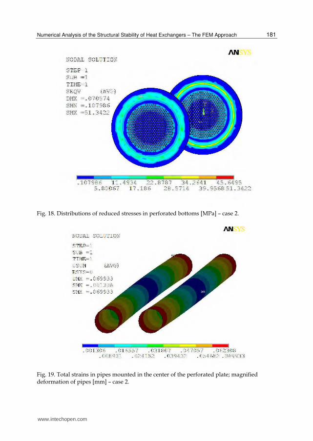
Fig. 18. Distributions of reduced stresses in perforated bottoms [MPa] – case 2.
Fig. 19. Total strains in pipes mounted in the center of the perforated plate; magnified deformation of pipes [mm] – case 2.
www.intechopen.com

Heat Exchangers – Basics Design Applications
182
Fig. 20. Total strains in pipes subject to the maximal strain; magnified deformation of pipes [mm] – case 2.
Fig. 21. Strain path in the pipe along its length [mm] - an example (the pipe is mounted in the position closest to the geometrical axis of the heat exchanger).
www.intechopen.com

Numerical Analysis of the Structural Stability of Heat Exchangers – The FEM Approach
183
Fig. 22. Strain path in the pipe along its length [mm] – an example (the pipe is mounted in the position farthest from the geometrical axis of the heat exchanger).
6. Analysis of the results
A shell-solid model of the heat exchanger - a water heater - was subjected to the numerical calculations. The author‘s task was to conduct a possibly full analysis of stresses and strains occurring in structural elements of the heat exchanger, especially under extreme conditions that appear during, e.g., emergency operation. The calculations were carried out for altered thickness of the plate (in the first case by 15%, in the second one by 50%). This change was dictated by economic reasons. On the basis of the calculation results and the analysis of distributions of stresses and strains, one can conclude that the perforated bottom (the perforated plate) is not the place where stresses concentrate. In the first case, the reduced stresses in the bottom were equal to approx. 30 MPa (Fig.10), and in the second case they increased to approx. 50 MPa (Fig.18). The analysis of local zones of stresses in the whole heat exchanger has allowed us to find out that the maximal stresses in both cases appeared in the connections between the collar with the jacket and they were equal to, respectively, 198MPa, and in the second case they increased by approx. 10%. As opposed to the values of stresses, the total strains differ considerably. The maximal strains occurring in the heat exchanger were of the magnitude of 0.07 mm in the first case (Fig.5), whereas in the second case they increased up to 4.45 mm (Fig.13). Some exemplary maps of strains in the selected pipes mounted, correspondingly:
1. in the central part of the perforated plate (Fig. 11 and Fig.19), 2. in the outer part of the perforated plate, in the place where the maximal deflection is
anticipated (Fig.12 and Fig. 20) have been presented in the paper.
www.intechopen.com

Heat Exchangers – Basics Design Applications
184
The analysis of the calculation results has shown that the pipes mounted in the outer part are subject to higher deformations that the pipes mounted inside the central part of the plate that are subject more to elongation than to deflection.
In the general case, a stability loss of the elastic structure is a nonlinear problem that can
be investigated with the iterative or incremental analysis of large displacements. This
issue was dealt with by Arygyris (1977). With respect to the critical value of load, an
influence of geometrical nonlinearity remains insignificant in numerous cases. When it is
exceeded, a radical change in the configuration that corresponds to the equilibrium state
occurs. If we are interested in the value Pkr and the postcritical state, it is enough to apply
an elastic analysis. The task is not so easy in the heat exchanger under investigation. The
structure of the device is complex and loaded with pressures that follow from the
operation, therefore the FEM calculations were proposed. The investigations of the
deformation nature of the heat exchanger and the analysis of strains and displacements
are very important tasks which would allow designers to evaluate the correctness of the
structure in order to avoid considerable differences in displacements, e.g., through a
change in the connection of the perforated bottom with the jacket or an application of a
pipe compensation, etc.
The conducted here analysis of strains in individual structural elements of the heat
exchanger allows researchers to foresee the places of stress concentration. Thus, respective
changes can be introduced in order to decrease a number of failures of the
structure.
7. Conclusions
The investigations of the heat exchanger have allowed us to formulate the following conclusions:
- structural elements of the heat exchanger (perforated plates, a jacket) do not exhibit geometrical modes of buckling;
- perforated plates, a jacket and heating cartridge pipes do not show local plasticization zones either;
- pipes fixed farthest from the geometrical axis of the heat exchanger are subject to highest displacements, deflections; the dependence of displacements and the pipe length is of a nonlinear character (Fig.21);
- displacements of the pipes situated close to the geometrical axis of the heat exchanger are significantly lower; the dependence of displacements along the pipe length is linear (Fig. 22);
- the highest value of stresses was observed in the connection region of the jacket with the collar ( Fig.6 and Fig.14),
- perforated plates, an integral part of the heat exchanger, are not the place where stresses concentrate, and the stresses that occur in them are considerably lower than the maximal stresses occurring in pipes and the jacket.
The further analysis enables the following conclusions:
- pipes most distant from the geometrical axis of the heat exchanger are most prone to a stability loss,
www.intechopen.com

Numerical Analysis of the Structural Stability of Heat Exchangers – The FEM Approach
185
- a concentration of stresses occurs in the region where the jacket is connected to the collar,
- there is a possibility to decrease further the thickness of perforated plates of the heat exchanger.
The analysis of the obtained results has allowed us to observe the places that are most prone to a stability loss, where a concentration of stresses occurs and to determine possible alternations in the thickness of perforated plates (which would be justified economically).
8. References
Achtelik H., Gasiak G., Grzelak J. (2005). Strain and load carrying capacity of perforated plates under axial – symmetrical load, Oficyna Wydawnicza, Opole, Poland [in Polish] User‘s Guide ANSYS 12
Bijlaard P.P. (1950). On the plastic buckling of plates, J. Aeron. Sci., Vol.17 Chudzik A.A.( 2002). Analysis of the state of stress in perforated plates of heat exchangers,
including effects of elastic and plastic zones, PhD Dissertation [in Polish] Chudzik A.A. (2008). Preliminary analysis of inelastic buckling of the heat exchangers, Journal Of
Theoretical and Applied Mechanics, Warsaw [in Polish] Concession documentation of the Py-100-020 decarbonized water heater [in Polish] Gellin S. (1979). Effect of an axisymmetric imperfection on the plastic buckling of an axially
compressed cylindrical shell, J. Appl. Mech., Vol. 46 Gerarad G. (1956). Compressive and torsional buckling of thin-wall cylinders in the yield region,
NACA Techn. Note, No.3276 Grigoluk E.I. (1957). O vypucivanii tonkich oblocek za predelom uprugosti, Izv. AN SSSR, Otd.
Tech. N., 10 Grigoluk E.I. (1957). Cisto plasticeskaja proteja ustojcivosti tonkich oblocek, Prikl. Matem. i mech.,
21, No 6 Harding J.E., (1978). The elastic-plastic analysis of imperfect cylinders, Proc. Ins. Civ. Eng, Part 2 Hobler T. (1986), Heat Transfer and Heat Exchangers, Wydawnictwo Naukowo-Techniczne,
Warsaw [in Polish] Horak J., Lord G.J., Peletier M.A. (2005), Cylinder buckling: the mountain pass as an organizing
center, arXiv:math. AP/0507 263, 1 Hutchinson J.W. (1972). On the postbuckling behaviour of imperfection-sensitive structures in the
plastic range, J Appl. Mech., Vol.39 Hutchinson J.W. (1973). Imperfection sensitivity in the plastic range, J. Mech. Phys.Solids, Vol 21 Iljussin A.A. (1944). Ustojcivost plastinok I oblocek za predelom uprugosti, Prikl. matem. i mech.,
8, No. 5 Lee L.H.N. (1961). Inelastic buckling of cylindrical shells under axial compression and internal
pressure, Developments in Mechanics, 1 Lee L.H.N. (1962). Inelastic buckling of initially imperfect cylindrical shells subject to axial
compression, J. Aerospace Sci., Vol.29, No.1 Lee L.H.N. (1962). Inelastic buckling of cylindrical shells under axial compression and internal
pressure, w: Proc.4thU.S. Nat. Congr. Appl. Mech., Berkley, Calif. Murphy L. M., Lee L.H.N. (1971). Inelastic buckling process of axially compressed cylindrical
shells subject to edge constrains, Int. J. Solids Struct., 7,8
www.intechopen.com

Heat Exchangers – Basics Design Applications
186
Nowak Z., hyczkowski M. (1963). Survey of the latest studies on shell stability, Mechanika teoretyczna stosowana, 1,2 [in Polish]
Sobel L.H., Newman S.Z. (1982). Plastic buckling of cylindrical shells under axial compression, J. Press. Ves. Tech., 102
Królak M. et. al. (1990). Postcritical states and the limit load carrying capacity of flat-walled grinders, Państwowe Wydawnictwo Naukowe, ISBN 83-01-10377-9, Warsaw [in Polish]
Sewell M.J. (1972). A survey of plastic buckling, in: Stability, H. Leipholz, University of Waterloo Press, Ontario
Ryś J.(2003).Methodology of calculation of stresses in the perforated walls of heat exchangers,Iniynieria I aparatura chemiczna, Nr 6/2003 [in Polish]
Zielnica J. (1969). Stabilty loss in the thin-walled shell rolled out beyond the elastic limit, Zeszyty Naukowe Politechniki Poznańskiej, Mechanika 63,9 [in Polish]
www.intechopen.com

Heat Exchangers - Basics Design ApplicationsEdited by Dr. Jovan Mitrovic
ISBN 978-953-51-0278-6Hard cover, 586 pagesPublisher InTechPublished online 09, March, 2012Published in print edition March, 2012
InTech EuropeUniversity Campus STeP Ri Slavka Krautzeka 83/A 51000 Rijeka, Croatia Phone: +385 (51) 770 447 Fax: +385 (51) 686 166www.intechopen.com
InTech ChinaUnit 405, Office Block, Hotel Equatorial Shanghai No.65, Yan An Road (West), Shanghai, 200040, China
Phone: +86-21-62489820 Fax: +86-21-62489821
Selecting and bringing together matter provided by specialists, this project offers comprehensive informationon particular cases of heat exchangers. The selection was guided by actual and future demands of appliedresearch and industry, mainly focusing on the efficient use and conversion energy in changing environment.Beside the questions of thermodynamic basics, the book addresses several important issues, such asconceptions, design, operations, fouling and cleaning of heat exchangers. It includes also storage of thermalenergy and geothermal energy use, directly or by application of heat pumps. The contributions arethematically grouped in sections and the content of each section is introduced by summarising the mainobjectives of the encompassed chapters. The book is not necessarily intended to be an elementary source ofthe knowledge in the area it covers, but rather a mentor while pursuing detailed solutions of specific technicalproblems which face engineers and technicians engaged in research and development in the fields of heattransfer and heat exchangers.
How to referenceIn order to correctly reference this scholarly work, feel free to copy and paste the following:
Agnieszka A. Chudzik (2012). Numerical Analysis of the Structural Stability of Heat Exchangers – The FEMApproach, Heat Exchangers - Basics Design Applications, Dr. Jovan Mitrovic (Ed.), ISBN: 978-953-51-0278-6,InTech, Available from: http://www.intechopen.com/books/heat-exchangers-basics-design-applications/numerical-analysis-of-the-structural-stability-of-the-heat-exchanger-finite-element-method-approach

© 2012 The Author(s). Licensee IntechOpen. This is an open access articledistributed under the terms of the Creative Commons Attribution 3.0License, which permits unrestricted use, distribution, and reproduction inany medium, provided the original work is properly cited.