Behavior of eccentrically inclined loaded footing resting ...

Research ArticleNumerical Analysis of Eccentrically LoadedCold-Formed Plain Channel Columns
A. P. Nivethitha, G. Vani, and P. Jayabalan
National Institute of Technology, Tiruchirappalli 620015, India
Correspondence should be addressed to A. P. Nivethitha; [email protected]
Received 20 February 2014; Revised 20 May 2014; Accepted 26 May 2014; Published 24 June 2014
Academic Editor: Lucio Nobile
Copyright © 2014 A. P. Nivethitha et al.This is an open access article distributed under the Creative CommonsAttribution License,which permits unrestricted use, distribution, and reproduction in any medium, provided the original work is properly cited.
Finite element analysis of pinned cold-formed plain channel columns of different width-to-thickness ratios is presented in thispaper. The study is focused not only on axially loaded columns, but also on eccentrically loaded columns. The general purposefinite element softwareABAQUS6.12was used, and the force controlled loadingwas adopted.Geometric andmaterial nonlinearitieswere incorporated in the finite element model. The ultimate loads are compared with the direct strength method (DSM) for axiallyloaded columns. Also, a parametric study is done by varying the length of the column and width of the unstiffened element. It isobserved that the results correlate better with the DSM values for columns having unstiffened elements of lower 𝑏𝑓/𝑡 ratios. Thechange in ultimate load is studied only in ABAQUS, as the position of load moves towards the free edge and the supported edge ofthe unstiffened element. A parametric study is done by varying the nonuniform compression factor for the columns. It is observedthat the ultimate load increases as the position of load moves towards the supported edge and it is influenced by the 𝑏𝑓/𝑡 ratio ofthe unstiffened element.
1. Introduction
There are two main categories of steel structural members,namely, hot-rolled and cold-formed sections. Hot-rolledsections are quite familiar. Cold-formed steel sections havebeen used in car bodies, railway coaches, equipment, trans-mission towers, and so forth. Their application as structuralmembers is the prime interest of ongoing research. Cold-formedmembers are generally known for their thin elements,buckling behaviour, and postbuckling strength. They havehigh strength-to-weight ratio and a thickness as small as0.5mm can be achieved. In the cold-formed family, manyconfigurations such as angle, channel, I, Z, sigma, T, and tubescan be produced. Some of them are entirely composed ofstiffened elements or unstiffened elements or a combinationof both. Owing to the existence of such elements, each sectionbehaves in its own way. This paper has focused on thebehaviour of plain channel sections. Plain channel membersare generally used as wall studs, rafters, truss members,and floor joists. In North America, channels have beencategorised as S members which are lipped channels, mostoften used for wall studs, floor joists, and ceiling or roof
rafters, T members which are unlipped channels, used fortop and bottom plates (tracks) in walls and rim joists in floorsystems, and U members which are again unlipped channelsbut have a smaller depth than tracks and are used to bracemembers, as well as for ceiling support systems.
Kalyanaraman and Ramakrishna [1]developed a proce-dure for calculating the buckling and postbuckling strengthof stiffened elements subjected to nonuniform compression.An effective width equation was proposed similar to thatgiven by Winter for uniformly compressed elements, butit was applicable to the entire range of stress gradientstarting from uniform compression to uniform bending. Theresults were compared with those obtained from experimentsconducted on nonuniformly compressed webs in beams andeccentrically loaded columns. Kalyanaraman and Jayabalan[2] presented an analytical procedure for calculating thelocal buckling strength based on which the equations wereproposed for the local buckling stress of nonuniformlycompressed stiffened and unstiffened elements. The resultswere compared with experimental values. El-Sheikh et al. [3]described the behavior of stiffened and unstiffened channelmembers. The section properties and the effect of the use
Hindawi Publishing CorporationJournal of StructuresVolume 2014, Article ID 908415, 10 pageshttp://dx.doi.org/10.1155/2014/908415

2 Journal of Structures
of stiffeners were discussed, and structural performancewas assessed according to British Standard SpecificationsBS5950. A wider parametric study was made for channelmembers with various aspect ratios, stiffeners’ sizes, andslenderness ratios. The results revealed how the memberscould be profiled to obtain the optimum performance invarious applications.
Schafer et al. [4] provided an overview of computationalmodelling, both elastic buckling and nonlinear collapse anal-ysis, for cold-formed steel members. Tools like CUFSM andABAQUS were used, and issues such as how to fully comparefinite strip and finite element solutions were elaborated withexamples.The importance of imperfections, residual stresses,material modelling, boundary conditions, element choice,element discretization, and solution controls in collapsemodelling of cold-formed steel were also highlighted.
Young and Yan [5, 6] developed nonlinear finite ele-ment models for lipped and plain channel sections, whereingeometrical and material nonlinearities were included andverified against fixed ended channel column tests. Anextensive parametric study of cross-section geometries wasmade. The column strengths obtained were compared to thedesign column strengths calculated using the American, Aus-tralian/New Zealand, and European specifications for cold-formed steel structures. It was shown that the design columnstrengths calculated from the three specifications were gen-erally conservative. Young and Rasmussen [7] presented anexperimental investigation into the plain and lipped channelsections for both fixed ended and pin ended conditions. Forplain channel columns, the difference in strength caused bythe effect of local buckling was the greatest at short andintermediate lengths where the strength is influenced by localbuckling. Nguyen and Kim [8] studied the buckling of thin-walled composite columns in hat sections and lipped channelsections reinforced with web stiffener. The columns werecomposed of symmetric angle-ply laminates. The finite ele-ment method was used to investigate the buckling behaviorof the columns. Rigid body constraints were applied at theends through reference nodes and a compressive force wasapplied to it. Bifurcation analyses were carried out to obtainthe buckling load and mode shapes of the columns. Load-deflection analyses were performed to study the postbucklingbehavior of the columns.
Wang et al. [9] studied cold-formed steel columns withthree different sections and eleven different eccentricitiesunder eccentric compression loading by using ANSYS. It wasshown that the maximum of ultimate load-carrying capacityappearedwhen effective eccentricitywas 0mmanddecreasedwith the increase of the value of effective eccentricity. Webstiffening could improve load-carrying capacity when theeccentricity was near the web side.
Miller and Pekoz [10] studied the effects of load eccentric-ity on cold-formed lipped channel sections through experi-ments on long columns.The effects of perforations on thewebwere also studied. It was concluded that the axial strengthsof the columns were sensitive to an eccentricity as smallas 2.5mm. Conservative strength predictions were obtainedwith AISI predictions, including the load eccentricity effectsand perforations modelled using unstiffened strip method.
Rhodes et al. [11] performed a series of compressiontests on cold-formed stainless steel lipped channel columns.The cross-section dimensions, the column length, and theeccentricity of the load were varied and the results obtainedwere compared with those obtained from the relevant designspecifications in America and in Europe. It was concludedthat Eurocode provisions were accurate for concentricallyloaded fully effective sections and conservative for eccen-trically loaded columns. For concentrically loaded columns,the design codes were accurate in their predictions of thebuckling loads for all but the lowest slenderness ratiosexamined. In this range, the ASCE predictions were moreconservative than the Eurocode. Dejin and Shaofan [12]performed numerical analysis on eccentrically loaded singlysymmetric open section columns. A simple method wasproposed through which torsional-flexural buckling loadscould be predicted very close to the test values. An empiricalrelation to determine the torsional-flexural buckling loadwasdeveloped based on a parametric study on hat sections. But itwas too conservative for other open sections.
Schafer [13] provided a review of the direct strengthmethod (DSM) of cold-formed steel design.The equations forthe design of columns and beamswere provided in an excerptfrom the North American Specification. A brief comparisonwith effective width method was provided. Current andongoing research to extend the DSM was reviewed andreferences were provided. Schafer and Adany [14] showedthe derivation of conventional finite strip method (FSM)analysis identical to that employed in CUFSM, from the firstprincipals. An example of a lipped channel was provided forbasic understanding. Thus, it was shown that constrainedfinite stripmethod (cFSM) combined with conventional FSMprovides a powerful tool for understanding the cross-sectionstability.
Thus, it is clear that most of the papers are focusedon the behaviour of cold-formed sections subjected to purecompression.Only limited researches have beenmade on sec-tions subjected to nonuniform compression. Though earlierstudies are made on axially loaded columns, achieving such acondition in reality becomes an ideal case. Nonuniform com-pression may result due to misalignment of columns, eccen-tricity of loading, or webs of beams subjected to moments.Hence, the objective of the present study is to develop finiteelement models for both axially loaded and eccentricallyloaded columns and carry out parametric studies by varyingthe effective length, flat width ratio of unstiffened element,and nonuniform compression factor. DSM equations are alsoapplied and results are compared with FEM results for axiallyloaded columns only. Determining the nominal strength foreccentrically loaded columns using DSM is beyond the scopeof this paper.
2. Finite Element Modelling
2.1. General. Finite element software ABAQUS version 6.12was used for modelling the cold-formed steel channelcolumns. The section dimensions were taken from the thesisby Jayabalan [15]. The rounded corners were also modelled.

Journal of Structures 3
R
Bw
Bf
Figure 1: Section parameters for plain channel.
Figure 2: First buckling mode (local buckling) of column C1 ofeffective length 600mm.
Table 1: Cross-section dimensions for plain channel.
Column number 𝐵𝑓
(mm)𝐵𝑤
(mm)𝑅
(mm)𝑡
(mm) 𝑏𝑓/𝑡 𝑏𝑤/𝑡
C1 96.80 50.00 6.00 1.94 45.8 17.59C2 120.30 56.80 6.00 1.73 65.07 23.90C3 59.40 61.00 5.50 1.73 30.16 26.90C4 184.40 53.10 6.50 2.09 84.12 17.19
For the transfer of load, rigid plates were also modelled at thetop and bottom.The section parameters defined in Table 1 areshown in Figure 1.
Initially, an eigenvalue buckling analysis was done toestablish the buckling modes. In the next stage, a nonlinearanalysis was performed using STATIC RIKS by introducinggeometric and material nonlinearity. A scale factor of 0.2times the thickness of the section [15] was adopted to intro-duce imperfection in the first buckling mode by using thekeyword ∗IMPERFECTION fromABAQUS library. A typical
first bucklingmode for columnC1 of effective length 600mmis shown in Figure 2.
2.2. Material Modelling. The material assigned was con-sidered as isotropic and homogenous. In ABAQUS, whiledefining the material property, the nominal stress and strainvalues were converted to true stress and logarithmic plasticstrain using the following:
𝜎true = 𝜎nom (1 + 𝜀nom) ,
𝜀pl= ln (1 + 𝜀nom) −
𝜎true𝐸
.
(1)
In the present study, the stress-strain plot was consideredas bilinear. The following material properties were adoptedfor a thickness of 2mm:
Young’s modulus, 𝐸 = 209GPa,
Poisson’s ratio, 𝜇 = 0.3,
yield stress, 𝑓𝑦 = 450MPa,
ultimate stress, 𝑓𝑢 = 550MPa,
strain corresponding to ultimate stress, 𝜀 = 10%.
2.3. Element Type Meshing and Assembly. The channels weremodelled using shell element. S4R5 element type was chosen.S4R5 is a 4-node doubly curved thin shell element, reducedintegration, hourglass control, using 5 degrees of freedomper node. The end plates were modelled with 3D4 elements,that is, a 4-node 3D rigid quadrilateral element. A meshconvergence studywasmade and a suitablemesh size of 5mm× 5mm was chosen.
The rigid plates were assembled such that their centroidseither coincide with the centroid of the cross-section ormoveaway from it so that axially loaded and eccentrically loadedconditions are achieved, respectively. A typical column forboth of the cases is shown in Figures 3 and 4, respectively.
2.4. Contact Pair Definition. A contact pair was definedbetween the rigid plates and the channel section edges for thetransfer of load. A node to surface contact was defined in bothtangential and normal directions. Hard contact was definedin the normal direction to ensure that there is no penetrationof the edges and plate. A friction ratio was defined in thetangential direction to prevent sliding between plates and thecolumn.
2.5. Loading and Boundary Conditions. The columns wereanalysed for pinned-pinned boundary conditions, whichwas achieved by restraining all the translational degrees offreedom at both of the edges of channel sections except thetranslational degree of freedom in the axial direction at thetop end. Force controlled loading was adopted by applyingpressure load on the top plate. The corresponding details areshown in Figure 5.

4 Journal of Structures
Rigid plate located at the centroid of the section RP-2
RP-1
Figure 3: Axially loaded column.
Centroid of the section
Rigid plate located awayfrom the centroid of
the section RP-2
RP-1
Figure 4: Eccentrically loaded column.
2.6. Validation. Nonlinear finite element model was devel-oped for a plain channel section by using the input fromYoung and Yan [6].
A series of fixed ended plain cold-formed channel sec-tions were modelled and analysed. Since the finite elementmodel was overestimating the experimental values, whichcould be probably due to the small values of residual stressesand the rounded corners of the sections that were ignoredin the FEM, a column strength equation was proposed as afunction of the effective length and the ultimate load fromfinite element modelling as in the following:
𝑃∗FEA = (0.95 − 0.02𝐿) 𝑃FEA, (2)
where 𝐿 = effective length in m.The comparison of the current study and the available
results is shown in Figure 6.
2.7. Nonuniform Compression Factor, 𝛼. A nonuniform com-pression factor was defined in terms of the stresses at theedges of the unstiffened element as follows:
𝛼 = 1 −𝜎min𝜎max
. (3)
Two cases were considered: maximum compression at freeedge (𝐹) and maximum compression at supported edge (𝑆).The unsupported edge of the unstiffened element is taken asthe free edge and the other edge which is supported by thestiffened element is taken as the supported edge.Three valueswere considered for 𝛼 (0, 0.5, and 1).The description for thesevalues is given in Table 2. The positions of load for variousvalues of 𝛼 are shown in Figures 7(a), 7(b), and 7(c).
3. CUFSM and Direct Strength Method
3.1. General. The two important methods available for thedesign of cold-formed members are the effective widthmethod (EWM) and the direct strength method (DSM). Theresults obtained from finite element modelling for axiallyloaded columns were compared with DSM results.
3.2. Direct Strength Method. The direct strength method is anew design method which was adopted in 2004 as Appendix1 to the North American Specification for the Design ofCold-Formed Steel Structural Members.Themost importantadvantages of using DSM are the following: (1) effectivewidths need not be calculated, (2) gross properties of thesections are used, (3) iterations for the determination ofmember design strength are not required, and (4) interac-tion of elements in local buckling is considered. In DSM,the elastic buckling loads in local, distortional, and globalbuckling and that which causes first yield are determinedand employed in a series of equations to directly provide thestrength prediction. DSM is extensively developed for beamsand columns only.
The nominal axial strength 𝑃𝑛 is the minimum of 𝑃ne, 𝑃nl,and 𝑃nd as given below. These equations are applicable forcolumns subjected to pure compression only.
3.2.1. Flexural, Torsional, or Flexural-Torsional Buckling. Thenominal axial strength 𝑃ne, for flexural, torsional, or flexural-torsional buckling, is shown as follows:
𝑃ne = (0.658𝜆2𝑐) 𝑃𝑦 for 𝜆𝑐 ≤ 1.5,
𝑃ne = (0.877
𝜆2𝑐
)𝑃𝑦 for 𝜆𝑐 > 1.5,
where 𝜆𝑐 = √𝑃cr𝑃𝑦
,
𝑃𝑦 = 𝐴𝑔𝐹𝑦.
(4)

Journal of Structures 5
Ux = 0,Uy = 0,
Uz = 0
Ux = 0,Uy = 0
Contact pair-hard (normal) and friction
X
Y
Z
ratio (tangential)Pressure load
the plateapplied on
RP-2
RP-2
RP-1RP-1
Figure 5: Details of the model.
3.2.2. Local Buckling. Thenominal axial strength𝑃nl, for localbuckling, is shown as follows:
𝑃nl = 𝑃ne for 𝜆l ≤ 0.776,
𝑃nl = 𝑃ne [1 − 0.15(𝑃crl𝑃ne
)
0.4
](𝑃crl𝑃ne
)
0.4
for 𝜆l > 0.776,
where 𝜆l = √𝑃ne𝑃crl
.
(5)
3.2.3. Distortional Buckling. The nominal axial strength 𝑃nd,for distortional buckling, is shown as follows:
𝑃nd = 𝑃𝑦 for 𝜆𝑑 ≤ 0.561,
𝑃nd = 𝑃𝑦 [1 − 0.25(𝑃crd𝑃𝑦
)
0.6
](𝑃crd𝑃𝑦
)
0.6
for 𝜆d > 0.561,
where 𝜆𝑑 = √𝑃𝑦
𝑃crd.
(6)
3.3. CUFSM. CUFSM is a software program which isfreely available for exploring elastic buckling behaviour ofthin-walled members. It helps in calculating the bucklingstress and buckling modes of various sections. Initially,it was developed only for simply supported conditions.Later, it was developed for other boundary conditions suchas clamped-clamped, simple-clamped, clamped-free, andclamped-guided. The following points help in better under-standing the necessity of using CUFSM.
(1) Design and hand methods that are traditionally usedfor plate structures often ignore the compatibility at
Table 2: Nonuniform compression factor.
𝛼 Description0 Uniform compression0.5 𝜎min = 0.5 ∗ 𝜎max
1 𝜎min = 0
plate junctures and typically provide no means tocalculate a variety of buckling modes.
(2) CUFSM allows all elastic buckling modes of a struc-ture to be quantified and examined.
(3) In order to calculate input for DSM (say 𝑃cre, 𝑃crl, and𝑃crd for compression members), CUFSM can be usedinstead of cumbersome hand calculations, therebysaving time.
3.4. Application of CUFSM and DSM for Plain ChannelColumns. In plain channel columns, there is no distortionalbuckling due to the absence of edge or intermediate stiffeners.Hence, in CUFSM, the plain channels sections weremodelledand analysed for simply supported conditions, and load factorwas obtained for global and local buckling modes. The loadfactor is the ratio of elastic buckling load to the first yieldload from which 𝑃cr was determined for each of the twobuckling modes. These values were then employed in (4) to(5). The minimum of the nominal strengths in global andlocal buckling modes was taken as the nominal axial strengthof the column subjected to pure compression.
4. Results and Discussion
4.1. Influence of Effective Length. Each of the columns wasanalysed for four effective lengths (300, 600, 900, and1200mm). The elastic buckling loads and ultimate loads aretabulated in Table 3 for axially loaded condition.

6 Journal of Structures
Table 3: Influence of effective length on axially loaded columns C1 to C4.
Column number 𝐿 𝑒 (mm) 𝐿 𝑒/𝑟minElastic buckling load, 𝑃cr (kN) Ultimate load, 𝑃𝑢 (kN)
ABAQUS CUFSM ABAQUS/CUFSM ABAQUS DSM ABAQUS/DSM
C1
300 13.48 36.53 35.00 1.04 52.46 84.63 0.62600 26.96 34.54 33.04 1.05 50.05 63.84 0.78900 40.44 34.35 33.11 1.04 48.81 42.52 1.151200 53.92 34.27 33.04 1.04 48.54 30.00 1.62
C2
300 11.69 21.04 20.31 1.04 38.73 75.00 0.52600 23.38 20.13 19.67 1.02 28.36 60.33 0.47900 35.06 19.69 19.19 1.03 32.86 42.62 0.771200 46.75 19.64 19.16 1.03 33.36 29.85 1.12
C3
300 11.60 43.92 41.95 1.05 54.25 70.62 0.77600 23.20 42.86 41.62 1.03 49.73 58.95 0.84900 34.80 42.45 41.33 1.03 49.12 44.66 1.101200 46.40 42.24 41.32 1.02 45.83 32.33 1.42
C4
300 12.30 22.69 22.34 1.02 55.19 107.9 0.51600 24.60 22.78 22.34 1.02 43.41 84.59 0.51900 36.90 22.78 22.34 1.02 41.10 56.91 0.721200 49.20 22.72 22.34 1.02 40.19 39.82 1.01
0102030405060708090
0.00 0.50 1.00 1.50 2.00 2.50 3.00 3.50
Prop
osed
colu
mn
stren
gth
(kN
)
Effective length about minor axis (m)
Present studyAvailable results
Figure 6: Validation.
It could be seen that the elastic buckling loads obtainedfrom ABAQUS were higher than those from CUFSM. Amaximum variation of 4.3% was evident. On average, thevariation lies in the range of 1.8% to 4%. The variation inresults ismainly because rounded corners are notmodelled inCUFSM. Also, themesh size in both of the software programsplays an important role.
Though the elastic buckling loads from ABAQUS andCUFSM were nearly the same for almost all cases, forcolumns of higher 𝑏𝑓/𝑡 ratios, the results are in betteragreement and the elastic buckling load was constant as theeffective length increased. Based on the similarities in elasticbuckling loads fromABAQUS and CUFSM, it was concludedthat the modelling parameters adopted in ABAQUS are in
Table 4: Influence of 𝑏𝑓/𝑡 ratio for axially loaded columns.
Column number 𝑏𝑓/𝑡 FEM (kN) DSM (kN) FEM/DSMC2-BF-34.60 15.53 62.07 57.19 1.09C2-BF-56.80 28.36 50.22 60.33 0.83C2-BF-69.20 35.53 47.68 61.70 0.77C2-BF-86.50 45.53 42.07 62.93 0.67C2-BF-103.80 55.53 37.77 64.95 0.58C2-BF-121.10 65.53 35.10 65.54 0.54C2-BF-138.40 75.53 32.48 66.88 0.49
good correlation and could be used for other parametricstudies as well.
With regard to ultimate load, the results from ABAQUSand DSM were equivalent for only one length for all thefour columns. Load displacement plots obtained for aneffective length of 600mm are shown in Figure 8. The resultsconverged better for all lengths of column C3 (lower 𝑏𝑓/𝑡ratio) compared to other columns.
4.2. Influence of 𝑏𝑓/𝑡 Ratio. The width of the unstiffenedelementwas alone varied in columnC2, for an effective lengthof 500mm with other parameters maintained constant. Thecolumn name “C2-BF-34.60” represents column C2 havingwidth of the unstiffened element changed to 34.60mm. Thecolumns were analysed under axially loaded condition. Theultimate loads obtained from ABAQUS were compared withDSM results. The results are given in Table 4. The resultsconverged better for columns with lower 𝑏𝑓/𝑡 ratios.
4.3. Influence of Nonuniform Compression Factor. All thecolumns of different lengths were analysed in ABAQUS for

Journal of Structures 7
Force at centroid
(a)
Position of force
Centroid
(b)
Position of force
Centroid
(c)
Figure 7: Position of force for (a) 𝛼 = 0, (b) maximum compression at free edge, and (c) maximum compression at supported edge.
three values of nonuniform compression factor (0, 0.5, and1) considering both of the cases of maximum compression atfree edge and supported edge.
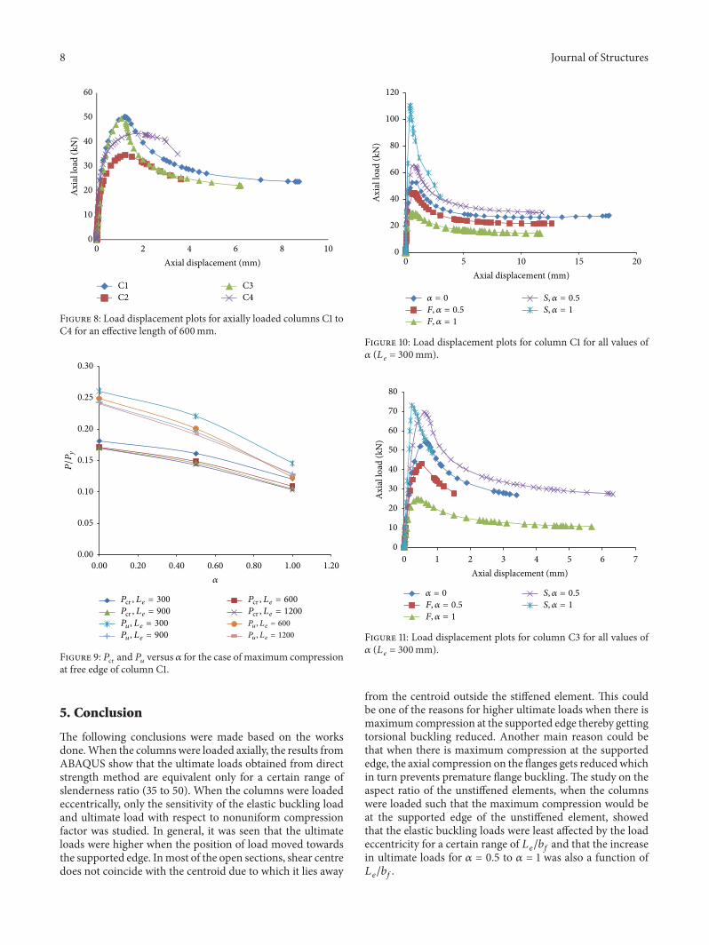
The ultimate load was higher for the case of maximumcompression at supported edge than at free edge. Consideringthe case of maximum compression at free edge, the ultimateload and elastic buckling load decreased as the slendernessratio increased, for any value of 𝛼, and decreased as 𝛼
increased, for any effective length. The variation of 𝑃cr and𝑃𝑢 with respect to 𝛼 for the case of maximum compression atfree edge of column C1 is shown in Figure 9.
Under the case of maximum compression at supportededge, the ultimate load increased as 𝛼 increased but there wasa steep increase of ultimate load when 𝛼 increased from 0.5to 1 for columns of higher 𝑏𝑓/𝑡 ratio. The load displacementplots for columns C1 and C3 for all 𝛼 values for both of thecases are shown in Figures 10 and 11, respectively (𝐹: maxi-mum compression at free edge, 𝑆: maximum compression atsupported edge).
It was observed that the aspect ratio of the unstiffenedelement had a significant influence on the variation of elasticbuckling loads with respect to 𝛼, when there was maximumcompression at the supported edge. The variation of elasticbuckling loads with respect to 𝛼 is presented in Figure 12.
4.4. Influence of Aspect Ratio (Effective Length/Flat Width)of Unstiffened Element. In column C3, the width of theunstiffened element alone was varied such that the width-to-thickness ratio ranges from 30 to 80, with an effectivelength of 300mm. The columns were analysed in ABAQUSfor all three nonuniform compression factors under the caseof maximum compression at supported edge. The influenceof 𝛼 on the elastic buckling loads reduced and the ultimateloads increased drastically when 𝛼 increased from 0.5 to 1,for an aspect ratio of unstiffened elements in the range of2.5 to 4.5. The corresponding plots are shown in Figures 13and 14, respectively.
8 Journal of Structures
0
10
20
30
40
50
60
0 2 4 6 8 10
Axi
al lo
ad (k
N)
Axial displacement (mm)
C1C2
C3C4
Figure 8: Load displacement plots for axially loaded columns C1 toC4 for an effective length of 600mm.
0.00
0.05
0.10
0.15
0.20
0.25
0.30
0.00 0.20 0.40 0.60 0.80 1.00 1.20
P/P
y
𝛼
Pu, Le = 300 Pu, Le = 600
Pu, Le = 900 Pu, Le = 1200
Pcr , Le = 300 Pcr , Le = 600
Pcr , Le = 900 Pcr , Le = 1200
Figure 9: 𝑃cr and 𝑃𝑢 versus 𝛼 for the case of maximum compressionat free edge of column C1.
5. Conclusion
The following conclusions were made based on the worksdone.When the columnswere loaded axially, the results fromABAQUS show that the ultimate loads obtained from directstrength method are equivalent only for a certain range ofslenderness ratio (35 to 50). When the columns were loadedeccentrically, only the sensitivity of the elastic buckling loadand ultimate load with respect to nonuniform compressionfactor was studied. In general, it was seen that the ultimateloads were higher when the position of load moved towardsthe supported edge. Inmost of the open sections, shear centredoes not coincide with the centroid due to which it lies away
0
20
40
60
80
100
120
0 5 10 15 20
Axi
al lo
ad (k
N)
Axial displacement (mm)
𝛼 = 0
F, 𝛼 = 0.5
F, 𝛼 = 1
S, 𝛼 = 0.5
S, 𝛼 = 1
Figure 10: Load displacement plots for column C1 for all values of𝛼 (𝐿 𝑒 = 300mm).
0
10
20
30
40
50
60
70
80
0 1 2 3 4 5 6 7
Axi
al lo
ad (k
N)
Axial displacement (mm)
𝛼 = 0
F, 𝛼 = 0.5
F, 𝛼 = 1
S, 𝛼 = 0.5
S, 𝛼 = 1
Figure 11: Load displacement plots for column C3 for all values of𝛼 (𝐿 𝑒 = 300mm).
from the centroid outside the stiffened element. This couldbe one of the reasons for higher ultimate loads when there ismaximum compression at the supported edge thereby gettingtorsional buckling reduced. Another main reason could bethat when there is maximum compression at the supportededge, the axial compression on the flanges gets reducedwhichin turn prevents premature flange buckling. The study on theaspect ratio of the unstiffened elements, when the columnswere loaded such that the maximum compression would beat the supported edge of the unstiffened element, showedthat the elastic buckling loads were least affected by the loadeccentricity for a certain range of 𝐿𝑒/𝑏𝑓 and that the increasein ultimate loads for 𝛼 = 0.5 to 𝛼 = 1 was also a function of𝐿𝑒/𝑏𝑓.

Journal of Structures 9
0.000.050.100.150.200.250.300.350.40
0.00 0.20 0.40 0.60 0.80 1.00 1.20
S, C1-300S, C1-600S, C1-900S, C1-1200S, C2-300S, C2-600S, C2-900S, C2-1200
S, C3-300S, C3-600S, C3-900S, C3-1200S, C4-300S, C4-600S, C4-900S, C4-1200
𝛼
Pcr/P
y
Figure 12: Variation of elastic buckling load with respect tononuniform compression factor for all the columns (maximumcompression at supported edge).
0.00
0.05
0.10
0.15
0.20
0.25
0.30
0.35
0.40
0.00 1.00 2.00 3.00 4.00 5.00 6.00 7.00Le/b of unstiffened element
𝛼 = 0
𝛼 = 0.5
𝛼 = 1
Pcr/P
y
Figure 13: Influence of the aspect ratio of the unstiffened elementon the elastic buckling load when maximum compression is atsupported edge.
Nomenclature
𝐴𝑔: Gross area of the section𝐵𝑓: Width of the unstiffened element (flange)𝐵𝑤: Width of the stiffened element (web)𝑏𝑓: Flat width of unstiffened element (flange)𝑏𝑤: Flat width of stiffened element (web)𝑡: Thickness of the section𝑅: Inner radius of the section𝜎min: Minimum stress at one edge of the
unstiffened element
0.00
0.10
0.20
0.30
0.40
0.50
0.60
0.00 1.00 2.00 3.00 4.00 5.00 6.00 7.00Le/b of unstiffened element
𝛼 = 0
𝛼 = 0.5
𝛼 = 1
Pu/P
y
Figure 14: Influence of the aspect ratio of the unstiffened elementon the ultimate load when maximum compression is at supportededge.
𝜎max: Maximum stress at the other edge of theunstiffened element
𝜎true: True stress𝜎nom: Nominal stress𝜀nom: Nominal strain𝜀pl: Logarithmic plastic strain𝛼: Nonuniform compression factor𝜇: Poisson’s ratio𝐸: Young’s modulus𝑓𝑦: Yield stress𝑓𝑢: Ultimate stress𝑃cr: Elastic buckling load𝑃𝑦: First yield load𝑃𝑢: Ultimate load𝑃crl: Critical elastic local column buckling load𝑃cre: Minimum of the critical elastic column
buckling load in flexural, torsional, orflexural-torsional buckling
𝑃crd: Critical elastic distortional columnbuckling load
𝑃ne: Nominal axial strength for flexural,torsional, or flexural-torsional buckling
𝑃nl: Nominal axial strength for local buckling𝑃nd: Nominal axial strength for distortional
buckling𝑃𝑛: Nominal axial strength of the column𝑃∗FEA: Proposed column strength𝑃FEA: Ultimate load obtained from ABAQUS𝐿𝑒: Effective length of the column𝑟min: Minimum radius of gyration.
Conflict of Interests
The authors declare that there is no conflict of interestsregarding the publication of this paper.

10 Journal of Structures
References
[1] V. Kalyanaraman and P. Ramakrishna, “Non-uniformly com-pressed stiffened elements,” in Proceedings of the 7th Interna-tional Specialty Conference on Cold-Formed Steel Structures, St.Louis, Mo, USA, 1984.
[2] V. Kalyanaraman and P. Jayabalan, “Local buckling of stiffenedand unstiffened elements under nonuniform compression,” inProceedings of the 12th International Specialty Conference onCold-Formed Steel Structures: Recent Research and Develop-ments in Cold-Formed Steel Design and Construction, pp. 1–9,St. Loutis, Mo, USA, October 1994.
[3] A. I. El-Sheikh, E. M. A. El-Kassas, and R. I. Mackie, “Per-formance of stiffened and unstiffened cold-formed channelmembers in axial compression,” Engineering Structures, vol. 23,no. 10, pp. 1221–1231, 2001.
[4] B. W. Schafer, Z. Li, and C. D. Moen, “Computational modelingof cold-formed steel,” Thin-Walled Structures, vol. 48, no. 10-11,pp. 752–762, 2010.
[5] B. Young and J. Yan, “Channel columns undergoing local,distortional, and overall buckling,” Journal of Structural Engi-neering, vol. 128, no. 6, pp. 728–736, 2002.
[6] B. Young and J. Yan, “Finite element analysis and design of fixed-ended plain channel columns,” Finite Elements in Analysis andDesign, vol. 38, no. 6, pp. 549–566, 2002.
[7] B. Young and K. J. R. Rasmussen, “Behaviour of cold-formedsingly symmetric columns,”Thin-Walled Structures, vol. 33, no.2, pp. 83–102, 1999.
[8] H. T. Nguyen and S. E. Kim, “Buckling of composite columns oflipped-channel and hat sectionswithweb stiffener,”Thin-WalledStructures, vol. 47, no. 11, pp. 1149–1160, 2009.
[9] C. G.Wang, Z. F. Xu, Z. N. Zhang, and Y. F. Cao, “Load-carryingcapacity of cold-formed steel columns with complicated sectionunder eccentric compression loading,” Advanced MaterialsResearch, vol. 838–841, pp. 601–604, 2013.
[10] T. H. Miller and T. Pekoz, “Load-eccentricity effects on cold-formed steel lipped-channel columns,” Journal of StructuralEngineering, vol. 120, no. 3, pp. 805–823, 1994.
[11] J. Rhodes, M. Macdonald, and W. McNiff, “Buckling of coldformed stainless steel columns under concentric and eccentricloading,” in Proceedings of the 15th International Specialty Con-ference on Cold-Formed Steel Structures: Recent Research andDevelopments in Cold-Formed Steel Design and Construction,pp. 687–699, St. Louis, Mo, USA, October 2000.
[12] J. Dejin and C. Shaofan, “Inelastic torsional-flexural buckling ofcold-formed open sections under eccentric load,” in Proceedingsof the 7th International Specialty Conference on Cold-FormedSteel Structures, St. Louis, Mo, USA, 1984.
[13] B. W. Schafer, “Review: The Direct Strength Method of cold-formed steel member design,” Journal of Constructional SteelResearch, vol. 64, no. 7-8, pp. 766–778, 2008.
[14] B. W. Schafer and S. Adany, “Buckling analysis of cold-formedsteel members using CUFSM: conventional and constrainedfinite strip methods,” in Proceedings of the 18th InternationalSpecialty Conference on Cold-Formed Steel Structures: RecentResearch and Developments in Cold-Formed Steel Design andConstruction, pp. 39–54, October 2006.
[15] P. Jayabalan, Behaviour of non uniformly compressed thin unstiff-ened elements [Ph.D. thesis], Deptartment of Civil Engineering,India Institute of Technology Madras, 1989.

International Journal of
AerospaceEngineeringHindawi Publishing Corporationhttp://www.hindawi.com Volume 2014
RoboticsJournal of
Hindawi Publishing Corporationhttp://www.hindawi.com Volume 2014
Hindawi Publishing Corporationhttp://www.hindawi.com Volume 2014
Active and Passive Electronic Components
Control Scienceand Engineering
Journal of
Hindawi Publishing Corporationhttp://www.hindawi.com Volume 2014
International Journal of
RotatingMachinery
Hindawi Publishing Corporationhttp://www.hindawi.com Volume 2014
Hindawi Publishing Corporation http://www.hindawi.com
Journal ofEngineeringVolume 2014
Submit your manuscripts athttp://www.hindawi.com
VLSI Design
Hindawi Publishing Corporationhttp://www.hindawi.com Volume 2014
Hindawi Publishing Corporationhttp://www.hindawi.com Volume 2014
Shock and Vibration
Hindawi Publishing Corporationhttp://www.hindawi.com Volume 2014
Civil EngineeringAdvances in
Acoustics and VibrationAdvances in
Hindawi Publishing Corporationhttp://www.hindawi.com Volume 2014
Hindawi Publishing Corporationhttp://www.hindawi.com Volume 2014
Electrical and Computer Engineering
Journal of
Advances inOptoElectronics
Hindawi Publishing Corporation http://www.hindawi.com
Volume 2014
The Scientific World JournalHindawi Publishing Corporation http://www.hindawi.com Volume 2014
SensorsJournal of
Hindawi Publishing Corporationhttp://www.hindawi.com Volume 2014
Modelling & Simulation in EngineeringHindawi Publishing Corporation http://www.hindawi.com Volume 2014
Hindawi Publishing Corporationhttp://www.hindawi.com Volume 2014
Chemical EngineeringInternational Journal of Antennas and
Propagation
International Journal of
Hindawi Publishing Corporationhttp://www.hindawi.com Volume 2014
Hindawi Publishing Corporationhttp://www.hindawi.com Volume 2014
Navigation and Observation
International Journal of
Hindawi Publishing Corporationhttp://www.hindawi.com Volume 2014
DistributedSensor Networks
International Journal of