Numerical analysis of dynamic electroosmotic flows of non ...Numerical analyses of transient...
33
1 Numerical analysis of dynamic electro-osmotic flows of non-Newtonian fluids in rectangular microchannels Cunlu Zhao * and Chun Yang School of Mechanical and Aerospace Engineering, Nanyang Technological University 50 Nanyang Avenue, 639798, Republic of Singapore Address correspondence to this author. E-mail: [email protected] Abstract Numerical analyses of transient electro-osmosis of a typical non-Newtonian liquid induced by DC and AC electric fields in a rectangular microchannel are conducted in the framework of continuum fluid mechanics. The famous power-law constitutive model is used to express the fluid dynamic viscosity in terms of the velocity gradient. Transient start-up characteristics of electro-osmotic power-law liquid flow in rectangular microchannels are simulated by using finite element method. Under a DC electric field, it is found out and the fluid is more inert to the external electric field and the steady-state velocity profile becomes more plug-like with decrease of the flow behavior index of the power-law liquids. The numerical calculations also confirm the validity of the generalized Smoluchowski slip velocity which can serve as the counterpart for the classic Smoluchowski slip velocity when dealing with electrokinetic flow of non-Newtonian power-law fluids. Under AC electric fields, the fluid is more obviously accelerated during oscillations and the amplitude of the oscillating velocity is closer to the magnitude of the generalized Smoluchowski velocity as the fluid behavior index increases. These dynamic predictions are of practical significance for the design of microfluidic devices that
Transcript of Numerical analysis of dynamic electroosmotic flows of non ...Numerical analyses of transient...
1
Numerical analysis of dynamic electro-osmotic flows of
non-Newtonian fluids in rectangular microchannels
Cunlu Zhao* and Chun Yang
School of Mechanical and Aerospace Engineering, Nanyang Technological University
50 Nanyang Avenue, 639798, Republic of Singapore
Address correspondence to this author. E-mail: [email protected]
Abstract
Numerical analyses of transient electro-osmosis of a typical non-Newtonian liquid
induced by DC and AC electric fields in a rectangular microchannel are conducted in the
framework of continuum fluid mechanics. The famous power-law constitutive model is
used to express the fluid dynamic viscosity in terms of the velocity gradient. Transient
start-up characteristics of electro-osmotic power-law liquid flow in rectangular
microchannels are simulated by using finite element method. Under a DC electric field, it
is found out and the fluid is more inert to the external electric field and the steady-state
velocity profile becomes more plug-like with decrease of the flow behavior index of the
power-law liquids. The numerical calculations also confirm the validity of the
generalized Smoluchowski slip velocity which can serve as the counterpart for the classic
Smoluchowski slip velocity when dealing with electrokinetic flow of non-Newtonian
power-law fluids. Under AC electric fields, the fluid is more obviously accelerated during
oscillations and the amplitude of the oscillating velocity is closer to the magnitude of the
generalized Smoluchowski velocity as the fluid behavior index increases. These dynamic
predictions are of practical significance for the design of microfluidic devices that

2
manipulate non-Newtonian fluids such as biofluids, polymer solutions and colloidal
suspensions.
Keywords: Electro-osmotic pumping, Non-Newtonian power-law fluids, Transient
characteristics, Microfluidics.
1 Introduction
Microfluidic technologies eventually promise a conventional biochemical laboratory to
be constructed on a single, disposable microchip. The generic microfluidic systems
involve buffer fluid and sample manipulations such as pumping, valving, mixing,
injection, dispensing, etc (Bousse et al., 2000; Harrison et al., 1993; Squires and Quake,
2005; Whitesides, 2006). Fundamental understanding of the liquid flow characteristics in
microchannels is thus essential to optimum design and precise control of microfluidic
devices. In general, liquid motion can be generated by either applying a pressure gradient
or imposing an electric field, leading to respective pressure-driven flow or
electrokinetically-driven flow. Traditionally, in large-sized channels flow is often driven
by pressure that is usually generated by mechanical pumps. In microchannels however it
becomes increasingly difficult to utilize pressure-driven flow mode as the channel size
shrinks, especially down to micro-and submicron range. Moreover, some parts like
microvalves and micropumps with moving components are difficult to fabricate, and they
are prone to mechanical failure due to fatigue and fabrication defects. Alternatively,
electro-osmotic flow enjoys numerous advantages (over pressure-driven flow), including
ease of fabrication and control, no need for moving parts, high reliability, no noise etc.
Specifically, a plug-like velocity profile in electro-osmotic flow can result in reduced

3
dispersion of sample species, making capillary electrophoresis become one of most
successful technologies for chemical and biomedical analyses (Manz et al., 1994).
When considering fluid motion on micro-scales, viscous relaxation is typically achieved
within milliseconds. The time evolution of microflows is nevertheless highly relevant to a
growing variety of applications of electro-kinetics in microfluidics and colloidal
dynamics in the sub-millisecond range(Yossifon et al., 2009). These include inter alia
biochip operation in high-speed electrophoretic separation processes (Fan and Harrison,
1994; Jacobson et al., 1998; Jacobson et al., 1994), the use of short-duration pulsed
electric fields (Söderman and Jönsson, 1996) in order to distinguish between particle
velocities and background electro-osmotic flow or to suppress thermal-zone broadening
(Dose and Guiochon, 1993) as well as micro-mixing and micro-pumping by means of AC
or modulated DC fields (Ajdari, 2000; González et al., 2000; Ramos et al., 1999). Owing
to the short time scales involved, it is essential to account for the unsteady dynamics of
the electro-kinetic flows in these applications.
Most previous analyses of transient electro-kinetic flow have focused on Newtonian
fluids. They have theoretically studied dynamic characteristics of electro-osmosis
(Campisi et al., 2005; Hanna and Osterle, 1968; Ivory, 1983; Kang et al., 2002; Keh and
Tseng, 2001; Mishchuk and González-Caballero, 2006; Söderman and Jönsson, 1996;
Yang et al., 2002; Yang and Kwok, 2003; Zhang et al., 2006) in response to various
modes of suddenly applied external fields. Obviously, the short sub-millisecond time
scales involved get in the way of an experimental characterization of dynamic behavior
of electro-osmotic flows. Nevertheless, the recent advances in the state of the art µPIV
techniques (Yan et al., 2007b; Yan et al., 2007a) enable experimental characterizations of

4
dynamics of electrokinetic flows. However, microfluidic devices are usually used to
analyze biofluids which may not be treated as Newtonian fluids. Thus, the more general
Cauchy momentum equation, instead of the Navier-Stokes equation should be used to
describe the flow characteristics of non-Newtonian fluids provided that proper
constitutive equations are available. The aim of constructing constitutive equations for
non-Newtonian fluids is to find correlations between dynamic viscosity and shear rate.
The Power-law model (Graham and Jones, 1994), Carreau model (Khellaf and Lauriat,
2000) , Moldflow first-order model (Koh et al., 2004), and Bingham model (Das et al.,
2008) have been successfully developed to analyze non-Newtonian fluid flow and
heat/mass transfer. As for electro-osmotic flows of non-Newtonian fluids, they also may
behave differently from their Newtonian counterparts. Understanding the rheology in
such situations is a crucial aspect for the design and operation of microfluidic devices,
thus several authors are currently studying the electrokinetic flow of non-Newtonian
fluids in microchannel (Afonso et al., 2009; Berli, 2009; Das and Chakraborty, 2006;
Park and Lee, 2008; Tang et al., 2009; Zhao and Yang, 2010; Zhao et al., 2008;
Zimmerman et al., 2006). Unfortunately, all the studies listed above for non-Newtonian
electro-osmosis are conducted for the steady state. The only relevant work (Zhao and
Yang, 2009) just gave the analytical solutions for the transient electro-osmosis of
viscoelastic fluids of Oldroyd-B type in a rectangular microchannel, and however did not
report how the rheological properties of the fluids affects the dynamics of the electro-
osmosis. This study reports numerical analyses of the transient electro-osmotic flow of
typical power-law fluids in a rectangular microchannel driven by both DC and AC
electric fields. The numerical simulations are carried out by using finite element method
5
which is verified through the comparison with the available exact solutions for
Newtonian fluids. Parametric studies are performed to show the dynamics of
electroosmosis for power-law fluids and examine effects of fluid rheology (fluid behavior
index) on the transient velocity distributions of the electro-osmotic flow of power-law
fluids.
2 Problem Formulations
Figure 1 shows the dimensions of the micro-channel and the coordinate systems
considered in this work. The channel is filled with a liquid solution of dielectric constant,
r . It is assumed that the channel wall is uniformly charged with a zeta potential, w , and
the liquid solution is a typical non-Newtonian fluid whose behavior can be described by the
well-known power-law model. When an external dynamic electric field E0 f (t) is imposed
along the x-axis direction, the fluid in the micro-channel sets in motion due to electro-
osmosis. f (t) is a time-dependent function and characterizes the dynamic behavior of the
applied electric fields In this study, we consider a DC driving electric field (f (t)=1) and a
AC driving electric field (f (t)=sin(ωt), in which ω is the frequency). Because of symmetry,
the analysis is restricted in the first quadrant of the y-z plane.
2. 1 Electric field in double layer
When the liquid in the micro-channel contacts the solid wall, an interfacial charge is
established which causes the free ions in the liquid to rearrange so as to form a thin
region with non zero net charge density. This region is commonly referred to as the
6
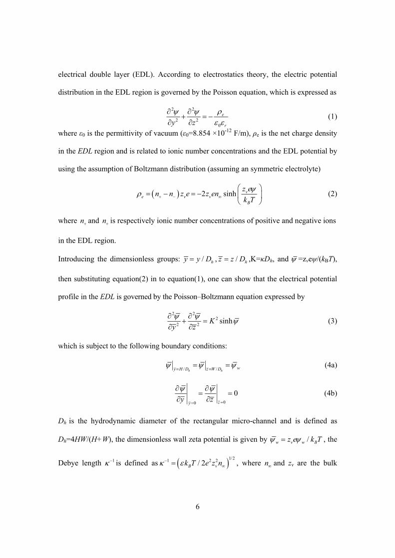
electrical double layer (EDL). According to electrostatics theory, the electric potential
distribution in the EDL region is governed by the Poisson equation, which is expressed as
2 2
2 20
e
ry z
(1)
where ε0 is the permittivity of vacuum (ε0=8.854 ×10⁻¹² F/m), ρe is the net charge density
in the EDL region and is related to ionic number concentrations and the EDL potential by
using the assumption of Boltzmann distribution (assuming an symmetric electrolyte)
2 sinh ve v v
B
z en n z e z en
k T
(2)
where n and n is respectively ionic number concentrations of positive and negative ions
in the EDL region.
Introducing the dimensionless groups: / hy y D , / hz z D ,K=κDh, and =zveψ/(kBT),
then substituting equation(2) in to equation(1), one can show that the electrical potential
profile in the EDL is governed by the Poisson–Boltzmann equation expressed by
2 22
2 2sinhK
y z
(3)
which is subject to the following boundary conditions:
/ /h hwy H D z W D
(4a)
00
0zy
y z
(4b)
Dh is the hydrodynamic diameter of the rectangular micro-channel and is defined as
Dh=4HW/(H+W), the dimensionless wall zeta potential is given by /w v w Bz e k T , the
Debye length 1 is defined as 1/21 2 2/ 2B vk T e z n , where n and zv are the bulk

7
number concentration and the valence of ions, respectively, e is the fundamental charge,
kB is the Boltzmann constant, and T is the absolute temperature.
2. 2 Electro-osmotic flow of power-law fluids
When an external electric field is applied, the liquid flow of an incompressible power-law
fluid induced by electro-osmosis is governed by the general momentum equations and
continuity equation, i.e.(Deen, 1998)
Tp
t
VV V V V F (5a)
0 V (5b)
where is the density, p is the pressure, F is the body force vector, v is the velocity
gradient tensor and vT is the transpose of velocity gradient tensor. is the
dynamic viscosity and its pertinent implications will be presented later.
The difference between non-Newtonian and Newtonian fluids lies in that the viscous
stress is not a linear function of the rate of strain tensor. A number of empirical
expressions have been used to describe variations in the apparent viscosity with the rate
of strain. A scalar measure of the rate of strain suitable for such expression, is the
magnitude of the rate of strain tensor, which is defined as the double dot product of the
rate of strain tensor (Deen, 1998)
1/ 2
1
2
Γ :Γ (6)
where Γ is the rate of strain tensor and is given by / 2T Γ = V V . The fluid
viscosity then can be expressed as a function of the magnitude , namely . In the
8
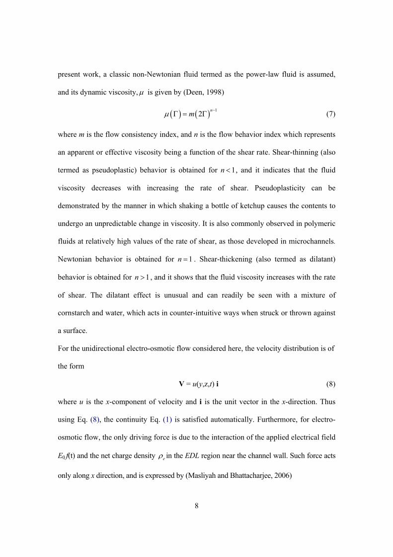
present work, a classic non-Newtonian fluid termed as the power-law fluid is assumed,
and its dynamic viscosity, is given by (Deen, 1998)
12
nm (7)
where m is the flow consistency index, and n is the flow behavior index which represents
an apparent or effective viscosity being a function of the shear rate. Shear-thinning (also
termed as pseudoplastic) behavior is obtained for 1n , and it indicates that the fluid
viscosity decreases with increasing the rate of shear. Pseudoplasticity can be
demonstrated by the manner in which shaking a bottle of ketchup causes the contents to
undergo an unpredictable change in viscosity. It is also commonly observed in polymeric
fluids at relatively high values of the rate of shear, as those developed in microchannels.
Newtonian behavior is obtained for 1n . Shear-thickening (also termed as dilatant)
behavior is obtained for 1n , and it shows that the fluid viscosity increases with the rate
of shear. The dilatant effect is unusual and can readily be seen with a mixture of
cornstarch and water, which acts in counter-intuitive ways when struck or thrown against
a surface.
For the unidirectional electro-osmotic flow considered here, the velocity distribution is of
the form
V = u(y,z,t) i (8)
where u is the x-component of velocity and i is the unit vector in the x-direction. Thus
using Eq. (8), the continuity Eq. (1) is satisfied automatically. Furthermore, for electro-
osmotic flow, the only driving force is due to the interaction of the applied electrical field
E0 f(t) and the net charge density e in the EDL region near the channel wall. Such force acts
only along x direction, and is expressed by (Masliyah and Bhattacharjee, 2006)

9
0x eF E f t (9)
For an open-end horizontally placed channel, no pressure gradient is induced and hence
the pressure gradient term in the Cauchy momentum equation disappears.
Besides the nondimensional groups used in the previous subsection, introducing
additional nondimensional parameters
1 1n ns h
mtt
u D ,s
uu
u (10)
and taking into account the aforementioned considerations, the simplified
nondimensional counterpart for equation (4) reads
1
sinhn
nw
u u u Kf t
t y y z z n
(11)
In which can be expressed as
1
2 2 21
2
n
n u u
y z
(12)
In Eq.(10), us represents the generalized Smoluchowski velocity for power-law liquids
(María et al., 2009; Zhao et al., 2008), and given by
11
0n n
wns
Eu n
m
(13)
The initial and boundary conditions applicable to equation (11) are
00
tu
(14a)
0
0y
u
y
,
0
0z
u
z
(14b)

10
/0
hy W Du
,
/0
z H Wu
(14c)
3 Numerical methods and model validation
In the present analysis, both EDL potential field and electro-osmotic flow field are solved
in the PDE mode embedded in the popular finite element numerical analysis package
COMSOL multiphysics 3.4. In the PDE mode, the general form of PDEs are given in
terms of a lot of coefficients and a source term which are left for the user to specify for
constructions of their models. These coefficients can either be constant or dependent on
spatiotemporal variables and the source term can either be a linear or nonlinear function
of sought quantities, generating great flexibility for handling nonlinear PDEs. In our work,
a PDE governs the EDL potential and a PDE governs electro-osmotic flow field are
constructed from the general form of PDEs. Through the source term sinh in equations
(11), these two PDEs are coupled together.
In order to check the validity of the present model, we compare our numerical results
with the exact results (Chang and Wang, 2008) derived for the velocity distribution for
the starting electro-osmotic flow of Newtonian fluids in a rectangular microchannel.
However, their result only can be used in limited situations due to the linear Debye-
Hückel approximation involved in the analysis, which usually requires the wall zeta
potential to be smaller than -25mV. Thus, in our numerical validation, the channel has a
uniform wall zeta potential of ψw=-25mV and geometric size of the microchannel is
given as 2H=10μm and 2W=15μm. The working fluid flowing in the microchannel is
formed by dissolving a symmetric electrolyte (z:z), say NaCl, in a Newtonian fluid (a
special power-law fluid with flow behavior index n=1), and the bulk ionic number
concentration is n∞=6.022×10²⁰/m3 (c∞=10-6M). The dielectric constant εr of the

11
electrolytic solution is taken to be the same as the room temperature water, namely εr
=78.5. In electro-osmotic flows, the velocity experiences drastic changes in the EDL
region near the channel wall. Therefore, in the present analysis, we densify the grids near
the channel wall to ensure that the velocity characteristics in the EDL can be captured.
The calculated solutions are carefully validated to ensure that they are independent of the
computational grid points and time step. Grid-independence was examined for two
different grids whose total cell numbers were 6700 (100 67) and 1500 (100 150)
respectively. We also examined two different time steps, i.e. 1 310 and 5 410 , to
exclude the time-step dependency. It was found that the calculated flow rates differences
under two examinations were both less than 1%. Therefore, the grid and time
independence were corroborated, and the grid with 6700 cells and time step of 1 310
were applied in the study.
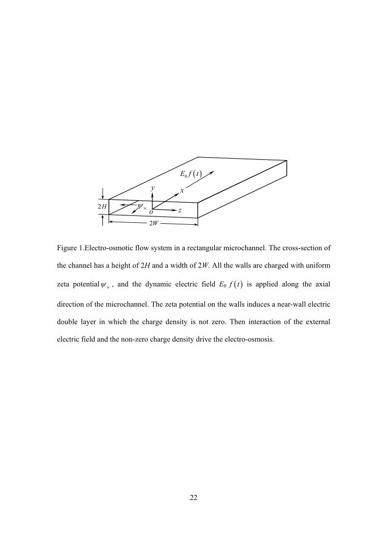
Figure 2 shows the velocity profiles for three different times at 0y , respectively
computed by using the analytical formula (Chang and Wang, 2008) and our devised
COMSOL model. It can be perceived from this plot that the numerical results for velocity
distributions obtained from our COMSOL model at three different times agree very well
with the existing analytical model, which indicates that our COMSOL model is of high
accuracy to predict transient electro-osmotic flow of power-law fluids in rectangular
microchannels.
4 Results and discussion
To predict the dynamic behaviors of the transient electro-osmotic flow of power-law
fluids under both DC and AC electric fields, we take all the parameters the same as in the

12
Section 3 except that a relatively large wall zeta potential of ψw=-100mV is prescribed for
all the microchannel walls. The resultant dimensionless electrokinetic parameter K=40,
which secures the microchannel has relatively thin EDL and thus the dynamic momentum
transfer between the EDL and bulk flow can be identified.
4.1 Transient electro-osmotic flows of power-law fluids under DC electric fields
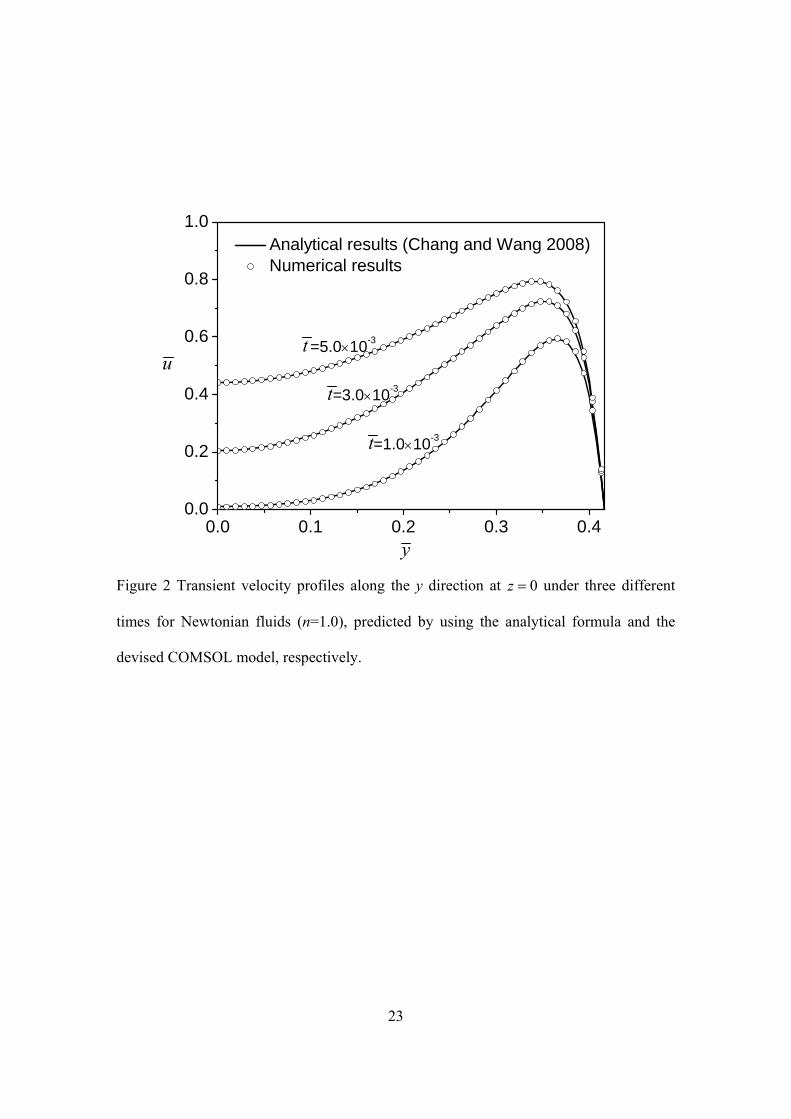
Figures 3 shows typical instant electro-osmotic flow velocity profiles of power-law fluids
with n=0.8. When the electric field is initially applied, the fluid within the double layer
responds virtually immediately, but the bulk fluid in the microchannel remains stationary.
The evolution of the velocity distributions throughout the microchannel cross-section
reveals a unique characteristic of the electro-osmotic flow. It is observed that the liquid
flow starts within a thin layer adjacent to the channel wall, i.e., the EDL region. During
elapsed dimensionless time of the order of 10-3, the velocity develops rapidly from zero
and reaches a local maximum velocity inside the EDL region, and then drops gradually to
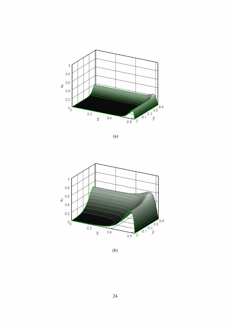
zero as the distance is away from the channel wall. Because the electro-osmotic flow is
driven by the electrical forces resulting from the action of an external electrical field and
the EDL field, such driving forces exist only inside the EDL region where the electrical
net charge is present. The flow in this region may be viewed as “active.” However, as the
fluid velocity within the double layer continue to increase; the bulk fluid is gradually
dragged into motion through the transfer of momentum from the double layer, finally this
impact extends to the channel center. Hence the flow outside the EDL region may be
considered as “passive” flow caused by viscous forces. At the steady-state situation, the
velocity exhibits a plug flow. Notice also the absolute maximum is near the corner, which
is peculiar to channels with corners. This corner effect was also previously observed (Luo,

13
2004) in a numerical study carried out for Newtonian liquid. This phenomenon is
demonstrated during the early stage of the evolution of the electroosmosis. The presence
of such “corner effect” is due to the overlap of the two EDLs formed at the two adjacent
sides of the rectangular channel wall.
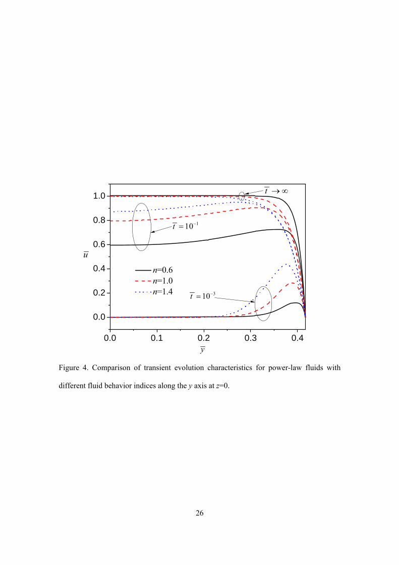
Fig.4 characterizes the transient evolution characteristics for electroosmosis for power-
law fluids with different fluid behavior indices along the y axis at z=0. At the same
instant time 10-3, the fluids with larger fluid behavior indices respond more promptly to
the external electric field inside the EDL. As time elapse, momentum transfer from the
EDL to the bulk fluid progress and the fluids with larger fluid behavior more quickly
approach the steady state. At steady state, the normalized velocity in the bulk fluid all
increase to unit one, which reveals that for fluids with different fluid behavior indices, the
electro-osmotic velocities in the bulk liquid all approach their corresponding generalized
Smoluchowski velocities at the steady sate. Furthermore, the present numerical
simulations demonstrate that the generalized Smoluchowski velocity derived in the
parallel plate slit channels (María et al., 2009; Zhao et al., 2008) is also valid for the
electro-osmotic flow of power-law fluids in microchannel with rectangular cross-sections.
For situations where we have large-sized channels or thin EDLs (i.e., 1K ), the steady-
state electro-osmotically driven power-law fluid in the microchannels moves like a plug
with velocity given by generalized Smoluchowski velocity equation (13). Thus, this
generalized Smoluchowski velocity can play the role of the conventional Smoluchowski
velocity (n=1 in equation (1)) in microfluidic applications dealing with non-Newtonian
fluids.
4.2 Electro-osmotic flows of power-law fluids under AC electric fields
14
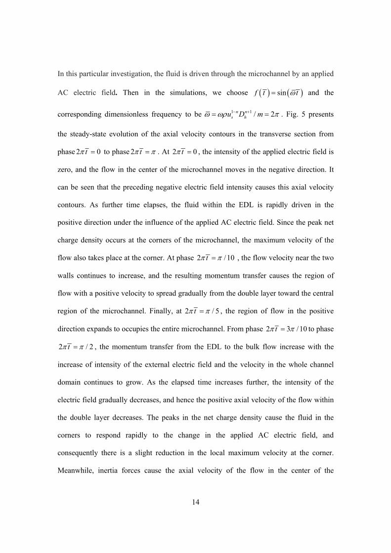
In this particular investigation, the fluid is driven through the microchannel by an applied
AC electric field. Then in the simulations, we choose sinf t t and the
corresponding dimensionless frequency to be 1 1 / 2n ns hu D m . Fig. 5 presents
the steady-state evolution of the axial velocity contours in the transverse section from
phase 2 0t to phase 2 t . At 2 0t , the intensity of the applied electric field is
zero, and the flow in the center of the microchannel moves in the negative direction. It
can be seen that the preceding negative electric field intensity causes this axial velocity
contours. As further time elapses, the fluid within the EDL is rapidly driven in the
positive direction under the influence of the applied AC electric field. Since the peak net
charge density occurs at the corners of the microchannel, the maximum velocity of the
flow also takes place at the corner. At phase 2 /10t , the flow velocity near the two
walls continues to increase, and the resulting momentum transfer causes the region of
flow with a positive velocity to spread gradually from the double layer toward the central
region of the microchannel. Finally, at 2 / 5t , the region of flow in the positive
direction expands to occupies the entire microchannel. From phase 2 3 /10t to phase
2 / 2t , the momentum transfer from the EDL to the bulk flow increase with the
increase of intensity of the external electric field and the velocity in the whole channel
domain continues to grow. As the elapsed time increases further, the intensity of the
electric field gradually decreases, and hence the positive axial velocity of the flow within
the double layer decreases. The peaks in the net charge density cause the fluid in the
corners to respond rapidly to the change in the applied AC electric field, and
consequently there is a slight reduction in the local maximum velocity at the corner.
Meanwhile, inertia forces cause the axial velocity of the flow in the center of the

15
microchannel to continue to increase in the positive direction. At phase 2 3 / 5t , the
velocity of the bulk flow in the positive direction reaches an almost equal value. After
phase 2 7 /10t , the positive intensity of the applied AC electric field continues to
decrease, and momentum transfer causes the region of flow with slower positive axial
velocity to expand toward the central region. At phase 2 t , it is noted that the axial-
flow velocity contours strongly resemble those evident at phase 2 0t in terms of
their shape. However, it is important to note that the direction of the axial velocity is
reversed. During the second half of the cycle, from 2 t to 2 2t , the variation
of the applied AC electric field intensity is the mirror image of the variation described
from 2 0t to 2 t , and accordingly, the axial flow velocity in the central region
of the microchannel reverses from a positive direction to a negative direction. Essentially,
the evolution of the axial velocity contours during the cycle from 2 t to 2 2t
follows the same process as that described for 2 0t to 2 t . However, it is noted
that the axial flow directions are reversed. Consequently, at 2 2t , the axial velocity
contours are identical to those observed at 2 0t .
Fig.6 displays the transient evolutions in applied AC electric field and axial velocity of
electro-osmotic flow of power-law fluids with three different flow behavior indices in
transverse center ( 0y z ) of the microchannel. After turning on the AC electric fields,
the fluids with larger fluid behavior index responds more quickly as in the DC electric
field. Generally, the velocity lags behind the applied AC electric field, and the phase lag
increases with the increase of the fluid behavior index, but not astonishingly. We also
note that from one peak to the adjacent trough, the power-law fluids experience more
significant accelerations for the larger fluid behavior indices. In addition, the amplitudes

16
of oscillating velocities are closer to the corresponding generalized Smoluchowski
velocity with the increase of fluid behavior index.
5 Conclusions
We conducted numerical analyses of dynamic electrokinetic flow of power-law fluids in
a rectangular microchannel by using finite element method. For the case of transient
electroosmotic flow with an external DC electric field, initially, the impulse provided by
the applied DC electric field drives the fluid within the double layer in the axial direction.
The momentums of the double layer gradually transfer to the central region, and finally
occupying the entire channel. The greater fluid behavior index causes the fluid to respond
more promptly to the influence of the applied electric field. In addition, our numerical
calculation confirms that the Smoluchowski velocity given in the previous works for a
parallel plate microchannel is still valid for microchannels with rectangular cross-sections.
The velocity is of practical importance in non-Newtonian microfluidic manipulations
adopting electroosmosis.
This study also considered the application of a sinusoidal electric field to the flow in the
microchannel. The results indicate that the flow in the center of the microchannel initially
exhibits a transient response when the electric field is applied and then attains a steady-
state oscillation. The fluid with larger fluid behavior index respond tends to have a faster
response to the electric field and a larger phase lag between the applied electric field.
Furthermore, the fluids with larger fluid behavior indices are more susceptible to
acceleration initiated by the oscillating electric field. The greater net charge density in the
corners of the microchannel results in local maximum or minimum axial velocities in the
17
corners during increasing or decreasing applied electric field intensity in either the
positive or negative direction. It has been shown that the axial-flow velocity tends to
follow the varying intensity of the applied AC electric field. The evolution process of the
axial velocity contours during a half cycle is actually a mirror image for the preceding
half cycle.
Acknowledgments Z.C.L. would like to thank NTU (Nanyang technological university,
Republic of Singapore) for a PhD scholarship.
References Afonso AM, Alves MA, Pinho FT (2009) Analytical solution of mixed electro-osmotic/pressure driven
flows of viscoelastic fluids in microchannels. Journal of Non-Newtonian Fluid Mechanics 159:
50-63
Ajdari A (2000) Pumping liquids using asymmetric electrode arrays. Physical Review E - Statistical
Physics, Plasmas, Fluids, and Related Interdisciplinary Topics 61
Berli C (2009) Output pressure and efficiency of electrokinetic pumping of non-Newtonian fluids.
Microfluidics and Nanofluidics
Bousse L, Cohen C, Nikiforov T, Chow A, Kopf-Sill AR, Dubrow R, Parce JW (2000) Electrokinetically
controlled microfluidic analysis systems. Annual Review of Biophysics and Biomolecular
Structure 29: 155-181
Campisi M, Accoto D, Dario P (2005) ac electroosmosis in rectangular microchannels. The Journal of
Chemical Physics 123: 204724-204729
Chang CC, Wang CY (2008) Starting electroosmotic flow in an annulus and in a rectangular channel.
ELECTROPHORESIS 29: 2970-2979
Das M, Jain VK, Ghoshdastidar PS (2008) Fluid flow analysis of magnetorheological abrasive flow
finishing (MRAFF) process. International Journal of Machine Tools and Manufacture 48: 415-426
Das S, Chakraborty S (2006) Analytical solutions for velocity, temperature and concentration distribution
in electroosmotic microchannel flows of a non-Newtonian bio-fluid. Analytica Chimica Acta 559:
15-24
Deen WM (1998) Analysis of Transport Phenomena. Oxford University Press, New York

18
Dose EV, Guiochon G (1993) Timescales of transient processes in capillary electrophoresis. Journal of
Chromatography 652: 263-275
Fan ZH, Harrison DJ (1994) Micromachining of capillary electrophoresis injectors and separators on glass
chips and evaluation of flow at capillary intersections. Analytical Chemistry 66: 177-184
González A, Ramos A, Green NG, Castellanos A, Morgan H (2000) Fluid flow induced by nonuniform ac
electric fields in electrolytes on microelectrodes. II. A linear double-layer analysis. Physical
Review E - Statistical Physics, Plasmas, Fluids, and Related Interdisciplinary Topics 61: 4019-
4028
Graham DI, Jones TER (1994) Settling and transport of spherical particles in power-law fluids at finite
Reynolds number. Journal of Non-Newtonian Fluid Mechanics 54: 465-488
Hanna WT, Osterle JF (1968) Transient electro-osmosis in capillary tubes. The Journal of Chemical
Physics 49: 4062-4068
Harrison DJ, Fluri K, Seiler K, Fan Z, Effenhauser CS, Manz A (1993) Micromachining a miniaturized
capillary electrophoresis-based chemical analysis system on a chip. Science 261: 895-897
Ivory CF (1983) Transient electroosmosis: The momentum transfer coefficient. Journal of Colloid and
Interface Science 96: 296-298
Jacobson SC, Culbertson CT, Daler JE, Ramsey JM (1998) Microchip structures for submillisecond
electrophoresis. Analytical Chemistry 70: 3476-3480
Jacobson SC, Hergenr 枚 der R, Koutny LB, Michael Ramsey J (1994) High-Speed Separations on a
Microchip. Analytical Chemistry 66: 1114-1118
Kang Y, Yang C, Huang X (2002) Dynamic aspects of electroosmotic flow in a cylindrical microcapillary.
International Journal of Engineering Science 40: 2203-2221
Keh HJ, Tseng HC (2001) Transient electrokinetic flow in fine capillaries. Journal of Colloid and Interface
Science 242: 450-459
Khellaf K, Lauriat G (2000) Numerical study of heat transfer in a non-Newtonian Carreau-fluid between
rotating concentric vertical cylinders. Journal of Non-Newtonian Fluid Mechanics 89: 45-61
Koh YH, Ong NS, Chen XY, Lam YC, Chai JC (2004) EFFECT OF TEMPERATURE AND INLET
VELOCITY ON THE FLOW OF A NONNEWTONIAN FLUID. International Communications
in Heat and Mass Transfer 31: 1005-1013
Luo WJ (2004) Transient electroosmotic flow induced by DC or AC electric fields in a curved microtube.
Journal of Colloid and Interface Science 278: 497-507
Manz A, Effenhauser CS, Burggraf N, Harrison DJ, Seiler K, Fluri K (1994) Electroosmotic pumping and
electrophoretic separations for miniaturized chemical analysis systems. Journal of
Micromechanics and Microengineering 4: 257-265
María LO, Luciana V-C, Claudio LAB (2009) The EOF of polymer solutions. ELECTROPHORESIS 30:
921-928

19
Masliyah JH, Bhattacharjee S (2006) Electrokinetic and Colloid Transport Phenomena. Wiley-Interscience,
Hoboken, N.J.
Mishchuk NA, González-Caballero F (2006) Nonstationary electroosmotic flow in open cylindrical
capillaries. ELECTROPHORESIS 27: 650-660
Park HM, Lee WM (2008) Effect of viscoelasticity on the flow pattern and the volumetric flow rate in
electroosmotic flows through a microchannel. Lab on a Chip - Miniaturisation for Chemistry and
Biology 8: 1163-1170
Ramos A, Morgan H, Green NG, Castellanos A (1999) AC electric-field-induced fluid flow in
microelectrodes. Journal of Colloid and Interface Science 217: 420-422
Söderman O, Jönsson B (1996) Electro-osmosis: Velocity profiles in different geometries with both
temporal and spatial resolution. Journal of Chemical Physics 105: 10300-10311
Squires TM, Quake SR (2005) Microfluidics: Fluid physics at the nanoliter scale. Reviews of Modern
Physics 77: 977-1026
Tang GH, Li XF, He YL, Tao WQ (2009) Electroosmotic flow of non-Newtonian fluid in microchannels.
Journal of Non-Newtonian Fluid Mechanics 157: 133-137
Whitesides GM (2006) The origins and the future of microfluidics. Nature 442: 368-373
Yan D, Yang C, Huang XY (2007b) Effect of finite reservoir size on electroosmotic flow in microchannels.
Microfluidics and Nanofluidics 3: 333-340
Yan D, Yang C, Nguyen NT, Huang X (2007a) Diagnosis of transient electrokinetic flow in microfluidic
channels. Physics of Fluids 19
Yang C, Ng CB, Chan V (2002) Transient analysis of electroosmotic flow in a slit microchannel. Journal of
Colloid and Interface Science 248: 524-527
Yang J, Kwok DY (2003) Time-dependent laminar electrokinetic slip flow in infinitely extended
rectangular microchannels. The Journal of Chemical Physics 118: 354-363
Yossifon G, Frankel I, Miloh T (2009) Macro-scale description of transient electro-kinetic phenomena over
polarizable dielectric solids. Journal of Fluid Mechanics 620: 241-262
Zhang Y, Wong TN, Yang C, Ooi KT (2006) Dynamic aspects of electroosmotic flow. Microfluidics and
Nanofluidics 2: 205-214
Zhao C, Yang C (2009) Exact solutions for electro-osmotic flow of viscoelastic fluids in rectangular micro-
channels. Applied Mathematics and Computation 211: 502-509
Zhao C, Yang C (2010) Nonlinear Smoluchowski velocity for electroosmosis of Power-law fluids over a
surface with arbitrary zeta potentials. ELECTROPHORESIS 31: 973-979
Zhao C, Zholkovskij E, Masliyah JH, Yang C (2008) Analysis of electroosmotic flow of power-law fluids
in a slit microchannel. Journal of Colloid and Interface Science 326: 503-510
Zimmerman W, Rees J, Craven T (2006) Rheometry of non-Newtonian electrokinetic flow in a
microchannel T-junction. Microfluidics and Nanofluidics 2: 481-492
20
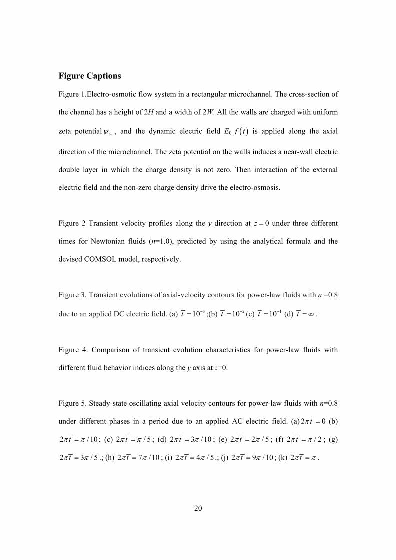
Figure Captions Figure 1.Electro-osmotic flow system in a rectangular microchannel. The cross-section of
the channel has a height of 2H and a width of 2W. All the walls are charged with uniform
zeta potential w , and the dynamic electric field E0 f t is applied along the axial
direction of the microchannel. The zeta potential on the walls induces a near-wall electric
double layer in which the charge density is not zero. Then interaction of the external
electric field and the non-zero charge density drive the electro-osmosis.
Figure 2 Transient velocity profiles along the y direction at 0z under three different
times for Newtonian fluids (n=1.0), predicted by using the analytical formula and the
devised COMSOL model, respectively.
Figure 3. Transient evolutions of axial-velocity contours for power-law fluids with n =0.8
due to an applied DC electric field. (a) 310t ;(b) 210t (c) 110t (d) t .
Figure 4. Comparison of transient evolution characteristics for power-law fluids with
different fluid behavior indices along the y axis at z=0.
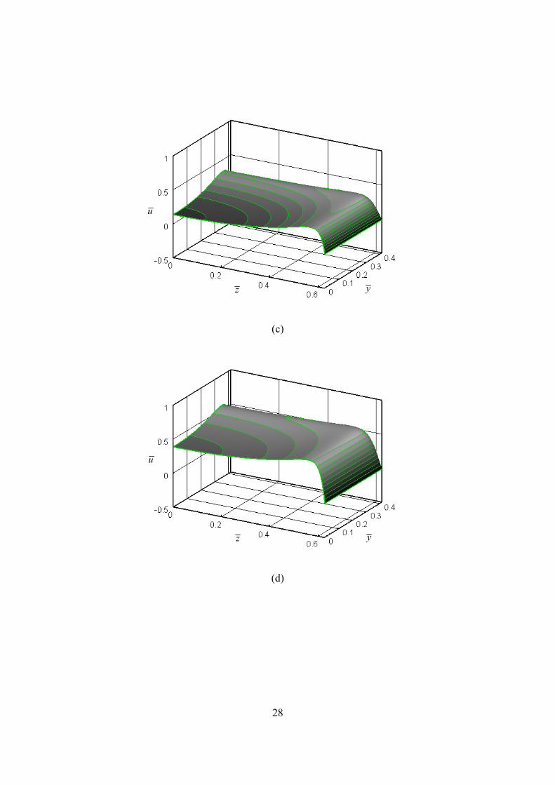
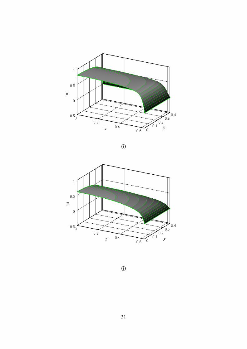
Figure 5. Steady-state oscillating axial velocity contours for power-law fluids with n=0.8
under different phases in a period due to an applied AC electric field. (a) 2 0t (b)
2 /10t ; (c) 2 / 5t ; (d) 2 3 /10t ; (e) 2 2 / 5t ; (f) 2 / 2t ; (g)
2 3 / 5t .; (h) 2 7 /10t ; (i) 2 4 / 5t .; (j) 2 9 /10t ; (k) 2 t .

21
Figure 6. Transient evolutions in applied AC electric field and axial velocity of electro-
osmotic flow of power-law fluids with three different flow behavior indices in transverse
center ( 0y z ) of the microchannel. The dash-dot line represents the scaled electric
field (( sin 2 t ), the dash line represents the scaled velocity for Newtonian fluids (n=1),
Thick solid line is the scaled velocity for the power-law fluids with n=0.6, and thin solid
line denotes the scaled velocity for the power law fluids with n=1.4.
22
Figure 1.Electro-osmotic flow system in a rectangular microchannel. The cross-section of
the channel has a height of 2H and a width of 2W. All the walls are charged with uniform
zeta potential w , and the dynamic electric field E0 f t is applied along the axial
direction of the microchannel. The zeta potential on the walls induces a near-wall electric
double layer in which the charge density is not zero. Then interaction of the external
electric field and the non-zero charge density drive the electro-osmosis.
2W
2H z
y x
o
0E f t
w
23
0.0 0.1 0.2 0.3 0.40.0
0.2
0.4
0.6
0.8
1.0
u
t
y
Analytical results (Chang and Wang 2008) Numerical results
=1.010-3
t=3.010-3
t =5.010-3
Figure 2 Transient velocity profiles along the y direction at 0z under three different
times for Newtonian fluids (n=1.0), predicted by using the analytical formula and the
devised COMSOL model, respectively.
24
(a)
(b)
yz
u
yz
u

25
(c)
(d)
Figure 3. Transient evolutions of axial-velocity contours for power-law fluids with n =0.8
due to an applied DC electric field. (a) 310t ;(b) 210t (c) 110t (d) t .
yz
u
yz
u
26
0.0 0.1 0.2 0.3 0.4
0.0
0.2
0.4
0.6
0.8
1.0
110t
310t
t
u
y
n=0.6 n=1.0 n=1.4
Figure 4. Comparison of transient evolution characteristics for power-law fluids with
different fluid behavior indices along the y axis at z=0.

27
(a)
(b)
u
z y
u
z y
28
(c)
(d)
u
z y
u
z y

29
(e)
(f)
u
z y
u
z y

30
(g)
(h)
u
z y
u
z y
31
(i)
(j)
u
z y
u
z y

32
(k)
Figure 5. Steady-state oscillating axial velocity contours for power-law fluids with n=0.8
under different phases in a period due to an applied AC electric field. (a) 2 0t (b)
2 /10t ; (c) 2 / 5t ; (d) 2 3 /10t ; (e) 2 2 / 5t ; (f) 2 / 2t ; (g)
2 3 / 5t .; (h) 2 7 /10t ; (i) 2 4 / 5t .; (j) 2 9 /10t ; (k) 2 t .
u
z y

33
0 1 2 3 4 5
-1.0
-0.8
-0.6
-0.4
-0.2
0.0
0.2
0.4
0.6
0.8
1.0
t
u
Figure 6. Transient evolutions in applied AC electric field and axial velocity of electro-
osmotic flow of power-law fluids with three different flow behavior indices in transverse
center ( 0y z ) of the microchannel. The dash-dot line represents the scaled electric
field (( sin 2 t ), the dash line represents the scaled velocity for Newtonian fluids (n=1),
Thick solid line is the scaled velocity for the power-law fluids with n=0.6, and thin solid
line denotes the scaled velocity for the power law fluids with n=1.4.