
Numerical analysis of different methods to calculate residual stresses in thin films based on...
10
http://journals.cambridge.org Downloaded: 28 Aug 2014 IP address: 137.207.120.173 Numerical analysis of different methods to calculate residual stresses in thin films based on instrumented indentation data Carlos Eduardo Keutenedjian Mady a) Department of Mechanical Engineering, Polytechnic School of the University of São Paulo, 05508-900, São Paulo, Brazil Sara Aida Rodriguez Department of Mechanical Engineering, Polytechnic School of the University of São Paulo, 05508-900, São Paulo, Brazil; and Research Group of Fatigue and Surface, Mechanical Engineering School, Universidad del, Valle, Cll 13 No 100-00 Cali, Colombia Adriana Gómez Gómez Department of Mechanical Engineering, Polytechnic School of the University of São Paulo, 05508-900, São Paulo, Brazil; and Faculty of Engineering of Pontificia Universidad Javeriana Cali, Cll 18 No. 118-250 Cali, Colombia Roberto Martins Souza Department of Mechanical Engineering, Polytechnic School of the University of São Paulo, 05508-900, São Paulo, Brazil (Received 7 October 2011; accepted 8 May 2012) In this work, different methods to estimate the value of thin film residual stresses using instrumented indentation data were analyzed. This study considered procedures proposed in the literature, as well as a modification on one of these methods and a new approach based on the effect of residual stress on the value of hardness calculated via the Oliver and Pharr method. The analysis of these methods was centered on an axisymmetric two-dimensional finite element model, which was developed to simulate instrumented indentation testing of thin ceramic films deposited onto hard steel substrates. Simulations were conducted varying the level of film residual stress, film strain hardening exponent, film yield strength, and film Poisson’s ratio. Different ratios of maximum penetration depth h max over film thickness t were also considered, including h/t 5 0.04, for which the contribution of the substrate in the mechanical response of the system is not significant. Residual stresses were then calculated following the procedures mentioned above and compared with the values used as input in the numerical simulations. In general, results indicate the difference that each method provides with respect to the input values depends on the conditions studied. The method by Suresh and Giannakopoulos consistently overestimated the values when stresses were compressive. The method provided by Wang et al. has shown less dependence on h/t than the others. I. INTRODUCTION The correlation between residual stresses and data from instrumented indentation testing (IIT) has been the subject of a significant number of publication in the past 15 years. In general, these publications may be divided into analysis on how residual stresses affect the load– displacement curve (also called the direct method) and analysis on how to calculate the value of residual stress based on instrumented indentation data (inverse method). A. Effects of residual stress on IIT Contributions toward the analysis of the effects of residual stresses on instrumented indentation data may be found in the works by Tsui et al. 1 and Bolshakov et al. 2 In the first case, 1 results initially confirmed a trend published in the literature, 3 according to which tensile residual stresses decrease the value of hardness measured during, e.g., Rockwell B tests, while compressive residual stresses are responsible for an increase in hardness values. In this case, the effects are more evident when the stresses are tensile. Tsui et al. 1 also indicated that, in addition to hard- ness, the calculated values of elastic modulus are affected by residual stresses, when using IIT data, but the effects do not exceed 10%. A more careful analysis conducted by the authors, 1 which included the use of the real contact area (measured optically), indicated that there is no actual influence of residual stresses on the mechanical properties of an aluminum alloy. At the same time, Bolshakov et al. 2 conducted a finite element analysis to study the same aluminum alloy as Tsui et al., 1 to validate their results. The study revealed that residual stresses affect the amount of indentation pile-up, whose formation is favored in the presence of compressive residual stresses, affecting the results of contact area cal- culated with the Oliver and Pharr method 4,5 and affecting a) Address all correspondence to this author. e-mail: [email protected], [email protected] DOI: 10.1557/jmr.2012.166 J. Mater. Res., Vol. 27, No. 13, Jul 14, 2012 Ó Materials Research Society 2012 1732
-
Upload
roberto-martins -
Category
Documents
-
view
212 -
download
0
Transcript of Numerical analysis of different methods to calculate residual stresses in thin films based on...

http://journals.cambridge.org Downloaded: 28 Aug 2014 IP address: 137.207.120.173
Numerical analysis of different methods to calculate residual stressesin thin films based on instrumented indentation data
Carlos Eduardo Keutenedjian Madya)
Department of Mechanical Engineering, Polytechnic School of the University of São Paulo, 05508-900, São Paulo, Brazil
Sara Aida RodriguezDepartment of Mechanical Engineering, Polytechnic School of the University of São Paulo, 05508-900, São Paulo,Brazil; and Research Group of Fatigue and Surface, Mechanical Engineering School, Universidad del, Valle, Cll 13No 100-00 Cali, Colombia
Adriana Gómez GómezDepartment of Mechanical Engineering, Polytechnic School of the University of São Paulo, 05508-900, São Paulo,Brazil; and Faculty of Engineering of Pontificia Universidad Javeriana Cali, Cll 18 No. 118-250 Cali, Colombia
Roberto Martins SouzaDepartment of Mechanical Engineering, Polytechnic School of the University of São Paulo, 05508-900, São Paulo, Brazil
(Received 7 October 2011; accepted 8 May 2012)
In this work, different methods to estimate the value of thin film residual stresses usinginstrumented indentation data were analyzed. This study considered procedures proposed in theliterature, as well as a modification on one of these methods and a new approach based on the effectof residual stress on the value of hardness calculated via the Oliver and Pharr method. The analysisof these methods was centered on an axisymmetric two-dimensional finite element model, whichwas developed to simulate instrumented indentation testing of thin ceramic films deposited ontohard steel substrates. Simulations were conducted varying the level of film residual stress, film strainhardening exponent, film yield strength, and film Poisson’s ratio. Different ratios of maximumpenetration depth hmax over film thickness t were also considered, including h/t5 0.04, for which thecontribution of the substrate in the mechanical response of the system is not significant. Residualstresses were then calculated following the procedures mentioned above and compared with thevalues used as input in the numerical simulations. In general, results indicate the difference that eachmethod provides with respect to the input values depends on the conditions studied. The method bySuresh and Giannakopoulos consistently overestimated the values when stresses were compressive.The method provided by Wang et al. has shown less dependence on h/t than the others.
I. INTRODUCTION
The correlation between residual stresses and datafrom instrumented indentation testing (IIT) has been thesubject of a significant number of publication in the past15 years. In general, these publications may be dividedinto analysis on how residual stresses affect the load–displacement curve (also called the direct method) andanalysis on how to calculate the value of residual stressbased on instrumented indentation data (inverse method).
A. Effects of residual stress on IIT
Contributions toward the analysis of the effects ofresidual stresses on instrumented indentation data may befound in the works by Tsui et al.1 and Bolshakov et al.2 Inthe first case,1 results initially confirmed a trend published
in the literature,3 according to which tensile residualstresses decrease the value of hardness measured during,e.g., Rockwell B tests, while compressive residual stressesare responsible for an increase in hardness values. In thiscase, the effects are more evident when the stresses aretensile. Tsui et al.1 also indicated that, in addition to hard-ness, the calculated values of elastic modulus are affectedby residual stresses, when using IIT data, but the effects donot exceed 10%. Amore careful analysis conducted by theauthors,1 which included the use of the real contact area(measured optically), indicated that there is no actualinfluence of residual stresses on the mechanical propertiesof an aluminum alloy.
At the same time, Bolshakov et al.2 conducted a finiteelement analysis to study the same aluminum alloy as Tsuiet al.,1 to validate their results. The study revealed thatresidual stresses affect the amount of indentation pile-up,whose formation is favored in the presence of compressiveresidual stresses, affecting the results of contact area cal-culated with the Oliver and Pharr method4,5 and affecting
a)Address all correspondence to this author.e-mail: [email protected], [email protected]
DOI: 10.1557/jmr.2012.166
J. Mater. Res., Vol. 27, No. 13, Jul 14, 2012 �Materials Research Society 20121732
http://journals.cambridge.org Downloaded: 28 Aug 2014 IP address: 137.207.120.173
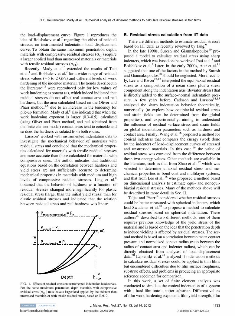
the load–displacement curve. Figure 1 reproduces theidea of Bolshakov et al.2 regarding the effect of residualstresses on instrumented indentation load–displacementcurve. To obtain the same maximum penetration depth,materials with compressive residual stresses (rr;c) requirea larger applied load than unstressed materials or materialswith tensile residual stresses (rr;t).
Recently, Mady et al.6 extended the results of Tsuiet al.1 and Bolshakov et al.2 for a wider range of residualstress values (�5 to 2 GPa) and different levels of workhardening of the indented material. The trends described inthe literature1,2 were reproduced only for low values ofwork hardening exponent (n), which indeed indicated thatresidual stresses do not affect real contact area and realhardness, but the area calculated based on the Oliver andPharr method,4,5 due to an increase in the tendency forpile-up formation. Mady et al.6 also indicated that when thework hardening exponent is larger (0.3–0.5), calculated(using Oliver and Pharr method) and real (obtained fromthe finite element model) contact areas tend to coincide andso does the hardness calculated from both routes.
Larsson7 worked with instrumented indentation data toinvestigate the mechanical behavior of materials withresidual stress and concluded that the mechanical proper-ties calculated for materials with tensile residual stressesare more accurate than those calculated for materials withcompressive ones. The author indicates that traditionalequations based on the correlation between hardness andyield stress are not sufficiently accurate to determinemechanical properties in materials with medium and highlevels of compressive residual stresses. Ling et al.8
obtained that the behavior of hardness as a function ofresidual stresses changed more significantly for plasticresidual stress (larger than the initial yield stress) than forelastic residual stresses and indicated that the relationbetween residual stress and real hardness was linear.
B. Residual stress calculation from IIT data
There are different methods to estimate residual stressesbased on IIT data, as recently reviewed by Jang.9
In the late 1990s, Suresh and Giannakopoulos10 pro-posed a model to calculate residual stress using sharpindenters, which was based on the works of Tsui et al.1 andBolshakov et al.2 Later, in the early 2000s, Atar et al.11
suggested that one of the factors in the method by Sureshand Giannakopoulos10 should be neglected. More recent-ly, Lee and Kwon12,13 interpreted the equibiaxial residualstress as a composition of a mean stress plus a stresscomponent along the indentation axis (deviator stress) thatis directly added to the surface–normal indentation pres-sure. A few years before, Carlsson and Larsson14,15
analyzed the sharp indentation behavior theoretically,numerically (to explore how equibiaxial residual stressand strain fields can be determined from the globalproperties), and experimentally, aiming to understandthe influence of residual surface stress and strain fieldson global indentation parameters such as hardness andcontact area. Finally, Wang et al.16 proposed a method forconical indenters that compares the energy (work doneby the indenter) of load–displacement curves of stressedand unstressed materials. In this case,16 the value ofresidual stress was extracted from the difference betweenthese two energy values. Other methods are available inthe literature, such as that from Zhao et al.,17 which wasselected to determine uniaxial residual stress and me-chanical properties in bond coat and multilayer systems;and that from Lee et al.,18 who proposed a method basedon dimensional analysis to estimate equi- and nonequi-biaxial residual stresses. Many of the methods above willbe described in more detail in Sec. II.
Taljat and Pharr19 considered whether residual stressescould be better measured with spherical indenters, whichlead Swadener et al.20 to propose a method to calculateresidual stresses based on spherical indentation. Theseauthors20 described two different methods: one of themrequires previous knowledge of the yield stress of thematerial and is based on the idea that the penetration depthto induce yielding is affected by residual stresses. The sec-ond method is based on a correlation between mean contactpressure and normalized contact radius (ratio between theradius of contact area and indenter radius), which can bedirectly obtained from analyses of load–displacementdata.20 Lepienski et al.21 analyzed if indentation methodsto calculate residual stresses could be applied to thin filmsbut encountered difficulties due to film surface roughness,substrate effects, and problems in producing an appropriatereference specimen for comparison.
In this work, a set of finite element analysis wasconducted to simulate the conical indentation of a systemwith a hard film onto a softer substrate. Different valuesof film work hardening exponent, film yield strength, film
FIG. 1. Effects of residual stress on instrumented indentation load curves.For the same maximum penetration depth materials with compressiveresidual stress (rc,t ) must have a larger load applied by the indenter thanunstressed materials or with tensile residual stress, based on Ref. 2.
C.E. Keutenedjian Mady et al.: Numerical analysis of different methods to calculate residual stresses in thin films
J. Mater. Res., Vol. 27, No. 13, Jul 14, 2012 1733

http://journals.cambridge.org Downloaded: 28 Aug 2014 IP address: 137.207.120.173
elastic modulus, film Poisson’s ratio, and film residualstress were considered to cover values often seen forPhysical Vapor Deposition films. The load–displacementcurves obtained from the simulations were then used tocalculate the film residual stresses based on the models ofSuresh and Giannakopoulos,10 Lee and Kwon,12,13 andWang et al.16 Additionally, residual stress were calculatedbased on the modification that Atar et al.11 suggested to theSuresh and Giannakopoulos method10 and two routes notpublished previously. The calculated values were thenplotted against the ones used as an input in the finiteelement model to analyze the correlation.
II. EXISTING MODELS
A. Suresh and Giannakopoulos method
Suresh and Giannakopoulos10 proposed a method to cal-culate residual stresses, according to which an equibiaxialstress state would be equivalent to a hydrostatic stress stateplus an uniaxial stress component. In this case, the signwould depend on the nature of residual stress (compressiveor tensile). The authors deduced equations for both tensileand compressive residual stresses and considered inden-tations with both limited maximum penetration depth orlimited maximum load. In this work, only the maximumpenetration depth analyses will be considered.
To deduce the equation to calculate residual stresses,the authors10 followed a sequence of steps in which amaterial with tensile residual stresses would be initiallyindented to a load (Pt) and a penetration depth (hmax), asindicated in Fig. 1. Keeping the maximum penetrationdepth constant, these authors considered that the materialundergo a hypothetical relaxation of residual stress. In thiscase, the change in the stress state of the material wouldresult in a hydrostatic stress (that cancels the preexistingone) plus a compressive normal stress with the magnitudeof the residual stresses. Based on this concept, authorsdeduced Eq. (1) and, from that, Eq. (2), where Act is thecontact area of the material with tensile residual stress, Ac0is the contact area of the unstressed material, rr;t is thetensile residual stress, P0 is the load of the unstressedmaterial at hmax, Pt is the load of the material with tensileresidual stress at hmax, andH is the hardness of the material(mean average pressure), which was considered indepen-dent of residual stress.
P0 ¼ Pt þ rr;tAct4rr;c ¼ Pc � P0
Act; ð1Þ
Act
Ac0¼ 1þ rr;t
H
n o�1: ð2Þ
The same procedure was conducted for materials withcompressive residual stress loaded to the same penetra-tion depth, which provided Eqs. (3) and (4). However, as
indicated in these equations, a factor f5 sin (h), where h isthe complement of the indenter angle a (h 5 22° forVickers indenter and 24.7° for Berkovich), was includedin the analyses of compressive residual stresses. In thiscase, rr;cAcc f corresponds to a force normal to the in-denter surface that facilitates the contact between indenterand specimen surface.10
Pc ¼ P0 þ rr;cAcc f4rr;c ¼ Pc � P0
Acc f; ð3Þ
Acc
Ac0¼ 1� rr;c f
H
� ��1
: ð4Þ
Based on experimental results, Atar et al.11 suggestedthat f should be neglected (i.e., f 5 1) in Eq. (4), provid-ing, according to the authors, better correlation of thecalculated values of residual stress with those obtainedbased on x-ray diffraction data.
B. Lee and Kwon method
Lee and Kwon12,13 proposed a method to calculateresidual stresses based on Eq. (5). In this equation, Pres isthe contribution of the indentation force caused by residualstress, i.e., the difference of applied loads proposed bySuresh and Giannakopoulos. However, instead of thefactor f in Eqs. (3) and (4), the authors considereda correction factor of 3=ð1þ pÞ, as indicated in Eq. (5).In this method, p is the stress ratio (p 5 ry,r /rx,r) andequals to one (p 5 1) in the presence of equibiaxialresidual stresses. Choi et al.22 obtained good correlationbetween the residual stress values calculated based onx-ray diffraction data and those calculated with the Leeand Kwon12,13 method.
rr ¼ 3Pres
ð1þ pÞAc : ð5Þ
Similar to Suresh and Giannakopoulos,10 Lee andKwon12,13 considered recoveries in indentation load andcontact morphology by stress relaxation, but they alsoconsidered a reversible process. For instance, a gradualrelaxation of tensile residual stresses causes a reboundingforce that pushes the indenter out of the surface, explainingthe increase of load and area that occur in P–h curve.Eq. (6) indicates the continuous stress relaxation fora material with tensile residual stress, in which the termPres is the rebounding force.13
P0 ¼ Pt þ Pres ¼ Pt � 23
Z PT
P0
dðrrAcÞ : ð6Þ
To use the Lee and Kwon12,13 method, it is necessary tointegrate Eq. (6) according to the indenter characteristics.
C.E. Keutenedjian Mady et al.: Numerical analysis of different methods to calculate residual stresses in thin films
J. Mater. Res., Vol. 27, No. 13, Jul 14, 20121734

http://journals.cambridge.org Downloaded: 28 Aug 2014 IP address: 137.207.120.173
Thus, the contact area and residual stress must be writtenas a function of applied load. Lee and Kwon12,13 assumedthat the residual stress relaxation varies linearly as a func-tion of applied load, providing Eq. (5) for tensile andcompressive residual stresses. The sign of the stress comesdirectly from Pres, which is P0 � Pt for tensile residualstresses andP0 � Pc for compressive ones. The contact areais Acc or Act for compressive or tensile residual stresses,respectively.
C. Energy method or Wang method
In another method, also called the energy method,Wang et al.16 compared the energy of a load–displacementcurve of a material with compressive residual stresses withthat of a stress-free material, as indicated in Fig. 2. Point Bis the intersection of the unloading curve of the materialwith compressive residual stress and the loading curve ofthe unstressed material. The same idea can be used formaterials with tensile residual stress, but, in this case, it isnecessary to compare the loading curve of the materialwith tensile residual stress with the unloading curve of anunstressed material.
Using a conical indenter, Wang et al.16 wrote Kick’slaw for elastic–plastic loading and elastic unloading as inEq. (7), where hr is the residual penetration depth andC and K are coefficients related to residual stress, tomaterial properties, and to indenter geometry.6,16,23 Notethat the authors considered the same exponent for both theloading and unloading portion of the indentation load–displacement curve (k ¼ m ¼ 2).
P ¼ Chk ðloadingÞP ¼ Kðh� hrÞm ðunloadingÞ
�: ð7Þ
The plastic work done by the indenter is obtained fromthe area below the loading curve and above the unloadingcurve. In Fig. 2, for the specimens with compressive
residual stress, the work done by the indenter correspondsto area OAC. Thus, the work done by the indenter may becalculated as in Eq. (8).16
U ¼Z hmax
0Ch2dh�
Z hmax
hr
Kðh� hrÞ2dh ¼ Pchr3
:
ð8ÞIf the difference between the loading curve of an
unstressed material and the load–displacement curve ofthe material with compressive residual stress (Fig. 2) isonly due to the difference in residual stress, it can be statedthat area OAC minus area OBC would correspond to thework done by the indenter due to the existence of residualstresses. This difference is presented in Eq. (9), where PB
is the force at which the loading curve of unstressedmaterial crosses the unloading curve of the material withcompressive residual stress.16
UOAB ¼ UOAC � UOBC ¼ Pc � PB
3hr : ð9Þ
For conical indenters, and assuming an equibiaxialstress state, the energy contribution of residual stressescan be approximately calculated as indicated in Eq. (10).16
UOAB ¼Z hr
02ph2tan2ðaÞrr;cdh ¼ 2
3ph3r tan
2ðaÞrr;c :
ð10ÞImposing that Eqs. (9) and (10) must be equal, Eq. (11)
can be used to calculate residual stresses, where Ar is theresidual projected area.
rr;c ¼ ðPc � PBÞ2ph2r tan
2ðaÞ ¼ ðPc � PBÞ2Ar
: ð11Þ
III. MODIFICATION ON PREEXISTING MODELAND NEW APPROACH
A. Modification on the Wang method
In this work, the Wang et al.16 method was modified toadapt Kick’s law for any type of indenter [Eq. (7)]. Thus,exponents k and m were not necessarily equal to 2. In thiscase, the plastic work done by the indenter, on a specimenwith compressive residual stress, Eq. (8), becomes Eq. (12).Index c refers to the coefficients of the curve of thespecimen with compressive residual stress.
UOAC ¼ Pc
hmax
kc þ 1� hmax � hr
mc þ 1
� �: ð12Þ
FIG. 2. Comparison of a P-h curve of a material with compressiveresidual stress with a loading curve of an unstressed material based onRef. 6.
C.E. Keutenedjian Mady et al.: Numerical analysis of different methods to calculate residual stresses in thin films
J. Mater. Res., Vol. 27, No. 13, Jul 14, 2012 1735

http://journals.cambridge.org Downloaded: 28 Aug 2014 IP address: 137.207.120.173
The point of intersection of the loading curve of a ma-terial without residual stress and the unloading curve ofa material with compressive residual stress (point B onFig. 2) is found considering that the fitted equations ofrespective curves are equal and solving for hB. Thus, theenergy of the unstressed material can be evaluated fromEq. (13). In this equation, index 0 refers to the coefficientsof the curve of the unstressed specimen.
UOBC ¼ PB
hBk0 þ 1
� hB � hrmc þ 1
� �: ð13Þ
Then, during the indentation with conical indenters,residual stresses can be evaluated according to the modi-fied Wang method as indicated in Eq. (14).
rr;c ¼ 3ðUOAC � UOBCÞ2ph3r tan
2ðaÞ : ð14Þ
B. Approach based on the difference in hardness
Many studies1,2,10 are based on the fact that, duringindentation, the average contact pressure (equivalent tohardness) is independent of residual stress. However, to bevalid, this analysis requires the use of the actual contactarea. A different conclusion is reached if, e.g., this type ofanalysis is based on the area calculated via the Oliver andPharr method. In fact, some authors, such as Sines andCarlson,3 tried to correlate residual stress and hardnessvalues obtained from traditional tests. Following the sameideas, Ling et al.8 observed a linear relation betweenhardness and residual stress and LaFontaine et al.24 pre-sented a linear equation to correlate hardness and residualstress. The new approach presented in this work attemptsto calculate residual stresses based on the apparent differ-ence in hardness values of stressed and unstressed samples.The idea is to take into account the linear relationshipbetween hardness values and residual stress reported pre-viously.3,8,24 In this case, residual stresses are calculatedbased on Eq. (15), which considers not only the variation inload but also the variation in the area calculated via theOliver and Pharr method.4,5
rr � H0 � H ¼ P0
A0� P
A: ð15Þ
IV. FINITE ELEMENT MODEL
An axisymmetric two-dimensional finite element modelwas developed to simulate IIT of thin ceramic films de-posited onto hard steel substrates. The model used was thesame as the one developed previously by Mady et al.,6
which considers the indenter as a sharp rigid cone with halfangle of 70.3° and film thickness t of 1.5 lm. The modelconsisted of a mesh of 16,380 elements, in which the
indenter was only allowed to move in the vertical directionand the sample had symmetry conditions along the verticalaxis and restriction to move vertically at the base.
For simplicity, the constitutive model in Eq. (16) wasapplied to define the elastic–plastic behavior of the filmand the substrate, despite the fact that more accuratedescriptions may be adopted to describe the behavior ofa ceramic film. The film was modeled with elastic modulus(E) of 250, 350, or 450 GPa and work hardening exponent(n) from 0.1–0.5. The Poisson’s (m) coefficient of the filmwas set to 0.2 or 0.3 and the film yield strength (Y) to4 GPa, which gives Y/E ratios on the order of 0.01. Dif-ferent levels of film residual stresses (rr) were considered,varying from 2 GPa (tensile) to �4 GPa (compressive).A particular set of simulations was conducted consideringY5 8 GPa, in which nwas equal to 0.3 and applied residualstress varied from 2 to �8 GPa. The substrate was modeledwith elastic modulus of 200 GPa, Poisson’s coefficient of0.29 and yield strength of 1.5 GPa. In the simulations, to varythe contribution of the substrate in the mechanical responseof the system, the indenter penetration depth was limited to0.15 lm (10% of film thickness), or 0,09 lm (6% of filmthickness), or 0.06 lm (4% of film thickness).
e ¼r=E; for r # Y
Y=E
� ��r=Y
�1=n; for r > Y
8><>: : ð16Þ
V. RESULTS AND DISCUSSION
Using the P–h indentation curves obtained from sim-ulation and the contact areas calculated using the Oliverand Pharr4,5 method, the residual stresses of the film werecalculated based on the literature methods presented be-fore, on the modification proposed to the Wang et al.16
method and on the method based on the difference in thecalculated value of hardness.
Before the application of the Lee and Kwon12,13
method, it is necessary to verify part of the conditionsassumed in this case. To obtain Eq. (5), it was necessary toassume that the stress relaxation varied linearly as a func-tion of the applied load. With this assumption, both stressand contact area are obtained as a function of applied load.Assuming that the hydrostatic stress relaxation would havethe same effect as varying only the residual stress from oneIIT test to another, Fig. 3 indicates that the stress relaxationis an almost linear function of applied load [Fig. 3(a)], thecontact area is an almost linear function of the residualstress [Fig. 3(b)], and, therefore, the contact area can beconsidered a linear function of applied load [Fig. 3(c)], fora constant hmax. Figure 3(c) also indicates that the slope ofthe curve of the applied load and contact area is a functionof the film mechanical properties. Once this assumption
C.E. Keutenedjian Mady et al.: Numerical analysis of different methods to calculate residual stresses in thin films
J. Mater. Res., Vol. 27, No. 13, Jul 14, 20121736

http://journals.cambridge.org Downloaded: 28 Aug 2014 IP address: 137.207.120.173
was verified, Eq. (5) can be used to calculate the residualstress for the analyzed conditions.
Figure 4 presents the results regarding the effect of thesubstrate in the overall response of the system. Figure 4(a)
presents a comparison between data obtained at maximumpenetration depth of 4% of film thickness and 10% of filmthickness. Figure 4(b) compares results obtained with 6%and 4% of film thickness. Since values with 4% and 6%are similar, i.e., the ratio is close to one, it is possible toconclude that the substrate effect was not significant whenmaximum penetration depth was kept at 4% of film thick-ness. Results have also shown that the method by Wanget al. provided values closer to one than those obtainedwith the other methods, indicating that this method is lesssensitive to the effect of the substrate. This result maybe explained based on the fact that the effect of the sub-strate is more significant on the load achieved in the load–displacement curve than on the area below the curve,which is the basis of the Wang et al. method.
Results in Figs. 5–7 present the ratio of calculatedresidual stress and the value imposed in the model, con-sidering different combinations of mechanical propertiesand assuming maximum penetration depths of 4% of film
FIG. 3. Linear approximation of: (a) applied load as function ofresidual stress; (b) contact area as function of residual stress; (c) appliedload as a function of contact area. For these sets of mechanicalproperties: E 5 350GPa, m50.2, Y 5 4GPa and n 5 0.1, 0.3 and 0.5.
FIG. 4. Ratio of the calculated residual at: (a) 4% of film thickness and(b) 6% of film thickness with the calculated residual stress at 10% offilm thickness. For the given methods; and for E 5 350GPa, m 5 0.2,Y 5 4GPa and n 5 0.3.
C.E. Keutenedjian Mady et al.: Numerical analysis of different methods to calculate residual stresses in thin films
J. Mater. Res., Vol. 27, No. 13, Jul 14, 2012 1737
http://journals.cambridge.org Downloaded: 28 Aug 2014 IP address: 137.207.120.173
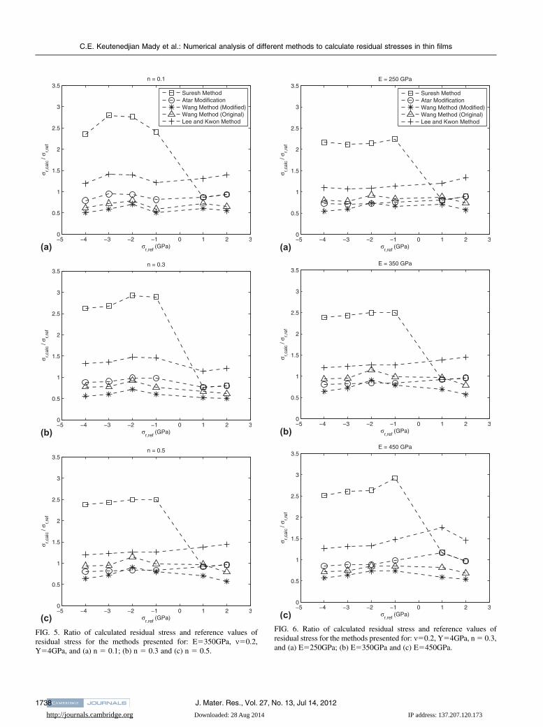
FIG. 5. Ratio of calculated residual stress and reference values ofresidual stress for the methods presented for: E5350GPa, m50.2,Y54GPa, and (a) n 5 0.1; (b) n 5 0.3 and (c) n 5 0.5.
FIG. 6. Ratio of calculated residual stress and reference values ofresidual stress for the methods presented for: m50.2, Y54GPa, n5 0.3,and (a) E5250GPa; (b) E5350GPa and (c) E5450GPa.
C.E. Keutenedjian Mady et al.: Numerical analysis of different methods to calculate residual stresses in thin films
J. Mater. Res., Vol. 27, No. 13, Jul 14, 20121738

http://journals.cambridge.org Downloaded: 28 Aug 2014 IP address: 137.207.120.173
thickness (0.06 lm). In these figures, rr,ref is the referencevalue and rr,calc is the calculated value of residual stress.
A comparison of the methods previously available inthe literature, including the modification on the methodby Wang et al.,16 indicates that in all the cases in Figs. 5–7,the procedure proposed by Suresh and Giannakopoulos10
overestimated the residual stress values when they werecompressive. This method provided values up to threetimes larger than the values imposed in the model. Thisdifference may be related to the existence of the correctionfactor f, since the use of the modification proposed by Ataret al.11 decreased the difference between calculated andimposed results. In Figs. 5–7, the modification proposedby Atar et al.11 underestimated residual stresses when the
stress was compressive. For tensile residual stress, theratio with reference values was closer to 1.
For the Lee and Kwon method,12,13 results indicate anoverestimation of residual stress (tensile and compressive)for the conditions in Figs. 5–7 (in these cases, the ratio wasclose to 1 only for large values of compressive residualstress). This result is possibly explained due to the exis-tence of the 1.5 correction factor in residual stresses cal-culation, as indicated in Eq. (5).
Results obtained using the original Wang et al.method16 indicate that the ratio of calculated and referenceprovided results close to unity in Figs. 5(b) and 5(c) andFigs. 6(a) and 6(b); in the others figures, there was anunderestimation of residual stress results. The modifiedWang et al. method underestimated the value of residualstress in almost all cases. This result was not expectedsince the fitted curves were described more accurately,using general Kick’s law for loading and unloading.
FIG. 7. Ratio of calculated residual stress and reference values ofresidual stress for the methods presented for E5350GPa, m50.3,Y54GPa and n 5 0.3.
FIG. 8. Ratio of calculated residual stress and reference values ofresidual stress for the methods presented for E5350GPa, m50.2,Y58GPa and n 5 0.3.
FIG. 9. Ratio of calculated residual stress and reference values ofresidual stress for the new approach presented for: E5350GPa, m50.2,n50.3 (a) Y54GPa and (b) Y58GPa.
C.E. Keutenedjian Mady et al.: Numerical analysis of different methods to calculate residual stresses in thin films
J. Mater. Res., Vol. 27, No. 13, Jul 14, 2012 1739
http://journals.cambridge.org Downloaded: 28 Aug 2014 IP address: 137.207.120.173
Figures 5–7 indicate that the trends associated withmost of the methods are approximately parallel, which canbe explained by the equations in each case. The equationscorresponding to the Suresh and Giannakopoulos,10 Ataret al.,11 and Lee and Kown12,13 methods are essentiallybased on a difference of applied load divided by area. Theonly difference in these cases is a factor, i.e., the correctionfactor 1/f in the Suresh and Giannakopoulos10 method, 1 inthe Atar et al.11 modification, and 3/(11 p) in the Lee andKown12,13 method [Eqs. (1), (3), and (5)]. In the last case,p was 1 for the conditions analyzed in this work, makingthe factor equal to 1.5.
Results in Fig. 8 were obtained by increasing boththe values of film yield stress and maximum imposedcompressive stress to 8 GPa. In this case, the similarityobserved in the majority of the results in Figs. 5–7 be-came more evident for a larger range of compressiveresidual stress, and again, original Wang et al.16 and Leeand Kwon12,13 had the best correlation with the imposedvalues of compressive residual stresses. In this case, theLee and Kwon12,13 method gave the best result for tensileand compressive residual stresses (ratio close to one).
Results in Fig. 9 were obtained based on Eq. (15). Thisfigure indicates that, both when Y 5 4 GPa [Fig. 9(a)]and Y5 8 GPa [Fig. 9(b)], the error between the values ofH � H0 and the imposed values of compressive stress didnot exceed 20%. The correlation in the case of tensileresidual stresses was worse in both cases, but the errorremained lower than 20% for Y 5 8 GPa [Fig. 9].
The variable in the P–h curve that is most affected byresidual stress is the applied load (the difference betweenstressed and unstressed materials can achieve up to 20%).
The variation of other parameters, such as stiffness (S) andunloading exponent (m), remain below 3%. Thus, goodresults may be obtained with the methods available pre-viously, which are based on this difference in load. However,Fig. 9 seems to indicate that accuracy in residual stressevaluation can be improved if not only the variation in loadis considered but also the variation in the area calculatedusing the Oliver and Pharr method is included.
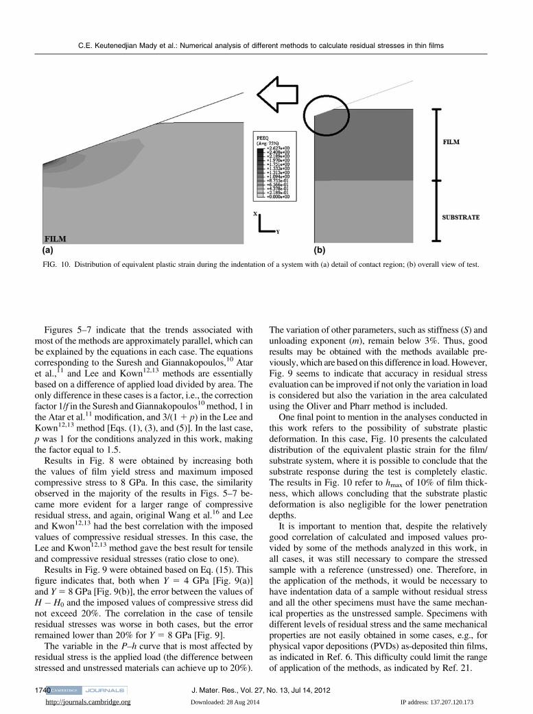
One final point to mention in the analyses conducted inthis work refers to the possibility of substrate plasticdeformation. In this case, Fig. 10 presents the calculateddistribution of the equivalent plastic strain for the film/substrate system, where it is possible to conclude that thesubstrate response during the test is completely elastic.The results in Fig. 10 refer to hmax of 10% of film thick-ness, which allows concluding that the substrate plasticdeformation is also negligible for the lower penetrationdepths.
It is important to mention that, despite the relativelygood correlation of calculated and imposed values pro-vided by some of the methods analyzed in this work, inall cases, it was still necessary to compare the stressedsample with a reference (unstressed) one. Therefore, inthe application of the methods, it would be necessary tohave indentation data of a sample without residual stressand all the other specimens must have the same mechan-ical properties as the unstressed sample. Specimens withdifferent levels of residual stress and the same mechanicalproperties are not easily obtained in some cases, e.g., forphysical vapor depositions (PVDs) as-deposited thin films,as indicated in Ref. 6. This difficulty could limit the rangeof application of the methods, as indicated by Ref. 21.
FIG. 10. Distribution of equivalent plastic strain during the indentation of a system with (a) detail of contact region; (b) overall view of test.
C.E. Keutenedjian Mady et al.: Numerical analysis of different methods to calculate residual stresses in thin films
J. Mater. Res., Vol. 27, No. 13, Jul 14, 20121740
http://journals.cambridge.org Downloaded: 28 Aug 2014 IP address: 137.207.120.173
VI. CONCLUSIONS
In this work, a numerical analysis of instrumentedindentation test on thin film-coated specimens was per-formed as an attempt to use test data to estimate residualstress. For the range of conditions analyzed in the finiteelement simulations, stiffer film (elastic modulus from250 to 450 GPa) onto a more compliant substrate (elasticmodulus of 200 GPa), it was possible to conclude that:
(i) The substrate effect was not significant whenmaximum penetration depth was kept at 4% of film thick-ness and the method provided by Wang et al. providedvalues less dependent of the penetration depth.
(ii) The Suresh and Giannakopoulos10 method overesti-mated the value of compressive residual stresses, but, assuggested by Atar et al.,11 the suppression of factor f im-proved the correlation with the input values;
(iii) The Lee and Kwon method12,13 provided goodcorrelation with the imposed values for some ranges ofmechanical properties; although the original Wang et al.method16 assumed that both the loading and unloadingexponents in Kick’s law were equal to 2, this methodprovided the best correlation with the input values amongthe methods previously available in the literature. Ingeneral, the modified Wang et al. method underestimatedthe residual stress values.
(iv) The method based on the difference in hardness(calculated from the Oliver and Pharr method) of a spec-imen with and without residual stress provided goodcorrelation with the input values.
(v) One limitation of all methods is the necessity of havinga reference unstressed sample with the same mechanicalproperties as the tested one.
ACKNOWLEDGMENTS
The authors acknowledge FAPESP (São Paulo Re-search Foundation) for Grant No. 2007/04731-9 andCNPq (National Council of Technological and ScientificDevelopment) for Grants 303780/2008-8, 150966/2009-1,and 141259/2007-8.
REFERENCES
1. T.Y. Tsui, W.C. Oliver, and G.M. Pharr: Influences of stress on themeasurement of mechanical properties using nanoindentation: PartI. Experimental studies in an aluminum alloy. J. Mater. Res. 11, 752(1996).
2. A. Bolshakov, W.C. Oliver, and G.M. Pharr: Influences of stress onthe measurement of mechanical properties using nanoindentation:Part II. Finite element simulations. J. Mater. Res. 11, 760 (1996).
3. G. Sines and R. Carlson: Hardness measurements for determinationof residual stresses. ASTM Bull. 180, 35 (1952).
4. W.C. Oliver and G.M. Pharr: Improved technique for determininghardness and elastic modulus using load and displacement sensingindentation experiments. J. Mater. Res. 7, 1564 (1992).
5. W.C. Oliver and G.M. Pharr: Measurement of hardness andelastic modulus by instrumented indentation: Advances in
understanding and refinements to methodology. J. Mater. Res.19, 3 (2004).
6. C.E.K. Mady, S.A. Rodriguez, A.G. Gomez, and R.M. Souza:Effects of mechanical properties residual stress and indenter tipgeometry on instrumented indentation data in thin films. Surf. Coat.Technol. 205, 1393 (2010).
7. P. Larsson: On the mechanical behavior at sharp indentation ofmaterials with compressive residual stresses. Mater. Des. 32, 1427(2011).
8. L. Ling, S. Long, Z. Ma, and X. Liang: Numerical study on theeffects of equi-biaxial residual stress on mechanical properties ofNickel film by means of nanoindentation. J. Mater. Sci. Technol.26, 1001 (2010).
9. J. Jang: Estimation of residual stress by instrumented indentation:A review. J. Ceram. Process. Res. 10, 391 (2009).
10. S. Suresh and A.E. Giannakopoulos: A new method for estimatingresidual stresses by instrumented sharp indentation. Acta Mater. 46,5755 (1998).
11. E. Atar, C. Sarioglu, U.Demirler, E. Sabri Kayali, andH. Cimenoglu:Residual stress estimation of ceramic thin films by x-ray diffractionand indentation techniques. Scr. Mater. 48, 1331 (2003).
12. Y.H. Lee and D. Kwon: Measurement of residual-stress effect bynanoindentation on elastically strained (100)W. Scr. Mater. 49, 459(2003).
13. Y.H. Lee and D. Kwon: Estimation of biaxial surface stress by instru-mented indentation with sharp indenters. Acta Mater. 52, 1555 (2004).
14. S. Carlsson and P.L. Larsson: On the determination of residualstress and strain fields by sharp indentation testing: Part I:Theoretical and numerical analysis. Acta Mater. 49, 2179 (2001).
15. S. Carlsson and P.L. Larsson: On the determination of residualstress and strain fields by sharp indentation testing: Part II:Experimental investigation. Acta Mater. 49, 2193 (2001).
16. Q. Wang, K. Ozaki, H. Ishikawa, S. Nakano, and H. Ogiso:Indentation method to measure the residual stress induced by ionimplantation. Nucl. Instrum. Methods Phys. Res. 242, 2823 (2006).
17. M. Zhao, X. Chen, J. Yan, and A. Karlsson: Determination ofuniaxial residual stress and mechanical properties by instrumentedindentation. Acta Mater. 54, 2823 (2006).
18. J. Lee, H. Lee, H. Hyun, and M. Kim: Numerical approaches andexperimental verification of the conical indentation techniques forresidual stress evaluation. J. Mater. Res. 25, 2212 (2010).
19. B. Taljat and G.M. Pharr: Measurement of residual stresses by loadand depth sensing spherical indentation, in Thin Films: Stresses andMechanical Properties VIII, edited by R. Vinic, O. Kraft, N. Moody,and E. Shaffer (Mater. Res. Soc. Symp. Proc. 594, Warrendale, PA,2000), p. 519.
20. J.G. Swadener, B. Taljat, and G.M. Pharr: Measurement of residualstress by load and depth sensing indentation with sphericalindenters. J. Mater. Res. 16, 2091 (2001).
21. C.M. Lepienski, G.M. Pharr, Y.J. Park, T.R.Watkins, A.Misra, andX. Zhang: Factors limiting the measurement of residual stresses inthin films by nanoindentation. Thin Solid Films 447, 251 (2004).
22. M. Choi, K. Lee, J. Kim, K. Kim, and D. Kwon: Application ofinstrumented indentation technique to estimate strength and re-sidual stress, in 10th Symposium on Recent Advancements in theTheory and Practice of Hardness Measurement (Hardmeko Proc.Tsukuba, Japan, 2007); p. 24.
23. S.A. Rodríguez Pulecio, M.C. Moré Farias, and R.M. Souza:Analysis of the effects of conical indentation variables on theindentation response of elastic–plastic materials through factorialdesign of experiment. J. Mater. Res. 24, 1222 (2009).
24. W.R. LaFontaine, C.A. Paszkiet, M.A. Korhonen, and C-Y. Li:Residual stress measurements of thin aluminum metallizations bycontinuous indentation and x-ray stress measurement techniques.J. Mater. Res. 6, 2084 (1991).
C.E. Keutenedjian Mady et al.: Numerical analysis of different methods to calculate residual stresses in thin films
J. Mater. Res., Vol. 27, No. 13, Jul 14, 2012 1741


![Brief Conference Program - Shopify...[WJ2] (Invited speaker) A study on deformation of magnesium using instrumented indentation W.J. Poole (The University of British Columbia) with](https://static.fdocuments.in/doc/165x107/606c9df5a272cf5cbd2e8a63/brief-conference-program-shopify-wj2-invited-speaker-a-study-on-deformation.jpg)


![108 Review of Instrumented Indentation - NIST · 108, 249-265 (2003)] Review of Instrumented Indentation Volume 108 Number 4 July-August 2003 Mark R. VanLandingham1 National Institute](https://static.fdocuments.in/doc/165x107/5fa5dd0497bee51ee0357ff0/108-review-of-instrumented-indentation-nist-108-249-265-2003-review-of-instrumented.jpg)


