
Nucleus Paging Transmitters Product Description 1 - …braddye.com/nucleus/Nucleus Tx detail.pdf ·...
33
December 1997 3 Nucleus Paging Transmitters Product Description 1 Introduction to Motorola’s Nucleus Paging Transmitters, 2 Features, 4 Components, 8 Optional Features and Equipment, 23 Physical Packaging and Environmental Specifications, 30
Transcript of Nucleus Paging Transmitters Product Description 1 - …braddye.com/nucleus/Nucleus Tx detail.pdf ·...

Nucleus Paging Transmitters ProductDescription 1
Introduction to Motorola’s Nucleus Paging Transmitters, 2
Features, 4
Components, 8
Optional Features and Equipment, 23
Physical Packaging and Environmental Specifications, 30
December 1997 3

Introduction to Motorola’s Nucleus Paging Transmitters Nucleus Paging Transmitters Product Description
Introduction to Motorola’s Nucleus Paging Transmitters
Motorola’s Nucleus paging transmitters combine advanced technology, proven reliability, andexceptional customer convenience. Designed to meet the needs of the world wide paging marketplace,Nucleus transmitters embrace a full complement of frequency and power options.
The Nucleus transmitter family consists of two models—the Nucleus and Nucleus II (see Figure 1)..
Figure 1: Nucleus and Nucleus II
Nucleus transmitters operate in various frequency bands from 132 to 941 MHz and are available instandard-power (25–125 W) and high-power (300–350 W) models.
Nucleus II transmitters operate in the 927– 941MHz frequency band and are available in high-power(250-300 W) models only.
0F90
SR
H-2
0
POWER SUPPLY
WARNING DISCONNECT battery (if battery equipped)and turn OFF power supply before removingor inserting any module.
FAIL
ON
CONTROL
ON
FAIL
STBY
ALARM
REF.
PORT
TX LOCK
PA FULL
PA LOW
PA FAIL
705S
RH
-03a
POWER AMPLIFIER EXCITER
1 2 3
4 5 6
7 8 9
0
EXIT TOG ENT
Reset
Nucleus Nucleus II
4 December 1997

Nucleus Paging Transmitters Product Description Introduction to Motorola’s Nucleus Paging Transmitters
A complete listing of the available frequency bands and power ranges for the Nucleus and Nucleus IIis provided below (see Table 1 and Table 2).
1. Measured at output of power amplifier (PA) cable.
Table 1: Nucleus Transmitters
Frequency(MHz)
Power Output (W)New Model Number(Old Model Number)
Dimensions(H x W x D)
Weight
132–154 (VHF) 125 W (variable to 20 W)PT1148A standard power(T5481 with X195AA)
8.75 x 19 x 20 in.23 x 48 x 51 cm
60 lb27 kg
132–154 (VHF) 25 W (variable to 5 W)PT1146A standard power(T5481 with X330AC)
8.75 x 19 x 20 in.23 x 48 x 51 cm
60 lb27 kg
144–160 (VHF) 350 W (variable to 100 W)PT1150A high power(T5482 with X830AD)
14 x 19 x 20 in.35 x 48 x 51 cm
105 lb48 kg
150–174 (VHF) 125 W (variable to 20 W)PT1149A standard power(X5481 with X195AB)
8.75 x 19 x 20 in.23 x 48 x 51 cm
60 lb27 kg
150–174 (VHF) 25 W (variable to 5 W)PT1147A standard power(T5481 with X330AC)
8.75 x 19 x 20 in.23 x 48 x 51 cm
60 lb27 kg
158–174 (VHF) 350 W (variable to 100 W)PT1151A high power(T5482 with X830AE)
14 x 19 x 20 in.35 x 48 x 51 cm
105 lb48 kg
276–284 125 W (variable to 20 W)PT1142A standard power(T5481 with X213AA)
8.75 x 19 x 20 in.23 x 48 x 51 cm
60 lb27 kg
276–284 300 W (variable to 100 W)PT1143A high power(T5482 with X214AA)
14 x 19 x 20 in.36 x 48 x 51 cm
105 lb48 kg
438–470 (UHF) 100 W (variable to 25 W)PT1158A standard power(T5481 with X640AH)
8.75 x 19 x 20 in.23 x 48 x 51 cm
60 lb27 kg
929–941 100 W (variable to 20 W)PT1161A standard power(T5481 with X660AB)
8.75 x 19 x 20 in.23 x 48 x 51 cm
60 lb27 kg
Table 2: Nucleus II Transmitters
Frequency(MHz)
Power Output (W) Model NumberDimensions(H x W x D)
Weight
929–941 300 W (variable to 100 W)1PT1104 high power(T5482 x/X201AA)
14 x 19 x 20 in.36 x 48 x 51 cm
105 lb48 kg
929–941 250 W1PT1105 high power with triplecirculator(PT1104 with X677)
14 x 19 x 20 in.36 x 48 x 51 cm
105 lb48 kg
929–941 300 W (variable to 100 W)1PT1173 high power(42–72 Vdc power supply)
14 x 19 x 20 in.36 x 48 x 51 cm
105 lb48 kg
929–941 300 W (variable to 100 W)1PT1174 high power(23–34 Vdc)
14 x 19 x 20 in.36 x 48 x 51 cm
105 lb48 kg
December 1997 5

Introduction to Motorola’s Nucleus Paging Transmitters Nucleus Paging Transmitters Product Description
1. Asia model designations refer to a Nucleus transmitter in combination with a controller.
Table 3: Nucleus Transmitters—Asia Model Designations1
Frequency(MHz)/Control
Power Output (W) Model NumberDimensions(H x W x D)
Weight
132–154 (VHF)RF-Baton!
125 W (variable to 20 W) PT1231A8.75 x 19 x 20 in.23 x 48 x 51 cm
60 lb27 kg
132–154 (VHF)NAC
125 W (variable to 20 W) PT1232A 8.75 x 19 x 20 in.23 x 48 x 51 cm
60 lb27 kg
132–154 (VHF)C-NET
125 W (variable to 20 W))PT1233A 14 x 19 x 20 in.
35 x 48 x 51 cm105 lb48 kg
150–174 (VHF)RF-Baton!
125 W (variable to 20 W)PT1236A 8.75 x 19 x 20 in.
23 x 48 x 51 cm60 lb27 kg
150–174 (VHF)NAC 125 W (variable to 20 W)
PT1237A 8.75 x 19 x 20 in.23 x 48 x 51 cm
60 lb27 kg
150–174 (VHF)C-NET
125 W (variable to 20 W))PT1238A 8.75 x 19 x 20 in.
23 x 48 x 51 cm60 lb27 kg
276–286RF-Baton!
125 W (variable to 20 W)PT1226A 8.75 x 19 x 20 in.
23 x 48 x 51 cm60 lb27 kg
276–286NAC
125 W (variable to 20 W))PT1127A 8.75 x 19 x 20 in.
23 x 48 x 51 cm60 lb27 kg
276–286C-NET
125 W (variable to 20 W)PT1128A 8.75 x 19 x 20 in.
23 x 48 x 51 cm60 lb27 kg
929–941C-NET
100 W (variable to 20 W)PT1143A 8.75 x 19 x 20 in.
23 x 48 x 51 cm60 lb27 kg
6 December 1997

Nucleus Paging Transmitters Product Description Features
Features
In order to attain our goal of 100 percent customer satisfaction, the Motorola paging infrastructureteam has made continuous quality improvements the centerpiece of its product design effort. We wantto be sure our products deliver (and continue to deliver) what our customers want—high reliability,reduced cost, and technologically advanced performance. Features that have been put in the Nucleusproduct line as a result of our continuing focus on customer needs are described below.
High-Speed Performance For Maximized Capacity
The transmitters that make up the Nucleus line allow far more subscribers per channel thancompeting products. A Nucleus transmitter can seamlessly employ paging signaling schemes of up to6400 bps with 4-level modulation when using the FLEX protocol or process 2-level modulation up to3200 bps to service POCSAG and GSC pagers. The 2-level deviations can be set by the user and arevery flexible with settings from 1 Hz to 5000 Hz. The 4-level deviations are factory set for FLEX 6400.The frequency offsets also can be set by the user for even more flexibility in the field.
The Nucleus product line features a digital signal processor-based modulator that provides precisewaveshaping for high-speed FLEX operation. The microprocessor sends the deviation information tothe modulator, which sets the modulation electronically. This method ensures a high degree ofaccuracy over an extended time period.
Reliability
The Dual Device Modules (DDMs) that make up the power amplifier section of the Nucleus productsare built in a parallel architecture, which produces more reliable operation. The individual DDMs aredesigned to have a very high level of reliability, but if one does fail the station can continue to transmitpages, although at a lower power output.
Changes have been made to the routing of cooling air within the Nucleus products in order toimprove the overall reliability of electrical components. The components in the power supplies havebeen isolated from the cooling air flow so that the air only flows over the heat sinks. This keeps thecomponents cleaner which and thus their performance life is maximized. In the power amplifiers, thegraphite flange to which t the devices are attached is an excellent heat dissipater. Once the heat ispulled away from the device, it is pulled down through the aluminum heat sink to the fins where fansblow cool air from the front of the station to the rear. This front-to-back cooling design allows thestation to be thermally independent from other equipment.
Robust Design
The Nucleus products are designed to perform reliably in unheated and uncooled environments, andin unfavorable atmospheric conditions such as salt air and high humidity.
All of the models that make up the Nucleus line are put through several months of rigorousenvironmental testing that includes salt, fog, temperature-cycling, dust, vibration, electrostaticdischarge, impact, line transients, and temperature shock. The goal of this testing program is to ensurenot only conformance to Motorola's stringent product quality specifications, but to also guarantee ahigh level of customer satisfaction with the way the products perform in actual field conditions.
December 1997 7

Features Nucleus Paging Transmitters Product Description
Efficiency
Motorola considers efficiency to be a major performance objective for its transmitters. Therefore, thetransmitters that make up the Nucleus line are continually updated and improved. The design of thepower supply, for example, was recently improved to make it 10 percent more efficient. The AC-to-DCconverter circuitry has also been improved to be more robust and efficient.
The 300-W, 900-MHz power amplifier also has been made more efficient. The design of the combinercircuitry has been improved, which decreases the amount of power lost in the RF runners. The triplestage circulator was also redesigned for more efficiency and less loss. The low pass filter and internalwattmeter have also been enhanced to be more efficient and to draw less current and therefore lessheat, which makes them last longer.
Modularity and Field Replaceable Units
Fundamental to the success of the Nucleus product line is its building block design. Each function ofthe transmitter is located in a distinct, easily removable module. By isolating the functions of thetransmitter, several of the modules are common to different frequency bands and power levels. Thismodular approach offers several advantages:
• Reduces spare parts requirements for operators using different models in their network
• Allows easy upgrading as you grow your network
• Facilitates easy installation and service because technicians only need to learn one paging stationdesign
• Allows next-generation diagnostics and maintenance features
The station alarms inform the technician of a problem in easy to understand terms such as “PowerSupply Failed”. Each module is an independent Field Replaceable Unit and is clearly labeled byfunction. With the exception of the power amplifier, all modules attach to the backplane by means ofgold-plated connectors that can be quickly disengaged. (The power amplifier is connected by a cable,which is also easily disengaged.) In the event of a failure, the technician can go to the site with theproper replacement module in hand, quickly replace the failed module, and immediately verify thatthe failure has been corrected by checking the LEDs on the module’s front panel.
Compact Size
The compact size of the Nucleus transmitters provides easy installation and reduces facility costs. Thehigh-power models are 14 inches tall and weigh 105 lbs. in a rack-mount configuration. Standard-power models are 8.75 inches tall and weigh 60 lbs.
Power Control Software and Auto Power Calibration
In the Nucleus II, the transmitter is self-calibrating, using power control software to maximize thepower output setting. This power control software helps protect the power amplifier by making surethat the station is always transmitting at or below the maximum power output level. There is awattmeter at the output of the power amplifier that constantly monitors and sends the performance
8 December 1997

Nucleus Paging Transmitters Product Description Features
information back to the power control software, which prevents an overdrive condition. To makeinstallation easier, the maximum power settings for the station are set at the factory. This eliminatesthe guesswork and possible errors that may occur with setting the power manually.
Another feature of electronically controlled power output is the ability to offer a battery revert option.When battery revert is selected, the control section of the transmitter, including the SCM, the NIU andthe exciter, is backed up with battery power. This will allow the Nucleus II to maintain NIUsynchronization and alarm reporting capabilities in the event of a power failure.
Multiple Power Configurations and Channel Mapped Power
If a service provider has two frequencies (i.e., nationwide and regional licenses), he can set the poweroutput for each channel individually. The system will switch channels and change power levelsbetween the channels seamlessly. This is advantageous if the required effective radiated power differsbetween the two channels.
Alarm Reporting
All Nucleus models support a wide variety of alarms for quick and easy trouble-shooting (see Table 4).
Table 4: Nucleus Alarms
Alarm Name Interpretation ProgrammableCondition that Clearsthe Alarm
Low Forward PowerForward power is below athreshold
YesStation keys at correctpower (above threshold)
High Reflected PowerReflected power is above athreshold
YesStation keys at correctpower (below threshold)
External Low ForwardPower
Forward power is below athreshold measured at the externalwattmeter (requires externalwattmeter)
YesStation keys at correctpower (above threshold)
External High ReflectedPower
Reflected power is above athreshold measured at the externalwattmeter (requires externalwattmeter)
YesStation keys at correctpower (below threshold)
PA Fan Power amplifier fan has failed No Fan is operational
Synthesizer Out of LockSynthesizer is not locked with theprogrammed frequency
NoSynthesizer locks on theprogrammed frequency
Battery RevertSystem has reverted to batterypower
NoStation switches to ACpower
System Timer Expired System timer has expired NoSystem keys, or resetfrom the ALRM menu
PA FailSystem has determined that thepower amplifier has failed
NoPower amplifier isfunctional
December 1997 9

Features Nucleus Paging Transmitters Product Description
Station Reset System has performed a reset No Cleared from ALRM menu
High Stability ReferenceFailure
High stability reference oscillator orthe ultra high stability referenceoscillator has failed
No
High stability referenceoscillator or the ultra highstability referenceoscillator is functional
Alignment IDMismatched
Station control module and exciterare not aligned
No Cleared from ALRM menu
High Forward PowerPower output poorly aligned;forward power 5% more than therated amplifier power
NoPower is calibrated
PA Not AlignedPower amplifier is not aligned withstation control module
NoStart-up occurs withmatched pair
Exciter Setup FailureProblem occurred during excitermodule setup or problem withreceiver module
NoExciter starts withoutproblem
Table 4: Nucleus Alarms
Alarm Name Interpretation ProgrammableCondition that Clearsthe Alarm
10 December 1997

Nucleus Paging Transmitters Product Description Components
Components
All Nucleus models are installed in a standard 19-inch EIA electronics cabinet and contain (with theexception of the NAC model) the modules listed below.
• Station control module (SCM)—The SCM consists of a front panel module and a circuit board.The front panel module contains displays and a keyboard that are used by the operator to inputconfiguration and alarm settings. The circuit board, which is called the station control board,supports operator input functions as well as processing incoming paging signals from thecontroller. (On models with the NAC option installed, this component is called the NAC module.See the description under Options.)
• Exciter—The exciter converts the digital information into a modulated RF signal with carrierfrequency for the transmitter.
• Power supply—The power supply provides +5Vdc, +14Vdc, and +28Vdc power. High-powerunits have two power supplies.
• Power amplifier (PA)—The power amplifier enhances the RF signal to high-power output andsends it to the antenna.
• Reference module—The reference module provides a known reference signal to stabilizetransmitter output.
• Transmitter controller—The transmitter controller provides an interface to the network controldevice. (This module is not applicable to units withthe NAC option installed. Transmittercontroller functions for NAC models are included on the NAC board.) The transmitter controlleris one of the following:
– RF-Baton! (RF-B!) transmitter controller (requires WIB board)
– Internal Network Interface Unit (NIU)
– External NIU (requires WIB board)
In addition, the optional receiver module, which can function either as a link receiver or as a receivermonitor, may be included as part of the transmitter package. (See description of receiver moduleunder Options.)
December 1997 11

Components Nucleus Paging Transmitters Product Description
The arrangement of components for a standard-power unit is shown in Figure 1-2, and thearrangement for a high-power unit is shown in Figure 1-3.
Figure 1-5: Standard-Power Nucleus Hardware Configuration
POWER SUPPLY
WARNING DISCONNECT battery (if battery equipped)and turn OFF power supply before removingor inserting any module.
FAIL
ON
CONTROL
ON
FAIL
STBY
ALARM
REF.
PORT
TX LOCK
PA FULL
PA LOW
PA FAIL
705S
RH
-03a
POWER AMPLIFIER EXCITER
1 2 3
4 5 6
7 8 9
0
EXIT TOG ENT
Reset
Power Amplifier Exciter Power Supply Station Control Reference ReceiverModule Module Module ModuleModuleModule
Station Control Board(behind front panel)
12 December 1997

Nucleus Paging Transmitters Product Description Components
Figure 1-6: High-Power Nucleus Hardware Configuration
Station Control Module
The SCM has several functions:
• Controls the transmitter including setting all operating parameters
• Provides the mode, clock, and data to the exciter
• Polls all internal modules to determine their status and reports alarm information to the networkcontroller
POWER SUPPLY
WARNING DISCONNECT battery (if battery equipped)and turn OFF power supply before removingor inserting any module.
FAIL
ON
CONTROL REFERENCE
ON
FAIL
STBY
ALARM STATUS
C-NET
REF.
PORT
TX LOCK
PA FULL
PA LOW
PA FAIL
EXCITERPOWER SUPPLY
WARNING DISCONNECT battery (if battery equipped)and turn OFF power supply before removingor inserting any module.
FAIL
ON
1 2 3
4 5 6
7 8 9
0
EXIT TOG ENT
Reset
0F55
SR
H-0
4
POWER AMPLIFIERA
Power Supply ExciterModule
Power SupplyModule #1Module #2
Station ControlModule
ReferenceModule
ReceiverModule
Power AmplifierModule
Station Control Board(behind front panel)
Network Interface Unit(behind front panel)
December 1997 13

Components Nucleus Paging Transmitters Product Description
• Maintains communication with the receiver
The SCM consists of an SCM front panel and a station control board. Each front panel includes a 15-pushbutton keypad and an LED display (See Figure 1-7). An operator can enter commands andconfiguration data for the transmitter through the keypad and can confirm data on the display.
Figure 1-7: Station Control Module
The station control board includes a digital signal processor (DSP), a DSP application-specificintegrated circuit (DSP ASIC), and an ASIC interface (See Figure 1-8). The output of the station controlboard consists of three signals:
• VCO MOD, which controls the impulse response of the exciter
• REF MOD, which modulates the reference frequency for long-term deviation accuracy
• 16.8 MHz REF, which provides a 16.8-MHz reference signal to the exciter
The DSP also contains a splatter filter to prevent the transmit signal from interfering with adjacenttransmit channels. This feature gives the Nucleus paging station optimal simulcast performance. Avariety of splatter filter designs can be configured by the operator through the keypad on the SCMfront panel.
The host microprocessor controls the transmission of pages. The host microprocessor reads Nucleuspaging station software and configuration data from memory. For example, the power level that is tobe applied to the channel is controlled by software settings provided through the keypad on the SCMfront panel. The microprocessor exchanges addresses and data with the host ASIC. The host ASIC
CONTROL
ON
FAIL
STBY
ALARM
REF.
PORT
1STN
2RX
3TX
4OPT1
5OPT2
6ASET
7STAT
SERV
8CNFG
9ALMS
ALGN0DIS
ENTTOG
Reset
Light Emitting Diode(LED) Display
Keypad
Alarm LEDs
Reference Frequency
Serial Port
2F05
SR
H-2
8
14 December 1997

Nucleus Paging Transmitters Product Description Components
communicates with memory and the SCM front panel through a serial peripheral interface (SPI) bus.For module status and alarm reporting, the SPI bus communicates with the other modules on thebackplane
Figure 1-8: Station Control Board Block Diagram
Controller
Memory
DSP ASICInterface DSP ASIC Audio Interface
Circuitry
Digital SignalProcessor
(DSP)
HostMicroprocessor Host ASIC
Buffer
Keypad Buffer
Synchronous LocalControl (SyLC)
Audio InterfaceBus
VCO MOD
REF MOD
16.8 MHz 16.8 MHz
16.8 MHzReferenceOscillator
Reference Input (RF-Baton! TransmitterController, Reference Module, or External Frequency Reference)
SPI Bus
SPI Bus
SPI Bus
Control Front Panel
Station Control Board
2F05
SR
H-0
2
December 1997 15
Components Nucleus Paging Transmitters Product Description
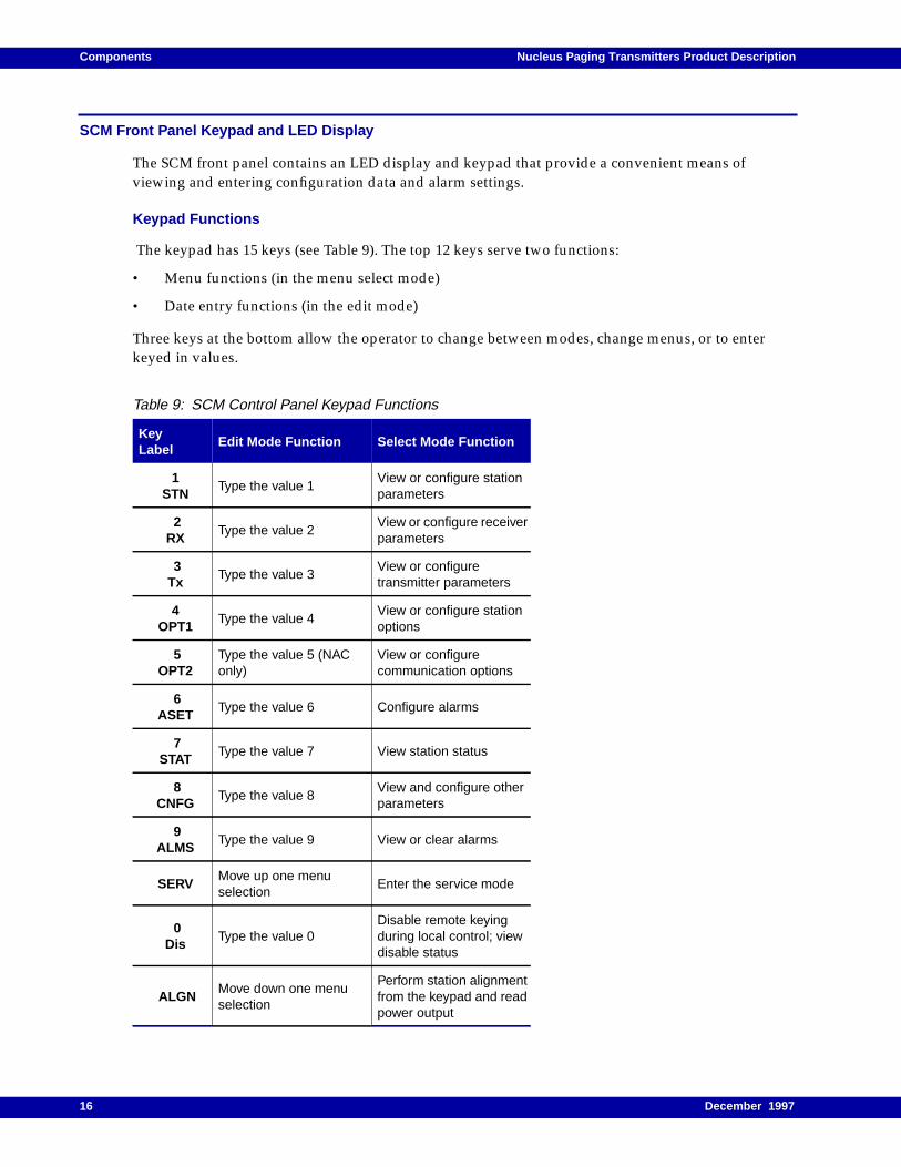
SCM Front Panel Keypad and LED Display
The SCM front panel contains an LED display and keypad that provide a convenient means ofviewing and entering configuration data and alarm settings.
Keypad Functions
The keypad has 15 keys (see Table 9). The top 12 keys serve two functions:
• Menu functions (in the menu select mode)
• Date entry functions (in the edit mode)
Three keys at the bottom allow the operator to change between modes, change menus, or to enterkeyed in values.
Table 9: SCM Control Panel Keypad Functions
KeyLabel
Edit Mode Function Select Mode Function
1STN
Type the value 1View or configure stationparameters
2RX
Type the value 2View or configure receiverparameters
3Tx
Type the value 3View or configuretransmitter parameters
4OPT1
Type the value 4View or configure stationoptions
5OPT2
Type the value 5 (NAConly)
View or configurecommunication options
6ASET
Type the value 6 Configure alarms
7STAT
Type the value 7 View station status
8CNFG
Type the value 8View and configure otherparameters
9ALMS
Type the value 9 View or clear alarms
SERVMove up one menuselection
Enter the service mode
0Dis
Type the value 0Disable remote keyingduring local control; viewdisable status
ALGNMove down one menuselection
Perform station alignmentfrom the keypad and readpower output
16 December 1997

Nucleus Paging Transmitters Product Description Components
SCM Front Panel LEDs
The SCM front panel has four LEDs for the SCM (see Table 10). All LEDs momentarily light duringpower-up or reset
Exciter
The exciter generates modulated RF paging signals at the appropriate messaging frequency and sendsthe messaging signals to the PA. To do this, the exciter mixes the messaging data with the carrierfrequency. The exciter is frequency-specific for the transmitter. The exciter consists of a referencemodulator, a synthesizer, a voltage-controlled oscillator (VCO), an RF switch circuit, and a transmitterpower circuit (see Figure 1-11). The exciter runs is controlled by its own microprocessor. The excitersynthesizer and microprocessor communicate with the host ASIC on the SCM through the SPI bus.
EXITReturn to the menu selectmode
Move one menu level
TOGToggle between the editmode and the menuselect mode
ENT Store keyed-in valuesMove in one menu levelor begin an edit session
Table 10: SCM Control Panel LED Functions and Definitions
LED Name Color On Flashing Off
On Green SCM fully functional Not used SCM failure
Fail Red SCM failureSoftware checksumfailure
Fully functional SCM
Disable Red
Disabled by remotekeying (maintenanceaccess or paging accessdisabled)
Shorted DRAM addresslines are open
Enabled and fullyfunctional SCM
Alarm RedActive station alarm (seeAlarms menu)
Shorted DRAM addresslines
Fully functional SCM
Table 9: SCM Control Panel Keypad Functions
KeyLabel
Edit Mode Function Select Mode Function
December 1997 17

Components Nucleus Paging Transmitters Product Description
Figure 1-11: Exciter Block Diagram
The reference modulator receives the 16.8-MHz reference signal from the reference oscillator on theSCM. The reference modulator receives the reference modulation signal from the audio interfacecircuitry on the SCM. The reference modulator combines the two signals and sends the modulatedreference signal to the synthesizer. The synthesizer compares the modulated reference signal with thefeedback sample from the VCO. The synthesizer increases or decreases the frequency by generatingcorrection pulses. The synthesizer feeds the correction pulses to an internal charge pump. The chargepump creates a DC correction voltage.
The synthesizer uses the correction voltage to correct the output to the RF switch circuit. The correctedfrequency passes to the VCO. The VCO also receives audio and data modulation (VCO MOD) fromthe audio interface circuit on the station control board. The VCO uses this information to create amodulated low-power RF carrier signal. The modulated low-power RF carrier signal then passesthrough an impedance, amplification, and filtering circuit and then to the PA. The excitermicroprocessor generates a Tx Enable signal and sends it to the RF switch circuit upon properoperation.
When it receives a key command, the microprocessor also generates a PA Key signal and a modulatedsignal. It transmits these to the transmitter power control circuitry in case there is any need to providea power cutback, for example, if there exists a cutback condition in the station (such as a hightemperature condition).
The transmitter power control circuitry generates the power control voltage. The transmitter powercontrol circuitry reads the Tx Forward Power Detect signal and uses it to modify the power controlvoltage.
ReferenceModulator
Synthesizer VCO
MicroprocessorTx PowerControlCircuitry
RF SwitchCircuitry
ImpedanceAmplification
andFiltering Circuit
Tx EnablePower Control Voltage
Modulated RF
+13 dBm
Tx Forward Power DetectPA Key
SPI Bus
VCO MOD
REF MOD
16.8 MHz Ref
2F05
SR
H-0
3
To PA Module
From StationControl Board
Exciter Module
18 December 1997

Nucleus Paging Transmitters Product Description Components
Exciter LEDs
The LEDs on the exciter front panel are described below (See Table 12).
Power Amplifier
The power amplifier (PA) takes the modulated RF messaging signal and amplifies it in preparation fortransmission. The structure of the PA depends on the station power level: standard-power Nucleuspaging station (100 to 125 W) or high-power Nucleus paging station (250 to 350 W).
The output power level for the PA (at full power) varies with the frequency ranges for the PA, theexciter, and the transmitter (see Tables 1-1 and 1-2).
Power Amplifier for a Standard Power-Nucleus Paging Station
The standard-power PA consists of the following elements (see Figure 1-13).
• Intermediate power amplifier
• Driver power amplifier
• Final power amplifier number 1
• Circulator
• Harmonic filter/coupler
Table 12: Exciter LED Functions and Definitions
LED Name Color Lighted Off
TX Lock GreenExciter synthesizer islocked; exciter is fullyfunctional.
Synthesizer is out of lockor +5V or +14.2V or bothare absent
PA Full GreenTransmitter is keyed andPA output power is atexpected power level
PA not keyed or PA keyedbut PA output power ismore than 95% ofexpected power
PA Low Yellow
Transmitter is keyed andPA output power is lessthan expected power levelbut not shut down
PA not keyed or PA keyedand PA output power isless than 95% ofexpected power
PA Fail(On)
Red
No PA output power(example: PA shutdownmode), LED status islatched (status duringcurrent key or for previouskey), fault in one or moreof the PA fans, or final PAVSWR Alarm is activated
PA output power is atexpected level or atspecific cutback levels(any level other thanshutdown), LED status islatched (status duringcurrent key or for previouskey)
PA Fail(Flashing)
Red PA test mode is active PA is functioning normally
December 1997 19

Components Nucleus Paging Transmitters Product Description
• Impedance amplification and filtering circuit
Figure 1-13: PA Block Diagram for a Standard Power Nucleus Station
In the standard-power system, the modulated RF passes through the intermediate power amplifier,the driver power amplifier, and the final amplifier number 1. A power control voltage signal modifiesthe performance of each chip to ensure the proper signal processing. The circulator provides 20 dBisolation between the power amplifier circuitry and the transmit antenna system. The circulatorjunction allows forward RF energy to pass through to the output and routes reflected RF energy to the50-Ohm load.
If the heat sink temperature exceeds a preset threshold (set at approximately 45˚ C), the PA reducesoutput. If overheating persists until it reaches 60˚ C, the PA shuts down completely.
An internal wattmeter sends RF power and voltage standing-wave ratio (VSWR) information to thefront panel. The SPI bus transmits this wattmeter reading to the SCM.
An option for the standard-power system is a double circulator that provides a low-loss path for RFsignals from the combined output to the low-pass harmonics filter and wattmeter, resulting in anadditional 20dB of isolation. The double circulator absorbs high reflected RF signals from the antennaport, thus preventing the power amplifier from being damaged. The harmonic filter reduces circulatorharmonics. The signal passes through an impedance amplification and filtering circuit on its way tothe transmit antenna.
Power Amplifier for a High Power Nucleus Paging Station
The high power supply consists of the following elements (see Figure 2-2):
• Intermediate power amplifier
Circulator
50 ohmLoad
Transmit Antenna
2F05
SR
H-0
5
Power Amplifier Module
Harmonic FilterCoupler
ImpedenceAmplification &Filtering Circuit
Modulated RF
Power Control Voltage
IntermediatePower Amplifier
DriverPower Amplifier
Final PowerAmplifier #1
20 December 1997

Nucleus Paging Transmitters Product Description Components
• Driver power amplifier
• Power splitter
• Three final power amplifiers
• Power combiner
• Circulator
• Harmonic filter/coupler
• Impedance amplification and filtering circuit
Figure 1-14: PA Block Diagram for a High Power Nucleus Station
The modulated RF passes through the intermediate power amplifier and the driver power amplifierinto the power splitter. The power splitter divides the power output into three and sends the threeoutputs to the final power amplifiers. Each power amplifier sends its output to a power combiner andthen to a circulator. Depending on the model, the high power Nucleus paging station has a double ortriple circulator option that provides a low-loss path for RF signals from the combined output to thelow-pass harmonics filter and wattmeter. The double or triple circulator absorbs high reflected RFsignals from the antenna port. This arrangement prevents the power amplifier from being damaged.
The circulator provides 20 dB of isolation between the power combiner circuitry and the transmitantenna system. The circulator junction allows forward RF energy to pass through to the output androutes reflected RF energy to the 50-Ohm load.
If the heat sink temperature exceeds a preset threshold, the PA reduces output. If overheating persists,the PA shuts down completely. The harmonic filter reduces circulator harmonics. An internalWattmeter sends RF power VSWR information to the front panel. This Wattmeter reading istransmitted on the SPI bus to the SCM.
IntermediatePower Amplifier
DriverPower Amplifier
Final PowerAmplifier #1
Circulator
50 ohmLoad
Transmit Antenna
2F05
SR
H-0
4
Power Amplifier Module
PowerSplitter
Final PowerAmplifier #2
Final PowerAmplifier #3
PowerCombiner
Harmonic FilterCoupler
ImpedenceAmplification
andFiltering Circuit
Modulated RF
Power Control Voltage
December 1997 21

Components Nucleus Paging Transmitters Product Description
Power Supply
The power supplies provide DC voltages for the station modules. The high-power station has twopower supply modules; the low-power station has one. Each power supply uses the voltage availableat the customer site. This voltage enters through a switching circuit that adjusts to the source. Theregulator circuits create three output voltages:
• +5 Vdc
• +14 Vdc
• +28 Vdc
Here, +5Vdc and +14 Vdc are used for all circuit board modules (exciter, SCM, NAC, reference moduleand receiver module), while +28 Vdc is used to drive the power amplifier.
Power Supply LEDs
Each power supply has two LEDs (see Table 15). The Module Fail LED on each power supply lightsduring start-up and then turns off. The high-power station has two power supplies. Each powersupply has the LEDs described below.
Reference Module
Nucleus paging stations use one of two reference modules: reference module with the GPS receiver(used only for stations with internal NIUs) or reference module with oscillator (used for stationswithout internal NIUs).
Systems that use GPS synchronization require reference modules with a GPS receiver. The GPS signalarrives on a GPS antenna. This is a 1.57542 GHz signal. The GPS receiver uses its location informationand the timing signal from the satellites to precisely set the timing pulse output (1 pps to the SCM).This is used for store-and-forward paging launch times at the transmitter.
System that do not use GPS signals and do not use internal NIUs require one of two oscillator-drivenreference modules:
• The reference module with a high speed oscillator (HSO) (5 ppb).
Table 15: Power Supply LED Functions and Definitions (All Power Supplies)
LED name Color LightedOff
Module Fail Red
Power supply malfunctionsuch as shorted output,current limit exceeded, orloss of communication withbackplane and othermodules
Normal operation
Power On GreenAC input power present andsystem turned on
AC power not present orsystem turned off
22 December 1997

Nucleus Paging Transmitters Product Description Components
• The reference module with an ultra-high speed oscillator (UHSO) (30 ppb).
Each reference module contains a D/A converter, an A/D converter, and the oscillator itself. Theconverters communicate with the SPI bus. The 5-MHz frequency generated by the oscillator goes tothe SCM to stabilize the 16.8-MHz reference oscillator signal that passes to the exciter. Typically, theHSO is used for VHF, 280-Mhz and UHF paging systems. The UHSO, with greater stability, is used forhigher speed 900-Mhz paging system.
Transmitter Controllers
This section describes Nucleus paging stations’ transmitter controllers. The available transmittercontrollers and their interfaces include the following:
• The internal NIU, installed in the Nucleus paging station, uses a direct interconnect with theSCM.
• The external NIU connects to the SCM through the wildcard interface board.
• The RF-Baton! controller connects to the SCM through the wildcard interface board
• The wildcard interface board (WIB), installed in Nucleus paging stations, uses external RF-B!transmitter controllers or external NIUs.
Internal Network Interface Unit
The internal NIU occupies the slot next to the station control board (behind the front panel) andcommunicates through the backplane with the rest of the Nucleus paging station.
The internal NIU provides the decoding of the C-NET control stream and acts as the source of stationsoftware downloads. NIU signals to the Nucleus paging station consist of messaging data, streamdata, and maintenance and configuration data. Nucleus paging station outputs to the NIU consist ofalarms.
With dual-flash NIUs, the Nucleus station allows multiplexing up to 19.6 kbps on a satellite path aswell as advanced alarm reporting capabilities to the C-NET Platinum Controller. Power, frequency,and parameter settings are microprocessor controlled with settings stored in non-volatile memory. TheNIU is synchronous and does not utilize IP addresses. In cases where a an asynchronous or IP BandVSAT distribution is desired, the RF-Baton! would be required as the controller.
External Network Interface Unit
The external NIU is functionally similar to the internal NIU but is designed to so that it need not bephysically located with the Nucleus transmitter. The external NIU interfaces with the Nucleus throughthe WIB board. Just as with the internal NIU, he external NIU can be configured with dual-flashmemory.
RF-Baton!
The RF-Baton! offers high-speed processing capability (more than 3.5 times that of other stationcontroller products), and thus provides Simple Network Management Protocol functionality. It offersthe highest speed control path modem capabilities in the market today in a design that features IPnetwork connectivity. The RF-Baton! also includes an Ultra High Stability Oscillator (UHSO) for long-
December 1997 23

Components Nucleus Paging Transmitters Product Description
term transmitter frequency stability, as well as the GPS receiver for accurate store-and-forward paginglaunch times. Because it is asynchronous and uses IP addresses, The RF-Baton! is ideal for use withadvanced satellite systems, such as VSAT.
Nucleus paging stations that use the RF-Baton! require the Wildcard Interface Board. The WIBoccupies the slot beside the station control board (behind the SCM control panel) and communicatesthrough the backplane to the rest of the Nucleus paging station.
The RF-Baton! is a 19-inch wide, 3.5 inch high, rack mounted module and weighs about 30 lbs.
24 December 1997

Nucleus Paging Transmitters Product Description Components
Wildcard Interface Board (WIB)
The WIB processes and routes wireline audio signals between the station and land-line equipmentsuch as consoles and modems (See Figure 1-16.)
Figure 1-16: Wildcard Interface Board
The Wildcard Interface Board (WIB) for a NAC station is a slightly different design from the WIB usedwith the RF-Baton!. The NAC WIB interfaces customer telephone lines with the Nucleus pagingstation.
The WIB interface consists of the following elements:
• Eight inputs that the Nucleus paging station uses to monitor external site equipment
• Eight open-collector outputs which may be used to indicate alarms
The WIB output drives the following types of transistor-transistor (TTL) and complementary metal-oxide semiconductor (CMOS) logic:
• Low-power Schottkey (LS) TTL
• Advanced Low-power Schottkey (ALS) TTL
• Fast TTL
• CMOS logic
The WIB uses Synchronous Local Control (SyLC) protocol. The SyLC protocol is synchronous anduses three TTL-compatible lines:
• Tx Baud Clock-runs at the symbol rate and indicates the symbol boundaries.
• Tx Data Clock-runs at the bit rate and clocks Tx Data bits from the Tx Data Line.
• Tx Data-runs at the clocked rate from Tx Data Clock
EightWildcard
Inputs
Wildcard Interface Board
Wildcard InputCircuits
Wildcard OutputCircuits
EightWildcardOutputs
2F05
SR
H-0
7
SPI Bus
December 1997 25

Components Nucleus Paging Transmitters Product Description
The WIB provides eight software-controlled WIB inputs (active low). The WIB input interfaceeffectively looks like a 28 k pullup resistor that can be pulled up to +5 V. WIB inputs are typically at 1.5V in the idle state as a result of an internal resistor divider network. For the WIB to read an inputsuccessfully, the input must be stable for 40 ms.
26 December 1997

Nucleus Paging Transmitters Product Description Optional Features and Equipment
Optional Features and Equipment
I-20 Interface
I-20 is a communications protocol that was developed by the European ERMES committee and wasdesigned for limited remote control and status monitoring of a transmitter. The first I-20 protocoldeveloped by this committee is defined as “Basic I-20”. Basic I-20 is very limited as to the control andstatus monitoring allowed. Basic I-20 allows the following:
• Adjustment and monitoring of forward power up to 250 watts
• Monitoring of reflected power
• Programming and monitoring of the transmitter frequency
• Programming and monitoring of the transmitter frequency offset
• Monitoring of six alarms, four of which can be set by the user
– Maximum output power limit (set by user; maximum setting +255 watts)
– Minimum output power limit (set by the user)
– Reflected maximum power limit (set by the user)
– Reflected minimum power limit (set by the user)
– Exciter temperature
– I-20 status
Motorola has gone a step further with the I-20 communications protocol in order to provide additionalflexibility for our customers. We have developed an extended I-20 that includes the followingadditional control and monitoring commands:
• Adjustment and monitoring of forward power up to 300 watts
• Programming and monitoring of 20 individual channels
• Programming and monitoring of deviation and deviation offset
• Additional monitoring of critical transmitter parameters
• Ability to download exciter software using the Network Manager
The I-20 Interface is an available option for both the Nucleus and Nucleus II. This is a hardware andsoftware enhancement to the SCM that adds a db15 connector at the backplane of the Nucleus forcommunication to the I-20 capable base station controller (BSC).
Internal Triple Circulator
The Nucleus II is available with an internal triple circulator integrated into the power amplifier. Withthis option there is more efficiency and higher power output with less insertion loss. Since the triplecirculators are inside the PA, the wattmeter readings at the output of the PA more closely match thereadings shown on the front panel LCD. With improved design, the internal triple circulator provides
December 1997 27

Optional Features and Equipment Nucleus Paging Transmitters Product Description
better performance over the specified temperature range. Also, because the triple circulator is internal,there won't be any extra connections and hardware in the rear of the station, making the unit easier toinstall and repair.
DC Models
All the improvements and enhancements that are currently available on the 300-Watt, 900-MHzNucleus II are also available in DC power capability for those countries with DC power needs. Thestations are now available with a -48-Vdc or -24-Vdc power supply.
Nucleus Advanced Control
The Nucleus Advanced Control (NAC) option provides a low-speed, low-cost transmitterconfiguration suitable for small simulcast paging systems. With this option the station control board isreplaced by the NAC board. A transmitter controller such as an NIU or RF-Baton! is not requiredbecause the NAC board accepts inputs directly from the network controller, which in this type ofsystem is an Advance Simulcast Controller (ASC).
NAC Module
With NAC, the NAC module replaces the station control module.The the NAC module consists of anNAC board and NAC front panel. The NAC board has the same basic design as the SCM with someadditional circuits:
• An input gain set controls the gain from the interface to the DSP.
• An MDC encoder controls a line 2 audio input to the interface.
• A data latch in the data line controls buffers input from the keypad and the data line to thedisplay.
• A user audio circuit reads and controls audio inputs from the front panel.
The NAC board accepts input from the ASC and provides transmitter control. Control input from theASC comes through either an audio wireline, an optional RF link receiver, or digital data via satellite.
System parameters or functions can be entered or verified using the NAC front panel, which includesa 15-pushbutton keypad and LED display.
To prevent the transmit signal from “splattering” into adjacent transmit channels, a splatter filter in theNAC’s DSP eliminates higher frequency modulation. The particular splatter filter (140 or 250 s) can bechosen by using the NAC front panel to match other paging stations being simulcast with the thatparticular station.
The reference modulation signal, which is used to modulate the exciter reference frequency, is alsosent from the NAC’s DSP circuitry to the audio interface circuitry, and then output to the excitermodule as the REF MOD signal.
The Host Microprocessor controls the operation of the station as determined by the station softwareand parameter.
28 December 1997

Nucleus Paging Transmitters Product Description Optional Features and Equipment
The Serial Peripheral Interface (SPI) bus is used as a general-purpose communications bus to allow theHost Microprocessor to communicate with other modules in the station, via the Host ASIC. Thisallows alarm information to be displayed on the control front panel.
.
Figure 1-17: NAC Board and NAC Front Panel Block Diagram
From SynthesizerCircuitry
Line 2 Audio MUX onWireline Interface Board
VCO MOD
From Web
REF MOD
16.8 MHz REF16.8 MHz REF
2.1 MHzREF
2.1 MHzREF
User Audio (front panel jack)
SPI BusAddress
Data
Data Latch
Optional REF Input
Input GainSet
DelayCircuit
Digital SignalProcessor
SplatterFilter
ReferenceOscillator
Keypad Display User Audio
User AudioMix
MDCEncoder
AudioInterfaceCircuitry
HostMicro-
Processorand Asics
Control Front Panel
Nucleus Advanced Control Board
ToExciterModule
December 1997 29

Optional Features and Equipment Nucleus Paging Transmitters Product Description
NAC Front Panel LEDs
The NAC font panel has eight LEDs (see Table 18). All LEDs momentarily light during power-up orreset.
RF Receiver
RF receivers are available for use with the Nucleus and Nucleus II. An RF receiver may be configuredeither as a link receiver or as a monitor receiver.
Link Receiver
Networks that use link transmitters to cover large distances use link receivers at the Nucleus pagingstation site. The controller sends the paging data stream to the link paging station. The transmissionmay be via land line or satellite. The link transmitter sends the messaging data stream to the othertransmitters in the network. A link receiver at each destination transmitter receives an RF messagingsignal from a link transmitter and converts it to messaging data for the destination.
Monitor Receiver
Networks that use maintenance signals to synchronize transmitters also use monitor receivers.
The controller sends a paging data stream to a transmitter. At various times during the day, thecontroller also sends a maintenance signal to the transmitter. The transmitter responds to themaintenance signal by transmitting the maintenance signal. The monitor receiver receives the
Table 18: NAC Front Panel LED Functions and Definitions
LED Name Color On Flashing Off
Fail Red NAC failureSoftware checksumfailure
NAC fully functional
On Green NAC fully functional Not used NAC failure
Disable Red
Disabled by remotekeying (maintenanceaccess or messagingaccess disabled)
Shorted DRAM addresslines are open
Enabled and fullyfunctional NAC module
Alarm Red Active station alarmShorted DRAM addresslines
Fully functional NACmodule no alarms
Mdc1RxFt. Dec
YellowReceiving an MDCmessage or decodingfunction tones
Not usedNot used
MDT Rx Yellow Transmitting MDC Not used Not used
Bin YellowStation keyed in binarymode
Not used Not used
Key Yellow Station has a key request Not used Not used
30 December 1997

Nucleus Paging Transmitters Product Description Optional Features and Equipment
response and logs the time when the response is received. The monitor receiver sends the responses ofall the transmitters back to the network controller for analysis to determine whether each transmitteris responding and whether the paging station is synchronized with the other transmitters.
Receiver Frequencies
The following receivers are available:
• Midpoint (72-76 MHz) link receiver only
• VHF (132-154 MHz and 150-174 MHz) link receivers and monitor receivers
• 280 MHz (276-286 MHz) monitor receiver only
• UHF (403-433 MHz, 438-470 MHz, 470-494 MHz, and 494-520 MHz) link receivers and monitorreceivers
• 900 MHz (922-941 MHz and 941-960 MHz) link receivers and monitor receivers
Receiver Operation
The installer configures the receiver module as a link receiver or a monitor receiver from the SCM (orNAC) front panel. The receiver module is located in the paging station cage. It consists of thefollowing items:
• Receiver board
• Preselector
• Receiver front panel
• Control/receiver interface board (CRIB) mounted on the station control board
The receiver board consists of a preselector filter, a mixer, a bandpass filter, a custom receiverintegrated circuit, and a differential driver. These circuits take the RF signal, process it, and send it tothe IC interface on the CRIB. The CRIB processes the differential signal to the appropriate output to beread at the SCM (see Figure 1-19).
December 1997 31

Optional Features and Equipment Nucleus Paging Transmitters Product Description
Figure 1-19: Receiver Module and CRIB Block Diagram
The SCM or NAC module controls processing of the receiver board at the mixer through the SPI busand an address decoder and A/D converter circuit. The address decode and A/D converter control asynthesizer to create a control voltage to the mixer. A VCO circuit, first low-injection amplifier, andinjection filter control the mixer. The first low-injection amplifier provides feedback to the VCO. TheCRIB receives the differential Rx data at an IC interface and passes the signal to a DSP. The DSPreceives address and data from the transmitter controller. When the SCM requests the data, the DSPsends the Rx audio to the SCM.
Circuitry
A receiver consists of a preselector and a receiver. In addition, a CRIB resides on the SCM. Thepreselector assembly provides a bandpass filter for the receive RF input signal. The filter assembly ismounted on the front of the receiver housing and provides mini-UHF connectors for input from thereceive antenna and output to the receiver. The filter assembly has tuning screws for filter tuning.
The receiver contains the following circuitry:
• The receiver front end filters and amplifies the receiver RF signal and performs the first downconversion for the received RF signal.
• The receiver’s integrated circuit (IC) is a custom IC. It performs the second down conversion. Italso filters and amplifies the received signal and performs A/D conversion on the signal.
• The synthesizer contains a phase-locked loop (PLL).
PreselectorFilter
AddressDecode and A/D
ConverterCircuitry
SynthesizerCircuitry
(FrequencySelection)
BandpassFilters andAmplifier
InjectionFilter
1st LOInjectionAmplifier
VCOCircuitry
CustomReceiver IC
DifferentialDriver IC
Interface
DSP
Audio MuteGates
MIXER
I-FRF
ReceiveAntenna
Chip Select
Control Voltage
VCO Feedback
1st LO Input
2.1 MHz Ref
From SCM (or NAC)From SCM (or NAC)
Address
SPI Bus
Amplifier GainControl (from SCB)
I-FDigital
I-FDifferential
Rx Data
Receiver Board Control/ReceiverInterface Board
AddressFrom SCM (or NAC)
Rx Audio
Data
To WirelineInterface Board
2F05
SR
H-1
6
32 December 1997

Nucleus Paging Transmitters Product Description Optional Features and Equipment
• The voltage controlled oscillator (VCO) circuit contains two VCOs and a band-shift switch. TheVCO circuit generates a signal that passes to the first low-injection amplifier in the receiver’sfront end.
• The address decoder and A/D converter decodes addresses and provides memory board andchip select signals. This circuitry also converts analog status signals to digital format for transferto the SCM.
• The local power supply regulation circuit accepts +14.2 Vdc input and creates +10-Vdc and +5-Vdc operating voltages.
CRIB Circuitry
The CRIB contains the following circuitry:
• The DSP converts the digital signal from the receiver to the desired audio output.
• The interface controls the audio path of the desired audio signal.
The CRIB processes the digitized receive signal into an analog audio output. For a link receiver, theCRIB gates the audio to LINK_RX_AUDIO. For a monitor receiver, the CRIB gates the audio toMONITOR_RX_AUDIO.
December 1997 33

Physical Packaging and Environmental Specifications Nucleus Paging Transmitters Product Description
Physical Packaging and Environmental Specifications
Cabinet Configurations
Nucleus and Nucleus II transmitters are packaged in modules that mount in 19 inch, EIA standardcabinets. Possible cabinet configurations are shown in Table 20.
Environmental Requirements
The environmental conditions required for the equipment are shown inTable 21.
The PA module and power supply module have cooling fans to provide forced convection cooling.The air flow is front to back, allowing several cages to be stacked within a rack or cabinet. Whenplanning the installation, observe the following ventilation guidelines:
• The operating range of the equipment is -30˚ C to +60˚ C (-22˚ F to +140˚ F).
• Customer-supplied cabinets must have adequate ventilation slots or openings in the front (for airentry) and back (for air to exit).
• All cabinets must have at least six inches of open space between the air vents and walls or othercabinets.
• Cabinets must be separated to ensure that the air intake of one cabinet does not take in exhaustfrom an adjacent cabinet.
Table 20: Cabinet Capacity
Cabinet OptionsCabinet Dimensions(H x W x D)
Maximum Number of Stations Cabinet Weight
X9225 x 22 x 21.25 in.(64 x 56 x 54 cm)
Two 8.75 in. standard-power modelsOne 14 in. high-power model
59 lb. 27 kg
X30846 x 22 x 21.25 in.(117 x 56 x 54 cm)
Four 8.75 in. standard-power modelsTwo 14 in. high-power models
125 lb. 57 kg
C307 (indoor)70 x 23.8 x 21.5 in.(178 x 60 x 55 cm)
Five 8.75 in. standard-power modelsThree 14 in. high-power models
200 lb. 91 kg
Table 21: Required Environmental Conditions at the Site
Environmental Condition Requirement
Operating temperature-30˚C to +60˚C (-22˚F to +140˚F)
HumidityNot to exceed 95% relative humidity at 50˚C
Air quality
If the area is environmentally controlled: Airborne particulateslevel must not exceed 25 µg/m3. If the area is notenvironmentally controlled: Airborne particulates level mustnot exceed 90 µg/m3.
34 December 1997
Nucleus Paging Transmitters Product Description Physical Packaging and Environmental Specifications
• Motorola recommends an air conditioning system in locations where the climate or the proximityof other equipment threatens the temperature maximum.
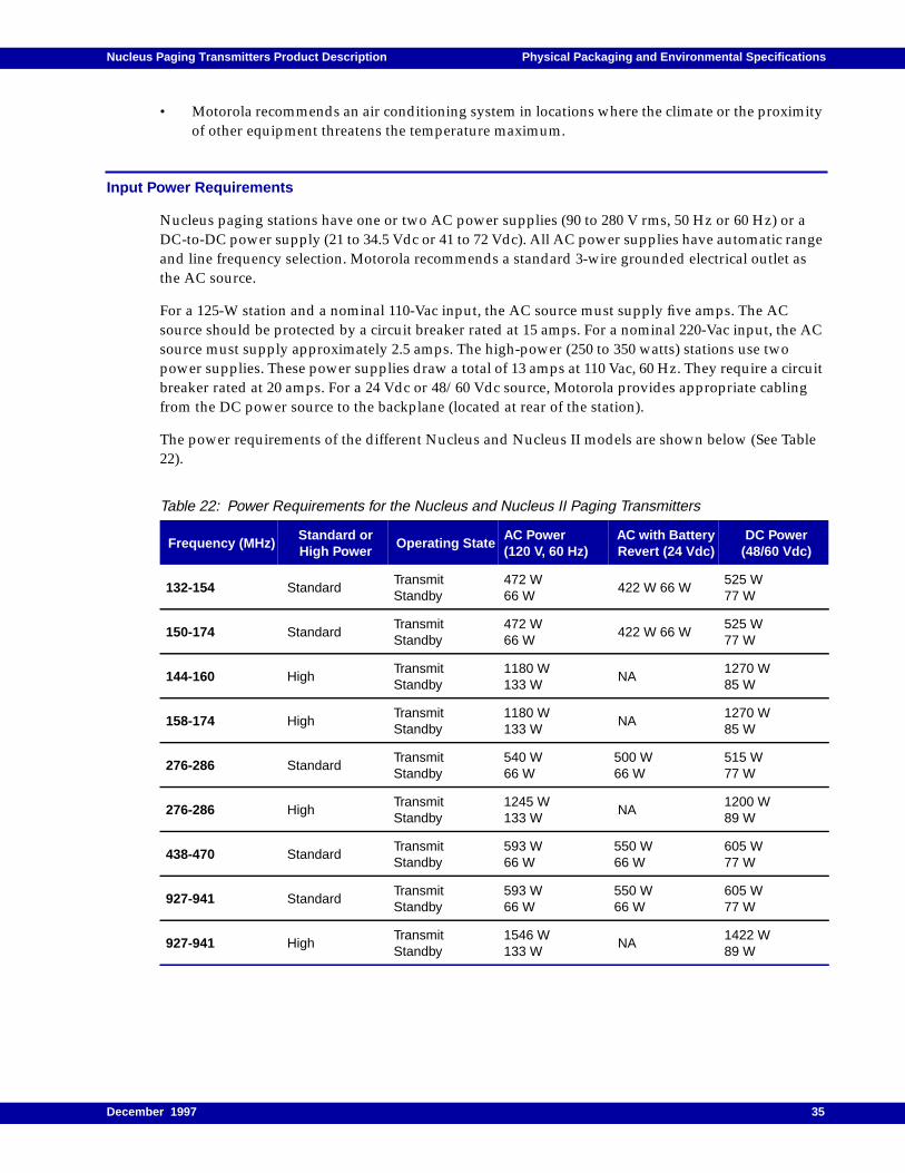
Input Power Requirements
Nucleus paging stations have one or two AC power supplies (90 to 280 V rms, 50 Hz or 60 Hz) or aDC-to-DC power supply (21 to 34.5 Vdc or 41 to 72 Vdc). All AC power supplies have automatic rangeand line frequency selection. Motorola recommends a standard 3-wire grounded electrical outlet asthe AC source.
For a 125-W station and a nominal 110-Vac input, the AC source must supply five amps. The ACsource should be protected by a circuit breaker rated at 15 amps. For a nominal 220-Vac input, the ACsource must supply approximately 2.5 amps. The high-power (250 to 350 watts) stations use twopower supplies. These power supplies draw a total of 13 amps at 110 Vac, 60 Hz. They require a circuitbreaker rated at 20 amps. For a 24 Vdc or 48/60 Vdc source, Motorola provides appropriate cablingfrom the DC power source to the backplane (located at rear of the station).
The power requirements of the different Nucleus and Nucleus II models are shown below (See Table22).
Table 22: Power Requirements for the Nucleus and Nucleus II Paging Transmitters
Frequency (MHz)Standard orHigh Power
Operating StateAC Power(120 V, 60 Hz)
AC with BatteryRevert (24 Vdc)
DC Power(48/60 Vdc)
132-154 StandardTransmitStandby
472 W66 W
422 W 66 W525 W77 W
150-174 StandardTransmitStandby
472 W66 W
422 W 66 W525 W77 W
144-160 HighTransmitStandby
1180 W133 W
NA1270 W85 W
158-174 HighTransmitStandby
1180 W133 W
NA1270 W85 W
276-286 StandardTransmitStandby
540 W66 W
500 W66 W
515 W77 W
276-286 HighTransmitStandby
1245 W133 W
NA1200 W89 W
438-470 StandardTransmitStandby
593 W66 W
550 W66 W
605 W77 W
927-941 StandardTransmitStandby
593 W66 W
550 W66 W
605 W77 W
927-941 HighTransmitStandby
1546 W133 W
NA1422 W89 W
December 1997 35