Nuclear Waste Glasses: Continuous Melting and Bulk .../67531/metadc...NuclearWaste Glasses:...
10
ORP-37171-FP Revision 0 Nuclear Waste Glasses: Continuous Melting and Bulk Vitrification Prepared for the U.S. Department of Energy Assistant Secretary for Environmental Management P.O. Box 450 Rich/and, Washington 99352 Approved for Public Release; Ful1her Dissemination Unlimited
Transcript of Nuclear Waste Glasses: Continuous Melting and Bulk .../67531/metadc...NuclearWaste Glasses:...

ORP-37171-FPRevision 0
Nuclear Waste Glasses:Continuous Melting andBulk Vitrification
Prepared for the U.S. Department of EnergyAssistant Secretary for Environmental Management
P.O. Box 450Rich/and, Washington 99352
Approved for Public Release;Ful1herDissemination Unlimited

ORP-37171-FPRevision 0
Nuclear Waste Glasses: ContinuousMelting and Bulk Vitrification
P. R. HrmaPacific Northwest National Laboratory
A. A. KrugerDepartment of Energy - Office of River Protection
Date Published
March 2008
To Be Presented at9th ESG Conference with the Annual Meeting of the ICG
International Commission on Glass (ICGI ~ European Society of Glass (ESG)Trenein, Czech Republic
June 22-26, 2008
Published InProceedings of 9th ESG Conference
Prepared for the U.S. Department of EnergyAssistant Secretary for Environmental Management
P.O. Box 450Rich/and. Washington 99352
Copyright LicenseBy acceptance of this article, the publisher and/or recipient acknowledges the U.S. Government's right to retaina nonexclusive, royalty-free license in and to any copyright covering this paper.
--I.j)-,~Mease Approval
Approved for Public Release;Further Dissemination Unfimited

LEGAl DISCLAIMERThis report was prepared as an account of work sponsored byan agency of the United Slates Govemment. Neither the UnitedStates Government nor any agency thereof. nor any of theiremployees, nor any of their contractors. subcontractors or theiremployees, makes any warranty, express or implied. orassumes any legal liability or responsibility for the accuracy,completeness, or any third party's use or the results of such useof any Information, apparatus, product, or process disclosed, orrepresents that Its use would not infringe privately owned rights.Reference herein to any specific commercial product, process,or service by trade name, trademark, manufacturer, orotherwise, does not necessarily constitute or imply itsendorsement, recommendation, or favoring by the UnitedStates Government or any agency thereof or its contractors orsubcontractors. The views and opinions of authors expressedherein do not necessarily state or reflect those of the UniteclStates Government or any agency thereof.
ThiS report has been reproduced from the best available copy.Available in paper copy.
PrInted in the United States of America
ORP-37171-FPRevision 0

Nuclear Waste Glasses:Continuous Melting and Bulk Vitrification
P. Hrma1, a and A. A. Kruger' b
1Pacific Northwest National Laboratory
P.O. Box 999, MSIN K6-24, Richland, Washington 99354, USA
2 US Department of Energy
Office of River Protection
P.O. Box 450, MSIN H6-60, Richland, Washington 99352, USA
·[email protected]; [email protected]
Keywords: waste glasses, continuous melting, bulk vitrification
Abstract. This contribution addresses various aspects of nuclear waste vitrification. Nuclear wasteshave a variety of components and composition ranges. For each waste composition, the glass mustbe formulated to possess acceptable processing and product behavior defmed in terms of physicaland chemical properties that guarantee the glass can be easily made and resist environmentaldegradation. Glass formulation is facilitated by developing property-composition models, and thestrategy of model development and application is reviewed. However, the large variability of wastecompositions presents numerous additional challenges: insoluble solids and molten salts maysegregate; foam may hinder heat transfer and slow down the process; molten salts may accumulatein container refractory walls; the glass on cooling may precipitate crystalIine phases. Theseproblems need targeted exploratory research. Examples of specific problems and their possiblesolutions are discussed.
Introduction
The majority of nuclear waste in the world originates from the nuclear fuel cycle and nuclearweapons reprocessing [1]. At least 108 sites containing radioactive waste exist in the United States.Perhaps the most prominent among them is the Hanford Site in the State of Washington [2], where177 underground radioactive waste tanks contain roughly 200,000 m' of radioactive liquid andsludge from plutonium production from 1944 to 1987.
Hanford Site waste will be pretreated and separated into high-level waste (HLW) and lowactivity waste (LAW) fractions. Both HLW and LAW will be vitrified in continuous melters, and asubstantial portion of the LAW will be partitioned to a supplemental LAW treatment. To makenuclear-waste glass, the waste streams from a pretreatment facility, in the form of HLW slurries orLAW solutions, are mixed with glass-forming and modifying additives in the HLW or LAWvitrification facilities, respectively. In both facilities, the resulting melter feeds are charged intoelectrically heated continuous melters from which the molten glass is poured into staiuless-steelcanisters for disposal in the Yucca Mountain repository or stainless-steel containers for disposal inthe Hanford Integrated Disposal Facility.
This paper briefly reviews the glass-formulation method for making glasses that easily melt andmeet the quality required for disposal. Also discussed are property-composition relationships,processing problems, and glass-durability issues.
Glass Formulation
To make certain waste glass is easily processable and has a quality conforming to the regulatoryrequirements for disposal, the glass must be properly formulated for any waste composition (within

the defmed range) that may be delivered from the waste pretreatment facility. These projected wastestreams will substantially vary, both in the number and concentration ranges ofmajor components.
Melt processability and product quality are defmed in terms of glass properties. Glasses areformulated using mathematical relationships, also called models, that link key properties to glasscomposition. The models are expressed in terms of response functions, usually polynomials relatingproperties to mass or mole fractions of components; the numerical coefficients are determined byapplying regression analysis to experimental data.
For continuous melters, glass properties that must be controlled to allow easy processing are themelt viscosity, electrical conductivity, and liquidus temperature. This is because the processingtemperature in waste glass melters cannot exceed 1200°C; above this temperature, the Inconel®electrodes (a material that can withstand waste-melt corrosiveness) lose their mechanical strength.
The product quality of waste glasses is defined by means of outcomes of various standardizedtests, such as the product consistency test [3], vapor hydration test [4], and toxicity characteristicleaching procedure [5]. The quality requirements are more restrictive for LAW glasses becausethese glasses will be less protected in the disposal facilities than HLW glasses in the repository.Economic criteria (glass volume and process rate) are also important and must be considered.
For most composition regions of waste glasses, ftrst-order polynomials are sufficiently
representative [6]; i.e., P =f(I.:/:x;) , where P is the glass property, f is the response function
(e.g., exp), Xi is the i-th component fraction (mass or mole) in glass, and Pi is i-th componentproperty coefficient (partial speciftc or molar property).
As glass components originate from waste, additives, or both, they are subjected to massbalances in the form Xi = WiW + ai(l - W), where Wi is the i-th component fraction in the nonvolatile portion of waste, ai the i-th component fraction in non-volatile portion of additives, andW the waste loading (the fraction of glass that origiuated in the waste). Mathematically speaking,the task of glass formulation is to determine the optimum value of Wand optimized values of ajS
that yield glass with acceptable properties for a given set of Wi values.Because models are subjected to uncertainties, experimental conftrmation is necessary before a
glass is subjected to large-scale testing and production. Thus, glass formulation proceeds in thefollowing steps:I) For the given waste, determine a glass composition with optimized properties using property-
composition relationships.2) Prepare a simulant of the glass using nonradioactive surrogates and measure its key properties.3) Compare measured and calculated properties and adjust the formulation ifnecessary.4) Prepare the fmal simulant glass and measure its key properties.5) Prepare glass from the actual waste and measure its key properties.
Processing Problems
Not all processing problems can be avoided by formulating glasses with desirable properties.Unlike in the processing of commercial glasses, the feed composition of waste glasses is onlypartially controlled. This can lead to various problems described in this section.
As shown schematically in Fig. I, the melter feed (waste plus additives that may be premeltedinto a frit) is charged into the continuous melter in the form ofa water slurry that dries in the melterand forms a cold cap on the pool of molten glass (similar to batch pile or batch blanket ofcommercial-glass melters).
As presented in Fig. 2, various intermediate solids can form within the cold cap [7]. Thesesolids can be transferred to the melter bottom by descending convection currents where they cansettle (Fig. 3) and eventually block the melter outlet. If the bottom sludge is electrically conducting,it can distort the electric fteld in the melter.
Molten ionic salts (predominantly sulfates) tend to segregate during the melting process andaccumulate on the melt surface, causing refractory corrosion. As presented in Fig. 4, undissolvedsulfate is taken to the melt surface inside gas bubbles [8].

Also, foaming is often a serious problem. Melting reactions produce a large volume of gas ofwhich a small fraction is trapped in the glass-forming melt and later released. More troublesome isthe foam from bubbles released from molten glass from multivalent oxides such as FeOx. This foaminsulates the cold cap, slowing the transfer of heat needed for melting [9].
fe<4I"_'!Ql",1<I
"'00"" 700 800 900
Temperature (0C)
Fig. 2. Intermediate crystalline phases thatform in a Savannah River waste glass [7].
Fig. I. Schematic of continuouswaste-glass melter.
Fig. 3. Micrograph of a melter-bottomsludge (spinel and silver) [10].
Fig. 4. Scanning electron Microscopy (SEM)image of sulfate bubble in an LAW glass [8].
Bulk vitrification has been recently designed as a supplemental process for vitrifying LAW.Dry feed is charged into a large (7.3x2.3x2.3 m) metallic box lined with layers of refractory andinsulating materials and electrically heated with two graphite electrodes. The box is then sealed andused as a waste package for disposal.
Bulk vitrification is facing similar problems as those in continuous melting. Molten saltssegregated on the melt surface may contain technetium (Tc) that is present in LAW in minuteconcentrations. Though precipitation and settling of the crystalline phase is not a problem, liquidmetals can precipitate and accumulate at the container bottom. Metals can contain metallic Tc thatcan be easily released in a humid environment. Finally, releasable Tc can accumulate in the glasscontact refractory walls that are made from a relatively inexpensive castable refractory material.Molten salts (mainly nitrates) from LAW can migrate into these walls, driven by capillarity.
While methods for avoiding salt accumulation on the melt surface are currently beinginvestigated, the other problems have been solved. Metal precipitation can be eliminated by usinglow-iron additives. The migration of salts into the walls was reduced to an acceptable level byincreasing the specific surface area of the feed additives (using fine silica) and by celluloseadditions that destroy a portion of nitrates at temperatures at which the salts are relatively immobile[I I].

Process Rate
The rate of melting is an important productivity issue, especially for continuous melters.The melting rate is controlled jointly by the heat-transfer rate and the rate of feed-to-glassconversion [9]. This can be expressed as
2[( 2)"2 ]N= Nc 1+ 4N,H -12NH Nc
where N is the rate of melting (mass per time and area), Nc is the conversion-controlled rate ofmelting, and NH is the heat-transfer-controlled rate ofmelting. These rates are defmed as
and
where I.e and AH are effective heat conductivities of the cold cap and molten glass, Tc and TM arethe temperatures of the cold cap and the bulk melt, respectively, I) is the thermal-boundary-layerthickness, k is the conversion-rate coefficient, p is the feed density, and Q is the conversion heat(the energy needed to turn slurry feed under ambient conditions to 1 kg of glass). The thickness ofthe thermal boundary layer is defmed as I) = (TM - T.)/(I)TIl)y)y=O, where y is the vertical distancefrom the cold-eap-melt interface and Tr is the temperature of the cold-cap-melt interface.
Both the heat transfer and the conversion process are upset if fluxes (that are present in the formof low-viscosity molten ionic salts, also called the primary melt, existing at temperatures at whichthe glass-fonning melt has not yet developed) migrate out of the cold cap. This leads to cold-capfreezing and inability to reach a steady state in the melter.
An important factor affecting the heat-transfer rate is the melt viscosity, which influences thevelocity of natural convection in the melter and the extent of bubble/foam accumulation under thecold cap [I2]. Because viscosity depends on glass composition, glass formulation is of a crucialimportance for melter operation. For fast melting, the viscosity near the cold-cap bottom surfaceshould be as low as possible.
Heat can be transferred from the hot melt to the cold cap faster by increasing the melttemperature and by bubbling. A higher melt temperature increases the temperature gradient in themelt under the cold cap, thus increasing the density gradient, which is the driving force for meltcirculation. Bubbling further enhances melt circulation, removes foam accumulated under the coldcap, and even breaks through the cold cap, exposing a larger interface area to melting. Increasedmelt circulation (by increased temperature, decreased viscosity, and bubbling) suppresses thethermal boundary layer under the cold cap, increasing the heat flux to the cold cap.
Note that Eq. 2 grossly oversimplifies the conversion process by reducing a rather complex setof parallel and sequential reactions and transitions with one rate coefficient, k. In reality, theconversion process proceeds in several stages. As the feed temperature increases, the ionic saltsbegin to melt, forming the primary melt. The reactive components of the primary melt, such ascarbonates and nitrates, react with silica, creating the glass-forming melt while leaving behind lessreactive sodium sulfate that only gradually dissolves in the glass-forming melt. Once the glassforming melt connects into a continuous body, the residues of molten salts and oxidation-reductionreactions generate gases that are trapped inside the melt in the form of bubbles. The resulting
(1)
(2)
(3)
primary foam increases the melt volume several times [12] and collapses as soon as the meltviscosity decreases below a certain level. These stages are common to waste and commercial feedsand hatches.
The complexity of the feed-to-glass conversion process indicates that its rate can be influencedby many internal parameters. Probably most prominent among them is the content of reductants,such as sugar or cellulose, in the feed. Reductants react with oxyionic salts, especially nitrates andnitrites, and with high-valence oxides, such as Fez03 and Mn20 3. These reactions are exothermic:They internally supply heat to the cold cap independent of heat transfer from external sources. Also,reducing the content of ionic salts in the cold cap decreases the potential for flux separation thatleads to cold-eap freezing. The importance of reductants for bulk vitrification has been mentionedabove.
The impact of the primary foam on the rate of melting is not well understood. It is not clearwhether the main effect of primary foam is insulating the cold cap or whether the growing bubbleshelp to homogenize the melt, thus helping dissolve the solid particles.
Product Quality Issues: Loug-Term Corrosion
As stated above, glass acceptability for disposal is defmed by responses to standard corrosion tests.Glass corrosion is a function of thermodynamic state variables (temperature and composition) aswell as the kinetics of various individual reactions that participate in the corrosion process. It is notwell understood at present how the responses of glass to standard tests relate to long-term corrosionbehavior, especially when considering the poor predictability of the environmental conditions overthe hundred-thousand years that the radioactivity needs to decay.
Under laboratory conditions in a closed system, glass corrosion proceeds in four stages: initialstage, solution-satoration stage, traosition stage (a catastrophic event), and fmal stage.The traosition stage occurs when mineral species suddeuly precipitate from the oversatoratedsolution. In the fmal stage, glass dissolution is controlled by the aqueous reactions. It is not clearwhether these two fmal stages can occur in the open system.
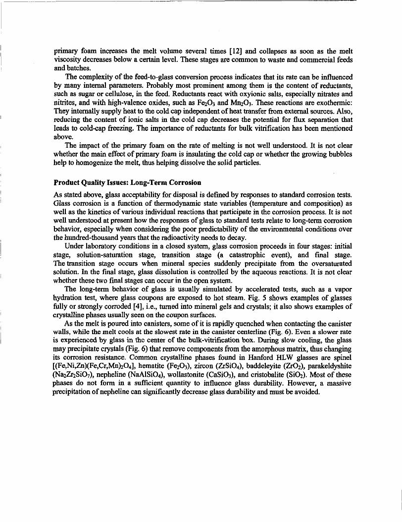
The long-term behavior of glass is usually simulated by accelerated tests, such as a vaporhydration test, where glass coupons are exposed to hot steam. Fig. 5 shows examples of glassesfully or strongly corroded [4], i.e., turned into mineral gels and crystals; it also shows examples ofcrystalline phases usually seen on the coupon surfaces.
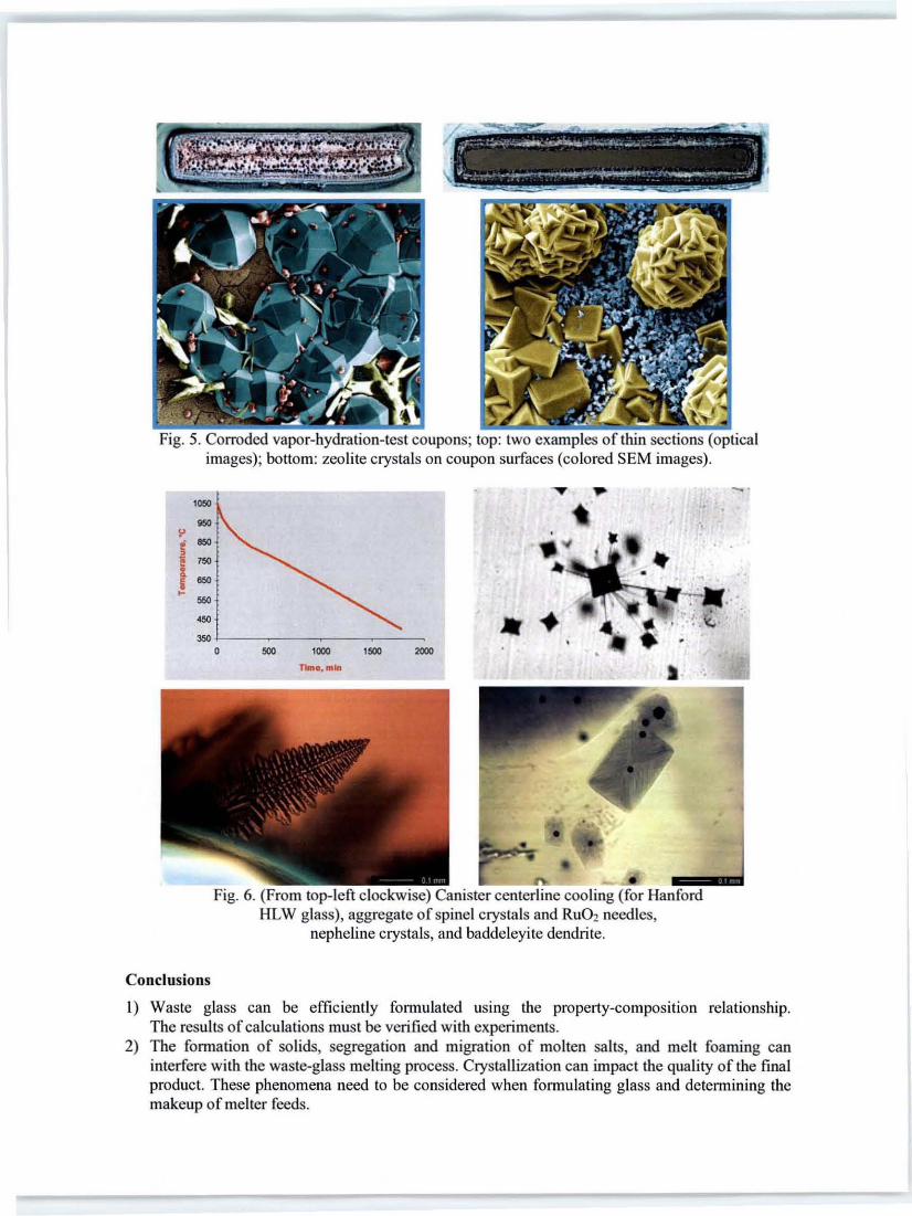
As the melt is poured into canisters, some of it is rapidly quenched when contacting the canisterwalls, while the melt cools at the slowest rate in the canister centerline (Fig. 6). Even a slower rateis experienced by glass in the center of the bulk-vitrification box. During slow cooling, the glassmay precipitate crystals (Fig. 6) that remove components from the amorphous matrix, thus changingits corrosion resistance. Common crystalline phases found in Hanford HLW glasses are spinel[(Fe,Ni,Zn)(Fe,Cr,Mn)204], hematite (Fez03), zircon (ZrSi04), baddeleyite (Zr02), parakeldyshite(Na2Zr2Si07), nepheline (NaAlSi04), wollastonite (CaSi03), and cristohalite (Si02). Most of thesephases do not form in a sufficient quantity to influence glass durability. However, a massiveprecipitation ofnepheline can significantly decrease glass durability and must be avoided.
· - -- -- ----- -=--,. :..~ ....,.... ~....,.~IC;,. 0_ ( .. __ . ~~.~ .. ~
"
J._ ••_.__ ••••_~.. ~...--..' ~ _.. __ ,
---~~ .. ~~.. _.~
Fig. 5. Corroded vapor-hydration-test coupons; top: two examples of thin sections (opticalimages); bottom: zeolite crystals on coupon surfaces (colored SEM images).
'000
"
2000'SOD'000Time, min
SOD
Fig. 6. (From top-left clockwise) Canister centerline cooling (for HanfordHLW glass), aggregate of spinel crystals and RU02 needles,
nepheline crystals, and baddeleyi te dendrite.
Conclusions
I) Waste glass can be efficiently formulated using the property-compositIOn relationship.The results of calculations must be verified with experiments.
2) The formation of solids, segregation and migration of molten salts, and melt foaming caninterfere with the waste-glass melting process. Crystallization can impact the quality of the fmalproduct. These phenomena need to be considered when formulating glass and determining themakeup of melter feeds.

3) Predicting the fate of glass over hundreds of thousands of years in a geologic repository basedon various short-term corrosion tests remains a challenge. In a closed system, glass corrosionproceeds through fOUf stages of which the last two (transition and final) are determined bymineral precipitation from the aqueous medium.
4) Bulk vitrification to accelerate LAW immobilization is still being evaluated. The major obstacleto its implementation on a large scale, the migration of waste species into the refractory lining,has been overcome by using fine-grain additives and adding cellulose to the melter feed.
References
[I] Information on http://en.wikipedia.org/wikilNuclear_waste.
[2] Information on http://en.wikipedia.org/wiki/Hanford_Site.
[3] Standard Test Methods for Determining Chemical Durability of Nuclear, Hazardous, andMixed Waste Glasses: The Product Consistency Test (PCT), C 1285-97. In: 1998 Annual Bookof ASTM Standards, Vol. 12.01 (American Society for Testing and Materials, WestConshohocken, Pennsylvania, 1998).
[4] A. Jiricka, J.D. Vienna, P. Hnna and D.M. Strachan: J. Non-Cryst. Solids, Vol. 292 (2001),pp.25-43.
[5] Test Methods for Evaluation of Solid Waste Physical/Chemical Methods, SW-846, 3rd. Ed.,(U.S. Environmental Protection Agency, Washington, D.C., 1997).
[6] P. Hrrna, G.F. Piepel, MJ. Schweiger, D.E. Smith, D-S. J(jm, P.E. Redgate, J.D. Vienna, C.A.LoPresti, D.B. Simpson, O.K. Peeler, and M.H. Langowski, Property/CompositionRelationships for Hanford High-Level Waste Glasses Melting at 1150°C, PNI..-10359, Vol. 1and 2 (Pacific Northwest Laboratory, Richland, Washington, 1994).
P. Hrrna, J.V. Crum, OJ. Bates, P.R. Bredt, L.R. Greenwood and H.D. Smith: J. Nucl. Mater.,Vol. 345 (2005), pp. 19-30.
P. Hrma, J.V. Crum, P.R. Bredt, L.R. Greenwood, B.W. Arey and H.D. Smith: J. Nucl. Mater.,Vol. 345 (2005), pp. 31--40.
[7] P. Hrrna, J. Matya~ and D.-S. J(jm, The Chemislly and Physics of Melter Cold Cap, in: rjhBienniallntemational Conference on Nuclear And Hazardous Waste Management, Spectrum'02, American Nuclear Society, CD-ROM (2002).
[8] P. Hrrna, J.D. Vienna and J.S. Ricklefs: Mat. Res. Soc. Proc., Vol. 143 (2003), pp. 159-167.
P. Hrrna, J.D. Vienna, W.C. Buchmiller and J.S. Ricklefs: Ceramic Trans., Vol. 155 (2004),pp.93-100.
[9] P. Hrma: Glastech. Ber., Vol. 63K (1990), pp. 360--369.
[I0]M. Jiricka and P. Hrrna: Ceramic-Silikaty, Vol. 46(1) (2002), pp. 1-7.
[II] P. Hrma, L.M. Bagaasen, MJ. Schweiger, M.B. Evans, B.T. Smith, B.M. Arrigoni, D.-S. J(jm,c.P. Rodriguez, S.T. Yokuda, J. Matyas, W.C. Buchmiller, A.B. Gallegos and A. Fluegel: BulkVitrification Performance Enhancement: Refractory Lining Protection Against Molten SaltPenetration (Pacific Northwest National Laboratory, RicWand, Washington, 2007).
[12] D.-S. Kim and P. Hrrna: Ceram. Bull., Vol. 69(6) (1990), pp. 1039-1043.
D.-S. J(jm and P. Hrrna: J. Am. Ceram. Soc., Vol. 74(3) (1991), pp 551-555.