Nuclear material Processing at the Savannah River...
24
by T. F. Severynse Westinghouse Savannah River Compiany Savannah River Site Aiken, South Carolina 29808 I f WSRC-MS-98-00515 Nuclear material Processing at the Savannah River Site DOE Contract No. DE-AC09-96SR18500 This paper was prepared in connection with work done under the above contract number with the U. S. Department of Energy. By acceptance of this paper, the publisher and/or recipient acknowledges the U. S. Government's right to retain a nonexclusive, royalty-free license in and to any copyright covering this paper, along with the right to reproduce and to authorizls others to reproduce all or part of the copyrighted paper.
Transcript of Nuclear material Processing at the Savannah River...
by T. F. Severynse Westinghouse Savannah River Compiany Savannah River Site Aiken, South Carolina 29808
I f
WSRC-MS-98-00515
Nuclear material Processing at the Savannah River Site
DOE Contract No. DE-AC09-96SR18500
This paper was prepared in connection with work done under the above contract number with the U. S. Department of Energy. By acceptance of this paper, the publisher and/or recipient acknowledges the U. S. Government's right to retain a nonexclusive, royalty-free license in and to any copyright covering this paper, along with the right to reproduce and to authorizls others to reproduce all or part of the copyrighted paper.

DISCLAIMER
This report was prepared as an ilCCOUnt of work sponsored by an agency of the United States Government. Neither the United States Government nor any agency thereof, nor any of their employees, makes any warranty, express or implied, or assumes any legal liability or responsibility for the accuracy, completeness, or usefulness of any information, apparatus, product, or process disclosed, 01- represents that its use would not infringe privately owned rights. Reference herein to any specific commercial product, process, or service by trade name, trademark, manufacturer, or otherwise does not necessarily constitute or imply its endorsement, recommendation, or favoring by the United States Government or any agency thereof. The views and opinions of authors expressed herein do not necessarily state or reflect those of the United States Government or any agency thereof.
This report has been reproduced directly from the best available copy.
Available to DOE and DOE contractors from the Office of Scientific and Technical Information, P. 0. Box 62, Oak Ridge, TN 37831; prices available from (423) 576-8401.
Available to the public from the National Technical Information Service, U. S . Department of Commerce, 5285 Port Royal Road, Springfield, VA 22161.

DISCLAIMER
Portions of thi:s document may be illegibie electronic image products. Images are produced fromi the best available original document.

NUCLEAR MATERIAL PROCESSING
AT THE
SAVANNAH RIVER SITE
- TABLE OF CONTENTS
1.0 Executive Summairy
2.0 Processing History
3.0 SRS Processing Facilities
4.0
5.0 Facility Descriptions
6.0
Current Missions and Facility Status
Aqueous Processing - Improved Capability

1.0 Executive Summary
Plutonium production for national’defense began at Savannah River in the mid- 1950s, following construction of production reactors and separations facilities. Following the successful completion of its production mission, the site’s nuclear material processing facilities continue to operate to perform stabilization of excess materials and potentially support the disposition of these materials. A number of restoration and productivity improvement projects implemmted in the 1 980s’ totaling nearly a billion dollars, have resulted in these facilities representing the most modern and only remaining operating large-scale processing facilities in the DOE Complex. Together with the site’s extensive nuclear infrastructure, and integrated waste management system, SRS is the only DOE site with the capability and mission of ongoing processing operations.
2.0 Plutonium Processing History
Savannah River was constructe:d in the early 1950s to provide special nuclear materials, primarily tritium and plutoniuni-239, for national defense. Five heavy water-moderated production reactors and two remotely operated processing facilities were commissioned over a five-year period.
Plutonium was produced by thc: irradiation of natural uranium target elements, followed by dissolution of the targets in nitric acid, and plutonium separation and purification using the PUREX process. This process uses a series of countercurrent solvent extraction stages to separate uranium and plutonium from fission products, and to effectively partition the uranium and the plutonium. The startup of F Canyon in November, 1954 was the first implementation of PUREX on a production scale. In comparison to the existing process at Hanford, PU REX provided greatly increased throughput, and significantly less waste volume due to the recovery of uranium.
The purified uranium was transferred outside the canyon building for concentration and thermal decomposition to produce uranium oxide. Dilute plutonium product solution from the canyons was transferred to finishing lines located within the same structure. These process lines (F B-Line and H B-Line) consisted of a series of gloveboxes with equipment to concentrate, precipitate, and reduce the plutonium to form a metal button for shipment offsite. The total amount of weapons-grade plutonium produced at Savannah River is approximately forty metric tons.
H Canyon began operation in July, 1955 to recover plutonium from irradiated natural uranium targets. In 1968, reactor operations were modified to allow use of enriched uranium fuel to produce a greater variety of products. Plutonium was then produced from irradiation of depleted uranium targets. The F Canyon and F B-Line process equipment were modified to increase throughput, and H Canyon was converted for recovery of the enriched uranium “driver” assemblies and neptunium, a byproduct of the production process. HB-Line produced neptunium oxide, and later plutonium-238 oxide for space missions. The plutonium-238 oxide was shipped onsite to the Plutonium Fuel Form facility to produce encapsulated pellets for radioisotopic thermoelectric generators used in NASA missions. This facility also housed a neptunium process line for fabrication of billets, which were extruded into tubes, and charged to the site reactors to produce plutonium-238.

2.0 Plutonium Processing History (Continued)
In the early 1980s, an increased demand for plutonium inspired a series of new initiatives for restoration of existing production facilities, and construction of new facilities. A new H B-Line facility was commissioned to modernize the operation and provide enhanced throughput of neptunium oxide, plutonium-238 oxide, and also plutonium-239 oxide. The Plutonium Storage Facility (PSF) and New Special Recovery (NSR) facility were constructed to provide capability for recovery of plutonium from pits and a variety of scrap materials throughput the complex. Although construction and pre-operational testing of NSR and PSF was completed in 1991, startup was cancelled just prior to the commencement of hot operations due to the reduced demand for weapons materials of all types.
3.0 SRS Processing Facilities
The SRS processing facilities are currently operating to stabilize solutions, residues, and spent fuels. Both F and H area facilities are involved in the program to stabilize legacy materials both from the SRS production cycle and from various other sites in the Complex. While some materials can achieve a safe storage condition (per DOE Standard 30 13) by heat treatment or repackaging, the majority of this program involves acid dissolution, solvent extraction for impurity removal, and outpackaging as a stabilized solid. F Area facilities (F Canyon and FB Line) are currently configured to produce stabilized plutonium in the metal (button) form. Plutonium stabilized in H Area will be produced as an oxalate-precipil ation derived oxide. All stabilized plutonium will be packaged to the DOE 301 3 standard and placed in safe storage in the new Actinide Packaging and Storage Facility awaiting disposition.
3.1 H-Canyon
H-Canyon is a large, heavily shielded concrete structure that provides remote handling and processing of spent aluminum clad fuels for recovery of enriched uranium from production and research reactors. Large (up to 5000 gallons) stainless steel vessels are used to maintain safe concentration of fissile materials during dissolution of the fuel and purification of the uranium. Historically, the annual throughput of HEU is in the range of five to ten metric tons.
Nitric acid is used to dissolve the fuel rods, producing a solution of aluminum, uranium, neptunium, plutonium, and fiss. on products. Three cycles of solvent extraction provide rejection of fission products and plutonium to aqueous waste, as well as separation and purification of the uranium and neptunium. Piping configuration, solution transfer, process sampling and instrumentation are implemented remotely, using overhead bridge cranes and embedded piping from equipment corridors adjacent to the process cells. The uranium solution, previously transported offsite for recycle in the DOE fuel cycle, is currently being stored for future use as commercial nuclear power reactor fuel. Neptunium solution is transferred to H B-Line for conversion to oxide for storage.

3.1 H-Canyon (Continued)
The modified PUREX process f lowsheet in use in H-Canyon provides for recovery of neptunium produced during irradiation of the enriched uranium fuel rods in the reactor. Historically, the flexibility of the both the process flowsheet and the equipment arrangement have made recovery of other special isotopes, including plutonium-239, plutonium-242, and uranium-23 3 technically and economically possible. Plutonium-238 recovery, using an ion exchange process, has also been accomplished using remotely operated canyon facilities.
3.2 HB-Line
This facility consists of three connected lines called “phases” located on top of H Canyon with various services and process operations interconnects. Phase I is a scrap dissolution line, Phase 11, a neptuniudplutonium purification and oxide conversion, and Phase I11 for plutonium-238 oxide production. Plutonium metal or oxide can be charged to the Phase I dissolvers, and transferrzd to Phase I1 for processing through anion exchange for contaminant removal and concentration. The purified solution is adjusted and fed to a two-stage precipitator with oxalic acid as the precipitant. The plutonium oxalate cake is filtered, washed, and transferred to a drying station. The dried cake is moved to a roasting furnace for conversion to oxide. The design throughput for the process is approximately one metric ton per year. A11 operations are included in the existing facility Authorization Basis. Phase I operations are currently in progress; Phase I1 startup preparations are in progress, with startup authorization scheduled for late fiscal year 2000. Phase III was last operated in 1997 but has no current mission.
3.3 FCanyon
The F-Canyon building is essentially identical to that of H-Canyon. Using the original PUREX process, depleted uranium targets are dissolved in a two-stage process to produce a solution of uranium, plutonium, and fission products. Three cycles of solvent extraction produce product streams of uranium and plutonium, which are converted to oxide and metal, respectively. With respect to the H-Canyon enriched uranium process, the F-Canyon process is significantly larger volumetrically, processing metric ton quantities of uranium per day. l>rocess and equipment modifications completed in past years have allowed recovery of many specialty isotopes, including americium and curium. Currently, flowsheets have been implemented to allow dissolution and processing of both plutonium metal and plutonium scrap materials remaining from the metal production process.

3.4 FI3-Line
FB Line occupies the upper levels of a portion of F Canyon. Its design function was to convert plutonium nitrate solution after purification by solvent extraction in the canyon, to metal buttons for weapons purposes. The current FB-Line process uses cation exchange to concentrate dilute plutonium nitrate feed, followed by precipitation of plutonium trifluoride using hydrofluoric acid. After conversion by heating to an oxideketrafluoride mixture, metallic calcium is added for the reduction of the plutonium to metal. Cation column raffinale, filtrates, and filter boat flush solution are returned to F- Canyon for recycle or disposal. Purified plutonium oxide has been and can be produced in FB-Line from plutonium feed solution from F-Canyon; however, process modifications would be required.
Oxide production would require the installation of an oxalic acid addition station, filter boat flush solution makeup station, and modifications to the roasting pan dumper station to handle oxide powder. Throughput is estimated to be a maximum of one metric ton per year. Some options are possible to increase oxide production capacity. Although oxide production has been performed previously in FB-Line, it is not part of the current facility Authorization Basis, and would require evaluation and operational readiness review prior to implementation.
3.5 New Special Recovery
The New Special Recovery (NSR) facility was constructed to provide the capability for plutonium scrap recovery, primxily from oxide. In conjunction with the adjacent Plutonium Storage Facility, scrap materials (oxide or metal) were received, oxidized, and charged to a small dissolver loc3ted in a glovebox line. Following dissolution using a mixture of nitric and hydrofluoric acid, plutonium purification was completed using an ion exchange process. The product plutonium solution could then be transferred to the F- Canyon process for blending with other solutions to achieve the desired isotopic mixture. The heavily shielded glovebox lx-ocess contained a high degree of automation to minimize personnel radiation exposure during operations. Production capacity was estimated to be two metric tons of oxide per year.
4.0 Current Missions and Facility Status
The majority of pIutonium processing facilities at Savannah River are currently operating to stabilize legacy materials, specifically:
H Canyon is processing site reactor fuel (HEU). Enriched uranium solution is being stored onsite for isotopic blending to produce suitable feed for use as commercial reactor fuel. TVA and DOE: are negotiating with commercial fuel fabricators to establish an extended program of HEU conversion to commercial fuel. NEPA activities are in progress which are likely to result in additional fuel processing missions.
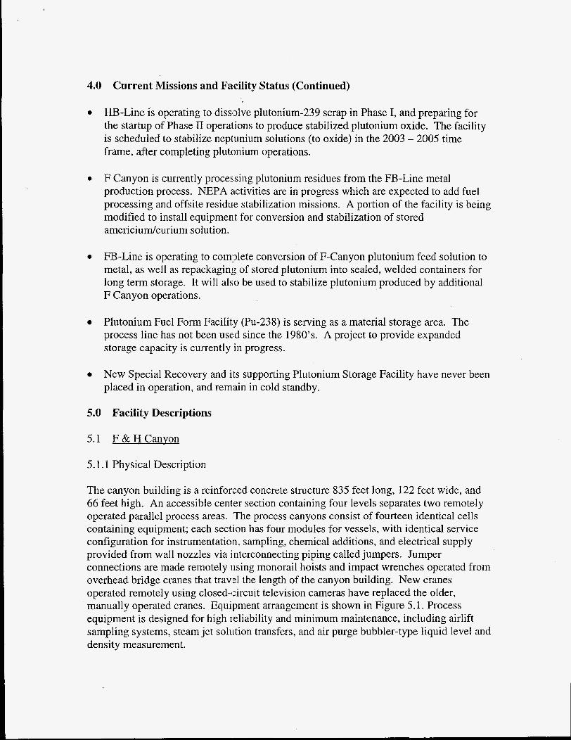
4.0 Current Missions and Facility Status (Continued)
HB-Line is operating to dissolve plutonium-239 scrap in Phase I, and preparing for the startup of Phase II operations to produce stabilized plutonium oxide. The facility is scheduled to stabilize neptunium solutions (to oxide) in the 2003 - 2005 time frame, after completing plutonium operations.
F Canyon is currently processing plutonium residues from the FB-Line metal production process. NEPA activities are in progress which are expected to add fuel processing and offsite residue stabilization missions. A portion of the facility is being modified to install equipment for conversion and stabilization of stored americiudcurium solution.
FB-Line is operating to com:?lete conversion of F-Canyon plutonium feed solution to metal, as well as repackaging of stored plutonium into sealed, welded containers for long term storage. It will also be used to stabilize plutonium produced by additional F Canyon operations.
Plutonium Fuel Form Facility (Pu-238) is serving as a material storage area. The process line has not been used since the 1980’s. A project to provide expanded storage capacity is currently in progress.
New Special Recovery and its supporting Plutonium Storage Facility have never been placed in operation, and remain in cold standby.
5.0 Facility Descriptions
5.1 F & H Canyon
5.1.1 Physical Description
The canyon building is a reinforced concrete structure 835 feet long, 122 feet wide, and 66 feet high. An accessible center section containing four levels separates two remotely operated parallel process areas. The process canyons consist of fourteen identical cells containing equipment; each section has four modules for vessels, with identical service configuration for instrumentation, sampling, chemical additions, and electrical supply provided from wall nozzles via interconnecting piping called jumpers. Jumper connections are made remotely using monorail hoists and impact wrenches operated from overhead bridge cranes that travlsl the length of the canyon building. New cranes operated remotely using closed-circuit television cameras have replaced the older, manually operated cranes. Equipment arrangement is shown in Figure 5.1. Process equipment is designed for high 1,eliability and minimum maintenance, including airlift sampling systems, steam jet solution transfers, and air purge bubbler-type liquid level and density measurement.

z 0

5.1.1 Physical Description (Continued)
In addition to the process cells, 1 he canyons contain four additional sections for equipment decontamination, storage, and maintenance, as well as a railroad tunnel for transport of fuel and equipment. The center section provides personnel access to control rooms, cold chemical makeup tanks, piping, and service equipment to support building and process needs. The general building arrangement is shown schematically in Figure 5.2.
5.1.2 Process Description
The H Canyon process uses a modified PUREX flowsheet due to the large quantities of enriched uranium handled in process operations. The process is shown schematically in Figure 5.3. Fuel enters the building in heavily shielded casks on railcars that are moved into the railroad tunnel. The overhead crane removes the cask lid, and transports the fuel bundles to the dissolver, which js equipped with an insert to prevent the fuel bundle from shifting as it dissolves. The diss,olver is charged with nitric acid, and heated to boiling, which dissolves the uranium-alu minum alloy fuel, producing a solution of uranium, aluminum, plutonium, neptuniuin, and fission products. This solution is treated with gelatin and centrifuged in a head end step to remove silicon, which interferes with solvent extraction.
Purification and separation of uranium and neptunium are accomplished by three “cycles” of solvent extraction; each cycle performs an alternating sequence of extraction of products into an organic phase, followed by stripping of the products back into an aqueous phase. In the first cyclt:, the uranium and neptunium form a soluble organic compound and the plutonium and fission products are rejected to the waste stream. Partitioning of neptunium from the uranium is accomplished by acidity and valence adjustment; both the uranium and neptunium are processed through an additional cycle of solvent extraction for further decontamination. Both the uranium and neptunium product streams are stored as in liquid form awaiting further disposition.
F Canyon uses the PUFEX floasheet to recover plutonium from depleted uranium slugs or to purify plutonium from other sources. The process is shown schematically in Figure 5.4. The fuel slugs arrive in buckets in heavily shielded cask cars, and are charged to the dissolver for sequential dissolution using sodium hydroxide for aluminum coating removal, followed by nitric acid for plutonium and uranium dissolution. Head end treatment and solvent extraction operations are similar to those in H Canyon. The plutonium is stored for transfer I:O FB-Line, while the uranium is concentrated and transferred to an adjacent facility for thermal decomposition to uranium oxide.


FIGURE 5.3 ODlFlED PUREX
PROCESS FLOW DIA
t

FIGURE 5.4 F CANYON PUREX PROCESS
ESS FLOW
FISSION PRODUCTS
WASTE TANKS TO F B-LINE
OXIDE STORAGE

5.2 HB-Line
5.2.1 Facility Description
The HB-Line facility consists of‘ three phases enclosed in a hardened structure located on the roof of H Canyon. The facility is 230 feet long and 73 feet wide, and contains two levels. The lower level includes; the three process lines, product loading area, and storage vault; the upper level houses ventilation and other service equipment. The process glovebox lines are configured tcl provide an “operating” side and a “maintenance” side, a design philosophy that allows equipment maintenance to be performed without major disruption of normal process oplxations or increased potential for personnel contamination from maintenance activities.
5.2.2 Process Description
Scrap Recovery
The Scrap Recovery Facility (Phase I) is designed to produce nitrate solutions of 2”Pu or 235U/239Pu from scrap material, For purification via anion exchange or solvent extraction. The process flow diagram is shown in Figure 5.5. Scrap is received, and dissolver batches are prepared based on assay. The scrap material is charged to a geometrically favorable dissolver of slab shape, and dissolved in hot nitric acid containing a trace of fluoride ion. Dissolver offgas is vented through a condenser to the vessel vent system. The dissolver solution is filtered and sampled prior to transfer to the H Canyon via a dilution eductor to ensure criticality safety. Duplicate process lines are provided to provide flexibility to handle various materials.
Oxide Facility
The Oxide Facility (Phase 11) ccmverts neptunium nitrate solutions to neptunium oxide powder. The facility also has the capability to process fissile plutonium nitrate solutions for purification, concentration, and conversion to plutonium oxide solutions. The process flow diagram is shown in Figure 5.6.
Neptunium solution is transferred from H Canyon to receipt tanks for feed adjustment. Plutonium solution can be received from H Canyon, or directly from the Scrap Recovery line. After acid and valence adjustment, the solution is fed to an anion exchange column. Column raffinate is transferred LO H Canyon for processing as waste. The neptunium (or plutonium) is then eluted from the column, and adjusted for precipitator feed. The adjusted feed and oxalic acid art? metered simultaneously to a two-stage precipitator. The resultant oxalate precipitate is fj ltered, washed, and transferred to a furnace for calcination to oxide. Filtrates, washes, and filter boat backflush solutions are transferred to H Canyon for disposal, or recycled to the anion column feed tanks for recovery.

FIGURE 5.5 P RECO ILITY s FLOW
Flu-238 or U/Pu FEED
BACKFLUSH SOLUTION
TO H CANYON OR PHASE II

DILUTE Pu or Np FEED
-LIME NEP IDE FACILITY PROCESS FLOW DIAGRAM
t
r
TO CANYON WASTE PROCESSING
1 P REG 0 P n UAUQ w 1
I
5.2.2 Process Description (Continued)
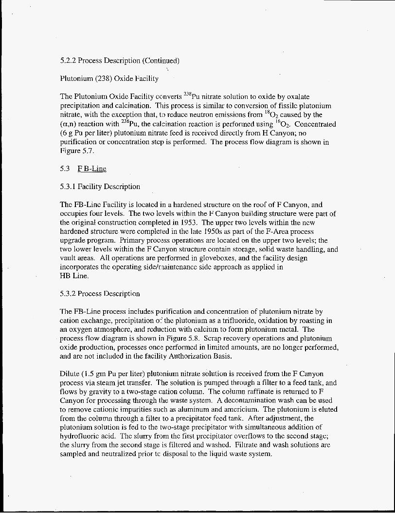
Plutonium (238) Oxide Facility
The Plutonium Oxide Facility converts 238Pu nitrate solution to oxide by oxalate precipitation and calcination. This process is similar to conversion of fissile plutonium nitrate, with the exception that, to reduce neutron emissions from ' '02 caused by the (a,n) reaction with 238Pu, the calcination reaction is performed using 1602. Concentrated (6 g Pu per liter) plutonium nitrate feed is received directly from H Canyon; no purification or concentration step is performed. The process flow diagram is shown in Figure 5.7.
5.3 FB-Line
5.3.1 Facility Description
The FB-Line Facility is located in a hardened structure on the roof of F Canyon, and occupies four levels. The two levels within the F Canyon building structure were part of the original construction completed in 1953. The upper two levels within the new hardened structure were completed in the late 1950s as part of the F-Area process upgrade program. Primary process operations are located on the upper two levels; the two lower levels within the F Canyon structure contain storage, solid waste handling, and vault areas. All operations are performed in gloveboxes, and the facility design incorporates the operating sidehaintenance side approach as applied in HB Line.
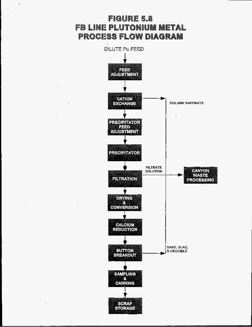
5.3.2 Process Description
The FB-Line process includes piirification and concentration of plutonium nitrate by cation exchange, precipitation of the plutonium as a trifluoride, oxidation by roasting in an oxygen atmosphere, and reduction with calcium to form plutonium metal. The process flow diagram is shown in Figure 5.8. Scrap recovery operations and plutonium oxide production, processes once performed in limited amounts, are no longer performed, and are not included in the facility Authorization Basis.
Dilute (1.5 gm Pu per liter) plutonium nitrate solution is received from the F Canyon process via steam jet transfer. The solution is pumped through a filter to a feed tank, and flows by gravity to a two-stage cation column. The column raffinate is returned to F Canyon for processing through the waste system. A decontamination wash can be used to remove cationic impurities such as aluminum and americium. The plutonium is eluted from the column through a filter to a precipitator feed tank. After adjustment, the plutonium solution is fed to the two-stage precipitator with simultaneous addition of hydroff uoric acid. The slurry from the first precipitator overflows to the second stage; the slurry from the second stage is filtered and washed. Filtrate and wash solutions are sampled and neutralized prior tcl disposal to the liquid waste system.

FIGURE 5.7
PROiCESS FLOW DIAGRA -LINE PLUTONIU OXIDE FACILITY
Pu-238 FEED
I
c
DILUTE Pu FEED
c
FILTRATE
COLUMN RAFFINATE
IAND, SLAG, L CRUCIBLE

5.3.2 Process Description (Continued)
The filter boat containing the plutonium trifluoride precipitate is transferred to an air drying station for moisture removal. The dry cake is dumped to a roasting pan, and charged to a furnace, where it is converted to a 3: 1 mixture of plutonium tetrafluoride and plutonium oxide. The roasted powder from the conversion step is weighed, mixed with calcium metal, and dumped into a prepared reduction vessel consisting of a stainless steel pressure container with a ceramic crucible seated in magnesium oxide sand. The reduction vessel is evacuated and purged with argon to remove oxygen, then heated to initiate calciothennic reaction that produces plutonium metal, calcium fluoride, and calcium oxide. The metallic “button” is cooled, mechanically separated from the crucible, weighed, and sampled prior to canning.
5.4 New Special Recovery
5.4.1 Facility Description
The New Special Recovery (NSR) Facility consists of two levels located on the roof of F Canyon, adjacent to the FB-Line facility. The lower level is a hardened concrete structure containing process and service equipment. The upper level is a soft structure providing space for offices, change rooms, and a cold feed preparation area. The hardened process area consists of 10,500 square feet of floor space, including an adjacent control room that is shared by FB-Line. The facility was constructed during the early 1980s, and meets many of the design criteria of DOE Order 6430.1A. NSR was to be used in conjunction with the adjacent Plutonium Storage Facility (PSF) to receive and process plutonium scrap materials for recycle to F Canyon. Extensive startup preparations were conducted in the late 1980s; however, facility startup was never authorized due to the changing inission requirements for the site. The NSR process included two glovebox lines equipped with dissolvers and anion exchange columns to process and purify plutonium oxide. The plutonium nitrate product solution was transferred to F Canyon for blending.
5.4.2 Process Description
NSR received scrap oxide or metal from its adjoining receivingktorage facility, PSF. A feed preparation glovebox included an oxidation furnace for conversion of metal to oxide, as well as sieves, blender, and scales for screening, mixing, and batching of the oxide powder. Plutonium oxide from the feed preparation glovebox was transferred via overhead conveyor to one of two glovebox lines, and charged to a geometrically favorable slab dissolver. Following dissolution in an agitated mixture of nitric acid and potassium fluoride, the solution was filtered, adjusted, and fed to an anion exchange column. Following a decontamination wash, the plutonium was eluted from the column, sampled, and transferred to F Canyon via an elution eductor to maintain a critically safe concentration of plutonium. Column raffinate and decontamination washes were also transferred to the canyon for processing through the aqueous waste system. The process flow diagram for NSR is shown schematically in Figure 5.9.
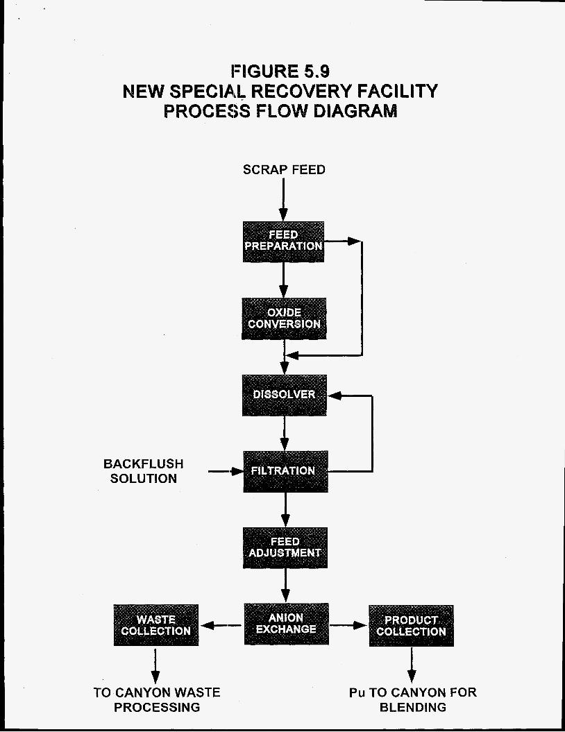
FIGURE 5.9 EW L1, RY LITY
IAG
BACKFLUSH SOLUTION
SCRAP FEED
1
7-
TO CANYON WASTE PROCESSING
Pu TO CANYON FOR BLENDING
6.0 Aqueous Polishing - Enhanced Capability
As discussed in Section 3.0, process operations in existing site facilities can provide limited capability (up to one metric ton per year) for the preparation of purified plutonium oxide. Higher throughput (three to four metric tons per year) can be obtained by implementation of modifications to the New Special Recovery Facility. Space is available in the existing dissolver glovebox lines for additional dissolvers, anion columns, and associated tankage to double the throughput from one metric ton to two metric tons per year. Equipment for conversion to oxide would be installed in reconditioned areas of the existing FB-Line that are located within the F Canyon structure. Two precipitator lines and four furnaces would be required to achieve a throughput approaching four metric tons per year. 1-1 I*
![Lecture 10 Economics[1].PdfNUCLEAR ENERGY.](https://static.fdocuments.in/doc/165x107/577cc7851a28aba711a133eb/lecture-10-economics1pdfnuclear-energy.jpg)