NTUA T 1lee.civil.ntua.gr/pdf/events/dialexi111110.pdf · kopftest GERB Vibration Control Systems...
43
kopftest GERB Vibration Control Systems Berlin, Germany Vibration Isolation and Seismic Control Systems for Machinery, Equipment and Buildings K.-H. Reinsch P. Nawrotzki Athens, November 11, 2010 Properties of Helical Steel Springs • Linear Load-Deflection Curve • Static = Dynamic Characteristics • High Load Capacities • High Elasticity = High Isolation Efficiency • Spring Constants in all Spatial Directions 0 2 4 6 8 10 12 14 16 0 10 20 30 40 50 60 70 Horizontal Displacement [mm] Horizontal Force [kN] measured linear (theor.) Helical Steel Spring Elements
Transcript of NTUA T 1lee.civil.ntua.gr/pdf/events/dialexi111110.pdf · kopftest GERB Vibration Control Systems...

kopftest
GERB Vibration Control SystemsBerlin, Germany
Vibration Isolation and Seismic Control Systems
for Machinery, Equipment and BuildingsK.-H. Reinsch
P. Nawrotzki
Athens, November 11, 2010
Properties of Helical Steel Springs
• Linear Load-Deflection Curve
• Static = Dynamic Characteristics
• High Load Capacities
• High Elasticity = High Isolation Efficiency
• Spring Constants in all Spatial Directions
0
2
4
6
8
10
12
14
16
0 10 20 30 40 50 60 70
Horizontal Displacement [mm]
Ho
rizo
nta
l F
orc
e [
kN
]
measured
linear (theor.)
Helical Steel Spring Elements

kopftest
Properties of VISCODAMPERS ®
• High Damping Forces
• Determination of Damping Resistance
in all Spatial Directions
• High Velocity-Proportionality
GERB Damping Mechanism Spring- / Damper Elements 2010

kopftest
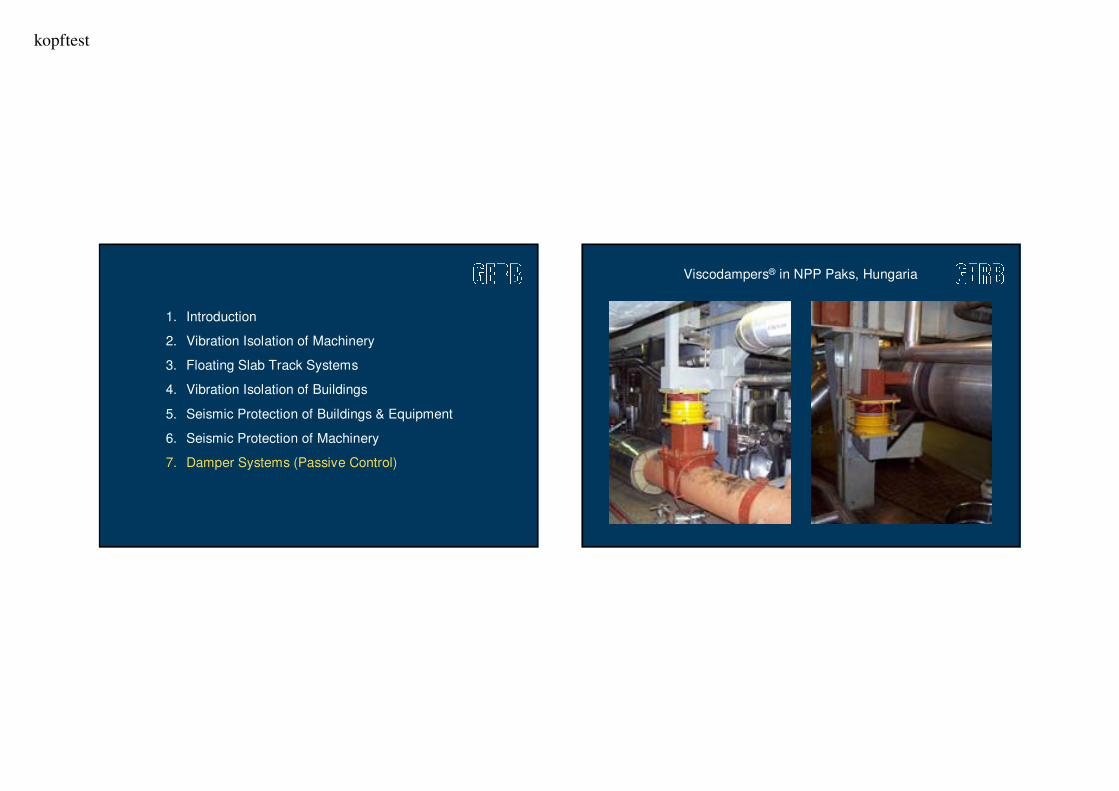
1. Introduction �
2. Vibration Isolation of Machinery
3. Floating Slab Track Systems
4. Vibration Isolation of Buildings
5. Seismic Protection of Buildings & Equipment
6. Seismic Protection of Machinery
7. Damper Systems (Passive Control)
Priciple of Vibration Isolation

kopftest
Metal Forming – Presses and Hammers Transfer Press with Spring Support (Mexico)

kopftest
Fields of Application – Power Plant
Pipework
Damper
Transformer
Diesel Generator Feed Pump
Turbine
Condenser
Floating Floor
Coal Mill
Fan
Priciple of Operation – Turbines

kopftest
0
1
2
3
4
5
6
0 1 2 3 4
Ratio of Frequencies f/f0
Ra
tio
of
Fo
rce
s F
/F0
I [%]
D = 0
D = 0.1
D = 0.2
D = 0.3
F0
F
Mass
High Vibration Isolation Efficiency KW Bellary 500 MW - India

kopftest
Typical Turbine System 1000 MW Typical Turbine System 1000 MW

kopftest
Typical Turbine System 1000 MW Turbine Foundation 1000 MW, China

kopftest
Elastic Support of Fan Foundations Integrated Boiler Feed Pump Foundation

kopftest
Example: Heifei Turbine Building, 300 MW
1. Introduction �
2. Vibration Isolation of Machinery
3. Floating Slab Track Systems
4. Vibration Isolation of Buildings
5. Seismic Protection of Buildings & Equipment
6. Seismic Protection of Machinery
7. Damper Systems (Passive Control)

kopftest
Variations of
Floating Slab Systems
Floating Track Slabs with Steel Springs Floating Slab Track on Top of Station

kopftest
Vibration Control for Trackbeds
The GSI-System

kopftest
Metro Line in Japan
1. Introduction �
2. Vibration Isolation of Machinery
3. Floating Slab Track Systems
4. Vibration Isolation of Buildings
5. Seismic Protection of Buildings & Equipment
6. Seismic Protection of Machinery
7. Damper Systems (Passive Control)

kopftest
2400 seat Concert Hall, Manchester/UK 2400 seat Concert Hall, Manchester/UK

kopftest
2400 seat Concert Hall,
Manchester/UK
Vibration Controlled Buildings

kopftest
1. Introduction
2. Vibration Isolation of Machinery
3. Floating Slab Track Systems
4. Vibration Isolation of Buildings
5. Seismic Protection of Buildings & Equipment
6. Seismic Protection of Machinery
7. Damper Systems (Passive Control)
BCS – Shaking Table Tests / IZIIS Skopje

kopftest
Skopje: Izmit Excitation (Turkey 1999)Mendoza Campus of the
Technical National University of Argentina
Rigid Base ... with BCS

kopftest
Base-Control System in Mendoza
Arrangement ofSpring and Damper
Devices
Mendoza – M5.7 Event on August 5, 2006
X-dir
Y-dir
Z-dir
Measured Excitation
below Buildings

kopftest
Measured Performance of BCS
Acceleration at the Building Top
X-Dir. Y-Dir.
a) b)
Measured Performance of BCS

kopftest
0 50 100 150 200 250 300 350 400 450
Cape Mendocino
Coalinga
Loma Prieta – Corralitos
Imperial Valley, Array Nº 6
Kobe
Chi-Chi –Taiwan
Northridge New Hall
Cape Mendocino, Petrolia
Northridge – Sylmar
Tabas – Iran
Imperial Valley, El Centro
Horizontal Displacement [mm]
Base Isolation System
Base Control System
Structural Responses of Layout Analysis
- Mendoza -
Structural Responses of Layout Analysis
- Mendoza -Brief Characteristics of BIS and BCSBrief Characteristics of BIS and BCS
Spring Systems
Low
Medium
Low
Very low
High
Medium
Medium
Nearly no effect
Easily possible
Medium
Integrated
Spring Systems
Low
Medium
Low
Very low
High
Medium
Medium
Nearly no effect
Easily possible
Medium
Integrated
Rubber Systems
Extremely low
Very high
Very low
Very low
No
Very large
Large
Sometimes problematic
Difficult
High
No
Rubber Systems
Extremely low
Very high
Very low
Very low
No
Very large
Large
Sometimes problematic
Difficult
High
No
Horizontal Stiffness
Vertical Stiffness
Horiz. Acceleration
Stress / Strain Level
Vertical Efficiency
Displacement
Vert. Soil Reaction
Higher Modes
Exchange of Devices
Bearing Capacity
Vibration Isolation / SB Noise
Horizontal Stiffness
Vertical Stiffness
Horiz. Acceleration
Stress / Strain Level
Vertical Efficiency
Displacement
Vert. Soil Reaction
Higher Modes
Exchange of Devices
Bearing Capacity
Vibration Isolation / SB Noise

kopftest
Spent Fuel Storage Tank in high Seismic Zone
Total Supported Weight:
5800 Metric Tons
Design Base Excitation:
0,45-0,55 g (PGA)
Spent Fuel Storage Tank in high Seismic Zone

kopftest
Boiler Structure, Turkey
PGA = 0,40 g
Boiler Structure, Turkey
PGA = 0,40 g
Installation Process below Boiler, TurkeyInstallation Process below Boiler, Turkey
kopftest
Air Core Reactors in Substation, California
Design Ground Motion (IEEE): 1.0 g PGA
System Frequencies with Springs and
VISCODAMPERS®
Rocking: F1 = 0,58 Hz, D1 > 25%
Vertical: F3 = 1,98 Hz, D3 > 30%
Elastic: F7 = 3,7 Hz
Air Core Reactors in Substation, California

kopftest
Seismic Qualification: IEEE Std 693-1997- High Seismic Performance Level -

kopftest
1. Introduction
2. Vibration Isolation of Machinery
3. Floating Slab Track Systems
4. Vibration Isolation of Buildings
5. Seismic Protection of Buildings & Equipment
6. Seismic Protection of Machinery
7. Damper Systems (Passive Control)
Printing Machine
in Sofia
kopftest
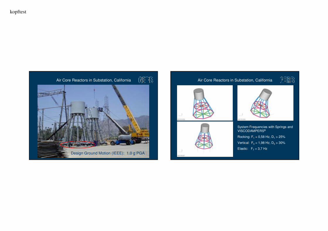
Problems with the Seismic Performance
of Conventional Layout
1. Shaft Acceleration more than 1.0 g
2. Horizontal Relative Displacement more than 100 mm
3. High Stress Levels in the Foundation System
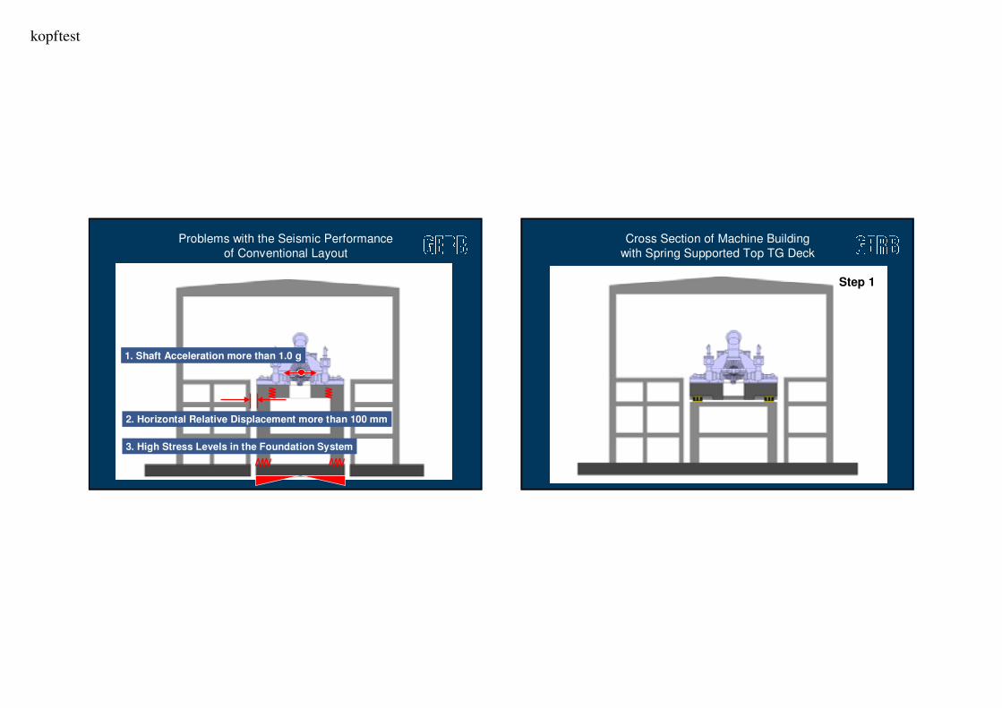
Cross Section of Machine Building
with Spring Supported Top TG Deck
Step 1

kopftest
Spring Supported Turbine Foundation
in High Seismic Zone of Italy
Spring Elements and Dampers are
not shown in the FE Model
First Mode of Foundation System
at 0,8 Hz and
12% of Critical Damping
0,00
0,25
0,50
0,75
1,00
1,25
1,50
0,1 1 10 100
Frequency [Hz]
Ac
ce
lera
tio
n [
g]
Effects of Frequency Reduction on
Seismic Performance

kopftest
0,4
0,5
0,6
0,7
0,8
0,9
1,0
1,1
1,2
1,3
1,4
0 5 10 15 20 25
Damping in %
Co
rre
cti
on
Fa
cto
r ξξ ξξ
Eurocode 8
Uniform Building Code 97
Taiwan Building Code
Architectural Institute Japan
IEEE Std 693-1997
Effects of Damping Increase on
Seismic Performance
Spring Supported TG Deck / Connection
of Substructure and Machine Building
Step 2
kopftest
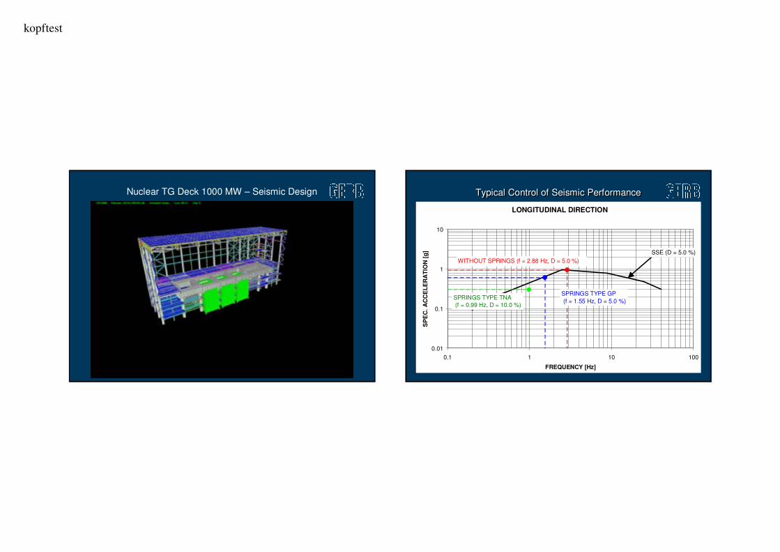
Nuclear TG Deck 1000 MW – Seismic Design
LONGITUDINAL DIRECTION
0.01
0.1
1
10
0.1 1 10 100
FREQUENCY [Hz]
SP
EC
. A
CC
EL
ER
AT
ION
[g
]
SPRINGS TYPE TNA
(f = 0.99 Hz, D = 10.0 %)
WITHOUT SPRINGS (f = 2.88 Hz, D = 5.0 %)
SPRINGS TYPE GP
(f = 1.55 Hz, D = 5.0 %)
SSE (D = 5.0 %)
Typical Control of Seismic PerformanceTypical Control of Seismic Performance
kopftest
1. Introduction
2. Vibration Isolation of Machinery
3. Floating Slab Track Systems
4. Vibration Isolation of Buildings
5. Seismic Protection of Buildings & Equipment
6. Seismic Protection of Machinery
7. Damper Systems (Passive Control)
28
.11.2
01
0
Viscodampers® in NPP Paks, Hungaria

kopftest
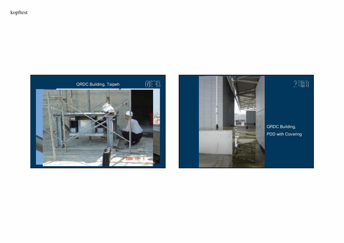
PDD - QRDC Building, Taipeh
QRDC Building
Taipeh
„Prestressed
Damper“
Prestessed Damping Device (PDD)

kopftest
Rigid Connection vs. Prestressed Dampders QRDC Building, Taipeh
kopftest
QRDC Building, Taipeh
QRDC Building,
PDD with Covering

kopftest
PDD Test on Shaking Table in Skopje PDD Test on Shaking Table in Skopje
kopftest
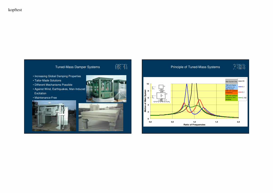
• Increasing Global Damping Properties
• Tailor-Made Solutions
• Different Mechanisms Possible
• Against Wind, Earthquakes, Man-Induced
Excitation
• Maintenance-Free
Tuned-Mass Damper Systems
0
2
4
6
8
10
0,0 0,5 1,0 1,5 2,0
Ratio of Frequencies
Moti
on o
f M
ain
Syste
m
HS
0,1
0,1
0,192
TMD w ith Same
Frequency as
Main System
TMD w ith optimum
Frequency
TMD w ith optimum
Frequency and
Damping
Main System Only
Principle of Tuned-Mass Systems

kopftest
Suspension Bridge in Breslau, Poland Foot Bridge – Without TMD 1st Mode

kopftest
Foot Bridge – Without TMD 2nd Mode Application of TMD - Foot Bridge in Poland

kopftest
Millenium Bridge,
London/UK
The Millennium Bridge, London

kopftest
50 Vertical TMDs
Mass: 1000 – 2000 kg
Tuned Frequency: 1,2 – 2,2 Hz
The Millennium Bridge, London
8 Horizontal TMDs
Mass: 2500 kg
Tuned Frequency: 0,46 Hz
The Millennium Bridge

kopftest
Seismic Protection with Tuned-Mass Systems
TMD 6TMD 7TMD 8
TMD 5
TMD 4
TMD 3
TMD 2
TMD 1
Tuned-Mass System – Mexico

kopftest
DOHA Sport City Tower
Tuned-Mass
Damper in DOHA
Sport City Tower
- 140 tons -
kopftest
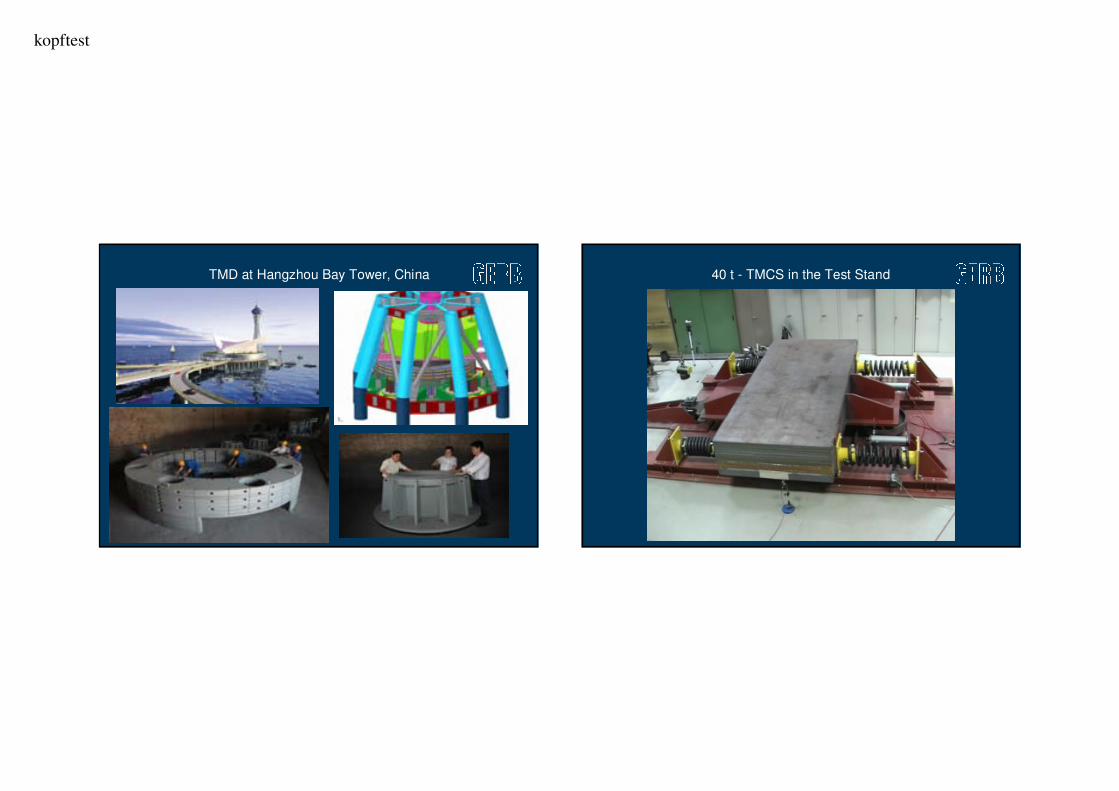
TMD at Hangzhou Bay Tower, China 40 t - TMCS in the Test Stand

kopftest
GERB Vibration Control SystemsBerlin, Germany
Vibration Isolation and Seismic Control Systems
for Machinery, Equipment and BuildingsK.-H. Reinsch
P. Nawrotzki
Athens, November 11, 2010
Thank you !