NTP TimeClient LAN Board - hopf Elektronik GmbH RJ45 Socket (ETH0) ... 7278 / 7278RC NTP TimeClient...
90
_____________________________ Technical Manual NTP TimeClient LAN Board Model 7278 / 7278RC incl. Additional Technical Manual "NTP Output with adjustable Time Base" ENGLISH Version: 02.00 - 11.01.2011 _____________________________________________________________ Valid for Devices 7278 / 7278RC with SET Version: 02.xx IMAGE Version: 02.xx and FIRMWARE Version: 02.xx Industriefunkuhren
Transcript of NTP TimeClient LAN Board - hopf Elektronik GmbH RJ45 Socket (ETH0) ... 7278 / 7278RC NTP TimeClient...
_____________________________
Technical Manual
NTP TimeClient LAN Board
Model 7278 / 7278RC
incl. Additional Technical Manual "NTP Output with adjustable Time Base"
ENGLISH
Version: 02.00 - 11.01.2011
_____________________________________________________________
Valid for Devices 7278 / 7278RC with SET Version: 02.xx
IMAGE Version: 02.xx and FIRMWARE Version: 02.xx
Industriefunkuhren

2 / 90 7278 / 7278RC NTP TimeClient LAN Board - V02.00
hopf Elektronik GmbH
Nottebohmstr. 41 • D-58511 Lüdenscheid • Tel.: +49 (0)2351 9386-86 • Fax: +49 (0)2351 9386-93 • Internet: http://www.hopf.com • E-Mail: [email protected]
INPORTANT NOTES
7278 / 7278RC NTP TimeClient LAN Board - V02.00 3 / 90
hopf Elektronik GmbH
Nottebohmstr. 41 • D-58511 Lüdenscheid • Tel.: +49 (0)2351 9386-86 • Fax: +49 (0)2351 9386-93 • Internet: http://www.hopf.com • E-Mail: [email protected]
Version Numbers (Firmware / Description)
THE TERM SET DEFINES THE FIXED RELATIONSHIP BETWEEN THE IMAGE VERSION
AND THE ASSOCIATED H8 FIRMWARE VERSION.
THE FIRST TWO DIGITS OF THE TECHNICAL DESCRIPTION VERSION NUMBER, THE
SET VERSION AND THE IMAGE VERSION MUST BE THE SAME! THEY DESIGNATE
THE SHARED FUNCTIONAL IDENTITY BETWEEN DEVICE, SOFTWARE AND TECHNICAL
DESCRIPTION.
THE VERSION NUMBER OF THE IMAGE AND THE H8 SOFTWARE CAN BE READ IN THE
WEBGUI OF BOARD 7278(RC) (SEE CHAPTER 7.3.6.1 Device Information AND
CHAPTER 7.3.6.2 Hardware Information).
THE TWO DIGITS AFTER THE DOT IN THE VERSION NUMBER DESIGNATE
CORRECTIONS TO THE FIRMWARE AND/OR DESCRIPTION WHICH HAVE NO EFFECT
ON FUNCTIONALITY.
Downloading Technical Manuals
All current manuals of our products are available free of charge via our homepage on the Internet.
Homepage: http://www.hopf.com
E-mail: [email protected]
Symbols and Characters
Operational Reliability Disregard may cause damages to persons or material.
Functionality Disregard may impact function of system/device.
Information Notes and Information.
SERVICE RELIABILITY
4 / 90 7278 / 7278RC NTP TimeClient LAN Board - V02.00
hopf Elektronik GmbH
Nottebohmstr. 41 • D-58511 Lüdenscheid • Tel.: +49 (0)2351 9386-86 • Fax: +49 (0)2351 9386-93 • Internet: http://www.hopf.com • E-Mail: [email protected]
Safety regulations The safety regulations and observance of the technical data serve to ensure trouble-free operation of the device and protection of persons and material. It is therefore of utmost importance to observe and compliance with these regulations.
If these are not complied with, then no claims may be made under the terms of the warranty. No liability will be assumed for any ensuing damage.
Safety of the device This device has been manufactured in accordance with the latest technological standards and approved safety regulations
The device should only be put into operation by trained and qualified staff. Care must be taken that all cable connections are laid and fixed in position correctly. The device should only be operated with the voltage supply indicated on the identification label.
The device should only be operated by qualified staff or employees who have received specific instruction.
If a device must be opened for repair, this should only be carried out by
employees with appropriate qualifications or by hopf Elektronik GmbH.
Before a device is opened or a fuse is changed all power supplies must be disconnected.
If there are reasons to believe that the operational safety can no longer be guaranteed the device must be taken out of service and labelled accordingly.
The safety may be impaired when the device does not operate properly or if it is obviously damaged.
CE-Conformity
This device fulfils the requirements of the EU directive 89/336/EWG "Electromagnetic compatibility" and 73/23/EWG "Low voltage equipment".
Therefore the device bears the CE identification marking (CE = Communautés Européennes = European communities)
The CE indicates to the controlling bodies that the product complies with the requirements of the EU directive - especially with regard to protection of health and safety for the operator and the user - and may be released for sale within the common markets.
TABLE OF CONTENTS
7278 / 7278RC NTP TimeClient LAN Board - V02.00 5 / 90
hopf Elektronik GmbH
Nottebohmstr. 41 • D-58511 Lüdenscheid • Tel.: +49 (0)2351 9386-86 • Fax: +49 (0)2351 9386-93 • Internet: http://www.hopf.com • E-Mail: [email protected]
Contents Page
1 General ............................................................................................................................ 9
2 Board 7278(RC) Basic Functions ................................................................................ 10
3 Board 7278(RC) Construction ..................................................................................... 11
3.1 Board 7278(RC) Front Panel .................................................................................... 11 3.1.1 Status LEDs of the Board 7278(RC) .................................................................................. 12 3.1.2 RJ45 Socket (ETH0) .......................................................................................................... 13 3.1.3 Reset / Default Button ........................................................................................................ 13
3.2 Overview of Board 7278(RC) (3U/4HP) Assembly.................................................... 14 3.2.1 DIP Switch DS1 of Board 7278(RC) .................................................................................. 14 3.2.2 MAC Address Labels ......................................................................................................... 15 3.2.3 Heat Sink ............................................................................................................................ 15
4 Board 7278(RC) System Performance ........................................................................ 16
4.1 Delayed Readiness for Operation after Switch-on / Reset ........................................ 16
4.2 Reset / Default Button ............................................................................................... 16 4.2.1 Board Reset ....................................................................................................................... 16 4.2.2 Set LAN Parameters in Default Status ............................................................................... 17
5 Implementing Board 7278(RC) in a hopf Base System ............................................ 18
5.1 Implementation in Base System 68xx or 7001 .......................................................... 18
5.1.1 Select the hopf Base System 68xx or 7001 ..................................................................... 18
5.1.2 Setting the System Board Number .................................................................................... 19 5.1.2.1 Setting the Board Number for Base System 7001 ...................................................................... 19 5.1.2.2 Setting the Board Number for Base System 68xx ....................................................................... 20
5.1.3 Creating the Network Connection ...................................................................................... 20
5.2 Implementing in hopf Base System 7001RC ........................................................... 21
5.2.1 Setting the System Board Number .................................................................................... 21 5.2.2 Setting the Board Number for Base System 7001RC ........................................................ 22 5.2.3 Creating the Network Connection ...................................................................................... 23
6 Network Configuration for ETH0 via the Base System ............................................. 24
6.1 Input Functions of Base Systems 6842, 6850 and 6855 ........................................... 26 6.1.1 Inputting the Static IPv4 Address / DHCP Mode ............................................................... 26 6.1.2 Inputting the Gateway Address .......................................................................................... 27 6.1.3 Inputting the Network Mask ............................................................................................... 27 6.1.4 Inputting the Control Byte (no function at present) ............................................................ 28
6.2 Base System 7001 Input Functions .......................................................................... 29 6.2.1 Inputting the Control Byte (no function at present) ............................................................ 29 6.2.2 Inputting the Static IPv4 Address / DHCP Mode ............................................................... 30 6.2.3 Inputting the Network Mask ............................................................................................... 30 6.2.4 Inputting the Gateway Address .......................................................................................... 30
6.3 Input Functions of Base Systems 7001RC ............................................................... 31 6.3.1 Inputting the Static IPv4 Address / DHCP Mode ............................................................... 31
TABLE OF CONTENTS
6 / 90 7278 / 7278RC NTP TimeClient LAN Board - V02.00
hopf Elektronik GmbH
Nottebohmstr. 41 • D-58511 Lüdenscheid • Tel.: +49 (0)2351 9386-86 • Fax: +49 (0)2351 9386-93 • Internet: http://www.hopf.com • E-Mail: [email protected]
6.3.2 Inputting the Gateway Address .......................................................................................... 32 6.3.3 Inputting the Network Mask ............................................................................................... 32 6.3.4 Inputting the Control-Byte .................................................................................................. 32
6.3.4.1 Bit 7-1 - No Function at Present .................................................................................................. 32 6.3.4.2 Bit 0 - Restoring Factory Settings ............................................................................................... 33
6.3.5 Inputting the Parameterbyte 01 (no function at present) ................................................... 33 6.3.6 Inputting the Parameterbyte 02 (no function at present) ................................................... 33
6.4 Network Parameter Configuration via HMC .............................................................. 34
7 HTTP/HTTPS WebGUI – Web Browser Configuration Interface ............................... 36
7.1 Quick Configuration ................................................................................................... 36 7.1.1 Requirements ..................................................................................................................... 36 7.1.2 Configuration Steps ............................................................................................................ 36
7.2 General – Introduction ............................................................................................... 37 7.2.1 LOGIN and LOGOUT as a User ........................................................................................ 38 7.2.2 Navigation through the Web Interface ............................................................................... 39 7.2.3 Inputting or Changing Data ................................................................................................ 40 7.2.4 Plausibility Check during Input ........................................................................................... 41
7.3 Description of the Tabs ............................................................................................. 42 7.3.1 GENERAL Tab ................................................................................................................... 42 7.3.2 TIME Tab ........................................................................................................................... 44
7.3.2.1 Time Zone Offset ........................................................................................................................ 44 7.3.2.2 Configuration of Summer Time (Daylight Saving Time) .............................................................. 45
7.3.3 NETWORK Tab .................................................................................................................. 46 7.3.3.1 Host/Nameservice ...................................................................................................................... 46
7.3.3.1.1 Hostname 46 7.3.3.1.2 Default Gateway 47 7.3.3.1.3 DNS Server 1 & 2 47
7.3.3.2 Network Interface ETH0 .............................................................................................................. 48 7.3.3.2.1 Default Hardware Address (MAC) 48 7.3.3.2.2 DHCP 48 7.3.3.2.3 IP Address 49 7.3.3.2.4 Network Mask 49 7.3.3.2.5 Operation Mode 49
7.3.3.3 Routing ....................................................................................................................................... 50 7.3.3.4 Management-Protocols / SNMP ................................................................................................. 51
7.3.4 NTP Tab ............................................................................................................................. 52 7.3.4.1 System Info ................................................................................................................................. 52 7.3.4.2 Kernel Info .................................................................................................................................. 53 7.3.4.3 Peers .......................................................................................................................................... 53 7.3.4.4 Server Configuration ................................................................................................................... 54
7.3.4.4.1 NTP SERVERS for Synchronisation 54 7.3.4.4.2 Broadcast / Multicast 55
7.3.4.5 Client Configuration .................................................................................................................... 55 7.3.4.6 Restart NTP ................................................................................................................................ 58 7.3.4.7 Access Restrictions / Configuring the NTP Service Restrictions ................................................. 59
7.3.4.7.1 NAT or Firewall 60 7.3.4.7.2 Blocking Unauthorised Access 60 7.3.4.7.3 Allow Client Requests 60 7.3.4.7.4 Internal Client Protection / Local Network Threat Level 61 7.3.4.7.5 Addition of Exceptions to Standard Restrictions 61 7.3.4.7.6 Access Control Options 62
7.3.4.8 Symmetric Key ............................................................................................................................ 63 7.3.4.8.1 Why Authentication? 64 7.3.4.8.2 How is Authentication used in the NTP Service? 64 7.3.4.8.3 How is a key created? 64 7.3.4.8.4 How does authentication work? 64
TABLE OF CONTENTS
7278 / 7278RC NTP TimeClient LAN Board - V02.00 7 / 90
hopf Elektronik GmbH
Nottebohmstr. 41 • D-58511 Lüdenscheid • Tel.: +49 (0)2351 9386-86 • Fax: +49 (0)2351 9386-93 • Internet: http://www.hopf.com • E-Mail: [email protected]
7.3.4.9 Autokey / Public Key Cryptography ............................................................................................ 65 7.3.5 ALARM Tab ........................................................................................................................ 66
7.3.5.1 Syslog Configuration ................................................................................................................... 66 7.3.5.2 E-mail Configuration ................................................................................................................... 67 7.3.5.3 SNMP Configuration / TRAP Configuration ................................................................................ 68 7.3.5.4 Alarm Messages ......................................................................................................................... 69
7.3.6 DEVICE Tab ....................................................................................................................... 70 7.3.6.1 Device Information ...................................................................................................................... 70 7.3.6.2 Hardware Information ................................................................................................................. 71 7.3.6.3 Factory Defaults .......................................................................................................................... 72 7.3.6.4 Reboot Device ............................................................................................................................ 72 7.3.6.5 Image Update & H8 Firmware Update ........................................................................................ 73 7.3.6.6 Upload Certificate ....................................................................................................................... 74 7.3.6.7 Passwords .................................................................................................................................. 75 7.3.6.8 Downloading SNMP MIB / Configuration Files ............................................................................ 75 7.3.6.9 Accuracy (Low / Medium / High) ................................................................................................. 76
8 SSH and Telnet Basic Configuration .......................................................................... 77
9 Technical Data .............................................................................................................. 78
9.1 General ..................................................................................................................... 78 9.1.1 Design ................................................................................................................................ 78 9.1.2 Ambient conditions ............................................................................................................. 78 9.1.3 CE compliant ...................................................................................................................... 78 9.1.4 NTP Accuracy .................................................................................................................... 78 9.1.5 Time Protocols ................................................................................................................... 79 9.1.6 TCP/IP Network Protocols ................................................................................................. 79 9.1.7 Configuration ...................................................................................................................... 79 9.1.8 Features ............................................................................................................................. 79
9.2 Special Technical Data of Board 7278(RC) .............................................................. 79
10 Factory Defaults ............................................................................................................ 80
10.1 Network ..................................................................................................................... 80
10.2 NTP ........................................................................................................................... 81
10.3 ALARM ...................................................................................................................... 81
10.4 DEVICE ..................................................................................................................... 81
11 Glossary and Abbreviations ........................................................................................ 82
11.1 NTP-specific terminology .......................................................................................... 82
11.2 Tally Codes (NTP-specific) ....................................................................................... 82
11.3 Time-specific expressions ......................................................................................... 83
11.4 Abbreviations ............................................................................................................ 84
11.5 Definitions ................................................................................................................. 85 11.5.1 DHCP (Dynamic Host Configuration Protocol) .................................................................. 85 11.5.2 NTP (Network Time Protocol) ............................................................................................ 85 11.5.3 SNMP (Simple Network Management Protocol) ................................................................ 86 11.5.4 TCP/IP (Transmission Control Protocol / Internet Protocol) .............................................. 86
11.6 Accuracy & NTP Basic Principles ............................................................................. 87

TABLE OF CONTENTS
8 / 90 7278 / 7278RC NTP TimeClient LAN Board - V02.00
hopf Elektronik GmbH
Nottebohmstr. 41 • D-58511 Lüdenscheid • Tel.: +49 (0)2351 9386-86 • Fax: +49 (0)2351 9386-93 • Internet: http://www.hopf.com • E-Mail: [email protected]
12 List of RFCs ................................................................................................................... 89
13 List of Open Source Packages used ........................................................................... 90
GENERAL
7278 / 7278RC NTP TimeClient LAN Board - V02.00 9 / 90
hopf Elektronik GmbH
Nottebohmstr. 41 • D-58511 Lüdenscheid • Tel.: +49 (0)2351 9386-86 • Fax: +49 (0)2351 9386-93 • Internet: http://www.hopf.com • E-Mail: [email protected]
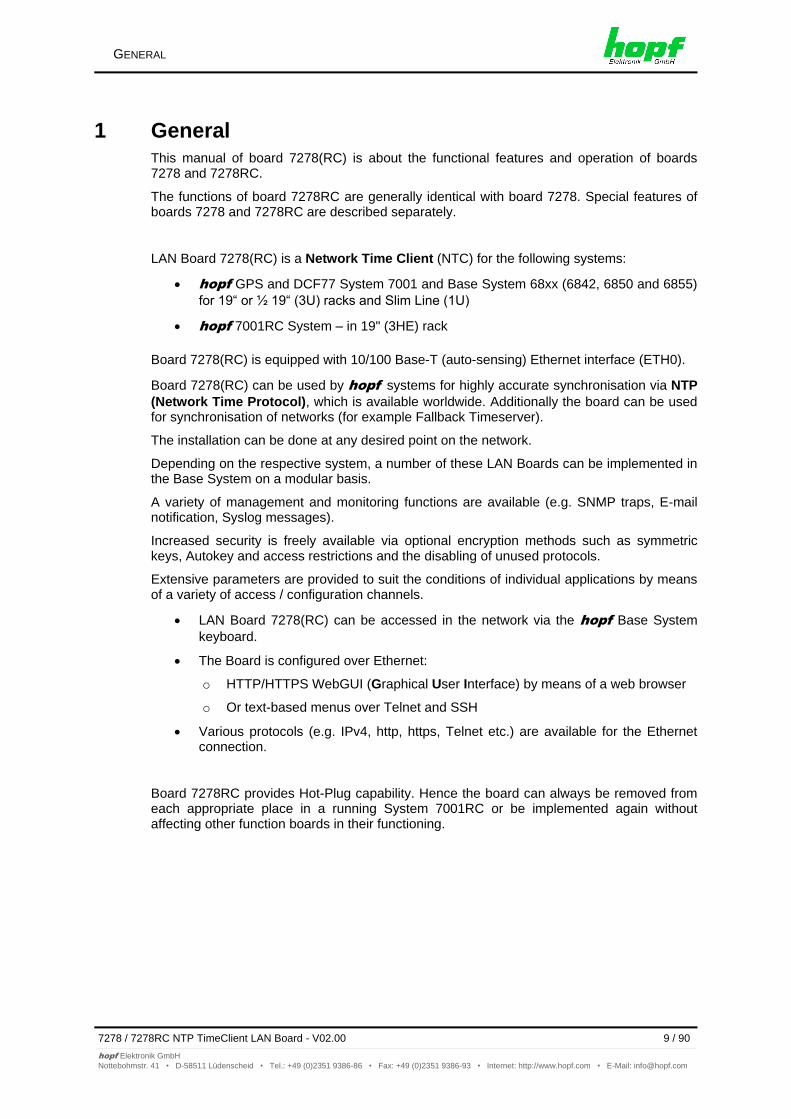
1 General This manual of board 7278(RC) is about the functional features and operation of boards 7278 and 7278RC.
The functions of board 7278RC are generally identical with board 7278. Special features of boards 7278 and 7278RC are described separately.
LAN Board 7278(RC) is a Network Time Client (NTC) for the following systems:
hopf GPS and DCF77 System 7001 and Base System 68xx (6842, 6850 and 6855)
for 19“ or ½ 19“ (3U) racks and Slim Line (1U)
hopf 7001RC System – in 19" (3HE) rack
Board 7278(RC) is equipped with 10/100 Base-T (auto-sensing) Ethernet interface (ETH0).
Board 7278(RC) can be used by hopf systems for highly accurate synchronisation via NTP
(Network Time Protocol), which is available worldwide. Additionally the board can be used for synchronisation of networks (for example Fallback Timeserver).
The installation can be done at any desired point on the network.
Depending on the respective system, a number of these LAN Boards can be implemented in the Base System on a modular basis.
A variety of management and monitoring functions are available (e.g. SNMP traps, E-mail notification, Syslog messages).
Increased security is freely available via optional encryption methods such as symmetric keys, Autokey and access restrictions and the disabling of unused protocols.
Extensive parameters are provided to suit the conditions of individual applications by means of a variety of access / configuration channels.
LAN Board 7278(RC) can be accessed in the network via the hopf Base System
keyboard.
The Board is configured over Ethernet:
o HTTP/HTTPS WebGUI (Graphical User Interface) by means of a web browser
o Or text-based menus over Telnet and SSH
Various protocols (e.g. IPv4, http, https, Telnet etc.) are available for the Ethernet connection.
Board 7278RC provides Hot-Plug capability. Hence the board can always be removed from each appropriate place in a running System 7001RC or be implemented again without affecting other function boards in their functioning.
BOARD 7278(RC) BASIC FUNCTIONS
10 / 90 7278 / 7278RC NTP TimeClient LAN Board - V02.00
hopf Elektronik GmbH
Nottebohmstr. 41 • D-58511 Lüdenscheid • Tel.: +49 (0)2351 9386-86 • Fax: +49 (0)2351 9386-93 • Internet: http://www.hopf.com • E-Mail: [email protected]
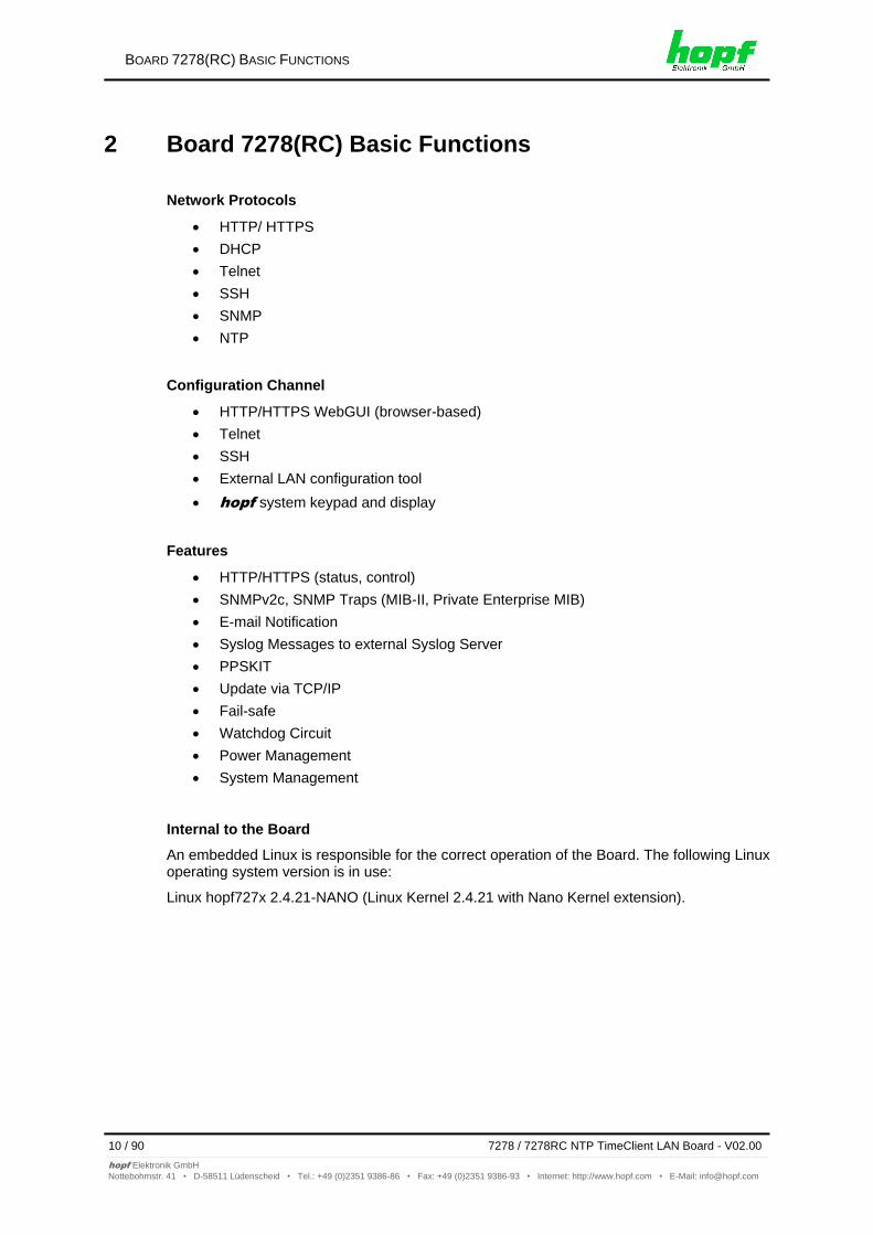
2 Board 7278(RC) Basic Functions
Network Protocols
HTTP/ HTTPS
DHCP
Telnet
SSH
SNMP
NTP
Configuration Channel
HTTP/HTTPS WebGUI (browser-based)
Telnet
SSH
External LAN configuration tool
hopf system keypad and display
Features
HTTP/HTTPS (status, control)
SNMPv2c, SNMP Traps (MIB-II, Private Enterprise MIB)
E-mail Notification
Syslog Messages to external Syslog Server
PPSKIT
Update via TCP/IP
Fail-safe
Watchdog Circuit
Power Management
System Management
Internal to the Board
An embedded Linux is responsible for the correct operation of the Board. The following Linux operating system version is in use:
Linux hopf727x 2.4.21-NANO (Linux Kernel 2.4.21 with Nano Kernel extension).
BOARD 7278(RC) CONSTRUCTION
7278 / 7278RC NTP TimeClient LAN Board - V02.00 11 / 90
hopf Elektronik GmbH
Nottebohmstr. 41 • D-58511 Lüdenscheid • Tel.: +49 (0)2351 9386-86 • Fax: +49 (0)2351 9386-93 • Internet: http://www.hopf.com • E-Mail: [email protected]
3 Board 7278(RC) Construction This Chapter describes the hardware components of Board 7278(RC).
3.1 Board 7278(RC) Front Panel
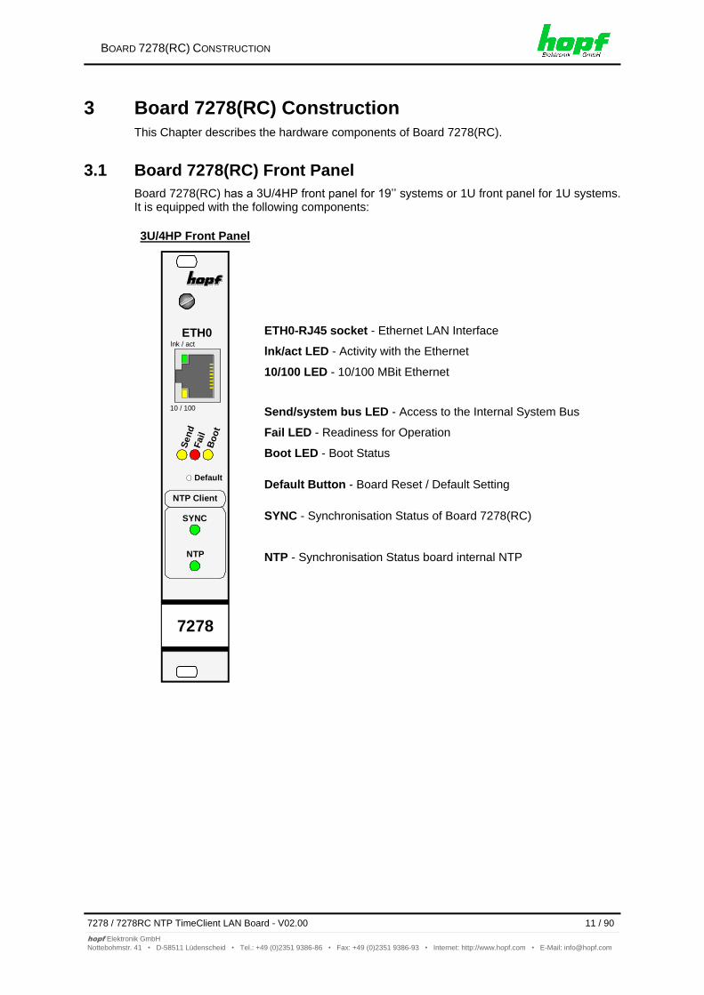
Board 7278(RC) has a 3U/4HP front panel for 19’’ systems or 1U front panel for 1U systems. It is equipped with the following components:
3U/4HP Front Panel
Sen
dF
ail
Bo
ot
Default
ETH0
10 / 100
lnk / act
7278
NTP Client
SYNC
NTP
ETH0-RJ45 socket - Ethernet LAN Interface
lnk/act LED - Activity with the Ethernet
10/100 LED - 10/100 MBit Ethernet
Send/system bus LED - Access to the Internal System Bus
Fail LED - Readiness for Operation
Boot LED - Boot Status
Default Button - Board Reset / Default Setting
SYNC - Synchronisation Status of Board 7278(RC)
NTP - Synchronisation Status board internal NTP
BOARD 7278(RC) CONSTRUCTION
12 / 90 7278 / 7278RC NTP TimeClient LAN Board - V02.00
hopf Elektronik GmbH
Nottebohmstr. 41 • D-58511 Lüdenscheid • Tel.: +49 (0)2351 9386-86 • Fax: +49 (0)2351 9386-93 • Internet: http://www.hopf.com • E-Mail: [email protected]
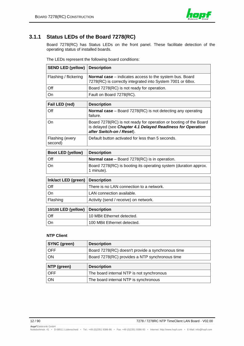
3.1.1 Status LEDs of the Board 7278(RC)
Board 7278(RC) has Status LEDs on the front panel. These facilitate detection of the operating status of installed boards.
The LEDs represent the following board conditions:
SEND LED (yellow) Description
Flashing / flickering Normal case – indicates access to the system bus. Board 7278(RC) is correctly integrated into System 7001 or 68xx.
Off Board 7278(RC) is not ready for operation.
On Fault on Board 7278(RC).
Fail LED (red) Description
Off Normal case – Board 7278(RC) is not detecting any operating failure.
On Board 7278(RC) is not ready for operation or booting of the Board is delayed (see Chapter 4.1 Delayed Readiness for Operation after Switch-on / Reset).
Flashing (every second)
Default button activated for less than 5 seconds.
Boot LED (yellow) Description
Off Normal case – Board 7278(RC) is in operation.
On Board 7278(RC) is booting its operating system (duration approx. 1 minute).
lnk/act LED (green) Description
Off There is no LAN connection to a network.
On LAN connection available.
Flashing Activity (send / receive) on network.
10/100 LED (yellow) Description
Off 10 MBit Ethernet detected.
On 100 MBit Ethernet detected.
NTP Client
SYNC (green) Description
OFF Board 7278(RC) doesn't provide a synchronous time
ON Board 7278(RC) provides a NTP synchronous time
NTP (green) Description
OFF The board internal NTP is not synchronous
ON The board internal NTP is synchronous
BOARD 7278(RC) CONSTRUCTION
7278 / 7278RC NTP TimeClient LAN Board - V02.00 13 / 90
hopf Elektronik GmbH
Nottebohmstr. 41 • D-58511 Lüdenscheid • Tel.: +49 (0)2351 9386-86 • Fax: +49 (0)2351 9386-93 • Internet: http://www.hopf.com • E-Mail: [email protected]
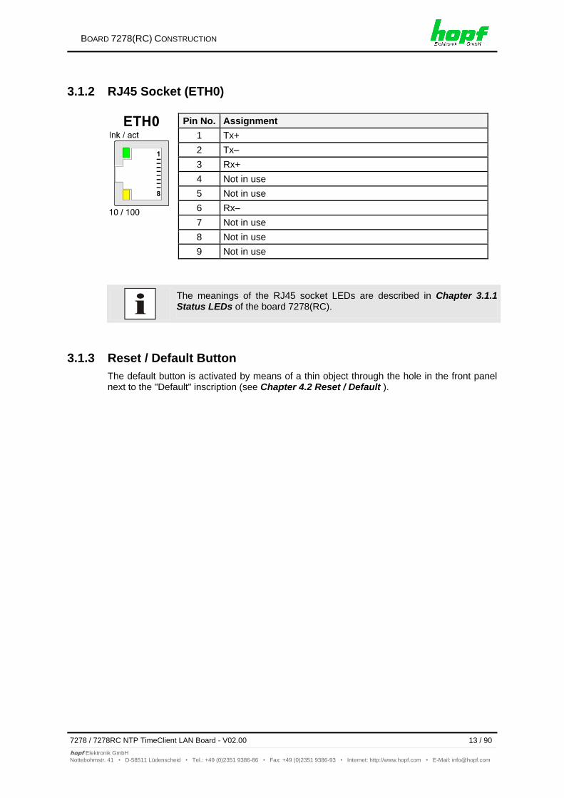
3.1.2 RJ45 Socket (ETH0)
Pin No. Assignment
1 Tx+
2 Tx–
3 Rx+
4 Not in use
5 Not in use
6 Rx–
7 Not in use
8 Not in use
9 Not in use
The meanings of the RJ45 socket LEDs are described in Chapter 3.1.1 Status LEDs of the board 7278(RC).
3.1.3 Reset / Default Button
The default button is activated by means of a thin object through the hole in the front panel next to the "Default" inscription (see Chapter 4.2 Reset / Default ).
BOARD 7278(RC) CONSTRUCTION
14 / 90 7278 / 7278RC NTP TimeClient LAN Board - V02.00
hopf Elektronik GmbH
Nottebohmstr. 41 • D-58511 Lüdenscheid • Tel.: +49 (0)2351 9386-86 • Fax: +49 (0)2351 9386-93 • Internet: http://www.hopf.com • E-Mail: [email protected]
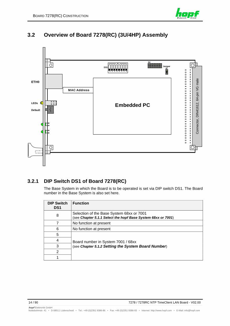
3.2 Overview of Board 7278(RC) (3U/4HP) Assembly
ETH0
LEDs
Default
onX4
DS1Jumper
J2
MAC Address
Embedded PC
Connecto
r, D
IN41612, 64-p
in V
G m
ale
3.2.1 DIP Switch DS1 of Board 7278(RC)
The Base System in which the Board is to be operated is set via DIP switch DS1. The Board number in the Base System is also set here.
DIP Switch DS1
Function
8 Selection of the Base System 68xx or 7001 (see Chapter 5.1.1 Select the hopf Base System 68xx or 7001)
7 No function at present
6 No function at present
5
Board number in System 7001 / 68xx (see Chapter 5.1.2 Setting the System Board Number)
4
3
2
1
BOARD 7278(RC) CONSTRUCTION
7278 / 7278RC NTP TimeClient LAN Board - V02.00 15 / 90
hopf Elektronik GmbH
Nottebohmstr. 41 • D-58511 Lüdenscheid • Tel.: +49 (0)2351 9386-86 • Fax: +49 (0)2351 9386-93 • Internet: http://www.hopf.com • E-Mail: [email protected]
3.2.2 MAC Address Labels
Each LAN interface is uniquely identifiable in the Ethernet by means of a MAC address (hardware address). The MAC address of the respective LAN interface can be found on the
label assigned to the interface. A unique MAC address is assigned by hopf Elektronik
GmbH for each LAN interface.
hopf Elektronik GmbH MAC addresses begin with 00:03:C7:xx:xx:xx.
3.2.3 Heat Sink
Due to the installation height, care should be taken to ensure that the heat sink does not make contact with surrounding system components when removing or inserting Board 7278(RC).
BOARD 7278(RC) SYSTEM PERFORMANCE
16 / 90 7278 / 7278RC NTP TimeClient LAN Board - V02.00
hopf Elektronik GmbH
Nottebohmstr. 41 • D-58511 Lüdenscheid • Tel.: +49 (0)2351 9386-86 • Fax: +49 (0)2351 9386-93 • Internet: http://www.hopf.com • E-Mail: [email protected]
4 Board 7278(RC) System Performance Performance of Board 7278(RC) when switching on and resetting the Base System and when activating the default button on the front panel.
4.1 Delayed Readiness for Operation after Switch-on / Reset
Board 7278(RC) requires an increased supply current during the boot procedure (Board start-up). In order to guarantee the power management of the system, booting of the Board is delayed dependent on the set System Board number.
The red Fail LED on the front panel lights up during the delay phase.
Booting delay = Board number x 30 seconds
4.2 Reset / Default Button
Board 7278(RC) can be reset or placed in default status with the aid of the default button which is located behind the Board’s front panel. The default button can be accessed by means of a thin object through a small hole in the front panel.
Default Button Description
Press for approx. 1 second Trigger Board reset (see Chapter 4.2.1 Board Reset)
Press for more than 5 seconds
Place Board in default status (see Chapter 4.2.2 Set LAN Parameters in Default Status)
4.2.1 Board Reset
A reset is triggered on Board 7278(RC) by briefly pressing the default button (approx. 1-2 seconds).
The Board Reset releases a Reset in the Base System. (Exception: System 7001RC)
Trigger Board reset with the default button:
1. Briefly press default button (approx. 1-2 seconds).
2. Board reset takes place maximum 5 seconds after releasing the default button.
3. Red Fail LED lights up Board 7278(RC) is not yet ready for operation.
4. Yellow Send LED flickers Board 7278(RC) is integrated into the Base System.
5. Red Fail LED goes out and yellow Boot LED lights up the Board begins to boot depending on the set Board number (the boot process can take up to one minute).
6. Full operating status is obtained when:
Send LED flickers
Fail LED is not lit
Boot LED is not lit
Board 7278(RC) is not immediately accessible following a reset (see Chapter 4.1 Delayed Readiness for Operation after Switch-on / Reset).
BOARD 7278(RC) SYSTEM PERFORMANCE
7278 / 7278RC NTP TimeClient LAN Board - V02.00 17 / 90
hopf Elektronik GmbH
Nottebohmstr. 41 • D-58511 Lüdenscheid • Tel.: +49 (0)2351 9386-86 • Fax: +49 (0)2351 9386-93 • Internet: http://www.hopf.com • E-Mail: [email protected]
4.2.2 Set LAN Parameters in Default Status
Board 7278(RC) can be set in default status by means of the default button in the event that the Board is no longer reachable on the Ethernet following incorrect configuration (e.g. over the Ethernet).
If the default button is pressed for longer than 5 seconds, the following LAN parameters which are stored on the Board are set in the DHCP mode:
IP 000.000.000.000
Gateway 000.000.000.000
Network mask 000.000.000.000
The Base System will release a Reset after setting the Board 7278(RC) into default status. (Exception: System 7001RC)
The parameters changed via the default button are not updated in the Base System and thus are no longer displayed correctly in the Base System menu following the default. (Exception: System 7001RC) Board 7278(RC) must be completely configured via the Base System, including entry of the LAN parameters, following the default.
All other configurations can only be set to default status via the Ethernet interface (see Chapter 7.3.6.3 Factory Defaults).
Set Board 7278(RC) to default status.
1. Press the default button
2. Red Fail LED flashes every second until "Trigger Default" is reached (after approx. 5 seconds)
3. Release the default button
4. Board 7278(RC) takes over the default settings
5. Board 7278(RC) triggers a Board reset
6. Create accessibility to the Ethernet ETH0 via the Base System (reset the IP address, gateway and network mask via the Base System menu)
7. Check all configurations in the WebGUI and re-set if necessary
IMPLEMENTING BOARD 7278(RC) IN A HOPF BASE SYSTEM
18 / 90 7278 / 7278RC NTP TimeClient LAN Board - V02.00
hopf Elektronik GmbH
Nottebohmstr. 41 • D-58511 Lüdenscheid • Tel.: +49 (0)2351 9386-86 • Fax: +49 (0)2351 9386-93 • Internet: http://www.hopf.com • E-Mail: [email protected]
5 Implementing Board 7278(RC) in a hopf Base System
Each LAN Board is uniquely identified in a hopf Base System via an
assigned Board number
5.1 Implementation in Base System 68xx or 7001
The following steps are required for the purpose of implementation:
Fixed wired slot in the System 7001 (see also system drawing)
Not more than 1 LAN Board (System 68xx) or 7 LAN Boards (System 7001) already implemented
Set the Base System (System 68xx or System 7001) in which the Board is to be implemented via the DIP switch on Board 7278
Set a LAN Board number that is not yet assigned in the Base System via the DIP switch on Board 7278 (System 68xx: max. No. 2; System 7001: max. No.8)
Switch the Base System off
Remove the Bus Bridge Board from the Base System
Insert the LAN Board
Switch the System on
Select the LAN Board setting menu in the Base System (LAN x / x = set Board number)
Set the desired LAN parameters (IP, network mask and gateway) via the menu
Configure LAN Board 7278 over WebGUI and Ethernet
5.1.1 Select the hopf Base System 68xx or 7001
Selection can be made to operate the Board in Base System 7001 or Base Systems 6842, 6850 or 6855 by means of switch 8 on dip switch bank DS1.
Board 7278 will only operate properly if this setting is correct.
SW8 hopf Base System Selection
off Base System 7001
on Base System 68xx
IMPLEMENTING BOARD 7278(RC) IN A HOPF BASE SYSTEM
7278 / 7278RC NTP TimeClient LAN Board - V02.00 19 / 90
hopf Elektronik GmbH
Nottebohmstr. 41 • D-58511 Lüdenscheid • Tel.: +49 (0)2351 9386-86 • Fax: +49 (0)2351 9386-93 • Internet: http://www.hopf.com • E-Mail: [email protected]
5.1.2 Setting the System Board Number
The boards must be coded to a System Board number in order to enable the various LAN Boards to be administered and configured in the Base System.
Under no circumstances may two LAN Boards with the same Board number be integrated into one Base System. This leads to unspecified faults on these two Boards!
The coding of the Board number takes place on Board 7278 via DIP switch bank (DS1).
The numbering of the Boards displayed in the WebGUI (Board No. X) begins at 0. This means, for example, that LAN Board 1 is denoted by 0 in the WebGUI and LAN Board 8 is denoted by 7.
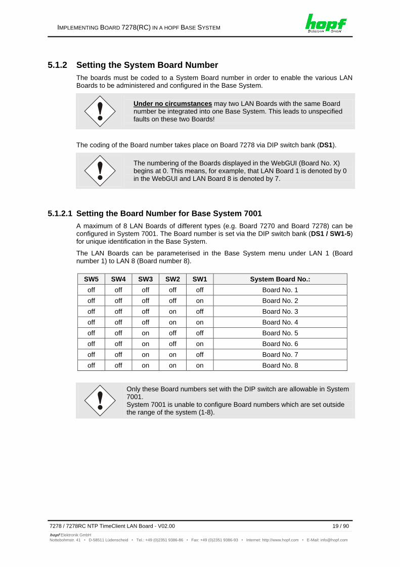
5.1.2.1 Setting the Board Number for Base System 7001
A maximum of 8 LAN Boards of different types (e.g. Board 7270 and Board 7278) can be configured in System 7001. The Board number is set via the DIP switch bank (DS1 / SW1-5) for unique identification in the Base System.
The LAN Boards can be parameterised in the Base System menu under LAN 1 (Board number 1) to LAN 8 (Board number 8).
SW5 SW4 SW3 SW2 SW1 System Board No.:
off off off off off Board No. 1
off off off off on Board No. 2
off off off on off Board No. 3
off off off on on Board No. 4
off off on off off Board No. 5
off off on off on Board No. 6
off off on on off Board No. 7
off off on on on Board No. 8
Only these Board numbers set with the DIP switch are allowable in System 7001. System 7001 is unable to configure Board numbers which are set outside the range of the system (1-8).
IMPLEMENTING BOARD 7278(RC) IN A HOPF BASE SYSTEM
20 / 90 7278 / 7278RC NTP TimeClient LAN Board - V02.00
hopf Elektronik GmbH
Nottebohmstr. 41 • D-58511 Lüdenscheid • Tel.: +49 (0)2351 9386-86 • Fax: +49 (0)2351 9386-93 • Internet: http://www.hopf.com • E-Mail: [email protected]
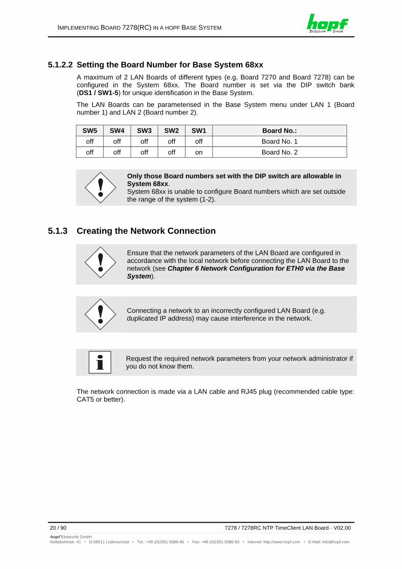
5.1.2.2 Setting the Board Number for Base System 68xx
A maximum of 2 LAN Boards of different types (e.g. Board 7270 and Board 7278) can be configured in the System 68xx. The Board number is set via the DIP switch bank (DS1 / SW1-5) for unique identification in the Base System.
The LAN Boards can be parameterised in the Base System menu under LAN 1 (Board number 1) and LAN 2 (Board number 2).
SW5 SW4 SW3 SW2 SW1 Board No.:
off off off off off Board No. 1
off off off off on Board No. 2
Only those Board numbers set with the DIP switch are allowable in System 68xx. System 68xx is unable to configure Board numbers which are set outside the range of the system (1-2).
5.1.3 Creating the Network Connection
Ensure that the network parameters of the LAN Board are configured in accordance with the local network before connecting the LAN Board to the network (see Chapter 6 Network Configuration for ETH0 via the Base System).
Connecting a network to an incorrectly configured LAN Board (e.g. duplicated IP address) may cause interference in the network.
Request the required network parameters from your network administrator if you do not know them.
The network connection is made via a LAN cable and RJ45 plug (recommended cable type: CAT5 or better).
IMPLEMENTING BOARD 7278(RC) IN A HOPF BASE SYSTEM
7278 / 7278RC NTP TimeClient LAN Board - V02.00 21 / 90
hopf Elektronik GmbH
Nottebohmstr. 41 • D-58511 Lüdenscheid • Tel.: +49 (0)2351 9386-86 • Fax: +49 (0)2351 9386-93 • Internet: http://www.hopf.com • E-Mail: [email protected]
5.2 Implementing in hopf Base System 7001RC
All Function Boards are parameterised individually from within the Base System.
Each Function Board is uniquely identified in a hopf Base System via the
Board type and an assigned Board number
The following steps are required for the purpose of implementation:
Free slot available in the Base System
Not more than 30 boards 7278RC already implemented in the system
Set a Board number that is not yet assigned in the Base System via the DIP switch on Board 7278RC
Insert the LAN Board
Select the LAN Board setting menu in the Base System (LAN x / x = set Board number)
Set the desired LAN parameters (IP address, network mask and gateway) via the menu or remote software
Configure LAN Board 7278RC via WebGUI and Ethernet
5.2.1 Setting the System Board Number
The boards must be coded to a System Board number in order to enable the various LAN Boards to be administered and configured in the Base System.
Under no circumstances may two LAN Boards 7278RC with the same Board number be integrated into one Base System. This leads to unspecified faults on these two Boards!
The coding of the Board number takes place on Board 7278RC via DIP switch bank (DS1).
IMPLEMENTING BOARD 7278(RC) IN A HOPF BASE SYSTEM
22 / 90 7278 / 7278RC NTP TimeClient LAN Board - V02.00
hopf Elektronik GmbH
Nottebohmstr. 41 • D-58511 Lüdenscheid • Tel.: +49 (0)2351 9386-86 • Fax: +49 (0)2351 9386-93 • Internet: http://www.hopf.com • E-Mail: [email protected]
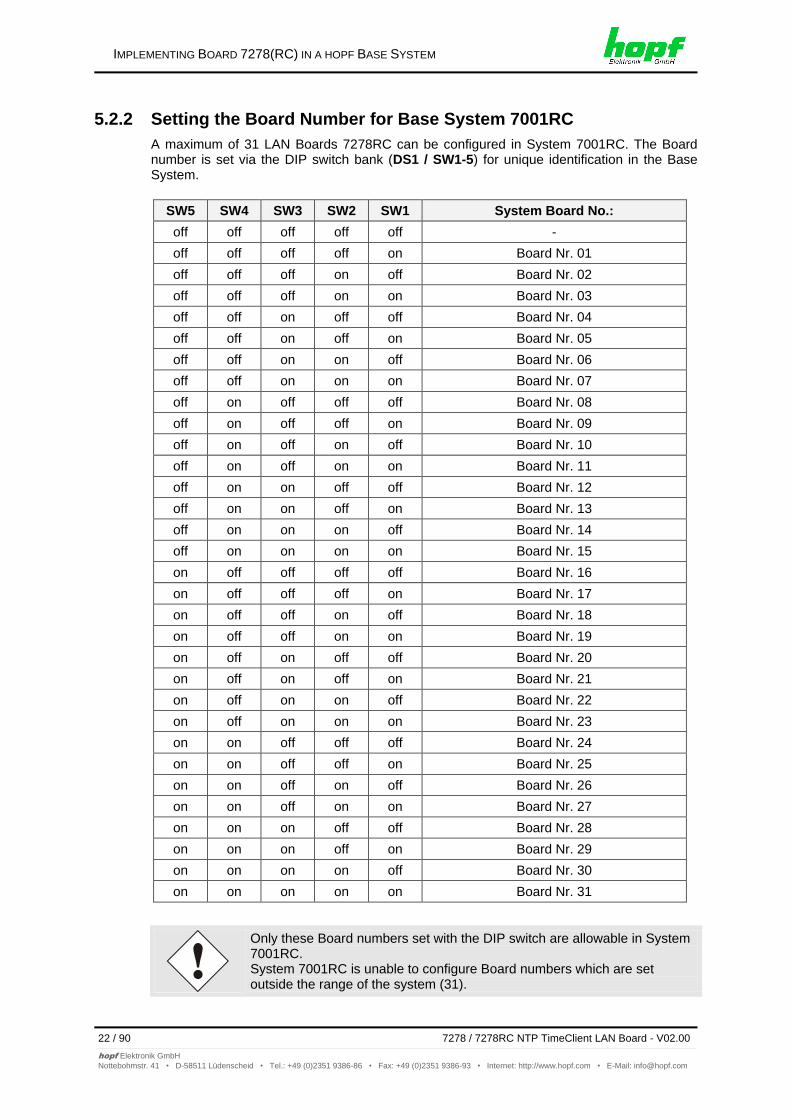
5.2.2 Setting the Board Number for Base System 7001RC
A maximum of 31 LAN Boards 7278RC can be configured in System 7001RC. The Board number is set via the DIP switch bank (DS1 / SW1-5) for unique identification in the Base System.
SW5 SW4 SW3 SW2 SW1 System Board No.:
off off off off off -
off off off off on Board Nr. 01
off off off on off Board Nr. 02
off off off on on Board Nr. 03
off off on off off Board Nr. 04
off off on off on Board Nr. 05
off off on on off Board Nr. 06
off off on on on Board Nr. 07
off on off off off Board Nr. 08
off on off off on Board Nr. 09
off on off on off Board Nr. 10
off on off on on Board Nr. 11
off on on off off Board Nr. 12
off on on off on Board Nr. 13
off on on on off Board Nr. 14
off on on on on Board Nr. 15
on off off off off Board Nr. 16
on off off off on Board Nr. 17
on off off on off Board Nr. 18
on off off on on Board Nr. 19
on off on off off Board Nr. 20
on off on off on Board Nr. 21
on off on on off Board Nr. 22
on off on on on Board Nr. 23
on on off off off Board Nr. 24
on on off off on Board Nr. 25
on on off on off Board Nr. 26
on on off on on Board Nr. 27
on on on off off Board Nr. 28
on on on off on Board Nr. 29
on on on on off Board Nr. 30
on on on on on Board Nr. 31
Only these Board numbers set with the DIP switch are allowable in System 7001RC. System 7001RC is unable to configure Board numbers which are set outside the range of the system (31).
IMPLEMENTING BOARD 7278(RC) IN A HOPF BASE SYSTEM
7278 / 7278RC NTP TimeClient LAN Board - V02.00 23 / 90
hopf Elektronik GmbH
Nottebohmstr. 41 • D-58511 Lüdenscheid • Tel.: +49 (0)2351 9386-86 • Fax: +49 (0)2351 9386-93 • Internet: http://www.hopf.com • E-Mail: [email protected]
5.2.3 Creating the Network Connection
Ensure that the network parameters of the LAN Board are configured in accordance with the local network before connecting the LAN Board to the network (see Chapter 6 Network Configuration for ETH0 via the Base System).
Connecting a network to an incorrectly configured LAN Board (e.g. duplicated IP address) may cause interference in the network.
Request the required network parameters from your network administrator if you do not know them.
The network connection is made via a LAN cable and RJ45 plug (recommended cable type: CAT5 or better).
NETWORK CONFIGURATION FOR ETH0 VIA THE BASE SYSTEM
24 / 90 7278 / 7278RC NTP TimeClient LAN Board - V02.00
hopf Elektronik GmbH
Nottebohmstr. 41 • D-58511 Lüdenscheid • Tel.: +49 (0)2351 9386-86 • Fax: +49 (0)2351 9386-93 • Internet: http://www.hopf.com • E-Mail: [email protected]
6 Network Configuration for ETH0 via the Base System The only configuration that is carried out on Board 7278(RC) via the Base System is to enable it to be reachable on the network via ETH0. All other configurations on the Board are carried out via the WebGUI.
LAN Board 7278(RC) is configured via the keyboard of the respective Base System. The necessary network parameters are configured such as IP address, gateway address, network mask and a general control byte.
The Technical Description of the respective Base System is the basis for configuration. The following covers only the Board-specific menus of the respective Base System.
After they have been entered fully, the LAN parameters configured through the system menu are transferred to the control board by pressing the ENT key. In order for the LAN parameters to be transferred from the
control board to the LAN Board and to be stored there it is necessary to exit the menu by pressing the BR key.
The Base System does not accept LAN parameters which are subsequently changed via the WebGUI and thus they are no longer displayed correctly. For this reason the assignment of LAN parameters via the Base System is recommended.
IP Address (IPv4)
An IP address is a 32 bit value divided into four 8 bit numbers. The standard presentation is 4 decimal numbers (in the range 0...255) separated from each other by dots (dotted quad notation).
Example: 192.002.001.123
The IP address consists of a leading network ID followed by the host ID. Four common network classes were defined in order to cover different requirements. Depending on the network class, the last one, two or three bytes define the host while the rest define the network (network ID) in each case.
In the following text the "x" stands for the host part of the IP address.
Class A Networks
IP addresses 001.xxx.xxx.xxx to 127.xxx.xxx.xxx
There is a maximum of 127 different networks in this class. This allows the possibility to connect a very high number of devices (max. 16.777.216 )
Example: 100.000.000.001, (Network 100, Host 000.000.001)
Class B Networks
IP addresses 128.000.xxx.xxx to 191.255.xxx.xxx
Each of these networks can consist of up to 65534 devices.
Example: 172.001.003.002 (Network 172.001, Host 003.002)
NETWORK CONFIGURATION FOR ETH0 VIA THE BASE SYSTEM
7278 / 7278RC NTP TimeClient LAN Board - V02.00 25 / 90
hopf Elektronik GmbH
Nottebohmstr. 41 • D-58511 Lüdenscheid • Tel.: +49 (0)2351 9386-86 • Fax: +49 (0)2351 9386-93 • Internet: http://www.hopf.com • E-Mail: [email protected]
Class C Networks
IP addresses 192.000.000.xx to 223.255.255.xxx
These network addresses are the most commonly used. Up to 254 devices can be connected.
Class D Networks
The addresses from 224.xxx.xxx.xxx - 239.xxx.xxx.xxx are used as multicast addresses.
Class E Networks
The addresses from 240.xxx.xxx.xxx - 254.xxx.xxx.xxx are designated as "Class E" and are reserved.
Gateway Address
The gateway or router address is required in order to be able to communicate with other network segments. The standard gateway must be set to the router address which connects these segments. This address must be within the local network.
Network Mask
The network mask is used to partition IP addresses outside of network classes A, B and C. When entering the network mask it is possible to designate the number of bits of the IP address to be used as the network part and the number to be used as the host part, e.g.:
Network Class
Network Part
Host Part
Network Mask Binary Network
Mask Decimal
A 8 Bit 24 Bit 11111111.00000000.00000000.00000000 255.0.0.0
B 16 Bit 16 Bit 11111111.11111111.00000000.00000000 255.255.0.0
C 24 Bit 8 Bit 11111111.11111111.11111111.00000000 255.255.255.0
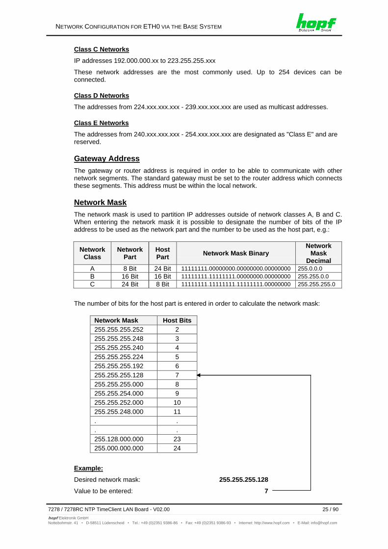
The number of bits for the host part is entered in order to calculate the network mask:
Network Mask Host Bits
255.255.255.252 2
255.255.255.248 3
255.255.255.240 4
255.255.255.224 5
255.255.255.192 6
255.255.255.128 7
255.255.255.000 8
255.255.254.000 9
255.255.252.000 10
255.255.248.000 11
. .
. .
255.128.000.000 23
255.000.000.000 24
Example:
Desired network mask: 255.255.255.128
Value to be entered: 7
NETWORK CONFIGURATION FOR ETH0 VIA THE BASE SYSTEM
26 / 90 7278 / 7278RC NTP TimeClient LAN Board - V02.00
hopf Elektronik GmbH
Nottebohmstr. 41 • D-58511 Lüdenscheid • Tel.: +49 (0)2351 9386-86 • Fax: +49 (0)2351 9386-93 • Internet: http://www.hopf.com • E-Mail: [email protected]
6.1 Input Functions of Base Systems 6842, 6850 and 6855
After they have been entered fully, the LAN parameters configured through the system menu are transferred to the control board by pressing the ENT key. In order for the LAN parameters to be transferred from the
control board to Board 7278RC it is necessary to exit the respective menu by pressing the BR key.
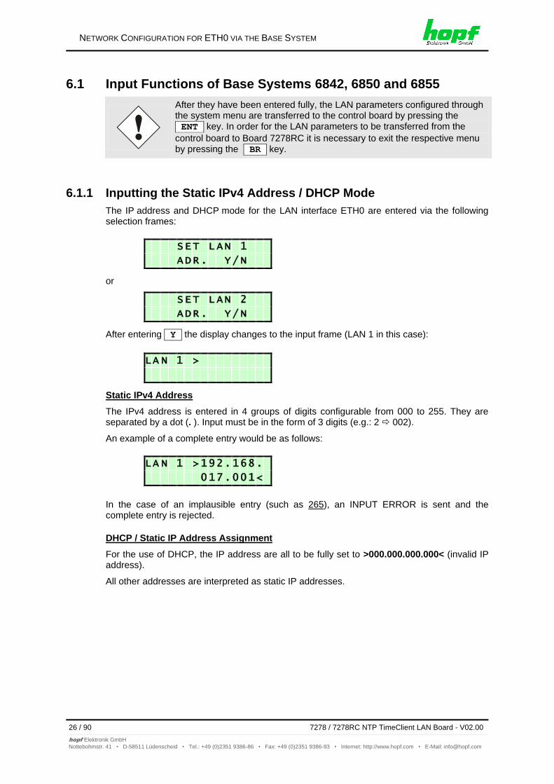
6.1.1 Inputting the Static IPv4 Address / DHCP Mode
The IP address and DHCP mode for the LAN interface ETH0 are entered via the following selection frames:
S E T L A N 1
A D R . Y / N
or
S E T L A N 2
A D R . Y / N
After entering Y the display changes to the input frame (LAN 1 in this case):
L A N 1 >
Static IPv4 Address
The IPv4 address is entered in 4 groups of digits configurable from 000 to 255. They are separated by a dot (. ). Input must be in the form of 3 digits (e.g.: 2 002).
An example of a complete entry would be as follows:
L A N 1 > 1 9 2 . 1 6 8 .
0 1 7 . 0 0 1 <
In the case of an implausible entry (such as 265), an INPUT ERROR is sent and the complete entry is rejected.
DHCP / Static IP Address Assignment
For the use of DHCP, the IP address are all to be fully set to >000.000.000.000< (invalid IP address).
All other addresses are interpreted as static IP addresses.
NETWORK CONFIGURATION FOR ETH0 VIA THE BASE SYSTEM
7278 / 7278RC NTP TimeClient LAN Board - V02.00 27 / 90
hopf Elektronik GmbH
Nottebohmstr. 41 • D-58511 Lüdenscheid • Tel.: +49 (0)2351 9386-86 • Fax: +49 (0)2351 9386-93 • Internet: http://www.hopf.com • E-Mail: [email protected]
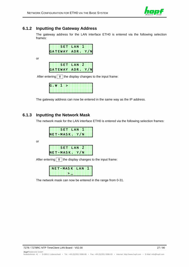
6.1.2 Inputting the Gateway Address
The gateway address for the LAN interface ETH0 is entered via the following selection frames:
S E T L A N 1
G A T E W A Y A D R . Y / N
or
S E T L A N 2
G A T E W A Y A D R . Y / N
After entering Y the display changes to the input frame:
G . W 1 >
The gateway address can now be entered in the same way as the IP address.
6.1.3 Inputting the Network Mask
The network mask for the LAN interface ETH0 is entered via the following selection frames:
S E T L A N 1
N E T - M A S K . Y / N
or
S E T L A N 2
N E T - M A S K . Y / N
After entering Y the display changes to the input frame:
N E T - M A S K L A N 1
> _
The network mask can now be entered in the range from 0-31.
NETWORK CONFIGURATION FOR ETH0 VIA THE BASE SYSTEM
28 / 90 7278 / 7278RC NTP TimeClient LAN Board - V02.00
hopf Elektronik GmbH
Nottebohmstr. 41 • D-58511 Lüdenscheid • Tel.: +49 (0)2351 9386-86 • Fax: +49 (0)2351 9386-93 • Internet: http://www.hopf.com • E-Mail: [email protected]
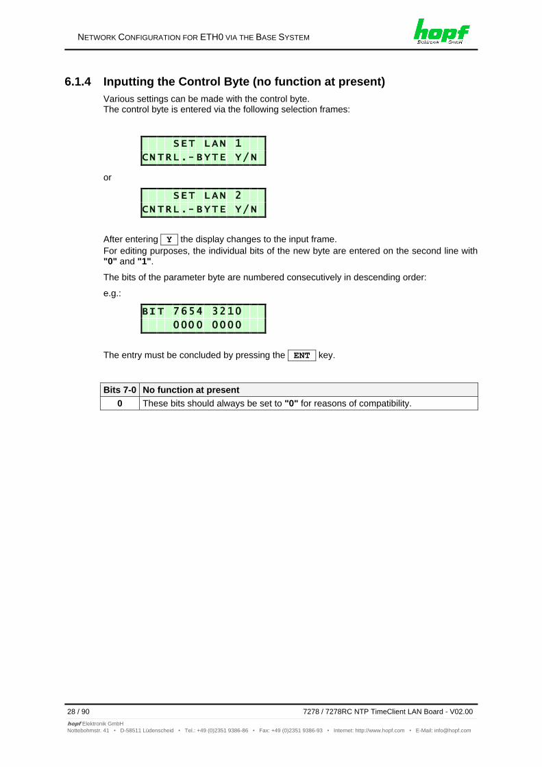
6.1.4 Inputting the Control Byte (no function at present)
Various settings can be made with the control byte. The control byte is entered via the following selection frames:
S E T L A N 1
C N T R L . - B Y T E Y / N
or
S E T L A N 2
C N T R L . - B Y T E Y / N
After entering Y the display changes to the input frame.
For editing purposes, the individual bits of the new byte are entered on the second line with "0" and "1".
The bits of the parameter byte are numbered consecutively in descending order:
e.g.:
B I T 7 6 5 4 3 2 1 0
0 0 0 0 0 0 0 0
The entry must be concluded by pressing the ENT key.
Bits 7-0 No function at present
0 These bits should always be set to "0" for reasons of compatibility.
NETWORK CONFIGURATION FOR ETH0 VIA THE BASE SYSTEM
7278 / 7278RC NTP TimeClient LAN Board - V02.00 29 / 90
hopf Elektronik GmbH
Nottebohmstr. 41 • D-58511 Lüdenscheid • Tel.: +49 (0)2351 9386-86 • Fax: +49 (0)2351 9386-93 • Internet: http://www.hopf.com • E-Mail: [email protected]
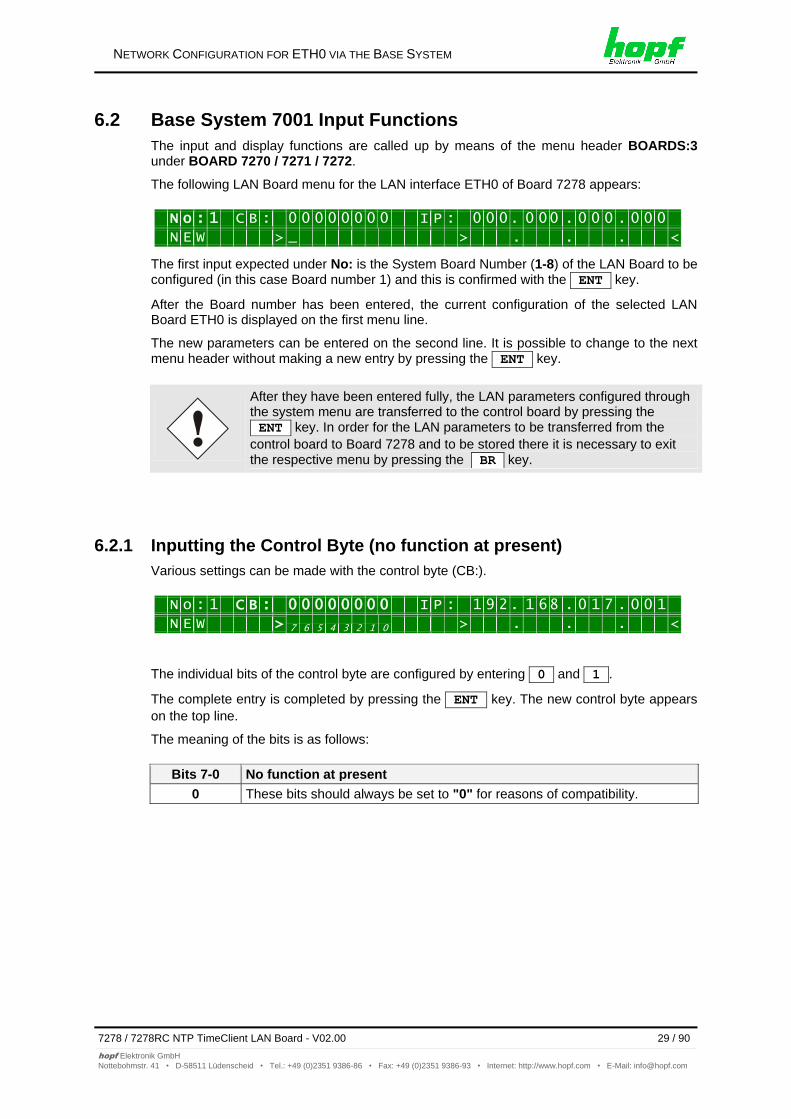
6.2 Base System 7001 Input Functions
The input and display functions are called up by means of the menu header BOARDS:3 under BOARD 7270 / 7271 / 7272.
The following LAN Board menu for the LAN interface ETH0 of Board 7278 appears:
N o : 1 C B : 0 0 0 0 0 0 0 0 I P : 0 0 0 . 0 0 0 . 0 0 0 . 0 0 0
N E W > _ > . . . <
The first input expected under No: is the System Board Number (1-8) of the LAN Board to be configured (in this case Board number 1) and this is confirmed with the ENT key.
After the Board number has been entered, the current configuration of the selected LAN Board ETH0 is displayed on the first menu line.
The new parameters can be entered on the second line. It is possible to change to the next menu header without making a new entry by pressing the ENT key.
After they have been entered fully, the LAN parameters configured through the system menu are transferred to the control board by pressing the ENT key. In order for the LAN parameters to be transferred from the
control board to Board 7278 and to be stored there it is necessary to exit the respective menu by pressing the BR key.
6.2.1 Inputting the Control Byte (no function at present)
Various settings can be made with the control byte (CB:).
N o : 1 C B : 0 0 0 0 0 0 0 0 I P : 1 9 2 . 1 6 8 . 0 1 7 . 0 0 1
N E W > 7 6 5 4 3 2 1 0 > . . . <
The individual bits of the control byte are configured by entering 0 and 1 .
The complete entry is completed by pressing the ENT key. The new control byte appears
on the top line.
The meaning of the bits is as follows:
Bits 7-0 No function at present
0 These bits should always be set to "0" for reasons of compatibility.
NETWORK CONFIGURATION FOR ETH0 VIA THE BASE SYSTEM
30 / 90 7278 / 7278RC NTP TimeClient LAN Board - V02.00
hopf Elektronik GmbH
Nottebohmstr. 41 • D-58511 Lüdenscheid • Tel.: +49 (0)2351 9386-86 • Fax: +49 (0)2351 9386-93 • Internet: http://www.hopf.com • E-Mail: [email protected]
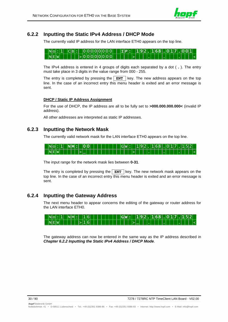
6.2.2 Inputting the Static IPv4 Address / DHCP Mode
The currently valid IP address for the LAN interface ETH0 appears on the top line.
N o : 1 C B : 0 0 0 0 0 0 0 0 I P : 1 9 2 . 1 6 8 . 0 1 7 . 0 0 1
N E W > 0 0 0 0 0 0 0 0 > . . . <
The IPv4 address is entered in 4 groups of digits each separated by a dot ( . ). The entry must take place in 3 digits in the value range from 000 - 255.
The entry is completed by pressing the ENT key. The new address appears on the top
line. In the case of an incorrect entry this menu header is exited and an error message is sent.
DHCP / Static IP Address Assignment
For the use of DHCP, the IP address are all to be fully set to >000.000.000.000< (invalid IP address).
All other addresses are interpreted as static IP addresses.
6.2.3 Inputting the Network Mask
The currently valid network mask for the LAN interface ETH0 appears on the top line.
N o : 1 N M : 0 0 G W : 1 9 2 . 1 6 8 . 0 1 7 . 1 5 2
N E W > _ > . . . <
The input range for the network mask lies between 0-31.
The entry is completed by pressing the ENT key. The new network mask appears on the
top line. In the case of an incorrect entry this menu header is exited and an error message is sent.
6.2.4 Inputting the Gateway Address
The next menu header to appear concerns the editing of the gateway or router address for the LAN interface ETH0.
N o : 1 N M : 1 6 G W : 1 9 2 . 1 6 8 . 0 1 7 . 1 5 2
N E W > 1 6 > _ . . . <
The gateway address can now be entered in the same way as the IP address described in Chapter 6.2.2 Inputting the Static IPv4 Address / DHCP Mode.
NETWORK CONFIGURATION FOR ETH0 VIA THE BASE SYSTEM
7278 / 7278RC NTP TimeClient LAN Board - V02.00 31 / 90
hopf Elektronik GmbH
Nottebohmstr. 41 • D-58511 Lüdenscheid • Tel.: +49 (0)2351 9386-86 • Fax: +49 (0)2351 9386-93 • Internet: http://www.hopf.com • E-Mail: [email protected]
6.3 Input Functions of Base Systems 7001RC
After they have been entered fully, the LAN parameters configured through the system menu are transferred to the control board by pressing the ENT key. From here the parameters are transferred to the LAN board.
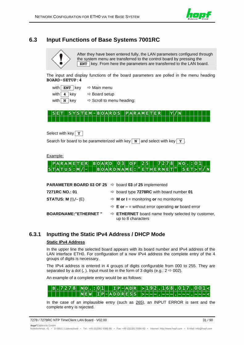
The input and display functions of the board parameters are polled in the menu heading BOARD-SETUP:4
with ENT key Main menu
with 4 key Board setup
with N key Scroll to menu heading:
S E T S Y S T E M - B O A R D S P A R A M E T E R Y / N
Select with key Y
Search for board to be parameterized with key N and select with key Y .
Example:
P A R A M E T E R B O A R D 0 3 O F 2 5 7 2 7 8 N O . : 0 1
S T A T U S : M / - B O A R D N A M E : " E T H E R N E T " S E T > Y /N N
PARAMETER BOARD 03 OF 25 board 03 of 25 implemented
7271RC NO.: 01 board type 7278RC with board number 01
STATUS: M (I)/- (E) M or I = monitoring or no monitoring
E or – = without error operating or board error
BOARDNAME:"ETHERNET " ETHERNET board name freely selected by customer, up to 8 characters
6.3.1 Inputting the Static IPv4 Address / DHCP Mode
Static IPv4 Address
In the upper line the selected board appears with its board number and IPv4 address of the LAN interface ETH0. For configuration of a new IPv4 address the complete entry of the 4 groups of digits is necessary.
The IPv4 address is entered in 4 groups of digits configurable from 000 to 255. They are separated by a dot (. ). Input must be in the form of 3 digits (e.g.: 2 002).
An example of a complete entry would be as follows:
B . 7 2 7 8 N O . : 0 1 I P - A D R > 1 9 2 . 1 6 8 . 0 1 7 . 0 0 1 <
N E W I P - A D D R E S S > ~ ~ ~ . ~ ~ ~ . ~ ~ ~ . ~ ~ ~ <
In the case of an implausible entry (such as 265), an INPUT ERROR is sent and the complete entry is rejected.
NETWORK CONFIGURATION FOR ETH0 VIA THE BASE SYSTEM
32 / 90 7278 / 7278RC NTP TimeClient LAN Board - V02.00
hopf Elektronik GmbH
Nottebohmstr. 41 • D-58511 Lüdenscheid • Tel.: +49 (0)2351 9386-86 • Fax: +49 (0)2351 9386-93 • Internet: http://www.hopf.com • E-Mail: [email protected]
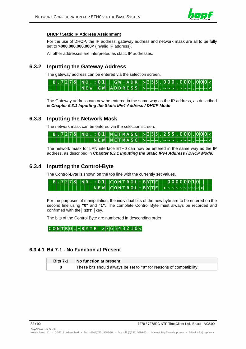
DHCP / Static IP Address Assignment
For the use of DHCP, the IP address, gateway address and network mask are all to be fully set to >000.000.000.000< (invalid IP address).
All other addresses are interpreted as static IP addresses.
6.3.2 Inputting the Gateway Address
The gateway address can be entered via the selection screen.
B . 7 2 7 8 N O . : 0 1 G W - A D R > 2 5 5 . 0 0 0 . 0 0 0 . 0 0 0 < N E W G W - A D D R E S S > ~ ~ ~ . ~ ~ ~ . ~ ~ ~ . ~ ~ ~ <
The Gateway address can now be entered in the same way as the IP address, as described in Chapter 6.3.1 Inputting the Static IPv4 Address / DHCP Mode.
6.3.3 Inputting the Network Mask
The network mask can be entered via the selection screen.
B . 7 2 7 8 N O . : 0 1 N E T M A S C > 2 5 5 . 2 5 5 . 0 0 0 . 0 0 0 <
N E W N E T M A S C > ~ ~ ~ . ~ ~ ~ . ~ ~ ~ . ~ ~ ~ <
The network mask for LAN interface ETH0 can now be entered in the same way as the IP address, as described in Chapter 6.3.1 Inputting the Static IPv4 Address / DHCP Mode.
6.3.4 Inputting the Control-Byte
The Control-Byte is shown on the top line with the currently set values.
B . 7 2 7 8 N R . : 0 1 C O N T R O L - B Y T E 0 0 0 0 0 0 1 0
N E W C O N T R O L - B Y T E > ~ ~ ~ ~ ~ ~ ~ ~ <
For the purposes of manipulation, the individual bits of the new byte are to be entered on the second line using "0" and "1". The complete Control Byte must always be recorded and confirmed with the ENT key.
The bits of the Control Byte are numbered in descending order:
C O N T R O L - B Y T E > 7 6 5 4 3 2 1 0 <
6.3.4.1 Bit 7-1 - No Function at Present
Bits 7-1 No function at present
0 These bits should always be set to "0" for reasons of compatibility.
NETWORK CONFIGURATION FOR ETH0 VIA THE BASE SYSTEM
7278 / 7278RC NTP TimeClient LAN Board - V02.00 33 / 90
hopf Elektronik GmbH
Nottebohmstr. 41 • D-58511 Lüdenscheid • Tel.: +49 (0)2351 9386-86 • Fax: +49 (0)2351 9386-93 • Internet: http://www.hopf.com • E-Mail: [email protected]
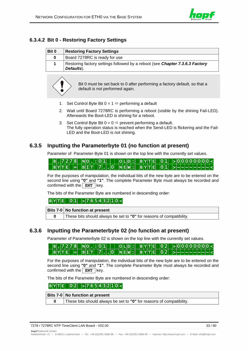
6.3.4.2 Bit 0 - Restoring Factory Settings
Bit 0 Restoring Factory Settings
0 Board 7278RC is ready for use
1 Restoring factory settings followed by a reboot (see Chapter 7.3.6.3 Factory Defaults).
Bit 0 must be set back to 0 after performing a factory default, so that a default is not performed again.
1. Set Control Byte Bit 0 = 1 performing a default
2. Wait until Board 7278RC is performing a reboot (visible by the shining Fail-LED). Afterwards the Boot-LED is shining for a reboot.
3. Set Control Byte Bit 0 = 0 prevent performing a default. The fully operation status is reached when the Send-LED is flickering and the Fail-LED and the Boot-LED is not shining.
6.3.5 Inputting the Parameterbyte 01 (no function at present)
Parameter of Parameter-Byte 01 is shown on the top line with the currently set values.
B . 7 2 7 8 N O . : 0 1 O L D : B Y T E 0 1 > 0 0 0 0 0 0 0 0 <
B Y T E = B I T 7 . . 0 N E W : B Y T E 0 1 > ~ ~ ~ ~ ~ ~ ~ ~ <
For the purposes of manipulation, the individual bits of the new byte are to be entered on the second line using "0" and "1". The complete Parameter Byte must always be recorded and confirmed with the ENT key.
The bits of the Parameter Byte are numbered in descending order:
B Y T E 0 1 > 7 6 5 4 3 2 1 0 <
Bits 7-0 No function at present
0 These bits should always be set to "0" for reasons of compatibility.
6.3.6 Inputting the Parameterbyte 02 (no function at present)
Parameter of Parameterbyte 02 is shown on the top line with the currently set values.
B . 7 2 7 8 N O . : 0 1 O L D : B Y T E 0 2 > 0 0 0 0 0 0 0 0 <
B Y T E = B I T 7 . . 0 N E W : B Y T E 0 2 > ~ ~ ~ ~ ~ ~ ~ ~ <
For the purposes of manipulation, the individual bits of the new byte are to be entered on the second line using "0" and "1". The complete Parameter Byte must always be recorded and confirmed with the ENT key.
The bits of the Parameter Byte are numbered in descending order:
B Y T E 0 2 > 7 6 5 4 3 2 1 0 <
Bits 7-0 No function at present
0 These bits should always be set to "0" for reasons of compatibility.
NETWORK CONFIGURATION FOR ETH0 VIA THE BASE SYSTEM
34 / 90 7278 / 7278RC NTP TimeClient LAN Board - V02.00
hopf Elektronik GmbH
Nottebohmstr. 41 • D-58511 Lüdenscheid • Tel.: +49 (0)2351 9386-86 • Fax: +49 (0)2351 9386-93 • Internet: http://www.hopf.com • E-Mail: [email protected]
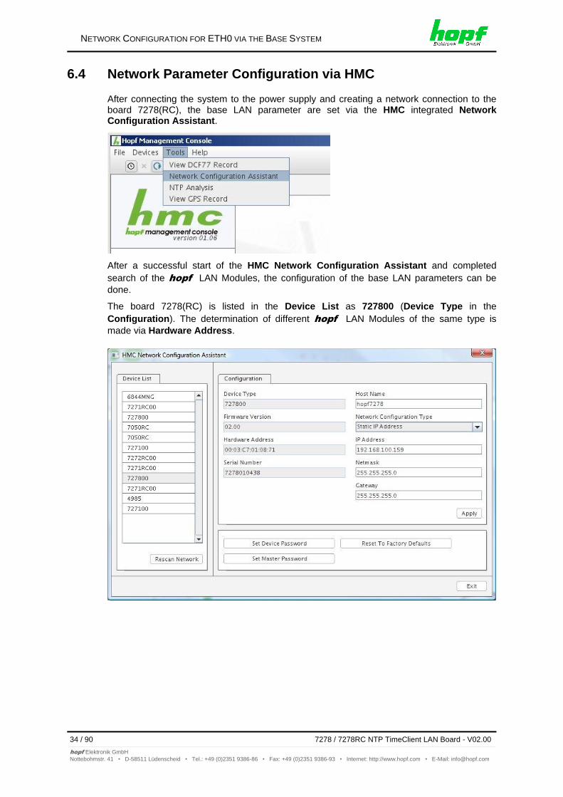
6.4 Network Parameter Configuration via HMC
After connecting the system to the power supply and creating a network connection to the board 7278(RC), the base LAN parameter are set via the HMC integrated Network Configuration Assistant.
After a successful start of the HMC Network Configuration Assistant and completed
search of the hopf LAN Modules, the configuration of the base LAN parameters can be
done.
The board 7278(RC) is listed in the Device List as 727800 (Device Type in the
Configuration). The determination of different hopf LAN Modules of the same type is
made via Hardware Address.
NETWORK CONFIGURATION FOR ETH0 VIA THE BASE SYSTEM
7278 / 7278RC NTP TimeClient LAN Board - V02.00 35 / 90
hopf Elektronik GmbH
Nottebohmstr. 41 • D-58511 Lüdenscheid • Tel.: +49 (0)2351 9386-86 • Fax: +49 (0)2351 9386-93 • Internet: http://www.hopf.com • E-Mail: [email protected]
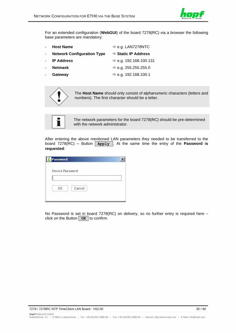
For an extended configuration (WebGUI) of the board 7278(RC) via a browser the following base parameters are mandatory:
- Host Name e.g. LAN7278NTC
- Network Configuration Type Static IP Address
- IP Address e.g. 192.168.100.131
- Netmask e.g. 255.255.255.0
- Gateway e.g. 192.168.100.1
The Host Name should only consist of alphanumeric characters (letters and numbers). The first character should be a letter.
The network parameters for the board 7278(RC) should be pre-determined with the network administrator.
After entering the above mentioned LAN parameters they needed to be transferred to the board 7278(RC) – Button Apply . At the same time the entry of the Password is
requested:
No Password is set in board 7278(RC) on delivery, so no further entry is required here – click on the Button OK to confirm.
HTTP/HTTPS WEBGUI – WEB BROWSER CONFIGURATION INTERFACE
36 / 90 7278 / 7278RC NTP TimeClient LAN Board - V02.00
hopf Elektronik GmbH
Nottebohmstr. 41 • D-58511 Lüdenscheid • Tel.: +49 (0)2351 9386-86 • Fax: +49 (0)2351 9386-93 • Internet: http://www.hopf.com • E-Mail: [email protected]
7 HTTP/HTTPS WebGUI – Web Browser Configuration Interface
JavaScript and Cookies must be enabled in the browser in order for the WebGUI to display and function correctly.
The WebGUI has been tested with the following browsers: MOZILLA 1.x, Netscape 7.x and IE 6.x – some functions do not run on older versions.
7.1 Quick Configuration
This Chapter briefly describes the basic operation of the WebGUI installed on the Board.
7.1.1 Requirements
Ready-for-operation hopf Base System with implemented Board 7278(RC)
Board configured for network operation (see Chapter 6 Network Configuration for ETH0 via the Base System)
PC with installed web browser (e.g. Internet Explorer) in the sub-network of Board 7278(RC)
7.1.2 Configuration Steps
Create the connection to the Board with a web browser
Login as a 'master' user (no password is set initially)
Switch to "Network" tab and enter the DNS Server (required for NTP and the alarm)
Save the configuration
Switch to "Device" tab and restart Network Time Server via "Reboot Device"
NTP Service is now available with the standard settings
The following detailed explanatory information should be read if anything is unclear while executing the configuration steps.
HTTP/HTTPS WEBGUI – WEB BROWSER CONFIGURATION INTERFACE
7278 / 7278RC NTP TimeClient LAN Board - V02.00 37 / 90
hopf Elektronik GmbH
Nottebohmstr. 41 • D-58511 Lüdenscheid • Tel.: +49 (0)2351 9386-86 • Fax: +49 (0)2351 9386-93 • Internet: http://www.hopf.com • E-Mail: [email protected]
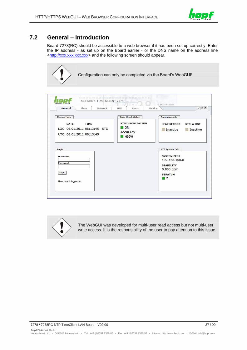
7.2 General – Introduction
Board 7278(RC) should be accessible to a web browser if it has been set up correctly. Enter the IP address - as set up on the Board earlier - or the DNS name on the address line <http://xxx.xxx.xxx.xxx> and the following screen should appear.
Configuration can only be completed via the Board’s WebGUI!
The WebGUI was developed for multi-user read access but not multi-user write access. It is the responsibility of the user to pay attention to this issue.
HTTP/HTTPS WEBGUI – WEB BROWSER CONFIGURATION INTERFACE
38 / 90 7278 / 7278RC NTP TimeClient LAN Board - V02.00
hopf Elektronik GmbH
Nottebohmstr. 41 • D-58511 Lüdenscheid • Tel.: +49 (0)2351 9386-86 • Fax: +49 (0)2351 9386-93 • Internet: http://www.hopf.com • E-Mail: [email protected]
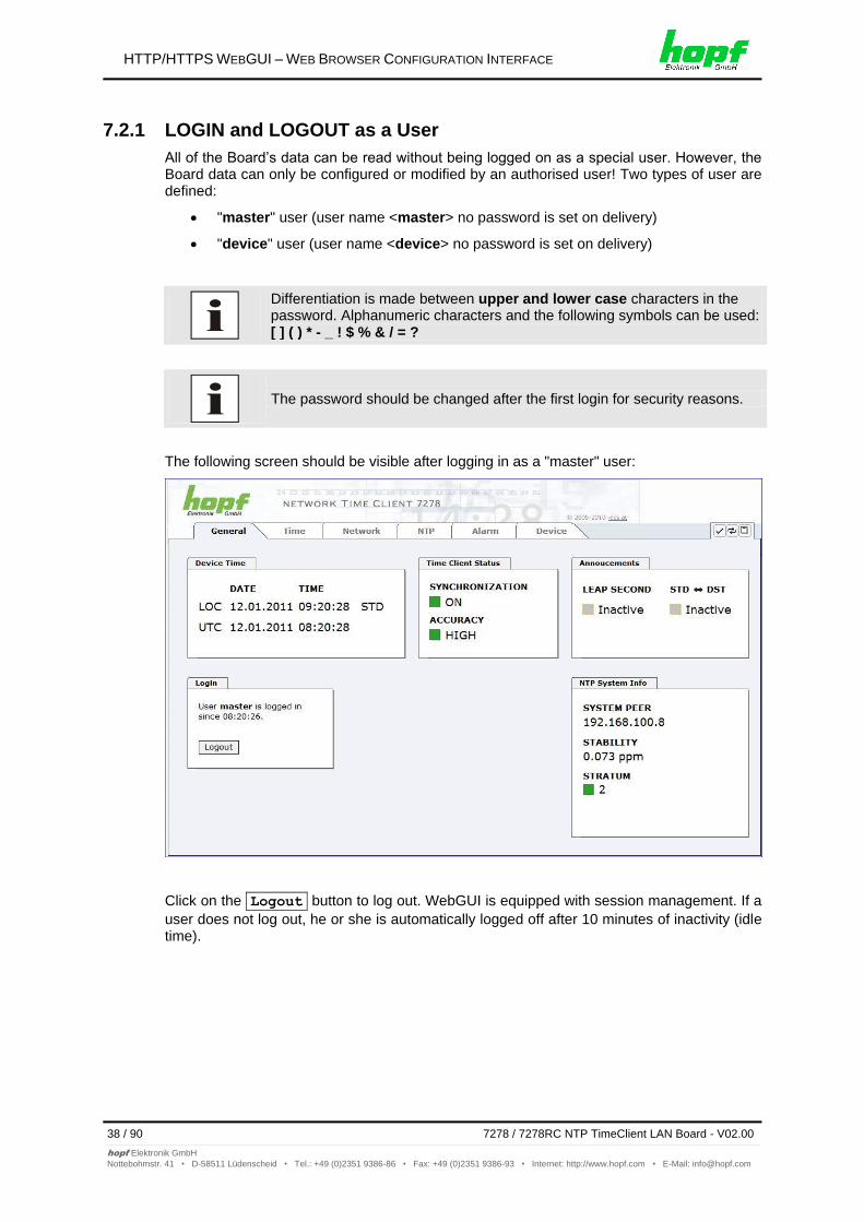
7.2.1 LOGIN and LOGOUT as a User
All of the Board’s data can be read without being logged on as a special user. However, the Board data can only be configured or modified by an authorised user! Two types of user are defined:
"master" user (user name <master> no password is set on delivery)
"device" user (user name <device> no password is set on delivery)
Differentiation is made between upper and lower case characters in the password. Alphanumeric characters and the following symbols can be used: [ ] ( ) * - _ ! $ % & / = ?
The password should be changed after the first login for security reasons.
The following screen should be visible after logging in as a "master" user:
Click on the Logout button to log out. WebGUI is equipped with session management. If a
user does not log out, he or she is automatically logged off after 10 minutes of inactivity (idle time).
HTTP/HTTPS WEBGUI – WEB BROWSER CONFIGURATION INTERFACE
7278 / 7278RC NTP TimeClient LAN Board - V02.00 39 / 90
hopf Elektronik GmbH
Nottebohmstr. 41 • D-58511 Lüdenscheid • Tel.: +49 (0)2351 9386-86 • Fax: +49 (0)2351 9386-93 • Internet: http://www.hopf.com • E-Mail: [email protected]
After successful login, depending on the access level (device or master user), changes can be made to the configuration and saved.
Users logged in as Master have all access rights to Board 7278(RC).
Users logged in as Device do not have access to:
Trigger reboot
Trigger factory defaults
Carry out image update
Carry out H8 firmware update
Upload certification
Change master password
Download configuration files
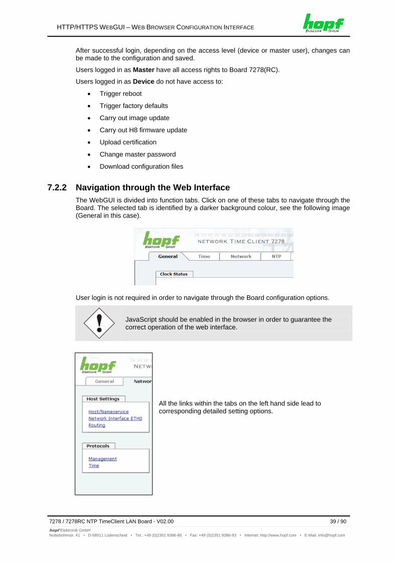
7.2.2 Navigation through the Web Interface
The WebGUI is divided into function tabs. Click on one of these tabs to navigate through the Board. The selected tab is identified by a darker background colour, see the following image (General in this case).
User login is not required in order to navigate through the Board configuration options.
JavaScript should be enabled in the browser in order to guarantee the correct operation of the web interface.
All the links within the tabs on the left hand side lead to corresponding detailed setting options.
HTTP/HTTPS WEBGUI – WEB BROWSER CONFIGURATION INTERFACE
40 / 90 7278 / 7278RC NTP TimeClient LAN Board - V02.00
hopf Elektronik GmbH
Nottebohmstr. 41 • D-58511 Lüdenscheid • Tel.: +49 (0)2351 9386-86 • Fax: +49 (0)2351 9386-93 • Internet: http://www.hopf.com • E-Mail: [email protected]
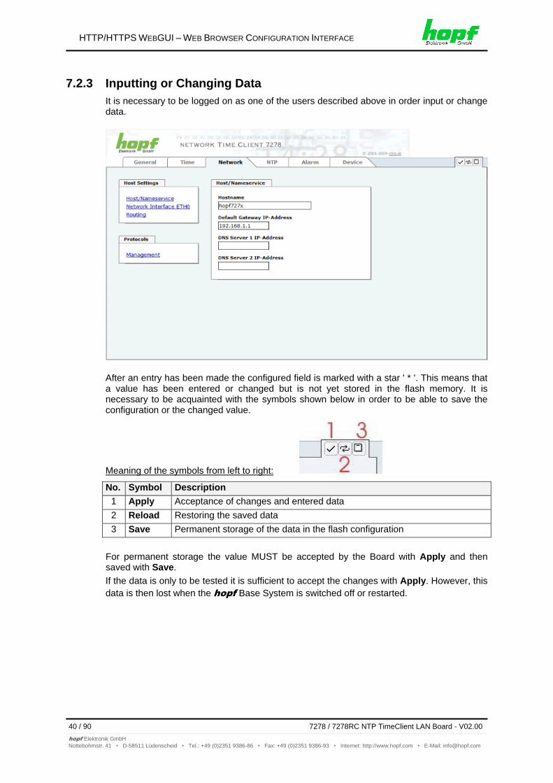
7.2.3 Inputting or Changing Data
It is necessary to be logged on as one of the users described above in order input or change data.
After an entry has been made the configured field is marked with a star ' * '. This means that a value has been entered or changed but is not yet stored in the flash memory. It is necessary to be acquainted with the symbols shown below in order to be able to save the configuration or the changed value.
Meaning of the symbols from left to right:
No. Symbol Description
1 Apply Acceptance of changes and entered data
2 Reload Restoring the saved data
3 Save Permanent storage of the data in the flash configuration
For permanent storage the value MUST be accepted by the Board with Apply and then saved with Save.
If the data is only to be tested it is sufficient to accept the changes with Apply. However, this
data is then lost when the hopf Base System is switched off or restarted.
HTTP/HTTPS WEBGUI – WEB BROWSER CONFIGURATION INTERFACE
7278 / 7278RC NTP TimeClient LAN Board - V02.00 41 / 90
hopf Elektronik GmbH
Nottebohmstr. 41 • D-58511 Lüdenscheid • Tel.: +49 (0)2351 9386-86 • Fax: +49 (0)2351 9386-93 • Internet: http://www.hopf.com • E-Mail: [email protected]
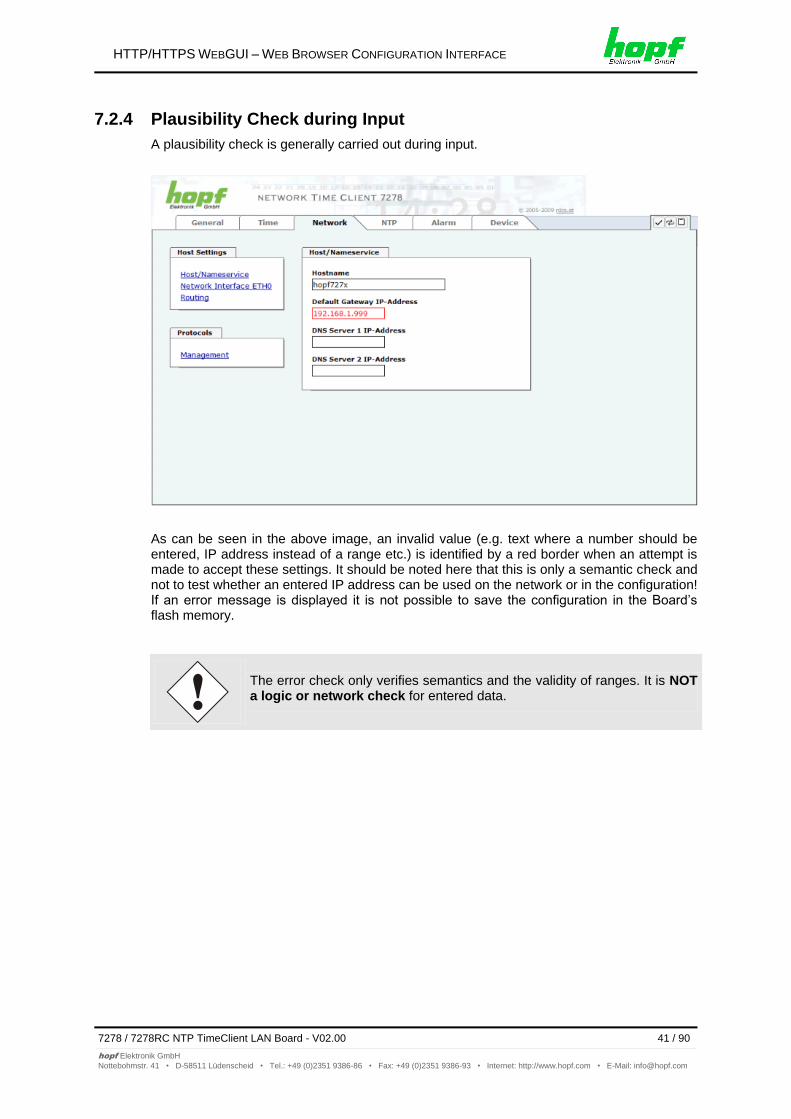
7.2.4 Plausibility Check during Input
A plausibility check is generally carried out during input.
As can be seen in the above image, an invalid value (e.g. text where a number should be entered, IP address instead of a range etc.) is identified by a red border when an attempt is made to accept these settings. It should be noted here that this is only a semantic check and not to test whether an entered IP address can be used on the network or in the configuration! If an error message is displayed it is not possible to save the configuration in the Board’s flash memory.
The error check only verifies semantics and the validity of ranges. It is NOT a logic or network check for entered data.
HTTP/HTTPS WEBGUI – WEB BROWSER CONFIGURATION INTERFACE
42 / 90 7278 / 7278RC NTP TimeClient LAN Board - V02.00
hopf Elektronik GmbH
Nottebohmstr. 41 • D-58511 Lüdenscheid • Tel.: +49 (0)2351 9386-86 • Fax: +49 (0)2351 9386-93 • Internet: http://www.hopf.com • E-Mail: [email protected]
7.3 Description of the Tabs
The WebGUI is divided into the following tabs:
General
Time
Network
NTP
Alarm
Device
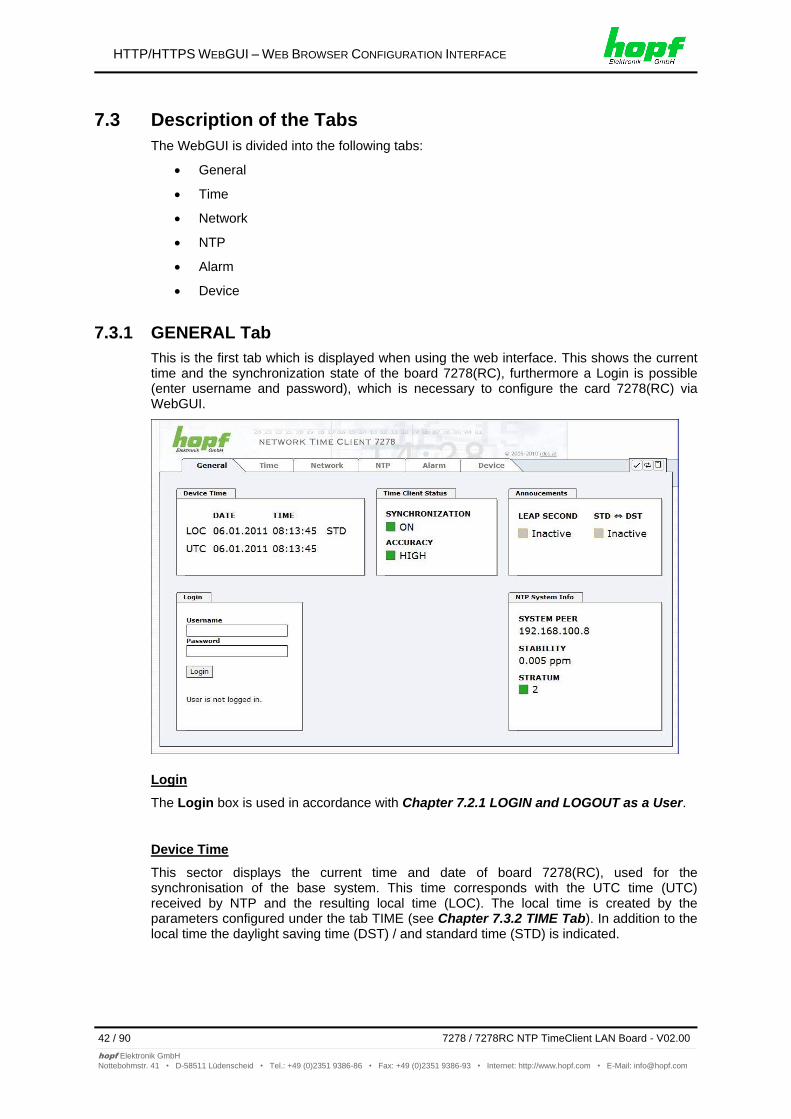
7.3.1 GENERAL Tab
This is the first tab which is displayed when using the web interface. This shows the current time and the synchronization state of the board 7278(RC), furthermore a Login is possible (enter username and password), which is necessary to configure the card 7278(RC) via WebGUI.
Login
The Login box is used in accordance with Chapter 7.2.1 LOGIN and LOGOUT as a User.
Device Time
This sector displays the current time and date of board 7278(RC), used for the synchronisation of the base system. This time corresponds with the UTC time (UTC) received by NTP and the resulting local time (LOC). The local time is created by the parameters configured under the tab TIME (see Chapter 7.3.2 TIME Tab). In addition to the local time the daylight saving time (DST) / and standard time (STD) is indicated.
HTTP/HTTPS WEBGUI – WEB BROWSER CONFIGURATION INTERFACE
7278 / 7278RC NTP TimeClient LAN Board - V02.00 43 / 90
hopf Elektronik GmbH
Nottebohmstr. 41 • D-58511 Lüdenscheid • Tel.: +49 (0)2351 9386-86 • Fax: +49 (0)2351 9386-93 • Internet: http://www.hopf.com • E-Mail: [email protected]
Time Client Status
SYNCHRONIZATION indicates the synchronisation status of the base System.
ON: Base System is synchronized
OFF: Base System is not synchronized
The ACCURACY field (accuracy of NTP) can include the possible values LOW - MEDIUM - HIGH. The meaning of those values is explained in Chapter 11.6 Accuracy & NTP Basic Principles.
Announcements
LEAP SECOND announcement for inserting a leap second
Inactive: No announcement exists
Active: There is an announcement. A leap second is inserted on the next hour.
STD DST Announcement for adjustment for daylight saving time / standard time
Inactive: No announcement exists
Active: There is an announcement. An adjustment for daylight saving time / standard time is made on the next hour.
NTP System Info
SYSTEM PEER indicates the currently used NTP-System-peer for the synchronisation.
STABILITY indicates the current NTP stability value of board 7278(RC) in ppm.
STRATUM indicates the current NTP stratum value of board 7278(RC) in the vale range of 1-16.
HTTP/HTTPS WEBGUI – WEB BROWSER CONFIGURATION INTERFACE
44 / 90 7278 / 7278RC NTP TimeClient LAN Board - V02.00
hopf Elektronik GmbH
Nottebohmstr. 41 • D-58511 Lüdenscheid • Tel.: +49 (0)2351 9386-86 • Fax: +49 (0)2351 9386-93 • Internet: http://www.hopf.com • E-Mail: [email protected]
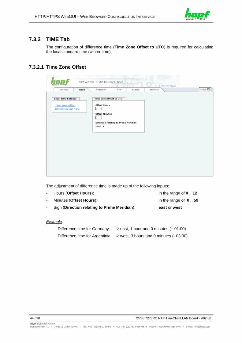
7.3.2 TIME Tab
The configuration of difference time (Time Zone Offset to UTC) is required for calculating the local standard time (winter time).
7.3.2.1 Time Zone Offset
The adjustment of difference time is made up of the following inputs:
- Hours (Offset Hours): in the range of 0 .. 12
- Minutes (Offset Hours): in the range of 0 .. 59
- Sign (Direction relating to Prime Meridian): east or west
Example:
Difference time for Germany east, 1 hour and 0 minutes (+ 01:00)
Difference time for Argentinia west, 3 hours and 0 minutes (- 03:00)
HTTP/HTTPS WEBGUI – WEB BROWSER CONFIGURATION INTERFACE
7278 / 7278RC NTP TimeClient LAN Board - V02.00 45 / 90
hopf Elektronik GmbH
Nottebohmstr. 41 • D-58511 Lüdenscheid • Tel.: +49 (0)2351 9386-86 • Fax: +49 (0)2351 9386-93 • Internet: http://www.hopf.com • E-Mail: [email protected]
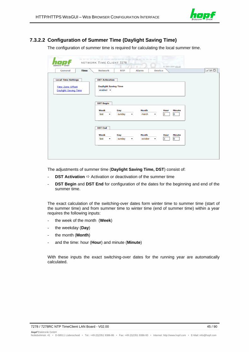
7.3.2.2 Configuration of Summer Time (Daylight Saving Time)
The configuration of summer time is required for calculating the local summer time.
The adjustments of summer time (Daylight Saving Time, DST) consist of:
- DST Activation Activation or deactivation of the summer time
- DST Begin and DST End for configuration of the dates for the beginning and end of the summer time.
The exact calculation of the switching-over dates form winter time to summer time (start of the summer time) and from summer time to winter time (end of summer time) within a year requires the following inputs:
- the week of the month (Week)
- the weekday (Day)
- the month (Month)
- and the time: hour (Hour) and minute (Minute)
With these inputs the exact switching-over dates for the running year are automatically calculated.
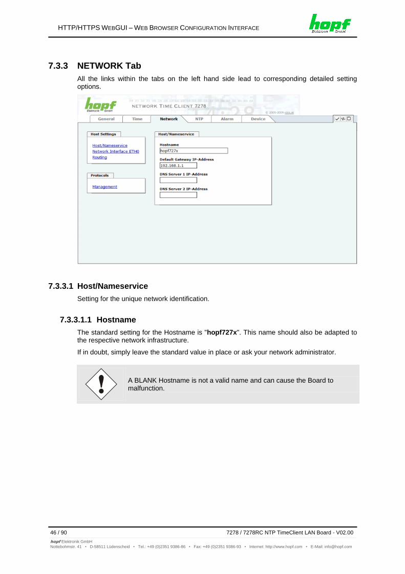
HTTP/HTTPS WEBGUI – WEB BROWSER CONFIGURATION INTERFACE
46 / 90 7278 / 7278RC NTP TimeClient LAN Board - V02.00
hopf Elektronik GmbH
Nottebohmstr. 41 • D-58511 Lüdenscheid • Tel.: +49 (0)2351 9386-86 • Fax: +49 (0)2351 9386-93 • Internet: http://www.hopf.com • E-Mail: [email protected]
7.3.3 NETWORK Tab
All the links within the tabs on the left hand side lead to corresponding detailed setting options.
7.3.3.1 Host/Nameservice
Setting for the unique network identification.
7.3.3.1.1 Hostname
The standard setting for the Hostname is "hopf727x". This name should also be adapted to the respective network infrastructure.
If in doubt, simply leave the standard value in place or ask your network administrator.
A BLANK Hostname is not a valid name and can cause the Board to malfunction.
HTTP/HTTPS WEBGUI – WEB BROWSER CONFIGURATION INTERFACE
7278 / 7278RC NTP TimeClient LAN Board - V02.00 47 / 90
hopf Elektronik GmbH
Nottebohmstr. 41 • D-58511 Lüdenscheid • Tel.: +49 (0)2351 9386-86 • Fax: +49 (0)2351 9386-93 • Internet: http://www.hopf.com • E-Mail: [email protected]
7.3.3.1.2 Default Gateway
The standard gateway is generally configured via the Base System menu. However it can also be changed via the web interface.
In Base System 7001 / 68xx the changed LAN configuration is only stored in the Board’s flash memory and is ALWAYS overwritten when a new value is entered. Data changed via the LAN is not updated in the Base System and thus is no longer displayed correctly after the change. For this reason it is recommended to configure the default gateway via the Base System.
Contact your network administrator for details of the standard gateway if not known.
If no standard gateway is available (special case), enter 0.0.0.0 in the input field or leave the field blank.
7.3.3.1.3 DNS Server 1 & 2
The IP address of the DNS server should be entered if you wish to use complete Hostnames (hostname.domainname) or work with reverse lookup.
Contact your network administrator for details of the DNS server if not known.
If no DNS server is available (special case), enter 0.0.0.0 in the input field or leave the field blank.
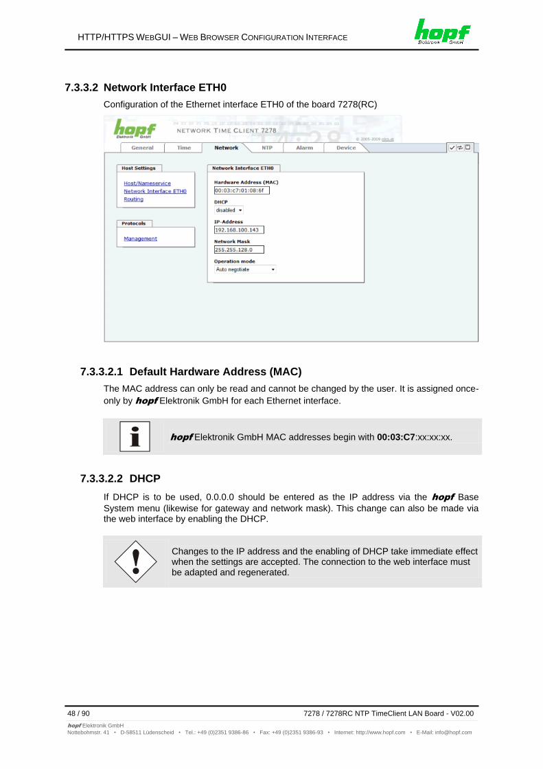
HTTP/HTTPS WEBGUI – WEB BROWSER CONFIGURATION INTERFACE
48 / 90 7278 / 7278RC NTP TimeClient LAN Board - V02.00
hopf Elektronik GmbH
Nottebohmstr. 41 • D-58511 Lüdenscheid • Tel.: +49 (0)2351 9386-86 • Fax: +49 (0)2351 9386-93 • Internet: http://www.hopf.com • E-Mail: [email protected]
7.3.3.2 Network Interface ETH0
Configuration of the Ethernet interface ETH0 of the board 7278(RC)
7.3.3.2.1 Default Hardware Address (MAC)
The MAC address can only be read and cannot be changed by the user. It is assigned once-
only by hopf Elektronik GmbH for each Ethernet interface.
hopf Elektronik GmbH MAC addresses begin with 00:03:C7:xx:xx:xx.
7.3.3.2.2 DHCP
If DHCP is to be used, 0.0.0.0 should be entered as the IP address via the hopf Base
System menu (likewise for gateway and network mask). This change can also be made via the web interface by enabling the DHCP.
Changes to the IP address and the enabling of DHCP take immediate effect when the settings are accepted. The connection to the web interface must be adapted and regenerated.
HTTP/HTTPS WEBGUI – WEB BROWSER CONFIGURATION INTERFACE
7278 / 7278RC NTP TimeClient LAN Board - V02.00 49 / 90
hopf Elektronik GmbH
Nottebohmstr. 41 • D-58511 Lüdenscheid • Tel.: +49 (0)2351 9386-86 • Fax: +49 (0)2351 9386-93 • Internet: http://www.hopf.com • E-Mail: [email protected]
7.3.3.2.3 IP Address
The IP address is generally configured via the hopf Base System menu. However it can
also be changed via the web interface.
In Base System 7001 / 68xx, the changed LAN configuration is only stored in the Board’s flash memory and is ALWAYS overwritten when a new value is entered. Data changed via the LAN is not updated in the Base System and thus is no longer displayed correctly after the change. For this reason it is recommended to configure the IP address via the Base System.
Contact your network administrator for details of the IP address if not known.
7.3.3.2.4 Network Mask
The network mask is generally configured via the hopf Base System menu. However it can
also be changed via the web interface.
In the Base System 7001 / 68xx, the changed LAN configuration is only stored in the Board’s flash memory and is ALWAYS overwritten when a new value is entered. Data changed via the LAN is not updated in the Base System and thus is no longer displayed correctly after the change. For this reason it is recommended to configure the network mask via the Base System.
Contact your network administrator for details of the network mask if not known.
7.3.3.2.5 Operation Mode
The network device usually adjusts the data stream and duplex mode to the device to which it is connected (e.g. HUB, SWITCH) automatically. If the network device requires a certain speed or duplex mode, this can be configured via the web interface. The value should only be changed in special cases. The automatic setting is normally used.
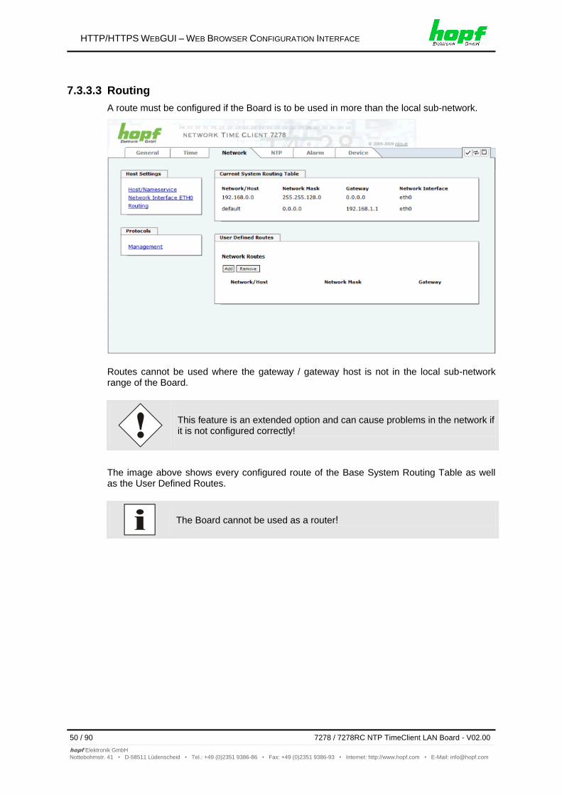
HTTP/HTTPS WEBGUI – WEB BROWSER CONFIGURATION INTERFACE
50 / 90 7278 / 7278RC NTP TimeClient LAN Board - V02.00
hopf Elektronik GmbH
Nottebohmstr. 41 • D-58511 Lüdenscheid • Tel.: +49 (0)2351 9386-86 • Fax: +49 (0)2351 9386-93 • Internet: http://www.hopf.com • E-Mail: [email protected]
7.3.3.3 Routing
A route must be configured if the Board is to be used in more than the local sub-network.
Routes cannot be used where the gateway / gateway host is not in the local sub-network range of the Board.
This feature is an extended option and can cause problems in the network if it is not configured correctly!
The image above shows every configured route of the Base System Routing Table as well as the User Defined Routes.
The Board cannot be used as a router!
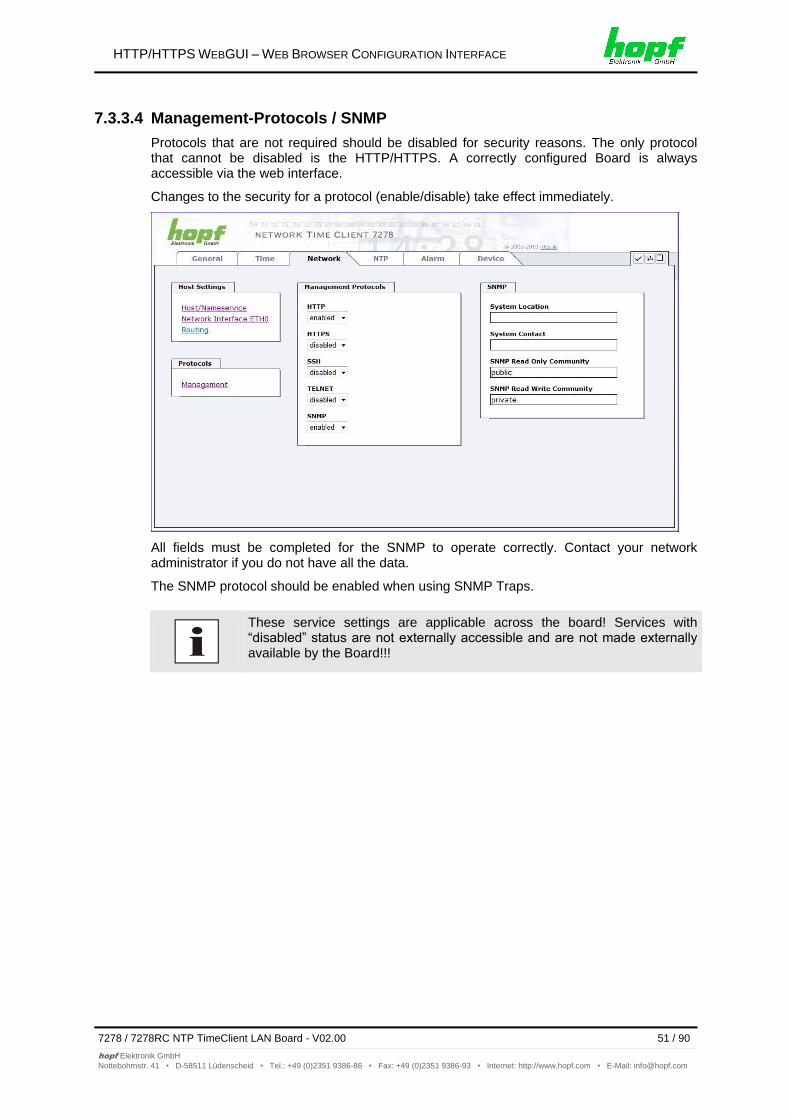
HTTP/HTTPS WEBGUI – WEB BROWSER CONFIGURATION INTERFACE
7278 / 7278RC NTP TimeClient LAN Board - V02.00 51 / 90
hopf Elektronik GmbH
Nottebohmstr. 41 • D-58511 Lüdenscheid • Tel.: +49 (0)2351 9386-86 • Fax: +49 (0)2351 9386-93 • Internet: http://www.hopf.com • E-Mail: [email protected]
7.3.3.4 Management-Protocols / SNMP
Protocols that are not required should be disabled for security reasons. The only protocol that cannot be disabled is the HTTP/HTTPS. A correctly configured Board is always accessible via the web interface.
Changes to the security for a protocol (enable/disable) take effect immediately.
All fields must be completed for the SNMP to operate correctly. Contact your network administrator if you do not have all the data.
The SNMP protocol should be enabled when using SNMP Traps.
These service settings are applicable across the board! Services with “disabled” status are not externally accessible and are not made externally available by the Board!!!
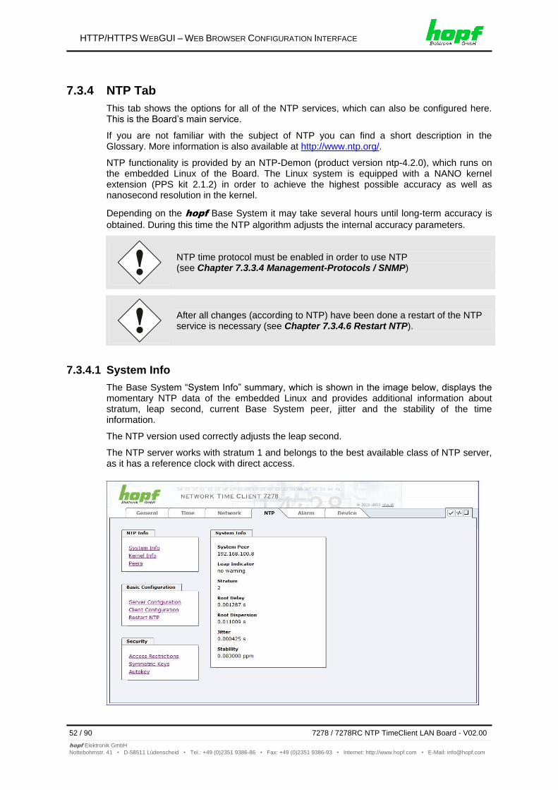
HTTP/HTTPS WEBGUI – WEB BROWSER CONFIGURATION INTERFACE
52 / 90 7278 / 7278RC NTP TimeClient LAN Board - V02.00
hopf Elektronik GmbH
Nottebohmstr. 41 • D-58511 Lüdenscheid • Tel.: +49 (0)2351 9386-86 • Fax: +49 (0)2351 9386-93 • Internet: http://www.hopf.com • E-Mail: [email protected]
7.3.4 NTP Tab
This tab shows the options for all of the NTP services, which can also be configured here. This is the Board’s main service.
If you are not familiar with the subject of NTP you can find a short description in the Glossary. More information is also available at http://www.ntp.org/.
NTP functionality is provided by an NTP-Demon (product version ntp-4.2.0), which runs on the embedded Linux of the Board. The Linux system is equipped with a NANO kernel extension (PPS kit 2.1.2) in order to achieve the highest possible accuracy as well as nanosecond resolution in the kernel.
Depending on the hopf Base System it may take several hours until long-term accuracy is
obtained. During this time the NTP algorithm adjusts the internal accuracy parameters.
NTP time protocol must be enabled in order to use NTP (see Chapter 7.3.3.4 Management-Protocols / SNMP)
After all changes (according to NTP) have been done a restart of the NTP service is necessary (see Chapter 7.3.4.6 Restart NTP).
7.3.4.1 System Info
The Base System “System Info” summary, which is shown in the image below, displays the momentary NTP data of the embedded Linux and provides additional information about stratum, leap second, current Base System peer, jitter and the stability of the time information.
The NTP version used correctly adjusts the leap second.
The NTP server works with stratum 1 and belongs to the best available class of NTP server, as it has a reference clock with direct access.
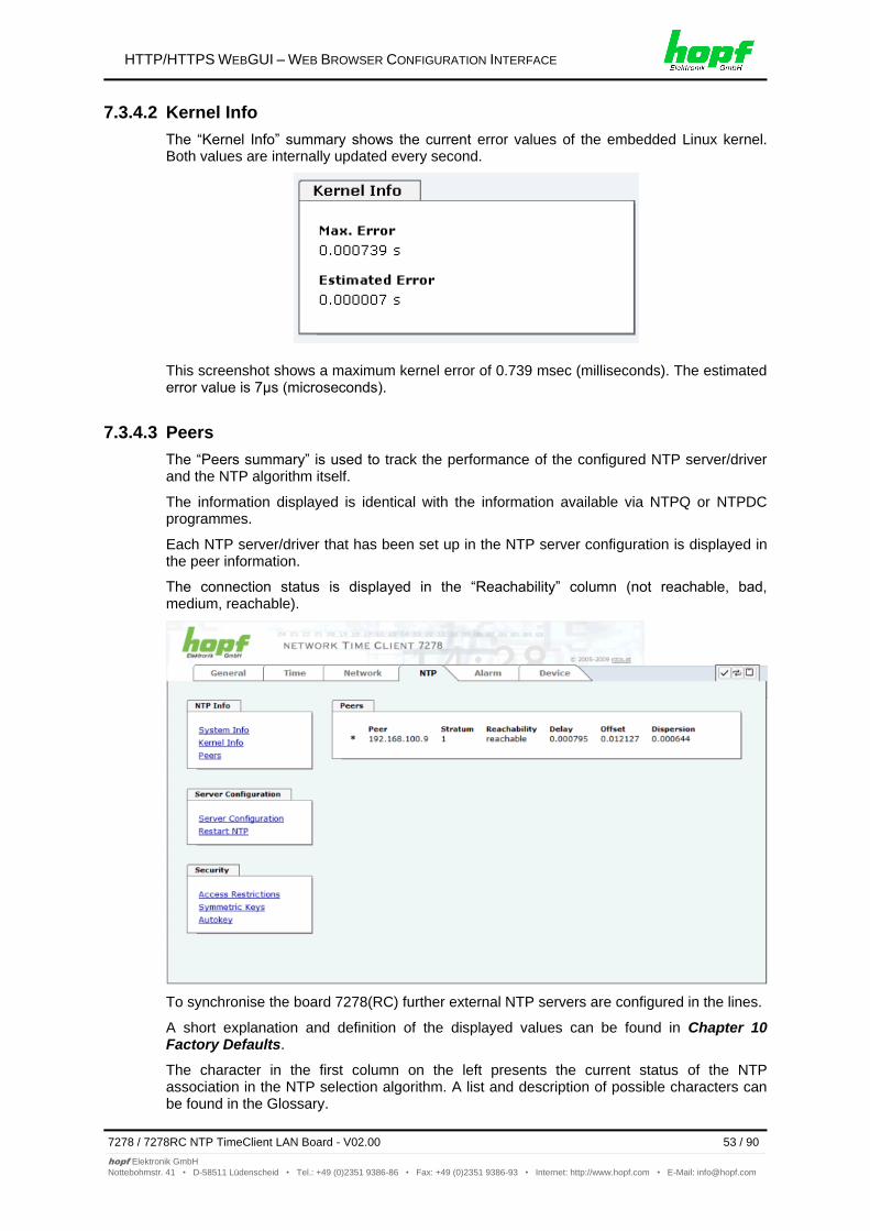
HTTP/HTTPS WEBGUI – WEB BROWSER CONFIGURATION INTERFACE
7278 / 7278RC NTP TimeClient LAN Board - V02.00 53 / 90
hopf Elektronik GmbH
Nottebohmstr. 41 • D-58511 Lüdenscheid • Tel.: +49 (0)2351 9386-86 • Fax: +49 (0)2351 9386-93 • Internet: http://www.hopf.com • E-Mail: [email protected]
7.3.4.2 Kernel Info
The “Kernel Info” summary shows the current error values of the embedded Linux kernel. Both values are internally updated every second.
This screenshot shows a maximum kernel error of 0.739 msec (milliseconds). The estimated error value is 7μs (microseconds).
7.3.4.3 Peers
The “Peers summary” is used to track the performance of the configured NTP server/driver and the NTP algorithm itself.
The information displayed is identical with the information available via NTPQ or NTPDC programmes.
Each NTP server/driver that has been set up in the NTP server configuration is displayed in the peer information.
The connection status is displayed in the “Reachability” column (not reachable, bad, medium, reachable).
To synchronise the board 7278(RC) further external NTP servers are configured in the lines.
A short explanation and definition of the displayed values can be found in Chapter 10 Factory Defaults.
The character in the first column on the left presents the current status of the NTP association in the NTP selection algorithm. A list and description of possible characters can be found in the Glossary.
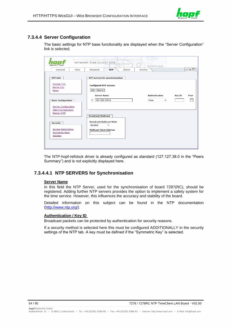
HTTP/HTTPS WEBGUI – WEB BROWSER CONFIGURATION INTERFACE
54 / 90 7278 / 7278RC NTP TimeClient LAN Board - V02.00
hopf Elektronik GmbH
Nottebohmstr. 41 • D-58511 Lüdenscheid • Tel.: +49 (0)2351 9386-86 • Fax: +49 (0)2351 9386-93 • Internet: http://www.hopf.com • E-Mail: [email protected]
7.3.4.4 Server Configuration
The basic settings for NTP base functionality are displayed when the “Server Configuration” link is selected.
The NTP-hopf-refclock driver is already configured as standard (127.127.38.0 in the “Peers Summary”) and is not explicitly displayed here.
7.3.4.4.1 NTP SERVERS for Synchronisation
Server Name
In this field the NTP Server, used for the synchronisation of board 7287(RC), should be registered. Adding further NTP servers provides the option to implement a safety system for the time service. However, this influences the accuracy and stability of the board.
Detailed information on this subject can be found in the NTP documentation (http://www.ntp.org/).
Authentication / Key ID
Broadcast packets can be protected by authentication for security reasons.
If a security method is selected here this must be configured ADDITIONALLY in the security settings of the NTP tab. A key must be defined if the “Symmetric Key” is selected.
HTTP/HTTPS WEBGUI – WEB BROWSER CONFIGURATION INTERFACE
7278 / 7278RC NTP TimeClient LAN Board - V02.00 55 / 90
hopf Elektronik GmbH
Nottebohmstr. 41 • D-58511 Lüdenscheid • Tel.: +49 (0)2351 9386-86 • Fax: +49 (0)2351 9386-93 • Internet: http://www.hopf.com • E-Mail: [email protected]
7.3.4.4.2 Broadcast / Multicast
This section is used to synchronize the Board with a broadcast or multicast server.
The broadcast mode in NTPv3 and NTPv4 is limited to clients on the same sub-network and Ethernet which support broadcast technology.
This technology does not generally extend beyond the first hop (such as router or gateway).
The server continuously generates broadcast messages at defined intervals, corresponding to 16 seconds (minpoll 4) on the LAN Board. Care should be taken to ensure that the correct broadcast address is used for the sub-network, usually xxx.xxx.xxx.255 (e.g. 192.168.1.255). If the broadcast address is not known, this can be requested from the network administrator.
This section can also be used to configure the LAN Board as a multicast server. The configuration of a multicast server is similar to that of a broadcast server. However, a multicast group address (class D) is used instead of the broadcast address.
An explanation of multicast technology goes beyond the scope of this document.
In principle, a host or router sends a message to an Ipv4 multicast group address and expects all hosts and routers to receive this message. In doing so, there is no limit to the number of senders and receivers and a sender may also be a receiver and vice-versa. The IANA has assigned the multicast group address IPv4 224.0.1.1 to the NTP, however this should only be used if the multicast range can be safely limited in order to protect neighbouring networks. As a basic principle, administratively manageable IPv4 group addresses should be used as described in RFC-2365 or GLOP group addresses as described in RFC-2770.
7.3.4.5 Client Configuration
The synchronisation acquisition of board 7278(RC) can be adjusted following the link "Client Configuration". This function allows board 7278(RC) to synchronise the connected base System with inaccurate NTP server. Reasons for inaccurate NTP server could be e.g. poor network performance, poor own accuracy or bad availability.
This function should usually be disabled and only be used if required.
When using this function the specified accuracy of board 7278(RC) and
thus the accuracy of the synchronized hopf base System can be worsen.
When using this function the specified data of NTP accuracy stated in the technical data of board 7278(RC) are not valid anymore.
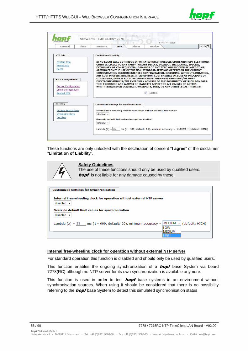
HTTP/HTTPS WEBGUI – WEB BROWSER CONFIGURATION INTERFACE
56 / 90 7278 / 7278RC NTP TimeClient LAN Board - V02.00
hopf Elektronik GmbH
Nottebohmstr. 41 • D-58511 Lüdenscheid • Tel.: +49 (0)2351 9386-86 • Fax: +49 (0)2351 9386-93 • Internet: http://www.hopf.com • E-Mail: [email protected]
These functions are only unlocked with the declaration of consent "I agree" of the disclaimer "Limitation of Liability".
Safety Guidelines The use of these functions should only be used by qualified users.
hopf is not liable for any damage caused by these.
Internal free-wheeling clock for operation without external NTP server
For standard operation this function is disabled and should only be used by qualified users.
This function enables the ongoing synchronization of a hopf base System via board
7278(RC) although no NTP server for its own synchronization is available anymore.
This function is used in order to test hopf base systems in an environment without
synchronisation sources. When using it should be considered that there is no possibility
referring to the hopf base System to detect this simulated synchronisation status
HTTP/HTTPS WEBGUI – WEB BROWSER CONFIGURATION INTERFACE
7278 / 7278RC NTP TimeClient LAN Board - V02.00 57 / 90
hopf Elektronik GmbH
Nottebohmstr. 41 • D-58511 Lüdenscheid • Tel.: +49 (0)2351 9386-86 • Fax: +49 (0)2351 9386-93 • Internet: http://www.hopf.com • E-Mail: [email protected]
Modification of values do not cause an immediate effect when clicking on the apply symbol. In addition the NTP service must be restarted (see chapter 7.3.4.6 Restart NTP).
Override default limit values for synchronization
For standard operation this function is disabled and should only be used by qualified users.
Lambda (λ)
For observance of specified accuracy of board 7278(RC), board 7278(RC) uses only accurate NTP server for synchronisation which have an accuracy value for lambda better 20ms.
In case it is required that board 7278(RC) should be synchronized on an more inaccurate NTP server the threshold accuracy value for lambda can be adjusted by this function.
Therefore, the function "Override default limit values for synchronisation" needs to be activated and to configure the required accuracy value for lambda (1-999ms).
The use of this function for synchronisation through an inaccurate NTP server, board 7278(RC) might likely not keep its specified accuracy anymore.
Minimum Accuracy
Only with the accuracy status accuracy = high board 7278(RC) synchronizes the connected base System.
This function can be used for NTP server not being able to synchronize board 7278(RC) with the required accuracy. The accuracy value (accuracy = high / medium / low) for synchronisation of the base System is adjusted by it. However, the base System can only then be synchronized with the according accuracy.
Modification of values do not cause an immediate effect when clicking on the apply symbol. In addition the NTP service must be restarted (see Chapter 7.3.6.4 Reboot Device).
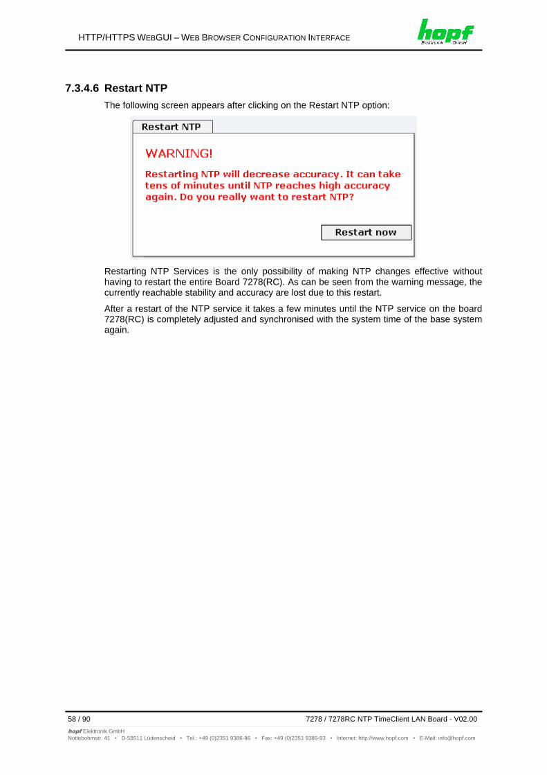
HTTP/HTTPS WEBGUI – WEB BROWSER CONFIGURATION INTERFACE
58 / 90 7278 / 7278RC NTP TimeClient LAN Board - V02.00
hopf Elektronik GmbH
Nottebohmstr. 41 • D-58511 Lüdenscheid • Tel.: +49 (0)2351 9386-86 • Fax: +49 (0)2351 9386-93 • Internet: http://www.hopf.com • E-Mail: [email protected]
7.3.4.6 Restart NTP
The following screen appears after clicking on the Restart NTP option:
Restarting NTP Services is the only possibility of making NTP changes effective without having to restart the entire Board 7278(RC). As can be seen from the warning message, the currently reachable stability and accuracy are lost due to this restart.
After a restart of the NTP service it takes a few minutes until the NTP service on the board 7278(RC) is completely adjusted and synchronised with the system time of the base system again.
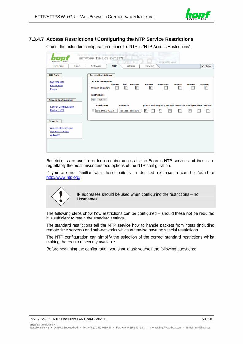
HTTP/HTTPS WEBGUI – WEB BROWSER CONFIGURATION INTERFACE
7278 / 7278RC NTP TimeClient LAN Board - V02.00 59 / 90
hopf Elektronik GmbH
Nottebohmstr. 41 • D-58511 Lüdenscheid • Tel.: +49 (0)2351 9386-86 • Fax: +49 (0)2351 9386-93 • Internet: http://www.hopf.com • E-Mail: [email protected]
7.3.4.7 Access Restrictions / Configuring the NTP Service Restrictions
One of the extended configuration options for NTP is “NTP Access Restrictions”.
Restrictions are used in order to control access to the Board’s NTP service and these are regrettably the most misunderstood options of the NTP configuration.
If you are not familiar with these options, a detailed explanation can be found at http://www.ntp.org/.
IP addresses should be used when configuring the restrictions – no Hostnames!
The following steps show how restrictions can be configured – should these not be required it is sufficient to retain the standard settings.
The standard restrictions tell the NTP service how to handle packets from hosts (including remote time servers) and sub-networks which otherwise have no special restrictions.
The NTP configuration can simplify the selection of the correct standard restrictions whilst making the required security available.
Before beginning the configuration you should ask yourself the following questions:
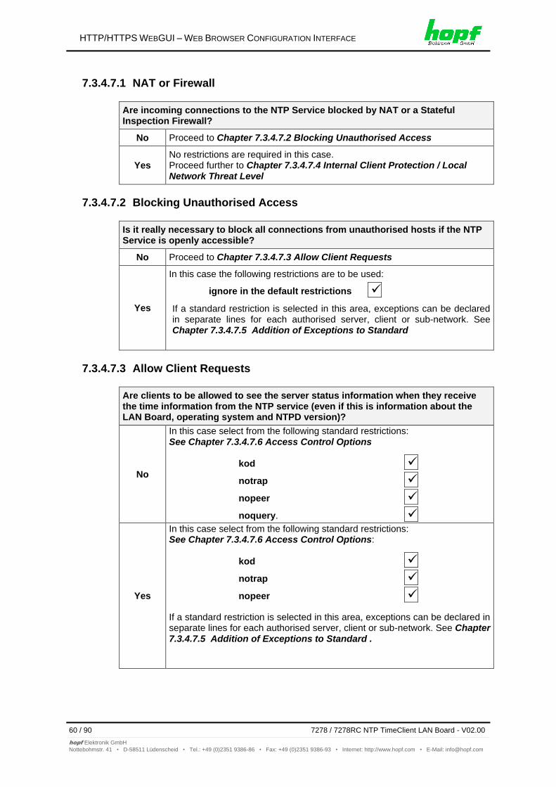
HTTP/HTTPS WEBGUI – WEB BROWSER CONFIGURATION INTERFACE
60 / 90 7278 / 7278RC NTP TimeClient LAN Board - V02.00
hopf Elektronik GmbH
Nottebohmstr. 41 • D-58511 Lüdenscheid • Tel.: +49 (0)2351 9386-86 • Fax: +49 (0)2351 9386-93 • Internet: http://www.hopf.com • E-Mail: [email protected]
7.3.4.7.1 NAT or Firewall
Are incoming connections to the NTP Service blocked by NAT or a Stateful Inspection Firewall?
No Proceed to Chapter 7.3.4.7.2 Blocking Unauthorised Access
Yes No restrictions are required in this case. Proceed further to Chapter 7.3.4.7.4 Internal Client Protection / Local Network Threat Level
7.3.4.7.2 Blocking Unauthorised Access
Is it really necessary to block all connections from unauthorised hosts if the NTP Service is openly accessible?
No Proceed to Chapter 7.3.4.7.3 Allow Client Requests
Yes
In this case the following restrictions are to be used:
ignore in the default restrictions
If a standard restriction is selected in this area, exceptions can be declared in separate lines for each authorised server, client or sub-network. See Chapter 7.3.4.7.5 Addition of Exceptions to Standard
7.3.4.7.3 Allow Client Requests
Are clients to be allowed to see the server status information when they receive the time information from the NTP service (even if this is information about the LAN Board, operating system and NTPD version)?
No
In this case select from the following standard restrictions: See Chapter 7.3.4.7.6 Access Control Options
kod
notrap
nopeer
noquery.
Yes
In this case select from the following standard restrictions: See Chapter 7.3.4.7.6 Access Control Options:
kod
notrap
nopeer
If a standard restriction is selected in this area, exceptions can be declared in separate lines for each authorised server, client or sub-network. See Chapter 7.3.4.7.5 Addition of Exceptions to Standard .
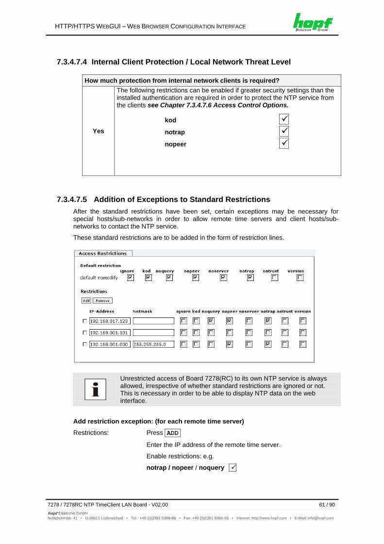
HTTP/HTTPS WEBGUI – WEB BROWSER CONFIGURATION INTERFACE
7278 / 7278RC NTP TimeClient LAN Board - V02.00 61 / 90
hopf Elektronik GmbH
Nottebohmstr. 41 • D-58511 Lüdenscheid • Tel.: +49 (0)2351 9386-86 • Fax: +49 (0)2351 9386-93 • Internet: http://www.hopf.com • E-Mail: [email protected]
7.3.4.7.4 Internal Client Protection / Local Network Threat Level
How much protection from internal network clients is required?
Yes
The following restrictions can be enabled if greater security settings than the installed authentication are required in order to protect the NTP service from the clients see Chapter 7.3.4.7.6 Access Control Options.
kod
notrap
nopeer
7.3.4.7.5 Addition of Exceptions to Standard Restrictions
After the standard restrictions have been set, certain exceptions may be necessary for special hosts/sub-networks in order to allow remote time servers and client hosts/sub-networks to contact the NTP service.
These standard restrictions are to be added in the form of restriction lines.
Unrestricted access of Board 7278(RC) to its own NTP service is always allowed, irrespective of whether standard restrictions are ignored or not. This is necessary in order to be able to display NTP data on the web interface.
Add restriction exception: (for each remote time server)
Restrictions: Press ADD
Enter the IP address of the remote time server.
Enable restrictions: e.g.
notrap / nopeer / noquery
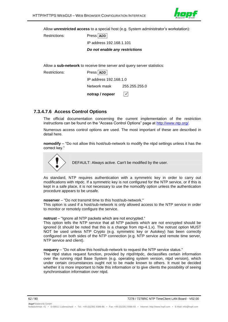
HTTP/HTTPS WEBGUI – WEB BROWSER CONFIGURATION INTERFACE
62 / 90 7278 / 7278RC NTP TimeClient LAN Board - V02.00
hopf Elektronik GmbH
Nottebohmstr. 41 • D-58511 Lüdenscheid • Tel.: +49 (0)2351 9386-86 • Fax: +49 (0)2351 9386-93 • Internet: http://www.hopf.com • E-Mail: [email protected]
Allow unrestricted access to a special host (e.g. System administrator’s workstation):
Restrictions: Press ADD
IP address 192.168.1.101
Do not enable any restrictions
Allow a sub-network to receive time server and query server statistics:
Restrictions: Press ADD
IP address 192.168.1.0
Network mask 255.255.255.0
notrap / nopeer
7.3.4.7.6 Access Control Options
The official documentation concerning the current implementation of the restriction instructions can be found on the “Access Control Options” page at http://www.ntp.org/.
Numerous access control options are used. The most important of these are described in detail here.
nomodify – "Do not allow this host/sub-network to modify the ntpd settings unless it has the correct key.“
DEFAULT: Always active. Can't be modified by the user.
As standard, NTP requires authentication with a symmetric key in order to carry out modifications with ntpdc. If a symmetric key is not configured for the NTP service, or if this is kept in a safe place, it is not necessary to use the nomodify option unless the authentication procedure appears to be unsafe.
noserver – "Do not transmit time to this host/sub-network." This option is used if a host/sub-network is only allowed access to the NTP service in order to monitor or remotely configure the service.
notrust – "Ignore all NTP packets which are not encrypted.“ This option tells the NTP service that all NTP packets which are not encrypted should be ignored (it should be noted that this is a change from ntp-4.1.x). The notrust option MUST NOT be used unless NTP Crypto (e.g. symmetric key or Autokey) has been correctly configured on both sides of the NTP connection (e.g. NTP service and remote time server, NTP service and client).
noquery – "Do not allow this host/sub-network to request the NTP service status." The ntpd status request function, provided by ntpd/ntpdc, declassifies certain information over the running ntpd Base System (e.g. operating system version, ntpd version), which under certain circumstances ought not to be made known to others. It must be decided whether it is more important to hide this information or to give clients the possibility of seeing synchronisation information over ntpd.
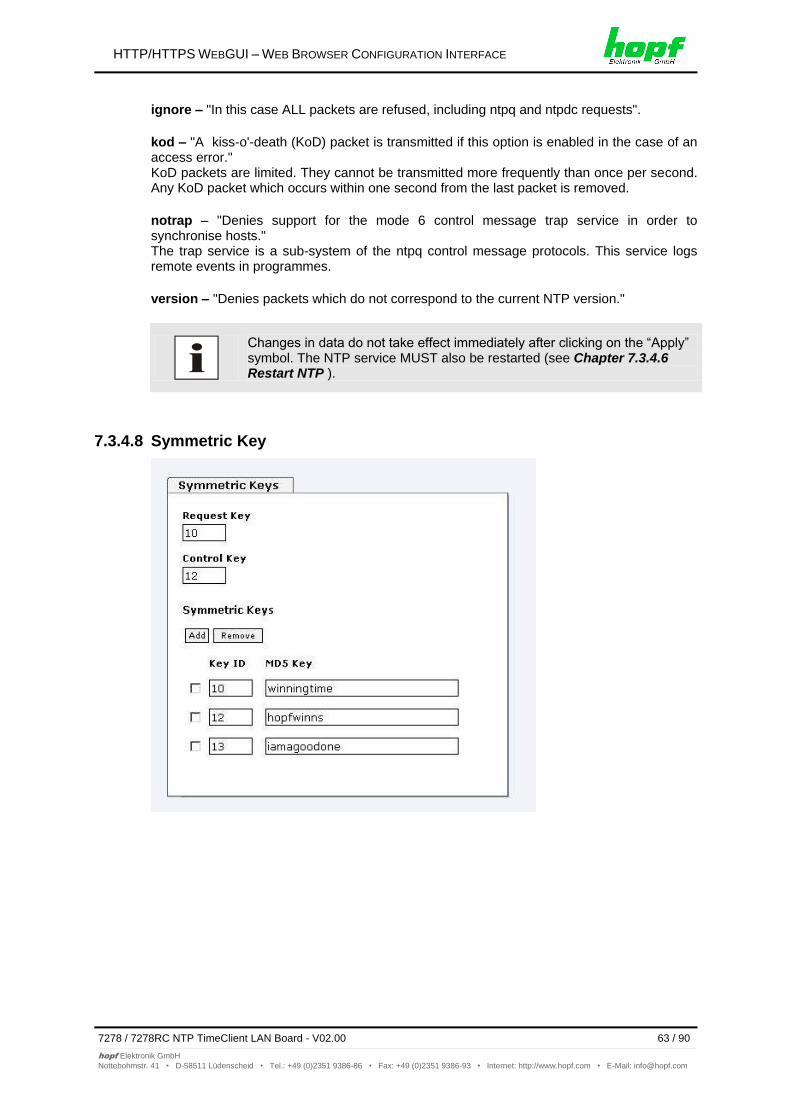
HTTP/HTTPS WEBGUI – WEB BROWSER CONFIGURATION INTERFACE
7278 / 7278RC NTP TimeClient LAN Board - V02.00 63 / 90
hopf Elektronik GmbH
Nottebohmstr. 41 • D-58511 Lüdenscheid • Tel.: +49 (0)2351 9386-86 • Fax: +49 (0)2351 9386-93 • Internet: http://www.hopf.com • E-Mail: [email protected]
ignore – "In this case ALL packets are refused, including ntpq and ntpdc requests".
kod – "A kiss-o'-death (KoD) packet is transmitted if this option is enabled in the case of an access error." KoD packets are limited. They cannot be transmitted more frequently than once per second. Any KoD packet which occurs within one second from the last packet is removed.
notrap – "Denies support for the mode 6 control message trap service in order to synchronise hosts." The trap service is a sub-system of the ntpq control message protocols. This service logs remote events in programmes.
version – "Denies packets which do not correspond to the current NTP version."
Changes in data do not take effect immediately after clicking on the “Apply” symbol. The NTP service MUST also be restarted (see Chapter 7.3.4.6 Restart NTP ).
7.3.4.8 Symmetric Key
HTTP/HTTPS WEBGUI – WEB BROWSER CONFIGURATION INTERFACE
64 / 90 7278 / 7278RC NTP TimeClient LAN Board - V02.00
hopf Elektronik GmbH
Nottebohmstr. 41 • D-58511 Lüdenscheid • Tel.: +49 (0)2351 9386-86 • Fax: +49 (0)2351 9386-93 • Internet: http://www.hopf.com • E-Mail: [email protected]
7.3.4.8.1 Why Authentication?
Most NTP users do not require authentication as the protocol contains several filters (for bad time).
Despite this, however, the use of authentication is common.
There are certain reasons for this:
Time should only be used from safe sources
An attacker broadcasts false time signals
An attacker poses as another time server
7.3.4.8.2 How is Authentication used in the NTP Service?
Client and server can execute an authentication whereby a code word is used on the client side and a restriction on the server side.
NTP uses keys to implement the authentication. These keys are used when data is exchanged between two machines.
In principle both sides must know this key. The key can generally be found in the “*.*/etc/ntp.keys“ directory. It is unencrypted and hidden from public view. This means that the key has to be distributed on a safe route to all communication partners. The key can be downloaded for distribution under “Downloads” on the DEVICE tab. It is necessary to be logged in as “Master” in order to access this.
The keyword key of a client’s ntp.conf determines the key that is used to communicate with the designated server (e.g. the NTS board). The key must be reliable if time is to be synchronised. Authentication causes a delay. This delay is automatically taken into account and adjusted in the current versions.
7.3.4.8.3 How is a key created?
A key is a sequence of up to 31 ASCII characters. Some characters with special significance cannot be used (alphanumeric characters and the following symbols can be used:[ ] ( ) * - _ ! $ % & / = ?).
A new line can be inserted by pressing the ADD key. The key which is stored in the key file
is entered on this line. The key ID is used to identify the key and is in the range from 1 – 65534. This means that 65534 different keys can be defined.
Duplicate key ID’s are not allowed. Having now explained the principles of keys, it should be possible to use a key in practically the same way as a password.
The value of the request key field is used as the password for the ntpdc tool while the value of the control key field is used as the password for the ntpq tool.
More information is available at http://www.ntp.org/.
7.3.4.8.4 How does authentication work?
Basic authentication is a digital signature and not data encryption (if there is any difference between the two). The data packet and the key are used to create a non-reversible number which is attached to the packet.
The receiver (which has the same key) carries out the same calculation and compares the results. Authentication has been successful if the results concur.
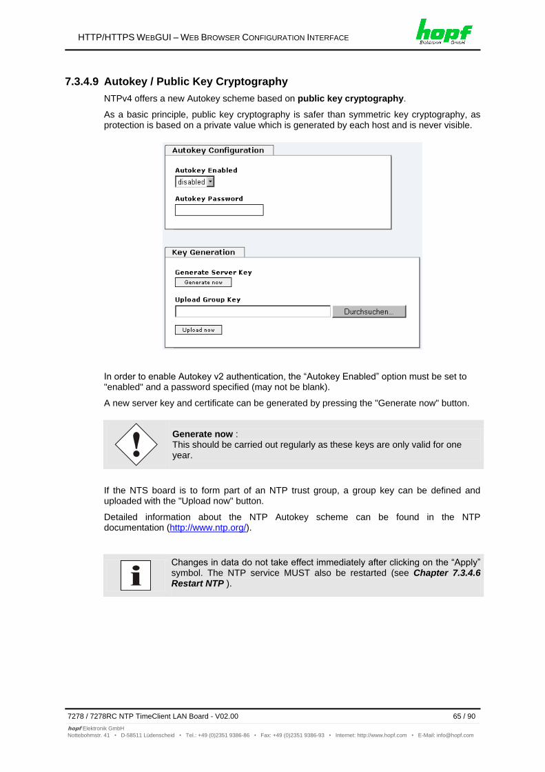
HTTP/HTTPS WEBGUI – WEB BROWSER CONFIGURATION INTERFACE
7278 / 7278RC NTP TimeClient LAN Board - V02.00 65 / 90
hopf Elektronik GmbH
Nottebohmstr. 41 • D-58511 Lüdenscheid • Tel.: +49 (0)2351 9386-86 • Fax: +49 (0)2351 9386-93 • Internet: http://www.hopf.com • E-Mail: [email protected]
7.3.4.9 Autokey / Public Key Cryptography
NTPv4 offers a new Autokey scheme based on public key cryptography.
As a basic principle, public key cryptography is safer than symmetric key cryptography, as protection is based on a private value which is generated by each host and is never visible.
In order to enable Autokey v2 authentication, the “Autokey Enabled” option must be set to "enabled" and a password specified (may not be blank).
A new server key and certificate can be generated by pressing the "Generate now" button.
Generate now : This should be carried out regularly as these keys are only valid for one year.
If the NTS board is to form part of an NTP trust group, a group key can be defined and uploaded with the "Upload now" button.
Detailed information about the NTP Autokey scheme can be found in the NTP documentation (http://www.ntp.org/).
Changes in data do not take effect immediately after clicking on the “Apply” symbol. The NTP service MUST also be restarted (see Chapter 7.3.4.6 Restart NTP ).
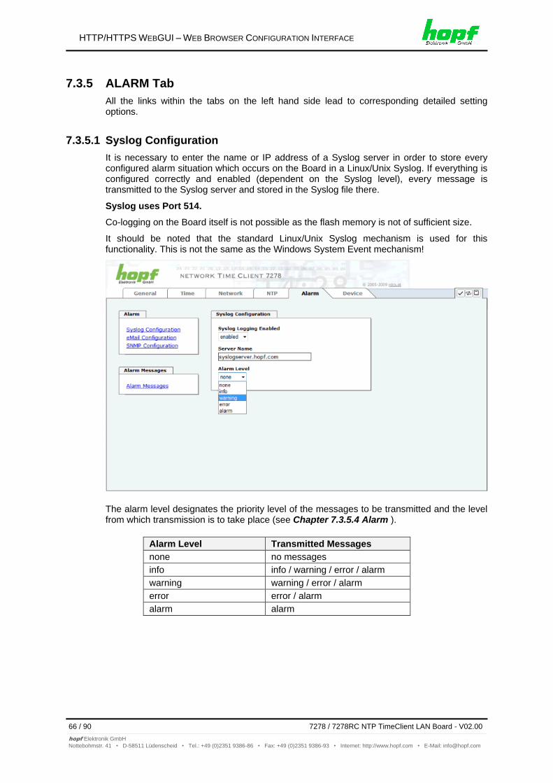
HTTP/HTTPS WEBGUI – WEB BROWSER CONFIGURATION INTERFACE
66 / 90 7278 / 7278RC NTP TimeClient LAN Board - V02.00
hopf Elektronik GmbH
Nottebohmstr. 41 • D-58511 Lüdenscheid • Tel.: +49 (0)2351 9386-86 • Fax: +49 (0)2351 9386-93 • Internet: http://www.hopf.com • E-Mail: [email protected]
7.3.5 ALARM Tab
All the links within the tabs on the left hand side lead to corresponding detailed setting options.
7.3.5.1 Syslog Configuration
It is necessary to enter the name or IP address of a Syslog server in order to store every configured alarm situation which occurs on the Board in a Linux/Unix Syslog. If everything is configured correctly and enabled (dependent on the Syslog level), every message is transmitted to the Syslog server and stored in the Syslog file there.
Syslog uses Port 514.
Co-logging on the Board itself is not possible as the flash memory is not of sufficient size.
It should be noted that the standard Linux/Unix Syslog mechanism is used for this functionality. This is not the same as the Windows System Event mechanism!
The alarm level designates the priority level of the messages to be transmitted and the level from which transmission is to take place (see Chapter 7.3.5.4 Alarm ).
Alarm Level Transmitted Messages
none no messages
info info / warning / error / alarm
warning warning / error / alarm
error error / alarm
alarm alarm
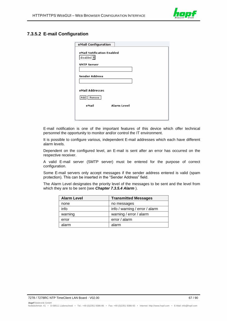
HTTP/HTTPS WEBGUI – WEB BROWSER CONFIGURATION INTERFACE
7278 / 7278RC NTP TimeClient LAN Board - V02.00 67 / 90
hopf Elektronik GmbH
Nottebohmstr. 41 • D-58511 Lüdenscheid • Tel.: +49 (0)2351 9386-86 • Fax: +49 (0)2351 9386-93 • Internet: http://www.hopf.com • E-Mail: [email protected]
7.3.5.2 E-mail Configuration
E-mail notification is one of the important features of this device which offer technical personnel the opportunity to monitor and/or control the IT environment.
It is possible to configure various, independent E-mail addresses which each have different alarm levels.
Dependent on the configured level, an E-mail is sent after an error has occurred on the respective receiver.
A valid E-mail server (SMTP server) must be entered for the purpose of correct configuration.
Some E-mail servers only accept messages if the sender address entered is valid (spam protection). This can be inserted in the “Sender Address” field.
The Alarm Level designates the priority level of the messages to be sent and the level from which they are to be sent (see Chapter 7.3.5.4 Alarm ).
Alarm Level Transmitted Messages
none no messages
info info / warning / error / alarm
warning warning / error / alarm
error error / alarm
alarm alarm
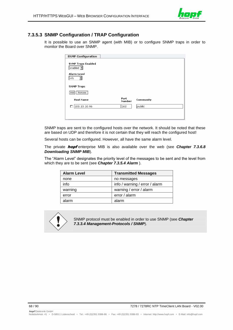
HTTP/HTTPS WEBGUI – WEB BROWSER CONFIGURATION INTERFACE
68 / 90 7278 / 7278RC NTP TimeClient LAN Board - V02.00
hopf Elektronik GmbH
Nottebohmstr. 41 • D-58511 Lüdenscheid • Tel.: +49 (0)2351 9386-86 • Fax: +49 (0)2351 9386-93 • Internet: http://www.hopf.com • E-Mail: [email protected]
7.3.5.3 SNMP Configuration / TRAP Configuration
It is possible to use an SNMP agent (with MIB) or to configure SNMP traps in order to monitor the Board over SNMP.
SNMP traps are sent to the configured hosts over the network. It should be noted that these are based on UDP and therefore it is not certain that they will reach the configured host!
Several hosts can be configured. However, all have the same alarm level.
The private hopf enterprise MIB is also available over the web (see Chapter 7.3.6.8
Downloading SNMP MIB).
The “Alarm Level” designates the priority level of the messages to be sent and the level from which they are to be sent (see Chapter 7.3.5.4 Alarm ).
Alarm Level Transmitted Messages
none no messages
info info / warning / error / alarm
warning warning / error / alarm
error error / alarm
alarm alarm
SNMP protocol must be enabled in order to use SNMP (see Chapter 7.3.3.4 Management-Protocols / SNMP).
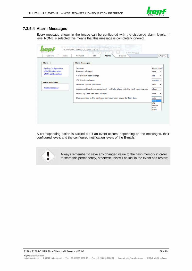
HTTP/HTTPS WEBGUI – WEB BROWSER CONFIGURATION INTERFACE
7278 / 7278RC NTP TimeClient LAN Board - V02.00 69 / 90
hopf Elektronik GmbH
Nottebohmstr. 41 • D-58511 Lüdenscheid • Tel.: +49 (0)2351 9386-86 • Fax: +49 (0)2351 9386-93 • Internet: http://www.hopf.com • E-Mail: [email protected]
7.3.5.4 Alarm Messages
Every message shown in the image can be configured with the displayed alarm levels. If level NONE is selected this means that this message is completely ignored.
A corresponding action is carried out if an event occurs, depending on the messages, their configured levels and the configured notification levels of the E-mails.
Always remember to save any changed value to the flash memory in order to store this permanently, otherwise this will be lost in the event of a restart!
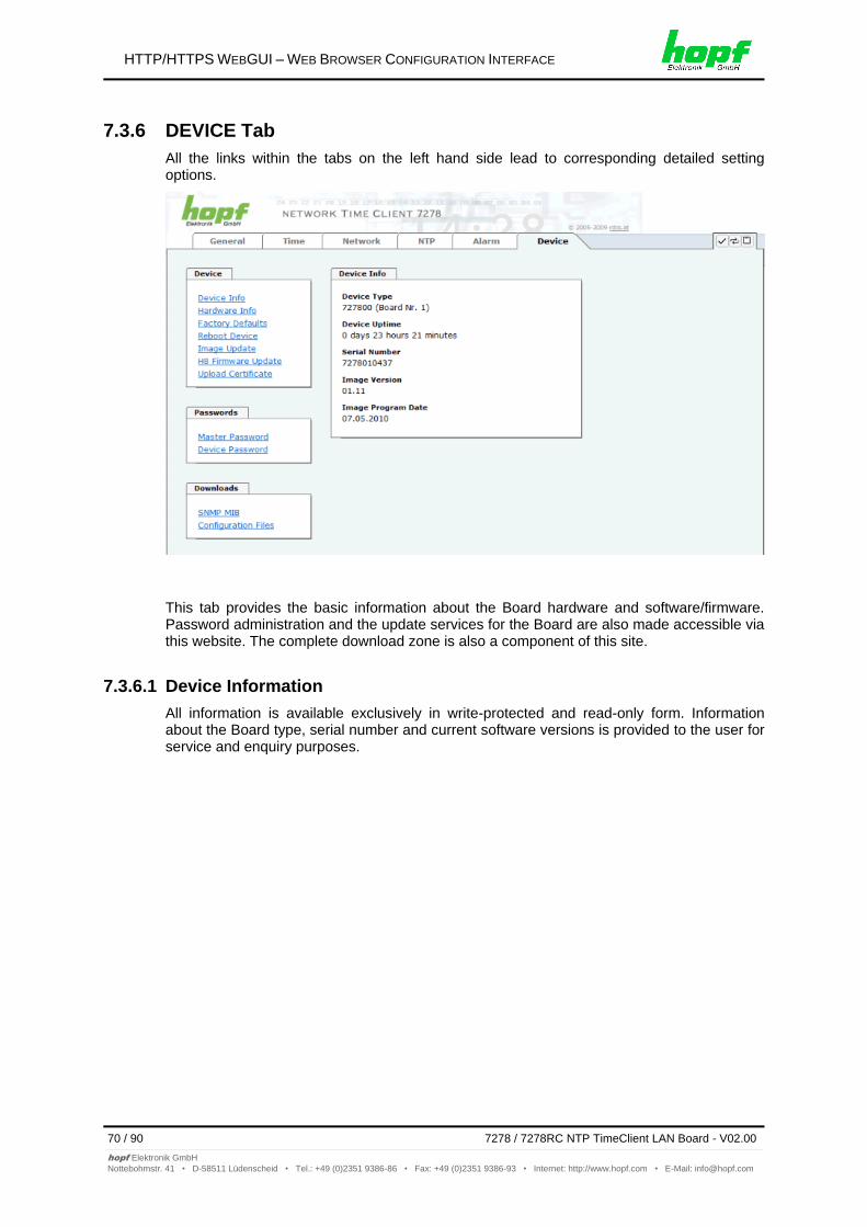
HTTP/HTTPS WEBGUI – WEB BROWSER CONFIGURATION INTERFACE
70 / 90 7278 / 7278RC NTP TimeClient LAN Board - V02.00
hopf Elektronik GmbH
Nottebohmstr. 41 • D-58511 Lüdenscheid • Tel.: +49 (0)2351 9386-86 • Fax: +49 (0)2351 9386-93 • Internet: http://www.hopf.com • E-Mail: [email protected]
7.3.6 DEVICE Tab
All the links within the tabs on the left hand side lead to corresponding detailed setting options.
This tab provides the basic information about the Board hardware and software/firmware. Password administration and the update services for the Board are also made accessible via this website. The complete download zone is also a component of this site.
7.3.6.1 Device Information
All information is available exclusively in write-protected and read-only form. Information about the Board type, serial number and current software versions is provided to the user for service and enquiry purposes.
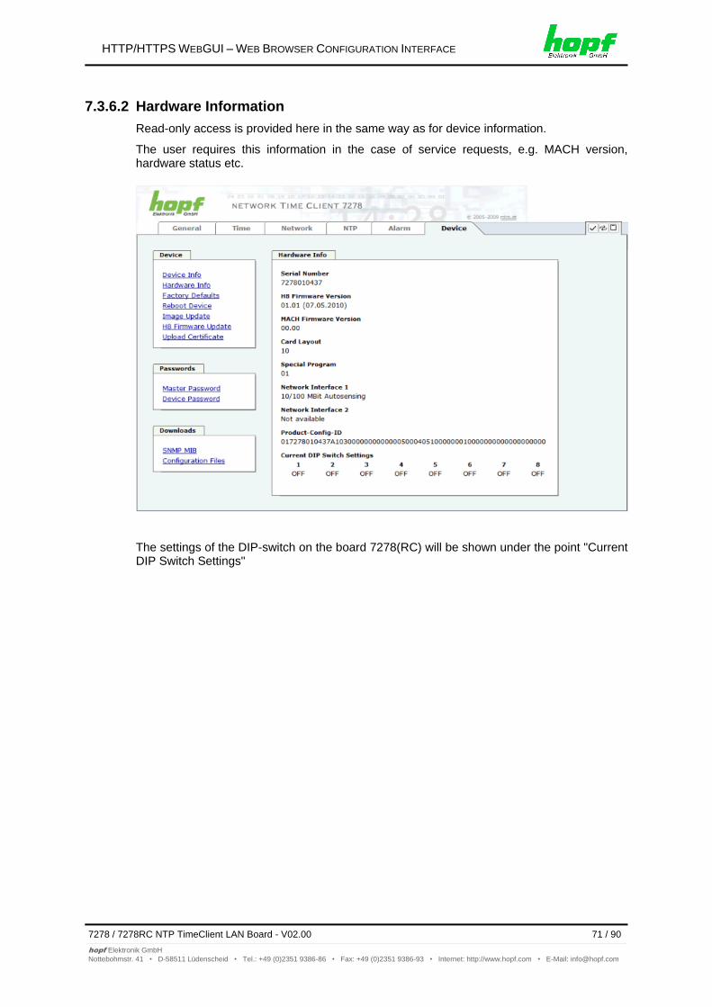
HTTP/HTTPS WEBGUI – WEB BROWSER CONFIGURATION INTERFACE
7278 / 7278RC NTP TimeClient LAN Board - V02.00 71 / 90
hopf Elektronik GmbH
Nottebohmstr. 41 • D-58511 Lüdenscheid • Tel.: +49 (0)2351 9386-86 • Fax: +49 (0)2351 9386-93 • Internet: http://www.hopf.com • E-Mail: [email protected]
7.3.6.2 Hardware Information
Read-only access is provided here in the same way as for device information.
The user requires this information in the case of service requests, e.g. MACH version, hardware status etc.
The settings of the DIP-switch on the board 7278(RC) will be shown under the point "Current DIP Switch Settings"
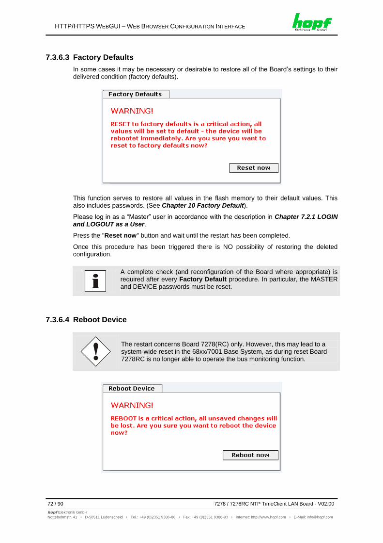
HTTP/HTTPS WEBGUI – WEB BROWSER CONFIGURATION INTERFACE
72 / 90 7278 / 7278RC NTP TimeClient LAN Board - V02.00
hopf Elektronik GmbH
Nottebohmstr. 41 • D-58511 Lüdenscheid • Tel.: +49 (0)2351 9386-86 • Fax: +49 (0)2351 9386-93 • Internet: http://www.hopf.com • E-Mail: [email protected]
7.3.6.3 Factory Defaults
In some cases it may be necessary or desirable to restore all of the Board’s settings to their delivered condition (factory defaults).
This function serves to restore all values in the flash memory to their default values. This also includes passwords. (See Chapter 10 Factory Default).
Please log in as a “Master” user in accordance with the description in Chapter 7.2.1 LOGIN and LOGOUT as a User.
Press the "Reset now" button and wait until the restart has been completed.
Once this procedure has been triggered there is NO possibility of restoring the deleted configuration.
A complete check (and reconfiguration of the Board where appropriate) is required after every Factory Default procedure. In particular, the MASTER and DEVICE passwords must be reset.
7.3.6.4 Reboot Device
The restart concerns Board 7278(RC) only. However, this may lead to a system-wide reset in the 68xx/7001 Base System, as during reset Board 7278RC is no longer able to operate the bus monitoring function.
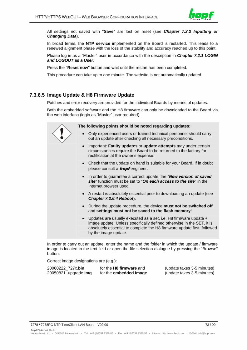
HTTP/HTTPS WEBGUI – WEB BROWSER CONFIGURATION INTERFACE
7278 / 7278RC NTP TimeClient LAN Board - V02.00 73 / 90
hopf Elektronik GmbH
Nottebohmstr. 41 • D-58511 Lüdenscheid • Tel.: +49 (0)2351 9386-86 • Fax: +49 (0)2351 9386-93 • Internet: http://www.hopf.com • E-Mail: [email protected]
All settings not saved with "Save" are lost on reset (see Chapter 7.2.3 Inputting or Changing Data).
In broad terms, the NTP service implemented on the Board is restarted. This leads to a renewed alignment phase with the loss of the stability and accuracy reached up to this point.
Please log in as a “Master” user in accordance with the description in Chapter 7.2.1 LOGIN and LOGOUT as a User.
Press the "Reset now" button and wait until the restart has been completed.
This procedure can take up to one minute. The website is not automatically updated.
7.3.6.5 Image Update & H8 Firmware Update
Patches and error recovery are provided for the individual Boards by means of updates.
Both the embedded software and the H8 firmware can only be downloaded to the Board via the web interface (login as “Master” user required).
The following points should be noted regarding updates:
Only experienced users or trained technical personnel should carry out an update after checking all necessary preconditions.
Important: Faulty updates or update attempts may under certain circumstances require the Board to be returned to the factory for rectification at the owner’s expense.
Check that the update on hand is suitable for your Board. If in doubt
please consult a hopf engineer.
In order to guarantee a correct update, the "New version of saved site" function must be set to "On each access to the site" in the Internet browser used.
A restart is absolutely essential prior to downloading an update (see Chapter 7.3.6.4 Reboot).
During the update procedure, the device must not be switched off and settings must not be saved to the flash memory!
Updates are usually executed as a set, i.e. H8 firmware update + image update. Unless specifically defined otherwise in the SET, it is absolutely essential to complete the H8 firmware update first, followed by the image update.
In order to carry out an update, enter the name and the folder in which the update / firmware image is located in the text field or open the file selection dialogue by pressing the "Browse" button.
Correct image designations are (e.g.):
20060222_727x.bin for the H8 firmware and (update takes 3-5 minutes) 20050821_upgrade.img for the embedded image (update takes 3-5 minutes)
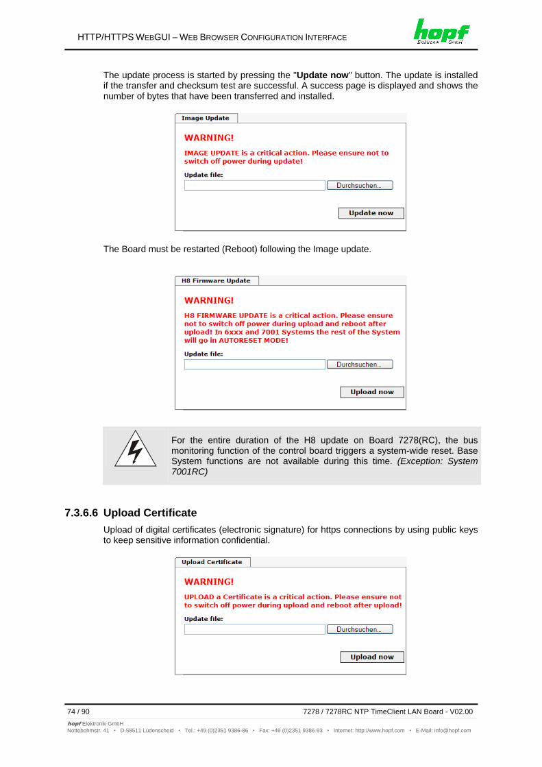
HTTP/HTTPS WEBGUI – WEB BROWSER CONFIGURATION INTERFACE
74 / 90 7278 / 7278RC NTP TimeClient LAN Board - V02.00
hopf Elektronik GmbH
Nottebohmstr. 41 • D-58511 Lüdenscheid • Tel.: +49 (0)2351 9386-86 • Fax: +49 (0)2351 9386-93 • Internet: http://www.hopf.com • E-Mail: [email protected]
The update process is started by pressing the "Update now" button. The update is installed if the transfer and checksum test are successful. A success page is displayed and shows the number of bytes that have been transferred and installed.
The Board must be restarted (Reboot) following the Image update.
For the entire duration of the H8 update on Board 7278(RC), the bus monitoring function of the control board triggers a system-wide reset. Base System functions are not available during this time. (Exception: System 7001RC)
7.3.6.6 Upload Certificate
Upload of digital certificates (electronic signature) for https connections by using public keys to keep sensitive information confidential.
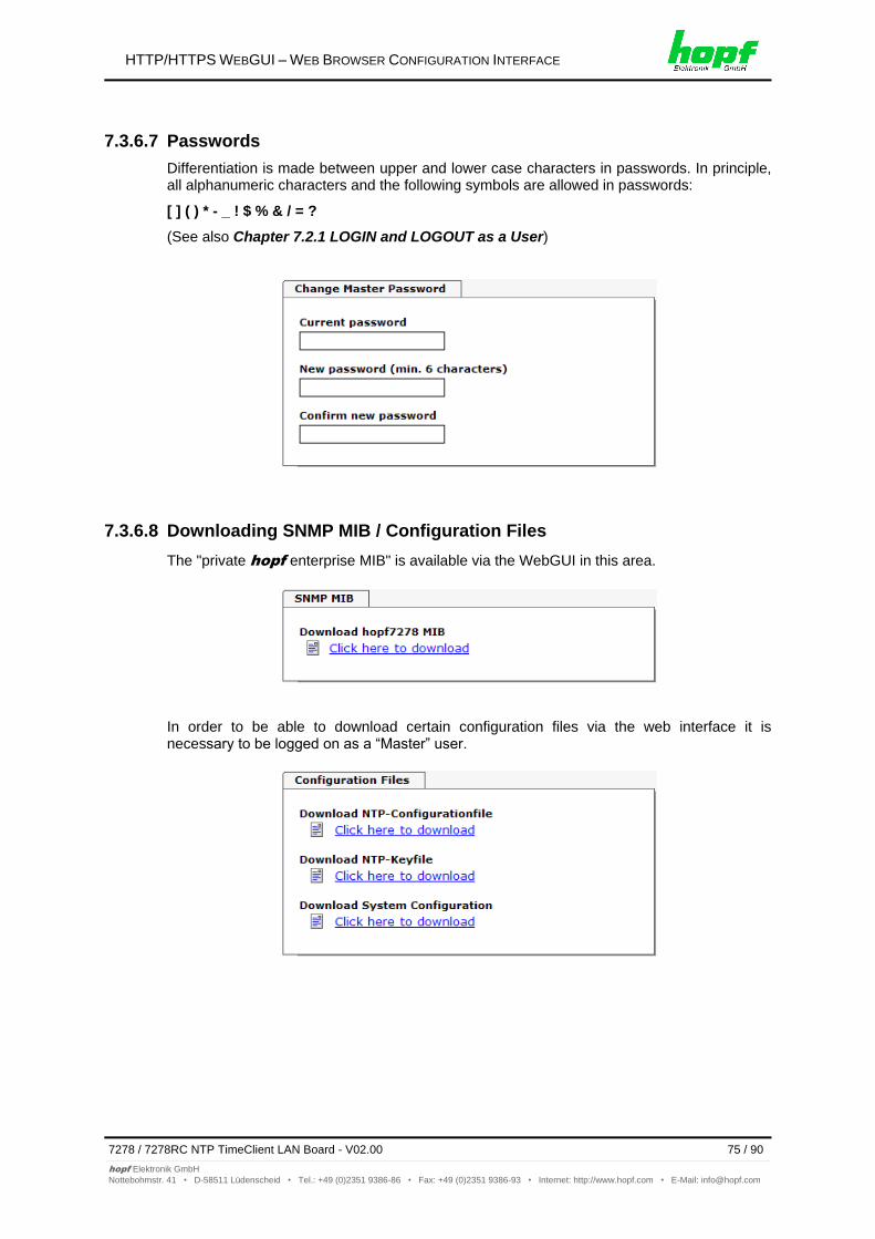
HTTP/HTTPS WEBGUI – WEB BROWSER CONFIGURATION INTERFACE
7278 / 7278RC NTP TimeClient LAN Board - V02.00 75 / 90
hopf Elektronik GmbH
Nottebohmstr. 41 • D-58511 Lüdenscheid • Tel.: +49 (0)2351 9386-86 • Fax: +49 (0)2351 9386-93 • Internet: http://www.hopf.com • E-Mail: [email protected]
7.3.6.7 Passwords
Differentiation is made between upper and lower case characters in passwords. In principle, all alphanumeric characters and the following symbols are allowed in passwords:
[ ] ( ) * - _ ! $ % & / = ?
(See also Chapter 7.2.1 LOGIN and LOGOUT as a User)
7.3.6.8 Downloading SNMP MIB / Configuration Files
The "private hopf enterprise MIB" is available via the WebGUI in this area.
In order to be able to download certain configuration files via the web interface it is necessary to be logged on as a “Master” user.
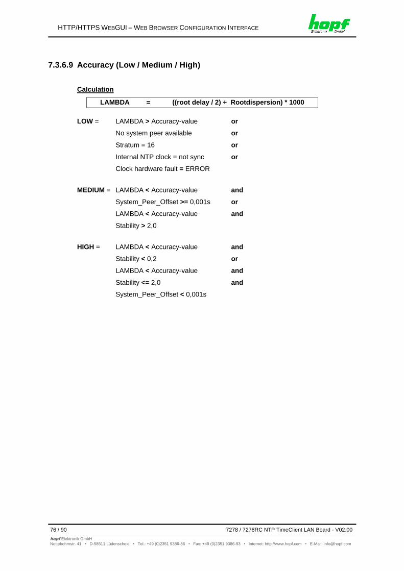
HTTP/HTTPS WEBGUI – WEB BROWSER CONFIGURATION INTERFACE
76 / 90 7278 / 7278RC NTP TimeClient LAN Board - V02.00
hopf Elektronik GmbH
Nottebohmstr. 41 • D-58511 Lüdenscheid • Tel.: +49 (0)2351 9386-86 • Fax: +49 (0)2351 9386-93 • Internet: http://www.hopf.com • E-Mail: [email protected]
7.3.6.9 Accuracy (Low / Medium / High)
Calculation
LAMBDA = ((root delay / 2) + Rootdispersion) * 1000
LOW = LAMBDA > Accuracy-value or
No system peer available or
Stratum = 16 or
Internal NTP clock = not sync or
Clock hardware fault = ERROR
MEDIUM = LAMBDA < Accuracy-value and
System_Peer_Offset >= 0,001s or
LAMBDA < Accuracy-value and
Stability > 2,0
HIGH = LAMBDA < Accuracy-value and
Stability < 0,2 or
LAMBDA < Accuracy-value and
Stability <= 2,0 and
System_Peer_Offset < 0,001s
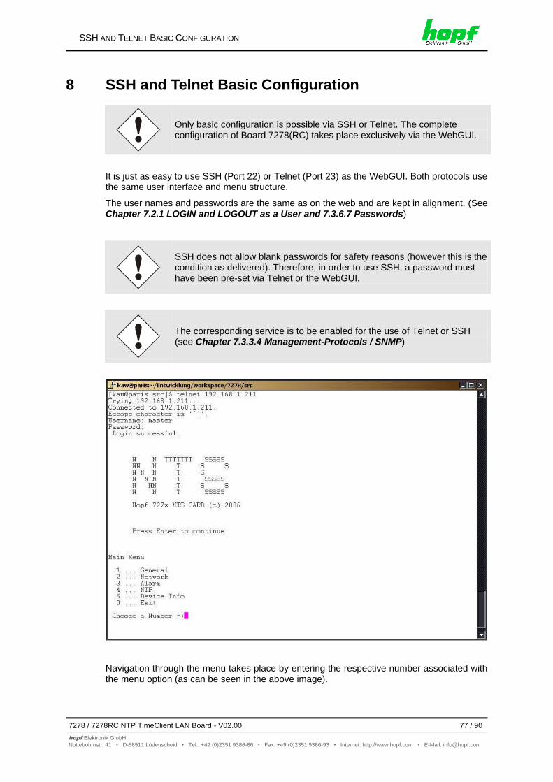
SSH AND TELNET BASIC CONFIGURATION
7278 / 7278RC NTP TimeClient LAN Board - V02.00 77 / 90
hopf Elektronik GmbH
Nottebohmstr. 41 • D-58511 Lüdenscheid • Tel.: +49 (0)2351 9386-86 • Fax: +49 (0)2351 9386-93 • Internet: http://www.hopf.com • E-Mail: [email protected]
8 SSH and Telnet Basic Configuration
Only basic configuration is possible via SSH or Telnet. The complete configuration of Board 7278(RC) takes place exclusively via the WebGUI.
It is just as easy to use SSH (Port 22) or Telnet (Port 23) as the WebGUI. Both protocols use the same user interface and menu structure.
The user names and passwords are the same as on the web and are kept in alignment. (See Chapter 7.2.1 LOGIN and LOGOUT as a User and 7.3.6.7 Passwords)
SSH does not allow blank passwords for safety reasons (however this is the condition as delivered). Therefore, in order to use SSH, a password must have been pre-set via Telnet or the WebGUI.
The corresponding service is to be enabled for the use of Telnet or SSH (see Chapter 7.3.3.4 Management-Protocols / SNMP)
Navigation through the menu takes place by entering the respective number associated with the menu option (as can be seen in the above image).
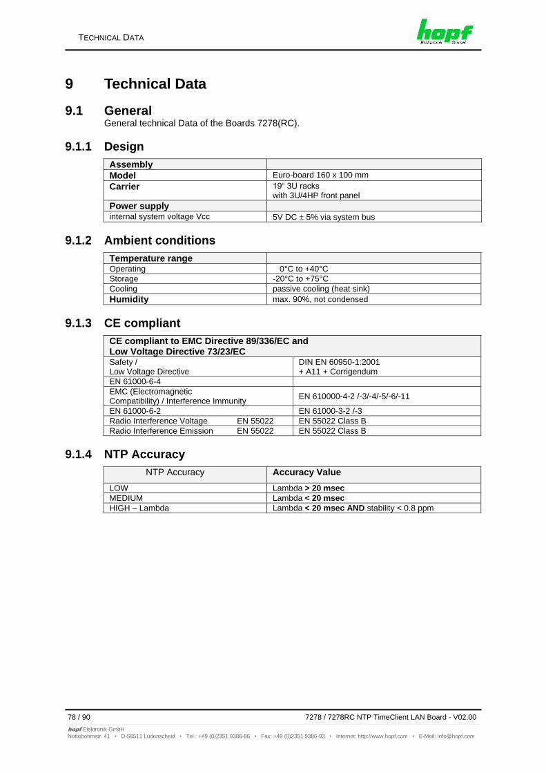
TECHNICAL DATA
78 / 90 7278 / 7278RC NTP TimeClient LAN Board - V02.00
hopf Elektronik GmbH
Nottebohmstr. 41 • D-58511 Lüdenscheid • Tel.: +49 (0)2351 9386-86 • Fax: +49 (0)2351 9386-93 • Internet: http://www.hopf.com • E-Mail: [email protected]
9 Technical Data
9.1 General General technical Data of the Boards 7278(RC).
9.1.1 Design
Assembly
Model Euro-board 160 x 100 mm
Carrier 19“ 3U racks with 3U/4HP front panel
Power supply internal system voltage Vcc 5V DC 5% via system bus
9.1.2 Ambient conditions
Temperature range Operating 0°C to +40°C
Storage -20°C to +75°C
Cooling passive cooling (heat sink)
Humidity max. 90%, not condensed
9.1.3 CE compliant
CE compliant to EMC Directive 89/336/EC and Low Voltage Directive 73/23/EC Safety / Low Voltage Directive
DIN EN 60950-1:2001 + A11 + Corrigendum
EN 61000-6-4
EMC (Electromagnetic Compatibility) / Interference Immunity
EN 610000-4-2 /-3/-4/-5/-6/-11
EN 61000-6-2 EN 61000-3-2 /-3
Radio Interference Voltage EN 55022 EN 55022 Class B
Radio Interference Emission EN 55022 EN 55022 Class B
9.1.4 NTP Accuracy
NTP Accuracy Accuracy Value
LOW Lambda > 20 msec
MEDIUM Lambda < 20 msec
HIGH – Lambda Lambda < 20 msec AND stability < 0.8 ppm
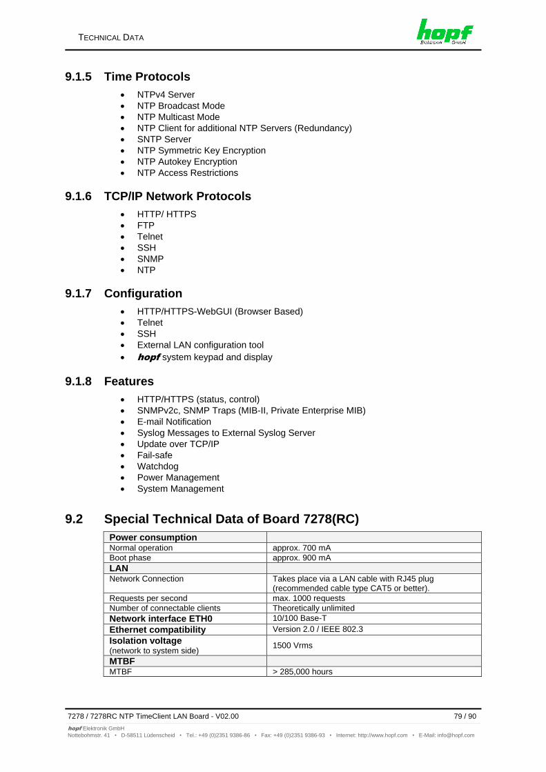
TECHNICAL DATA
7278 / 7278RC NTP TimeClient LAN Board - V02.00 79 / 90
hopf Elektronik GmbH
Nottebohmstr. 41 • D-58511 Lüdenscheid • Tel.: +49 (0)2351 9386-86 • Fax: +49 (0)2351 9386-93 • Internet: http://www.hopf.com • E-Mail: [email protected]
9.1.5 Time Protocols
NTPv4 Server
NTP Broadcast Mode
NTP Multicast Mode
NTP Client for additional NTP Servers (Redundancy)
SNTP Server
NTP Symmetric Key Encryption
NTP Autokey Encryption
NTP Access Restrictions
9.1.6 TCP/IP Network Protocols
HTTP/ HTTPS
FTP
Telnet
SSH
SNMP
NTP
9.1.7 Configuration
HTTP/HTTPS-WebGUI (Browser Based)
Telnet
SSH
External LAN configuration tool
hopf system keypad and display
9.1.8 Features
HTTP/HTTPS (status, control)
SNMPv2c, SNMP Traps (MIB-II, Private Enterprise MIB)
E-mail Notification
Syslog Messages to External Syslog Server
Update over TCP/IP
Fail-safe
Watchdog
Power Management
System Management
9.2 Special Technical Data of Board 7278(RC)
Power consumption Normal operation approx. 700 mA
Boot phase approx. 900 mA
LAN Network Connection Takes place via a LAN cable with RJ45 plug
(recommended cable type CAT5 or better).
Requests per second max. 1000 requests
Number of connectable clients Theoretically unlimited
Network interface ETH0 10/100 Base-T
Ethernet compatibility Version 2.0 / IEEE 802.3
Isolation voltage (network to system side)
1500 Vrms
MTBF MTBF > 285,000 hours
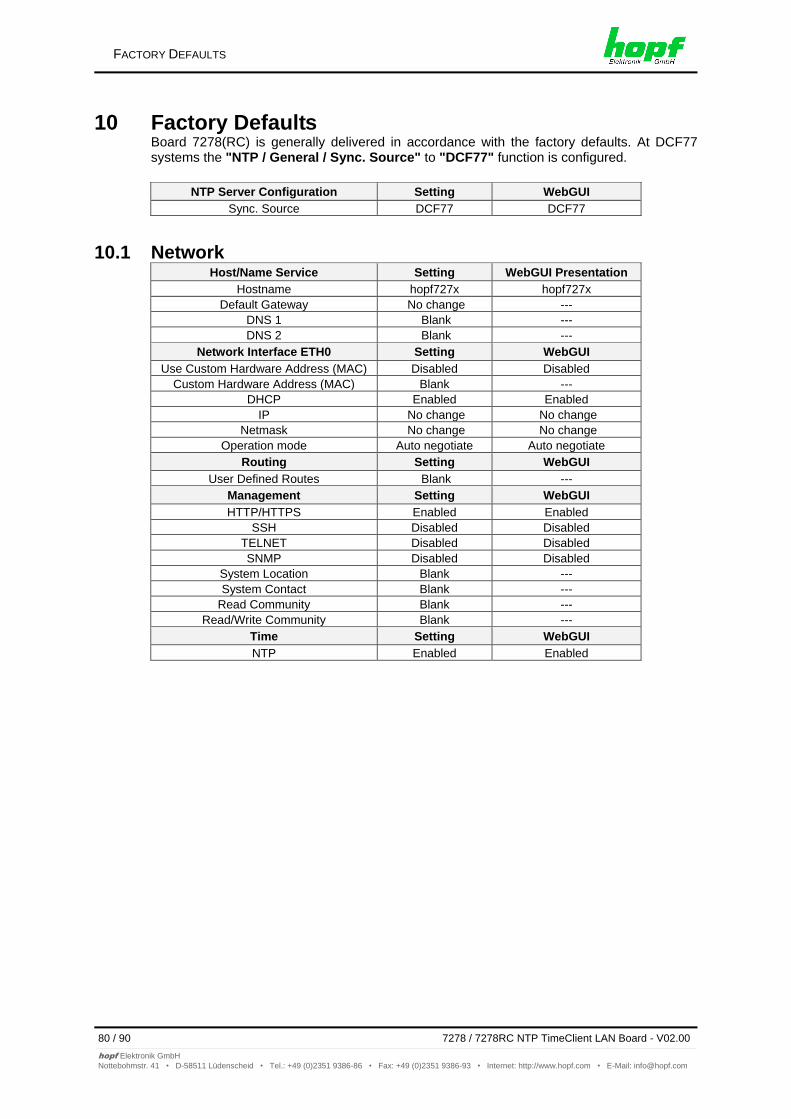
FACTORY DEFAULTS
80 / 90 7278 / 7278RC NTP TimeClient LAN Board - V02.00
hopf Elektronik GmbH
Nottebohmstr. 41 • D-58511 Lüdenscheid • Tel.: +49 (0)2351 9386-86 • Fax: +49 (0)2351 9386-93 • Internet: http://www.hopf.com • E-Mail: [email protected]
10 Factory Defaults Board 7278(RC) is generally delivered in accordance with the factory defaults. At DCF77 systems the "NTP / General / Sync. Source" to "DCF77" function is configured.
NTP Server Configuration Setting WebGUI
Sync. Source DCF77 DCF77
10.1 Network Host/Name Service Setting WebGUI Presentation
Hostname hopf727x hopf727x
Default Gateway No change ---
DNS 1 Blank ---
DNS 2 Blank ---
Network Interface ETH0 Setting WebGUI
Use Custom Hardware Address (MAC) Disabled Disabled
Custom Hardware Address (MAC) Blank ---
DHCP Enabled Enabled
IP No change No change
Netmask No change No change
Operation mode Auto negotiate Auto negotiate
Routing Setting WebGUI
User Defined Routes Blank ---
Management Setting WebGUI
HTTP/HTTPS Enabled Enabled
SSH Disabled Disabled TELNET Disabled Disabled SNMP Disabled Disabled
System Location Blank ---
System Contact Blank ---
Read Community Blank ---
Read/Write Community Blank ---
Time Setting WebGUI
NTP Enabled Enabled
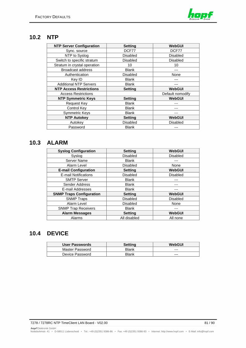
FACTORY DEFAULTS
7278 / 7278RC NTP TimeClient LAN Board - V02.00 81 / 90
hopf Elektronik GmbH
Nottebohmstr. 41 • D-58511 Lüdenscheid • Tel.: +49 (0)2351 9386-86 • Fax: +49 (0)2351 9386-93 • Internet: http://www.hopf.com • E-Mail: [email protected]
10.2 NTP
NTP Server Configuration Setting WebGUI
Sync. source DCF77 DCF77
NTP to Syslog Disabled Disabled
Switch to specific stratum Disabled Disabled
Stratum in crystal operation 10 10
Broadcast address Blank ---
Authentication Disabled None
Key ID Blank ---
Additional NTP Servers Blank ---
NTP Access Restrictions Setting WebGUI
Access Restrictions Default nomodify
NTP Symmetric Keys Setting WebGUI
Request Key Blank ---
Control Key Blank ---
Symmetric Keys Blank ---
NTP Autokey Setting WebGUI
Autokey Disabled Disabled
Password Blank ---
10.3 ALARM
Syslog Configuration Setting WebGUI
Syslog Disabled Disabled
Server Name Blank ---
Alarm Level Disabled None
E-mail Configuration Setting WebGUI
E-mail Notifications Disabled Disabled
SMTP Server Blank ---
Sender Address Blank ---
E-mail Addresses Blank ---
SNMP Traps Configuration Setting WebGUI
SNMP Traps Disabled Disabled
Alarm Level Disabled None
SNMP Trap Receivers Blank ---
Alarm Messages Setting WebGUI
Alarms All disabled All none
10.4 DEVICE
User Passwords Setting WebGUI
Master Password Blank ---
Device Password Blank ---
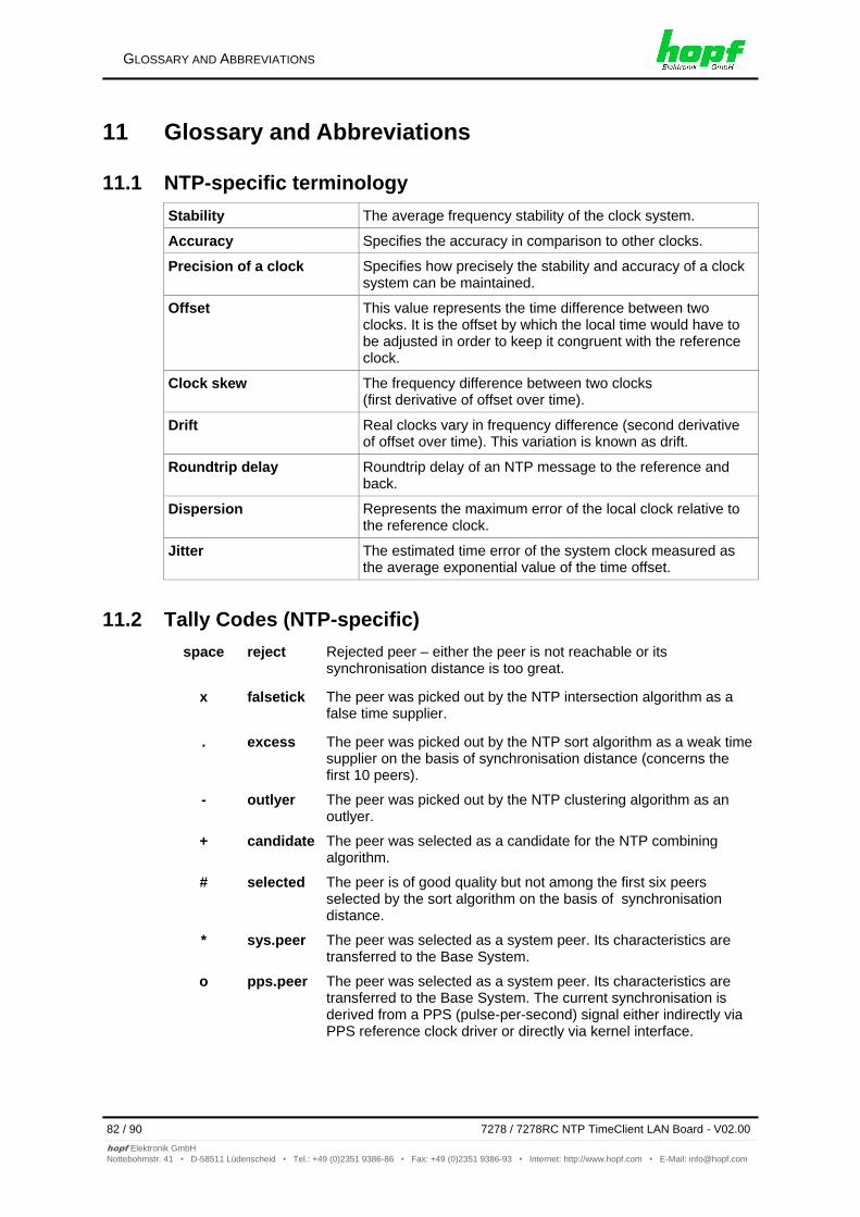
GLOSSARY AND ABBREVIATIONS
82 / 90 7278 / 7278RC NTP TimeClient LAN Board - V02.00
hopf Elektronik GmbH
Nottebohmstr. 41 • D-58511 Lüdenscheid • Tel.: +49 (0)2351 9386-86 • Fax: +49 (0)2351 9386-93 • Internet: http://www.hopf.com • E-Mail: [email protected]
11 Glossary and Abbreviations
11.1 NTP-specific terminology
Stability The average frequency stability of the clock system.
Accuracy Specifies the accuracy in comparison to other clocks.
Precision of a clock
Specifies how precisely the stability and accuracy of a clock system can be maintained.
Offset This value represents the time difference between two clocks. It is the offset by which the local time would have to be adjusted in order to keep it congruent with the reference clock.
Clock skew The frequency difference between two clocks (first derivative of offset over time).
Drift Real clocks vary in frequency difference (second derivative of offset over time). This variation is known as drift.
Roundtrip delay Roundtrip delay of an NTP message to the reference and back.
Dispersion Represents the maximum error of the local clock relative to the reference clock.
Jitter The estimated time error of the system clock measured as the average exponential value of the time offset.
11.2 Tally Codes (NTP-specific)
space reject Rejected peer – either the peer is not reachable or its synchronisation distance is too great.
x falsetick The peer was picked out by the NTP intersection algorithm as a false time supplier.
. excess The peer was picked out by the NTP sort algorithm as a weak time supplier on the basis of synchronisation distance (concerns the first 10 peers).
- outlyer The peer was picked out by the NTP clustering algorithm as an outlyer.
+ candidate The peer was selected as a candidate for the NTP combining algorithm.
# selected The peer is of good quality but not among the first six peers selected by the sort algorithm on the basis of synchronisation distance.
* sys.peer The peer was selected as a system peer. Its characteristics are transferred to the Base System.
o pps.peer The peer was selected as a system peer. Its characteristics are transferred to the Base System. The current synchronisation is derived from a PPS (pulse-per-second) signal either indirectly via PPS reference clock driver or directly via kernel interface.
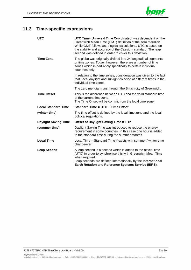
GLOSSARY AND ABBREVIATIONS
7278 / 7278RC NTP TimeClient LAN Board - V02.00 83 / 90
hopf Elektronik GmbH
Nottebohmstr. 41 • D-58511 Lüdenscheid • Tel.: +49 (0)2351 9386-86 • Fax: +49 (0)2351 9386-93 • Internet: http://www.hopf.com • E-Mail: [email protected]
11.3 Time-specific expressions
UTC UTC Time (Universal Time Coordinated) was dependent on the Greenwich Mean Time (GMT) definition of the zero meridian. While GMT follows astrological calculations, UTC is based on the stability and accuracy of the Caesium standard. The leap second was defined in order to cover this deviation.
Time Zone The globe was originally divided into 24 longitudinal segments or time zones. Today, however, there are a number of time zones which in part apply specifically to certain individual countries only.
In relation to the time zones, consideration was given to the fact that local daylight and sunlight coincide at different times in the individual time zones.
The zero meridian runs through the British city of Greenwich.
Time Offset
This is the difference between UTC and the valid standard time of the current time zone. The Time Offset will be commit from the local time zone.
Local Standard Time
(winter time)
Standard Time = UTC + Time Offset
The time offset is defined by the local time zone and the local political regulations.
Daylight Saving Time
(summer time)
Offset of Daylight Saving Time = + 1h
Daylight Saving Time was introduced to reduce the energy requirement in some countries. In this case one hour is added to the standard time during the summer months.
Local Time Local Time = Standard Time if exists with summer / winter time changeover
Leap Second A leap second is a second which is added to the official time (UTC) in order to synchronise this with Greenwich Mean Time when required. Leap seconds are defined internationally by the International Earth Rotation and Reference Systems Service (IERS).
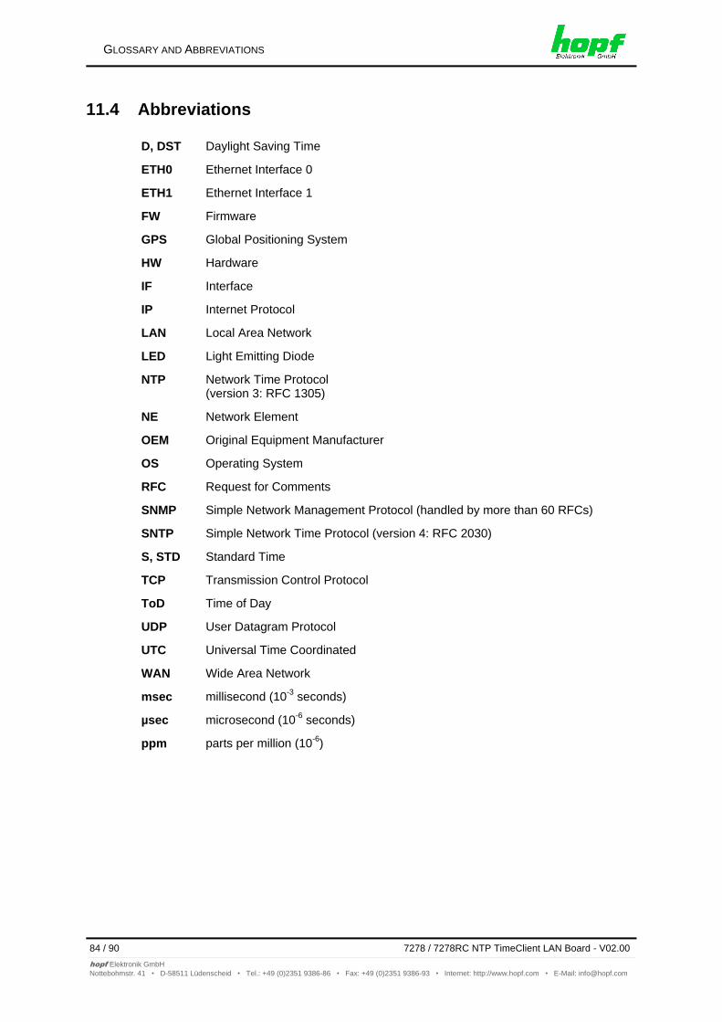
GLOSSARY AND ABBREVIATIONS
84 / 90 7278 / 7278RC NTP TimeClient LAN Board - V02.00
hopf Elektronik GmbH
Nottebohmstr. 41 • D-58511 Lüdenscheid • Tel.: +49 (0)2351 9386-86 • Fax: +49 (0)2351 9386-93 • Internet: http://www.hopf.com • E-Mail: [email protected]
11.4 Abbreviations
D, DST Daylight Saving Time
ETH0 Ethernet Interface 0
ETH1 Ethernet Interface 1
FW Firmware
GPS Global Positioning System
HW Hardware
IF Interface
IP Internet Protocol
LAN Local Area Network
LED Light Emitting Diode
NTP Network Time Protocol (version 3: RFC 1305)
NE Network Element
OEM Original Equipment Manufacturer
OS Operating System
RFC Request for Comments
SNMP Simple Network Management Protocol (handled by more than 60 RFCs)
SNTP Simple Network Time Protocol (version 4: RFC 2030)
S, STD Standard Time
TCP Transmission Control Protocol
ToD Time of Day
UDP User Datagram Protocol
UTC Universal Time Coordinated
WAN Wide Area Network
msec millisecond (10-3
seconds)
µsec microsecond (10-6
seconds)
ppm parts per million (10-6
)
GLOSSARY AND ABBREVIATIONS
7278 / 7278RC NTP TimeClient LAN Board - V02.00 85 / 90
hopf Elektronik GmbH
Nottebohmstr. 41 • D-58511 Lüdenscheid • Tel.: +49 (0)2351 9386-86 • Fax: +49 (0)2351 9386-93 • Internet: http://www.hopf.com • E-Mail: [email protected]
11.5 Definitions
An explanation of the terms used in this document.
11.5.1 DHCP (Dynamic Host Configuration Protocol)
DHCP makes it possible to integrate a new computer into an existing network with no additional configuration. It is necessary only to set the automatic reference of the IP address on the client. Without DHCP, relatively complex settings need to be made. In addition to setting the IP address, other parameters such as network mask, gateway and DNS server would need to be entered. A DHCP server can assign these parameters automatically by DHCP when starting up a new computer (DHCP client).
DHCP is an extension of the BOOTP protocol. A valid IP address is allocated automatically if a DHCP server is available on the network and DHCP is enabled.
The Board is supplied from the factory with DHCP enabled.
See RFC 2131 Dynamic Host Configuration Protocol for further information
11.5.2 NTP (Network Time Protocol)
Network Time Protocol (NTP) is a standard for the synchronisation of clocks in computer systems over packet-based communication networks. Although it is processed mainly over UDP, it can also be transported by other layer 4 protocols such as TCP. It was specially developed to facilitate reliable timing via networks with variable roundtrip times.
NTP uses the Marzullo algorithm (devised by Keith Marzullo of San Diego University in his dissertation) with a UTC timescale and which supports leap seconds from Version 4.0. NTP. It is one of the oldest TCP/IP protocols still in use. It was developed by David Mills of the University of Delaware and published in 1985. The protocol and UNIX implementation continue to be developed under his direction. Version 4 is the up to date version of the protocol. This uses UDP Port 123.
NTPv4 can maintain the local time of a system to an accuracy of some 10 milliseconds via the public Internet. Accuracies of 500 microseconds and better are possible under ideal conditions in local networks.
With a sufficiently stable, local clock generator (oven-stabilised quartz, rubidium oscillator, etc.) and using the kernel PLL (see above), the phase error between reference clock generator and local clock can be reduced to something of the order of a few hundred microseconds. NTP automatically compensates for the drift of the local clock.
NTP can be installed over firewalls and offers a range of security functions.
See RFC 1305 for further information.
GLOSSARY AND ABBREVIATIONS
86 / 90 7278 / 7278RC NTP TimeClient LAN Board - V02.00
hopf Elektronik GmbH
Nottebohmstr. 41 • D-58511 Lüdenscheid • Tel.: +49 (0)2351 9386-86 • Fax: +49 (0)2351 9386-93 • Internet: http://www.hopf.com • E-Mail: [email protected]
11.5.3 SNMP (Simple Network Management Protocol)
Simple Network Management Protocol (SNMP) is a network protocol which was developed by the IETF in order to be able to monitor and control network elements from a central station. This protocol regulates the communication between the monitored devices and the monitoring station. SNMP describes the composition of the data packets which can be transmitted and the communication procedure. SNMP was designed in such a way that every network-compatible device can be monitored. The network management tasks which are possible with SNMP include:
Monitoring of network components
Remote control and configuration of network components.
Fault detection and notification
Due to its simplicity, SNMP has become the standard which is supported by most management programmes. SNMP Versions 1 and 2c offer hardly any safety mechanisms. The safety mechanisms have been significantly expanded in the current Version 3.
With the aid of description files known as MIB’s (Management Information Base), the management programmes are in a position to represent the hierarchical structure of the data of any desired SNMP agent and to request data from them. In addition to the MIB’s defined in the RFC’s, every software and hardware manufacturer can define his own so-called private MIB’s, which reflect the special characteristics of his product.
11.5.4 TCP/IP (Transmission Control Protocol / Internet Protocol)
TCP and IP are generally used concurrently and thus the term TCP/IP has become established as the standard for both protocols.
IP is based on network layer 3 (layer 3) in the OSI Layer Model while TCP is based on layer 4, the transport layer. In other words, the expression TCP/IP signifies network communication in which the TCP transport mechanism is used to distribute or deliver data over IP networks. As a simple example: Web browsers use TCP/IP to communicate with web servers.
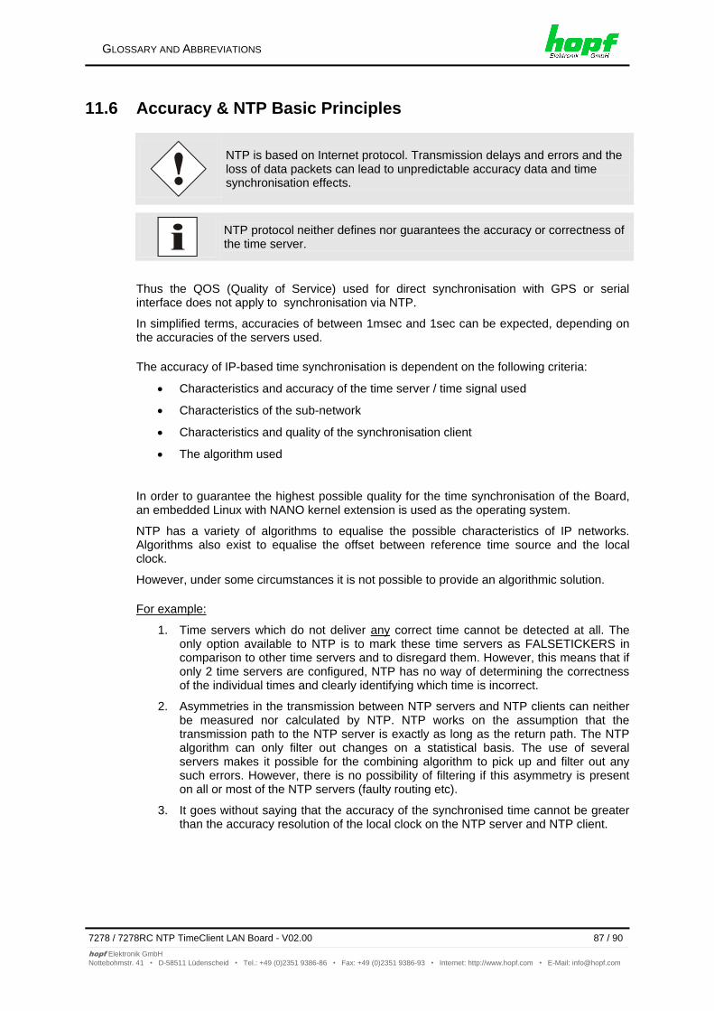
GLOSSARY AND ABBREVIATIONS
7278 / 7278RC NTP TimeClient LAN Board - V02.00 87 / 90
hopf Elektronik GmbH
Nottebohmstr. 41 • D-58511 Lüdenscheid • Tel.: +49 (0)2351 9386-86 • Fax: +49 (0)2351 9386-93 • Internet: http://www.hopf.com • E-Mail: [email protected]
11.6 Accuracy & NTP Basic Principles
NTP is based on Internet protocol. Transmission delays and errors and the loss of data packets can lead to unpredictable accuracy data and time synchronisation effects.
NTP protocol neither defines nor guarantees the accuracy or correctness of the time server.
Thus the QOS (Quality of Service) used for direct synchronisation with GPS or serial interface does not apply to synchronisation via NTP.
In simplified terms, accuracies of between 1msec and 1sec can be expected, depending on the accuracies of the servers used.
The accuracy of IP-based time synchronisation is dependent on the following criteria:
Characteristics and accuracy of the time server / time signal used
Characteristics of the sub-network
Characteristics and quality of the synchronisation client
The algorithm used
In order to guarantee the highest possible quality for the time synchronisation of the Board, an embedded Linux with NANO kernel extension is used as the operating system.
NTP has a variety of algorithms to equalise the possible characteristics of IP networks. Algorithms also exist to equalise the offset between reference time source and the local clock.
However, under some circumstances it is not possible to provide an algorithmic solution.
For example:
1. Time servers which do not deliver any correct time cannot be detected at all. The only option available to NTP is to mark these time servers as FALSETICKERS in comparison to other time servers and to disregard them. However, this means that if only 2 time servers are configured, NTP has no way of determining the correctness of the individual times and clearly identifying which time is incorrect.
2. Asymmetries in the transmission between NTP servers and NTP clients can neither be measured nor calculated by NTP. NTP works on the assumption that the transmission path to the NTP server is exactly as long as the return path. The NTP algorithm can only filter out changes on a statistical basis. The use of several servers makes it possible for the combining algorithm to pick up and filter out any such errors. However, there is no possibility of filtering if this asymmetry is present on all or most of the NTP servers (faulty routing etc).
3. It goes without saying that the accuracy of the synchronised time cannot be greater than the accuracy resolution of the local clock on the NTP server and NTP client.
GLOSSARY AND ABBREVIATIONS
88 / 90 7278 / 7278RC NTP TimeClient LAN Board - V02.00
hopf Elektronik GmbH
Nottebohmstr. 41 • D-58511 Lüdenscheid • Tel.: +49 (0)2351 9386-86 • Fax: +49 (0)2351 9386-93 • Internet: http://www.hopf.com • E-Mail: [email protected]
With reference to the above mentioned error circumstances, the delivered time offset of the NTP should be considered to be at best the most favourable case and in no way to be a value that takes account of all possible errors.
In order to resolve this problem, NTP delivers the maximum possible error in relation to the offset. This value is designated as the synchronisation distance ("LAMBDA") and is the sum of the Root Dispersion and half of the Root Delay of all NTP servers used. This value describes the worst possible case and thus the maximum error that can be expected.
For further information see Appendix H (Analysis of Errors and Correctness Principles) of RFC1305 [1].
Finally, please note that the user of the Board is responsible for the network conditions between the Board and the NTP clients.
As an example, we mention the case where a network has a delay of 500msec and an accuracy shift (asynchronisation.) of 50msec occurs. The synchronised clients will therefore NEVER achieve accuracy values of one millisecond or even microseconds!
The accuracy value in the GENERAL tab of the web interface is designed to help the user to estimate the accuracy.
GPS signal sources with radio-synchronous synchronisation status:
Lambda Accuracy
LOW > 15 msec
MEDIUM < 15 msec
HIGH < 15msec AND Stability < 0.05 ppm
DCF77 signal sources with radio-synchronous synchronisation status:
Lambda Accuracy
LOW > 15 msec
MEDIUM < 15 msec
HIGH < 15msec AND Stability < 0.3 ppm
Other signal sources with quartz synchronisation status, configured with additional NTP servers:
Lambda Accuracy
LOW > 15 msec
MEDIUM < 15 msec
HIGH < 15msec AND Stability < 0.8 ppm
LIST OF RFCS
7278 / 7278RC NTP TimeClient LAN Board - V02.00 89 / 90
hopf Elektronik GmbH
Nottebohmstr. 41 • D-58511 Lüdenscheid • Tel.: +49 (0)2351 9386-86 • Fax: +49 (0)2351 9386-93 • Internet: http://www.hopf.com • E-Mail: [email protected]
12 List of RFCs
IPv4: Dynamic Host Configuration Protocol - DHCP (RFC 2131)
Network Time Protocol (NTP): NTP v2 (RFC 1119), NTP v3 (RFC 1305), NTP v4 (no RFC)
Symmetric Key and Autokey Authentication
Simple Network Time Protocol (SNTP): SNTP v3 (RFC 1769), SNTP v4 (RFC 2030)
Time Protocol (TIME): Time Protocol (RFC 868)
Daytime Protocol (DAYTIME): Daytime Protocol (RFC 867)
Hypertext Transfer Protocol (HTTP): HTTP/HTTPS (RC 2616)
Secure Shell (SSH): SSH v1.3, SSH v1.5, SSH v2 (OpenSSH)
Telnet: (RFC 854-RFC 861)
Simple Network Management Protocol (SNMP): SNMPv1 (RFC 1157), SNMPv2c (RFC 1901-1908)
Simple Mail Transfer Protocol ( RFC 2821)
LIST OF OPEN SOURCE PACKAGES USED
90 / 90 7278 / 7278RC NTP TimeClient LAN Board - V02.00
hopf Elektronik GmbH
Nottebohmstr. 41 • D-58511 Lüdenscheid • Tel.: +49 (0)2351 9386-86 • Fax: +49 (0)2351 9386-93 • Internet: http://www.hopf.com • E-Mail: [email protected]
13 List of Open Source Packages used
boa-0.94.13.tar.gz
busybox-1.00-pre5.tar.bz2
e100-2.3.43.tar.gz
ethtool-3.tar.gz
gmp-4.1.2.tar.bz2
liboop-1.0.tar.gz
linux-2.4.21.tar.bz2
lsh-1.5.3.tar.gz
mini_httpd-1.19.tar.gz
mtd-snapshot-20040303.tar.bz2
net-snmp-5.2.1.2.tar.gz
ntp-4.2.0.tar.gz
openssl-0.9.6l.tar.gz
passwd.tar.gz
PPSkit-2.1.2.tar.bz2
smc91111.tar.bz2
sysklogd-1.4.1.tar.gz
tinylogin-1.4.tar.bz2
uClibc-0.9.26.tar.bz2
udhcp-0.9.8.tar.gz
zlib-1.2.1.tar.bz2