
NSRP National Shipbuilding Research Program · NSRP National Shipbuilding Research Program...
17
National Shipbuilding Research Program NSRP DISTRIBUTION STATEMENT 3D Vision for Welder Training and Production Welding March, 2017 Charleston, SC
Transcript of NSRP National Shipbuilding Research Program · NSRP National Shipbuilding Research Program...
National Shipbuilding Research ProgramNSRP
DISTRIBUTION STATEMENT
3D Vision for
Welder Training
and Production Welding
March, 2017
Charleston, SC

Agenda
• Summary of Project / Goals
• Progress
• Plan Forward
Project Team
• Anna Bourdais, Workforce Dev. Panel Chairwoman• Ingalls Shipbuilding,
• Frances Pearce, NSRP Program Manager• ATI,
• James S. Williford, Program Technical Officer• Ingalls Shipbuilding,
• Steven Edelson, Prime Contractor• Visible Welding
Project Overview
• Create a stereo weld video system to add depth-perception to weld-by-camera
• Test usefulness for weld training.
• Test usefulness for recruiting students.
• Test usefulness for mirror (blind) welding.

Goals• Improve training by giving students a new tool and
“aha” welding insights.
• Incrementally recruit “on-the-fence” students with modern VR-like technology.
• Improve blind-welding to shorten shipyard repair times and improve quality.

Depth Perception Comes fromStereo Cameras and 3D Goggles
• Each independent video goes to one eye of the goggles
Stereo VR Goggles
StereoWeld Cameras
Image Processing
Image Processing
Phases• Phase I: Enhanced Student Workstation
• Design, build stereo weld camera system for students.
• In-use testing of the 3D effect.
• Preliminary evaluation and improvement recommendations
• Phase II: Updated system for further testing• Update first system with improvements
• Create second system, if needed
• In-use testing and evaluation
• Conclusions and recommendations

Overall Schedule• Q1, 2017 Implement stereo camera
hardware and software
• Q2 * Complete software* Integrate first system
• Q3 (phase 2) * Field Testing* 2nd system
• Q4 Reporting and Tech transfer.

Stereo Camera Fixture• Two Cameras with Lens sub-assemblies
• Electronics
• 2 Lens controllers
• Exposure synchronization
• USB hub and power
• Thumb adjustments
• Camera spacing and Convergence angles

Camera Modules are derived from V2016-Z Camera
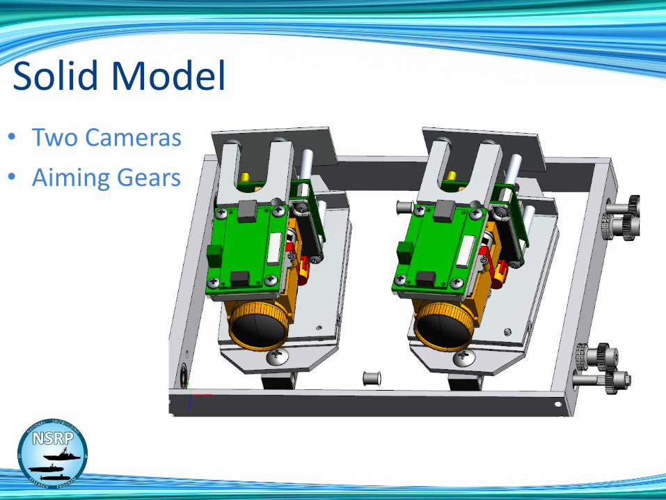
• Two Cameras
• Aiming Gears
Solid Model
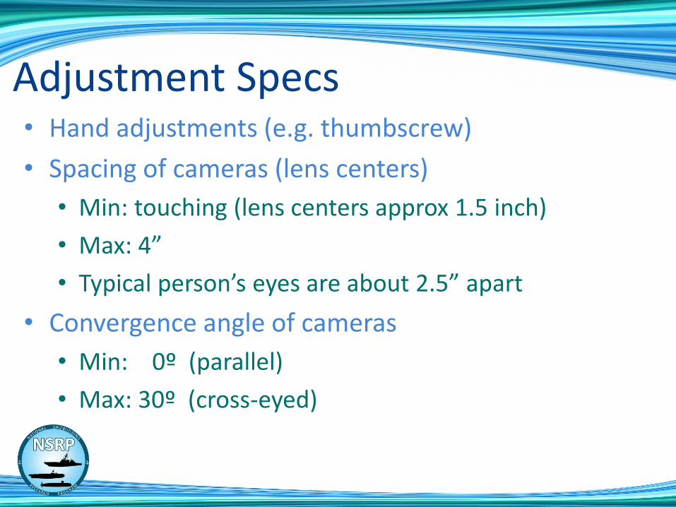
Adjustment Specs• Hand adjustments (e.g. thumbscrew)
• Spacing of cameras (lens centers)
• Min: touching (lens centers approx 1.5 inch)
• Max: 4”
• Typical person’s eyes are about 2.5” apart
• Convergence angle of cameras
• Min: 0º (parallel)
• Max: 30º (cross-eyed)

Stereo Camera Lenses Must be Adjusted Identically
• We must match/track Zoom and Focus
• Zoom and Focus use stepper motors to allow repeatability
• Fixture with special software measuring lenses to build focus/zoom curves
• Create a focus/zoom database.

Zoom - Focus Fixture• Targets spaced at known distances
• Semi-automatic program gathers data

Sample Zoom Focus Curves
0
100
200
300
400
500
600
700
800
900
1000
1 3 5 7 9 11 13 15 17 19 21 23 25 27 29 31 33 35 37 39 41 43 45 47 49 51 53 55 57 59 61 63 65 67
3 in
6 in
9 in
12 in
18 in
24 in
30 in
48 in
60 in
72 in
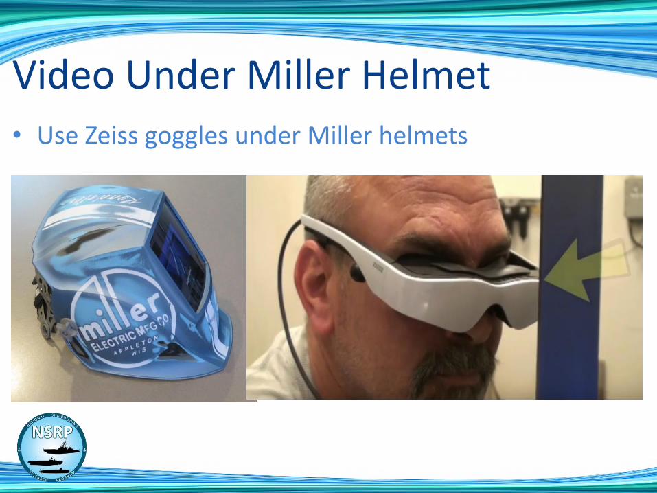
• Use Zeiss goggles under Miller helmets
Video Under Miller Helmet
3D Vision for Welder Training
and Production Welding
NSRP PP 2017- 420
Steven Edelson
Visible Welding


