NS3300 Install GuideWKN file - Fishfinders | Sounders · 4. Northstar NS3300 Pilot System...
32
3 Reference Manual Contents 1 Introduction . . . . . . . . . . . . . . . . . . . . . . . . . . . . . . . . . . . . . . . . . . . . . . . . . . . . . . . . . . .5 1-1 A typical PILOT 3300 system installation . . . . . . . . . . . . . . . . . . . . . 5 1-2 Using the PILOT 3300 system with other instruments. . . . . . . . . . 6 1-2-1 Using other instruments . . . . . . . . . . . . . . . . . . . . . . . . . . . . . . . . . . . . 6 1-2-2 NavBus . . . . . . . . . . . . . . . . . . . . . . . . . . . . . . . . . . . . . . . . . . . . . . . . . . . 6 1-2-3 NMEA . . . . . . . . . . . . . . . . . . . . . . . . . . . . . . . . . . . . . . . . . . . . . . . . . . . . . 7 2 PILOT 3300 system hardware . . . . . . . . . . . . . . . . . . . . . . . . . . . . . . . . . . . . . . . .8 2-1 What comes with your PILOT 3300 system . . . . . . . . . . . . . . . . . . . . 8 2-2 Other parts required . . . . . . . . . . . . . . . . . . . . . . . . . . . . . . . . . . . . . . . 8 3 Installation. . . . . . . . . . . . . . . . . . . . . . . . . . . . . . . . . . . . . . . . . . . . . . . . . . . . . . . . . . . . .9 3-1 Installation sequence . . . . . . . . . . . . . . . . . . . . . . . . . . . . . . . . . . . . . . 9 3-2 Installation guide. . . . . . . . . . . . . . . . . . . . . . . . . . . . . . . . . . . . . . . . . 10 3-2-1 Location guide . . . . . . . . . . . . . . . . . . . . . . . . . . . . . . . . . . . . . . . . . . . .10 3-2-2 Wiring guide . . . . . . . . . . . . . . . . . . . . . . . . . . . . . . . . . . . . . . . . . . . . . .10 3-3 Installing the MCU600 (Main Control Unit) . . . . . . . . . . . . . . . . . . 11 3-4 Installing the power supplies and steering drive . . . . . . . . . . . . . 12 3-4-1 Installing the power supplies . . . . . . . . . . . . . . . . . . . . . . . . . . . . . . .12 3-4-2 Installing the steering drive . . . . . . . . . . . . . . . . . . . . . . . . . . . . . . . .13 3-5 Installing the RFU (rudder feedback unit) . . . . . . . . . . . . . . . . . . . . 17 3-6 Installing the Compass. . . . . . . . . . . . . . . . . . . . . . . . . . . . . . . . . . . . 20 3-7 Installing the Gyro. . . . . . . . . . . . . . . . . . . . . . . . . . . . . . . . . . . . . . . . 22 3-8 Installing the PILOT 3300 display unit and other instruments . .24 4 Dockside setup . . . . . . . . . . . . . . . . . . . . . . . . . . . . . . . . . . . . . . . . . . . . . . . . . . . . . . 27 4-1 Start dockside setup . . . . . . . . . . . . . . . . . . . . . . . . . . . . . . . . . . . . . . 27 4-2 Calibrating the rudder feedback unit. . . . . . . . . . . . . . . . . . . . . . . . 27 5 Sea trials . . . . . . . . . . . . . . . . . . . . . . . . . . . . . . . . . . . . . . . . . . . . . . . . . . . . . . . . . . . . . 28 5-1 Calibrating the compass. . . . . . . . . . . . . . . . . . . . . . . . . . . . . . . . . . . 28 5-2 Aligning the compass and the rudder . . . . . . . . . . . . . . . . . . . . . . . 28 5-2-1 Aligning the compass (Align heading). . . . . . . . . . . . . . . . . . . . . . .28 5-2-2 Aligning the Rudder (Centre rudder) . . . . . . . . . . . . . . . . . . . . . . . .28 Appendix A - Specifications - MCU600 . . . . . . . . . . . . . . . . . . . . . . . . . . . . . . 29 Appendix B - Specifications - NS3300 Display. . . . . . . . . . . . . . . . . . . . . . 30 Appendix C - User data . . . . . . . . . . . . . . . . . . . . . . . . . . . . . . . . . . . . . . . . . . . . . . . 31
Transcript of NS3300 Install GuideWKN file - Fishfinders | Sounders · 4. Northstar NS3300 Pilot System...
3Reference Manual
Contents1 Introduction . . . . . . . . . . . . . . . . . . . . . . . . . . . . . . . . . . . . . . . . . . . . . . . . . . . . . . . . . . .5
1-1 A typical PILOT 3300 system installation . . . . . . . . . . . . . . . . . . . . . 51-2 Using the PILOT 3300 system with other instruments. . . . . . . . . . 6
1-2-1 Using other instruments . . . . . . . . . . . . . . . . . . . . . . . . . . . . . . . . . . . . 61-2-2 NavBus . . . . . . . . . . . . . . . . . . . . . . . . . . . . . . . . . . . . . . . . . . . . . . . . . . . 61-2-3 NMEA . . . . . . . . . . . . . . . . . . . . . . . . . . . . . . . . . . . . . . . . . . . . . . . . . . . . . 7
2 PILOT 3300 system hardware. . . . . . . . . . . . . . . . . . . . . . . . . . . . . . . . . . . . . . . .8
2-1 What comes with your PILOT 3300 system . . . . . . . . . . . . . . . . . . . . 82-2 Other parts required . . . . . . . . . . . . . . . . . . . . . . . . . . . . . . . . . . . . . . . 8
3 Installation. . . . . . . . . . . . . . . . . . . . . . . . . . . . . . . . . . . . . . . . . . . . . . . . . . . . . . . . . . . . .9
3-1 Installation sequence . . . . . . . . . . . . . . . . . . . . . . . . . . . . . . . . . . . . . . 93-2 Installation guide. . . . . . . . . . . . . . . . . . . . . . . . . . . . . . . . . . . . . . . . .10
3-2-1 Location guide . . . . . . . . . . . . . . . . . . . . . . . . . . . . . . . . . . . . . . . . . . . .103-2-2 Wiring guide . . . . . . . . . . . . . . . . . . . . . . . . . . . . . . . . . . . . . . . . . . . . . .10
3-3 Installing the MCU600 (Main Control Unit) . . . . . . . . . . . . . . . . . . 113-4 Installing the power supplies and steering drive . . . . . . . . . . . . . 12
3-4-1 Installing the power supplies . . . . . . . . . . . . . . . . . . . . . . . . . . . . . . .123-4-2 Installing the steering drive . . . . . . . . . . . . . . . . . . . . . . . . . . . . . . . .13
3-5 Installing the RFU (rudder feedback unit) . . . . . . . . . . . . . . . . . . . . 173-6 Installing the Compass. . . . . . . . . . . . . . . . . . . . . . . . . . . . . . . . . . . .203-7 Installing the Gyro. . . . . . . . . . . . . . . . . . . . . . . . . . . . . . . . . . . . . . . .223-8 Installing the PILOT 3300 display unit and other instruments . .24
4 Dockside setup . . . . . . . . . . . . . . . . . . . . . . . . . . . . . . . . . . . . . . . . . . . . . . . . . . . . . . 27
4-1 Start dockside setup . . . . . . . . . . . . . . . . . . . . . . . . . . . . . . . . . . . . . .274-2 Calibrating the rudder feedback unit. . . . . . . . . . . . . . . . . . . . . . . .27
5 Sea trials . . . . . . . . . . . . . . . . . . . . . . . . . . . . . . . . . . . . . . . . . . . . . . . . . . . . . . . . . . . . . 28
5-1 Calibrating the compass. . . . . . . . . . . . . . . . . . . . . . . . . . . . . . . . . . .285-2 Aligning the compass and the rudder. . . . . . . . . . . . . . . . . . . . . . .28
5-2-1 Aligning the compass (Align heading). . . . . . . . . . . . . . . . . . . . . . .285-2-2 Aligning the Rudder (Centre rudder) . . . . . . . . . . . . . . . . . . . . . . . .28
Appendix A - Specifications - MCU600 . . . . . . . . . . . . . . . . . . . . . . . . . . . . . . 29
Appendix B - Specifications - NS3300 Display. . . . . . . . . . . . . . . . . . . . . . 30
Appendix C - User data . . . . . . . . . . . . . . . . . . . . . . . . . . . . . . . . . . . . . . . . . . . . . . . 31
MMoore
Text Box
Note: This document has not been formally checked, it is for reference only.
4 Northstar NS3300 Pilot System Intallation
It is the owner’s sole responsibility to install and use the instrument and transducer/s in a manner that will not cause accidents, personal injury or property damage. The user of this product is solely responsible for observing safe boating practices.
The choice, location, and installation of all components in any autopilot system is critical. If installation is not correct, the unit can not perform at its designed potential. If in doubt, consult your Northstar dealer. Ensure that any holes that cut are in a safe position and will not weaken the boat’s structure. If in doubt, consult a qualified boat builder.
Using the PILOT 3300 system : The PILOT 3300 system is intended as an aid to save a helmsman from having to steer for long periods of
time, not as the main means of steering the boat. The PILOT 3300 system is not intended for use in extreme weather, in adverse conditions or in water near
other boats, dangerous waters or land. The PILOT 3300 system can not control the boat better than a helmsman. In adverse conditions steer the
boat manually. Never leave the helm unattended. Keep a watch at all times. The helmsman should always monitor the
course of the boat and the PILOT 3300 system and be ready to resume steering the boat manually. The performance of the PILOT 3300 system can be affected by the failure of a part, environmental
conditions, improper installation and use.
Northstar DISCLAIMS ALL LIABILITY FOR ANY USE OF THIS PRODUCT IN A WAY THAT MAY CAUSE ACCIDENTS, DAMAGE OR THAT MAY VIOLATE THE LAW.
As Northstar is continuously improving this product we retain the right to make changes to the product at any time which may not be reflected in this version of manual. Please contact your nearest Northstar office if you require any further assistance.
Governing Language: This statement, any instruction manuals, user guides and other information relating to the product (Documentation) may be translated to, or has been translated from, another language (Translation). In the event of any conflict between any Translation of the Documentation, the English language version of the Documentation will be the official version of the Documentation.
Copyright © 2005 Northstar Limited. All rights reserved. Northstar is a registered trademark.
Important
5Reference Manual
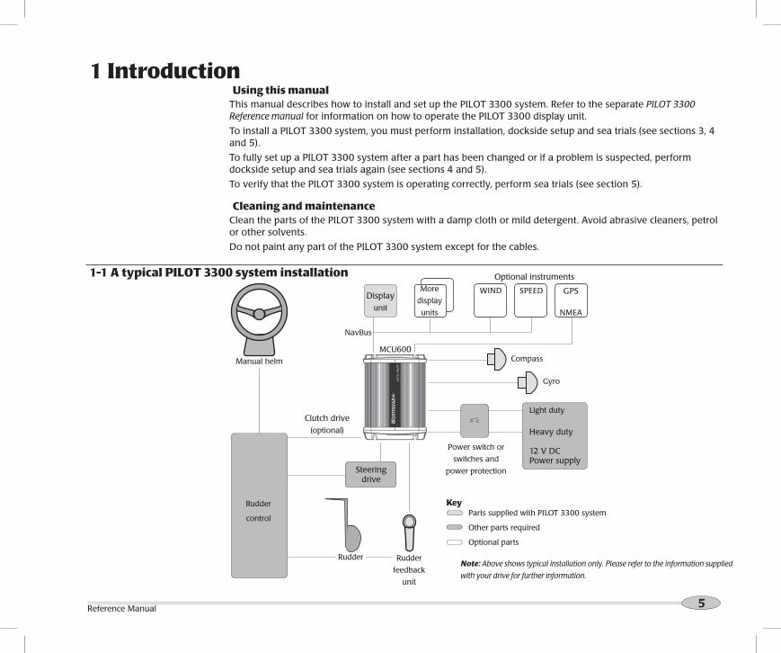
1 IntroductionUsing this manual
This manual describes how to install and set up the PILOT 3300 system. Refer to the separate PILOT 3300 Reference manual for information on how to operate the PILOT 3300 display unit.
To install a PILOT 3300 system, you must perform installation, dockside setup and sea trials (see sections 3, 4 and 5).
To fully set up a PILOT 3300 system after a part has been changed or if a problem is suspected, perform dockside setup and sea trials again (see sections 4 and 5).
To verify that the PILOT 3300 system is operating correctly, perform sea trials (see section 5).
Cleaning and maintenanceClean the parts of the PILOT 3300 system with a damp cloth or mild detergent. Avoid abrasive cleaners, petrol or other solvents.
Do not paint any part of the PILOT 3300 system except for the cables.
Manual helm
GPS
NMEA
SPEED WIND Display
unit
Light duty
Heavy duty
12 V DC Power supply
Gyro
CompassMCU600
NavBus
Clutch drive(optional)
Parts supplied with PILOT 3300 system
Other parts required
Optional parts
Rudder
feedback
unit
Rudder
Power switch or
switches and
power protection
Rudder
control
Key
1-1 A typical PILOT 3300 system installation Optional instruments
Note: Above shows typical installation only. Please refer to the information supplied
with your drive for further information.
More
display
units
Steering drive

6 Northstar NS3300 Pilot System Intallation
1-2 Using the PILOT 3300 system with other instruments
1-2-1 Using other instrumentsThe PILOT 3300 system can use data from these instruments: GPS: A GPS or chartplotter, such as a Northstar 6000i chartplotter must be connected to the PILOT 3300 system
for the PILOT to operate in GPS mode (see the PILOT 3300 Reference manual).
Note: GPS must be via NMEA input.
WIND: A wind instrument, such as a Northstar WIND series, must be connected to the PILOT 3300 system for the PILOT to operate in WIND mode (see the PILOT 3300 Reference manual).
SPEED: A speed instrument, such as:
Northstar’s MULTI with a paddlewheel speed sensor
or a GPS or chartplotter, such as Northstar’s 6000i series can be connected to the PILOT 3300 system to increase steering accuracy.
Note: The speed from a paddlewheel sensor is the speed that the boat is moving through the water. The speed from a GPS is the speed over the ground. If there is a water current then these two speeds will be different. If the PILOT 3300 system is connected to an instrument with a paddlewheel sensor and to a GPS, then the PILOT 3300 system will automatically use the speed from the paddlewheel sensor instrument.
1-2-2 NavBusNavBus is a Northstar proprietary system that allows systems of multiple instruments to be built using a single set of transducers. When instruments are connected by NavBus: If you change the units, alarms or calibration in one instrument, then the values will automatically change
in all other instruments of the same type. Each instrument can be assigned to a group of instruments, called a NavBus group (see NavBus group in
the Setup > Comms menu, in the PILOT 3300 Reference manual). If you change the backlight in an instrument in group 1, 2, 3 or 4 then the backlight will automatically change in the other instruments in the same group. If you change the backlight in an instrument in group 0 then no other instruments are affected.
If an alarm sounds, mute it on any instrument which can display that alarm.
For more information, refer to the NavBus Installation and Reference manual.tt Note: GPS must be via NMEA input.
NavBus and the PILOT 3300 system The PILOT 3300 system will automatically work with additional PILOT 3300 displays. The PILOT 3300 system can receive wind data from Northstar’s WIND over NavBus. The PILOT 3300 system can receive speed data from Northstar’s MULTI over NavBus.

7Reference Manual
1-2-3 NMEANMEA is an industry standard, but is not as flexible as NavBus as it requires dedicated connections between instruments. The PILOT 3300 system has one NMEA input port and one port that can be configured to be an input or an output (See PILOT 3300 Reference manual).
PILOT 3300 system NMEA inputsGPS: The PILOT 3300 system can receive NMEA GPS data from a compatible GPS or chartplotter, such as Northstar’s 6000i series chartplotter: XTE (from APA, APB or XTE sentences) is required for the PILOT 3300 system to use GPS mode BRG (from APA sentences) and BOD (from APA or APB sentences) are optional and improve performance COG (from VTG sentences) is optional and can be displayed.
WIND: The PILOT 3300 system can receive NMEA wind data from a compatible wind instrument: True or apparent wind direction (from MWV sentences) is required for the PILOT 3300 system to
use Wind mode.
SPEED: The PILOT 3300 system can receive NMEA speed data from a compatible paddlewheel or GPS instrument: SOG (from VTG sentences) is optional and improves performance.
Note: If the PILOT 3300 system is connected to a Northstar series wind or speed instrument using NavBus, then the PILOT 3300 system will automatically receive and use the wind or speed data, and the NMEA connection need not be wired.
PILOT 3300 system NMEA outputsThe NMEA 2 port can be configured to be an input or to be output: either heading (HDG & HDT) and rudder angle (RSA) at once per second or heading (HDG) at ten times per second
(see NMEA mode in the Setup > Comms menu, See PILOT 3300 Reference manual).

8 Northstar NS3300 Pilot System Intallation
Power supply: The PILOT 3300 system requires two power supplies, both nominally 12 V DC: A heavy duty supply for the steering drive A light duty supply for the PILOT 3300 system electronics and display unit; this supply also powers any
additional display units and other instruments.
The power supplies require one or two switches and fuses or circuit breakers (see section 3-4).
Steering drive: The PILOT 3300 system can power a hydraulic pump, constantly running pump set, hydraulic linear drive or mechanical drive rated at 12 V DC and up to 20 A.
Rudder linkage: To link rudder to rudder feedback unit (see section 3-5).
For wiring, see Select Wire Table in section 3-4-2.
External beepers or lights (optional ): The external output is switched to ground, 30 V DC and 250 mA maximum. If the beepers and lights require more than 250 mA total, fit a relay.
Other marine instruments (optional): Wind, speed or GPS instruments can be connected (see section 1-2).
Other parts: For systems of several instruments, wiring and connectors are required. Northstar junction boxes can simplify wiring several Northstar instruments together (see section 1-2 or the NavBus Installation and Reference manual).
Coupling connectors and 10 m (33 ft) extension cables are available to extend the rudder feedback unit, compass or gyro cables. Do not fit more than one extension cable to each unit.
For more information, consult your Northstar dealer.
2-2 Other parts required
2 PILOT 3300 system hardware
MCU600 (Main Control Unit)Gyro, with 10 m
(33 ft) attached cable
Protective cover for
display unit
PILOT 3300 Display unitCompass, with 10 m
(33 ft) attached cable
2 mm (#14) twin
stranded cable for
high current wiring
RFU - Rudder feedback unit
2-1 What comes with your PILOT 3300 system
Documentation
• Warranty
• Display unit mounting template
• This Installation manual
• Reference manual
Additional hardware
• Mounting hardware
• Cable cover
• Strain relief
• Spare fuses
9Reference Manual
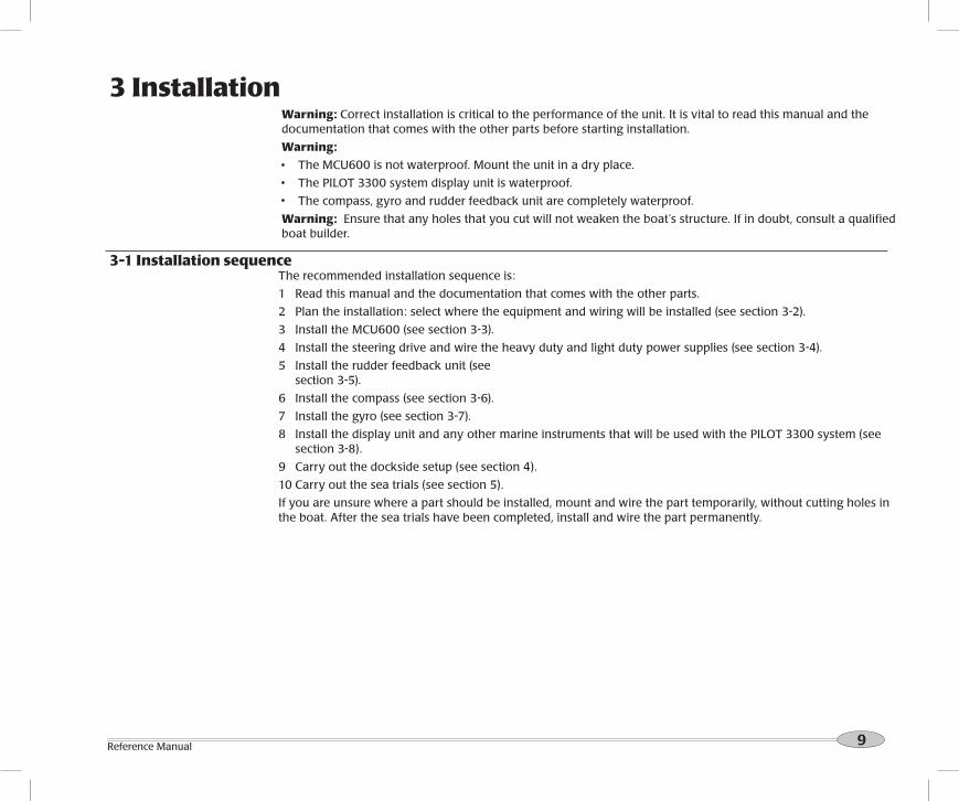
The recommended installation sequence is:
1 Read this manual and the documentation that comes with the other parts.
2 Plan the installation: select where the equipment and wiring will be installed (see section 3-2).
3 Install the MCU600 (see section 3-3).
4 Install the steering drive and wire the heavy duty and light duty power supplies (see section 3-4).
5 Install the rudder feedback unit (see section 3-5).
6 Install the compass (see section 3-6).
7 Install the gyro (see section 3-7).
8 Install the display unit and any other marine instruments that will be used with the PILOT 3300 system (see section 3-8).
9 Carry out the dockside setup (see section 4).
10 Carry out the sea trials (see section 5).
If you are unsure where a part should be installed, mount and wire the part temporarily, without cutting holes in the boat. After the sea trials have been completed, install and wire the part permanently.
3 Installation
3-1 Installation sequence
Warning: Correct installation is critical to the performance of the unit. It is vital to read this manual and the documentation that comes with the other parts before starting installation.
Warning:
The MCU600 is not waterproof. Mount the unit in a dry place.
The PILOT 3300 system display unit is waterproof.
The compass, gyro and rudder feedback unit are completely waterproof.
Warning: Ensure that any holes that you cut will not weaken the boat’s structure. If in doubt, consult a qualified boat builder.

10 Northstar NS3300 Pilot System Intallation
3-2-2 Wiring guideThe PILOT 3300 system has two kinds of cables:
The heavy-duty power supply and steering drive usually require high-current cables:
Select the wire gauge from the wire size table (see section 3-4-2).
Fit high-current cables at least 1 m (3 ft) away from other electronic devices in the boat.
Keep the cables as short as possible.
Twin 2 mm (#14) cable is supplied with the PILOT 3300 system and can be used for the high current cable if its gauge is suitable.
All the other cables are low-current:
Fit low-current cables at least 1 m (3 ft) away from sources of electrical signals or noise, such as the high-current cables, other boat cables, engines, fluorescent lights, power inverters and radio or radar transmitters and antennas.
If the cable for the rudder feedback unit, compass or gyro is too long, do not shorten the cable; instead coil the cable up near the main control unit.
The cable for the rudder feedback unit, compass or gyro can be extended by adding a 10 m (33 ft) extension cable and coupling connector. Do not fit more than one extension cable to each unit.
When fitting any type of cable:
Do not crush, pinch or strain the cable.
Secure the cable at regular intervals.
Ensure no connectors or exposed terminals are in the bilge.
This is a general guide for locating and wiring the parts of the PILOT 3300 system. The instructions for a particular part may have additional requirements.
3-2-1 Location guide Do not mount any part where it can be used as a handhold, where it will interfere with the operation of the
boat or where it might be submerged.
Do not mount any part where it will interfere with launching or retrieving the boat.
Do not mount any part within 0.5 m (20”) of the plane of a radar antenna.
Mount the compass and gyro:
At least 1 m (3 ft) away from sources of electrical signals or noise, such as the batteries, high-current cables, other boat cables, engines, fluorescent lights, power inverters, radio or radar transmitters and antennas.
At least 1 m (3 ft) away from equipment containing a magnet, such as a compass or speaker.
3-2 Installation guide

11Reference Manual
3-3 Installing the MCU600 (Main Control Unit)
IMPORTANT: 200 mm (7.87”) clearance required for cover removal
InstallationFind a suitable location for the unit:
In a dry, cool place; if possible not the engine room.
Close to the high-current power supply and the steering drive, to reduce the length of the high current wiring.
Accessible for installation and service.
If possible on a vertical panel which does not vibrate.
Follow the location guide (see section 3-2-1).
Mount the unit with the cable connectors at the bottom or to one side, using the screws provided. Do not mount the unit with the connectors at the top, because dust or moisture might enter the unit.
200 mm (7.87”)
IMPORTANT: 60 mm (2.36”) clear-ance required for cables
200 mm (7.87”)
140 mm (5.10”)
60 mm (2.36”)
Screws 90 mm (3.54”) apart Screw holes 1
84 mm (7.
24”) apart
55
mm
(2
.16
”)
12
3
1 RFU
2 Gyro
3 Compass / Heading Sensor
Physical

12 Northstar NS3300 Pilot System Intallation
3-4 Installing the power supplies and steering drive3-4-1 Installing the power supplies
The MCU 600 system requires a light duty and a heavy duty power supply, both 12 V DC.Note:
Keep all wiring as short as possible. For the heavy duty supply, use the wire size given in the table (see section
3-4-2). Follow the wiring guide (see section 3-2-2).
Fit strain reliefConnector
cover
Light duty
power
Heavy
duty
Fuse 1 A
12 V DC power
supply, current to
suit drive
Power supply: one switch configurationChoose this configuration to have one switch to turn the PILOT 3300 system and any other instruments on and off.
Circuit breaker or fuse
and switch, current rating
to suit steering drive
Power supply: two switch configurationChoose this configuration to be able to turn the drive power off and leave other instruments powered.
Fit strain reliefConnector
cover
Switch
Heavy duty
power
Fuse 1 ALight duty
power
Note: If powering more than three extra display units or other series instruments, fit another switch and fuse for the light duty power supply for these extra instruments
12 V DC power
supply, current to
suit drive
Circuit breaker or fuse and
switch, current rating to
suit steering drive
MCU600
13Reference Manual
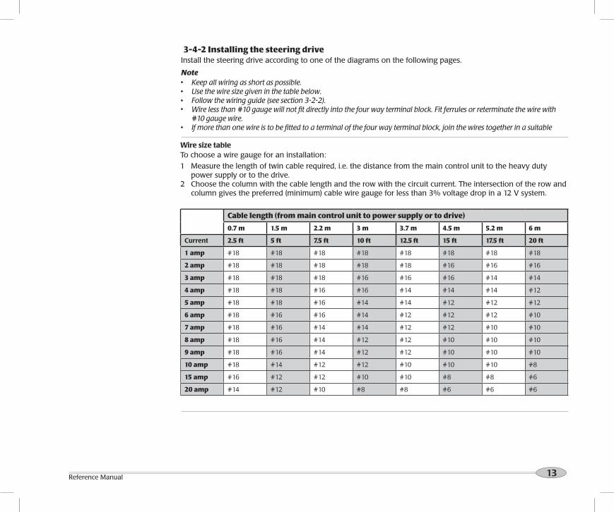
3-4-2 Installing the steering driveInstall the steering drive according to one of the diagrams on the following pages.
Note Keep all wiring as short as possible. Use the wire size given in the table below. Follow the wiring guide (see section 3-2-2). Wire less than #10 gauge will not fit directly into the four way terminal block. Fit ferrules or reterminate the wire with
#10 gauge wire. If more than one wire is to be fitted to a terminal of the four way terminal block, join the wires together in a suitable
Wire size tableTo choose a wire gauge for an installation:
1 Measure the length of twin cable required, i.e. the distance from the main control unit to the heavy duty power supply or to the drive.
2 Choose the column with the cable length and the row with the circuit current. The intersection of the row and column gives the preferred (minimum) cable wire gauge for less than 3% voltage drop in a 12 V system.
Cable length (from main control unit to power supply or to drive)
0.7 m 1.5 m 2.2 m 3 m 3.7 m 4.5 m 5.2 m 6 m
Current 2.5 ft 5 ft 7.5 ft 10 ft 12.5 ft 15 ft 17.5 ft 20 ft
1 amp #18 #18 #18 #18 #18 #18 #18 #18
2 amp #18 #18 #18 #18 #18 #16 #16 #16
3 amp #18 #18 #18 #16 #16 #16 #14 #14
4 amp #18 #18 #16 #16 #14 #14 #14 #12
5 amp #18 #18 #16 #14 #14 #12 #12 #12
6 amp #18 #16 #16 #14 #12 #12 #12 #10
7 amp #18 #16 #14 #14 #12 #12 #10 #10
8 amp #18 #16 #14 #12 #12 #10 #10 #10
9 amp #18 #16 #14 #12 #12 #10 #10 #10
10 amp #18 #14 #12 #12 #10 #10 #10 #8
15 amp #16 #12 #12 #10 #10 #8 #8 #6
20 amp #14 #12 #10 #8 #8 #6 #6 #6
14 Northstar NS3300 Pilot System Intallation
Fit strain relief
Wiring polarity
does not matter.
Motor
MCU600
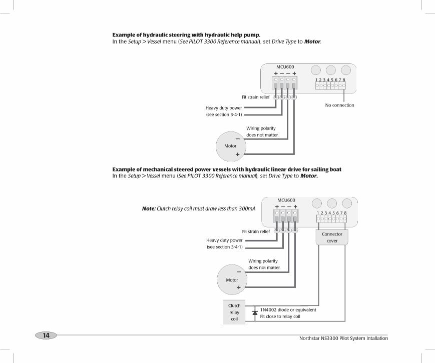
Example of hydraulic steering with hydraulic help pump.In the Setup > Vessel menu (See PILOT 3300 Reference manual), set Drive Type to Motor.
Example of mechanical steered power vessels with hydraulic linear drive for sailing boatIn the Setup > Vessel menu (See PILOT 3300 Reference manual), set Drive Type to Motor.
Motor
Clutch
relay
coil
1N4002 diode or equivalent
Fit close to relay coil
Connector
cover
No connection
MCU600
Heavy duty power
(see section 3-4-1)
Fit strain relief
Wiring polarity
does not matter.
Heavy duty power
(see section 3-4-1)
Note: Clutch relay coil must draw less than 300mA

15Reference Manual
Installing a electric drive motor with clutch relayIn the Setup > Vessel menu (See PILOT 3300 system Reference manual), set Drive Type to Motor.
Installing a continuous running pump and solenoid valves.In the Setup > Vessel menu (See PILOT 3300 system Reference manual), set Drive Type to Spool ground.
Fit strain relief
Wiring polarity
does not matter.
Motor
MCU600
Clutch
coil
1N4002 diode or equivalent.
Fit close to relay coil
1N4002 diode or equivalent
Fit close to relay coil
Relay coil
MCU600
1N4002 diode or equivalent
Fit close to relay coil
Relay contacts
Relay coil
Starboard
Port
Motor
Fit strain relief
Heavy duty power (see section 3-4-1)
Heavy duty power (see section 3-4-1)
Wiring polarity
does not matter.
Note: Motor is not required for engine PTO systems.
Relay contacts
Note: Relay is required if the clutch circuit is greater than 300 mA.
Note: Relay is required if the clutch circuit is greater than 300 mA.
Connector
cover
Connector
cover

16 Northstar NS3300 Pilot System Intallation
Installing solenoid valves or relays with jog or electric steeringIn the Setup > Vessel menu (See PILOT 3300 Reference manual), set Drive Type to Spool ground.
MCU600
Starboard
Port
Fit strain relief
No connection
Jog/steer controls
Heavy duty power
(see section 3-4-1)

17Reference Manual
3-5 Installing the RFU (rudder feedback unit)
Physical
10 m (33 ft) cable
Arm
90 mm
(3.5”)
220 mm
(8.7”)
Base
Linkage to
rudder
Rudder
shaft
Arm rotates freely around base.
LT8 connector
These two
distances to
be equal.
Connecting rod, with
quick release fittings and
lock nuts each end
End of connecting rod snaps into one of the
holes on the arm.
Mounting requirementsThese two
distances to
be equal.
Base to be adjacent
to rudder shaft so that
this angle is 90°
Rudder shaft to be par-
allel to shaft in base.
Rudder linkage and
arm to move in the
same plane
Note The unit is completely waterproof but should not be immersed. Mount the unit on a panel which does not vibrate. Follow the location guide (see section 3-2-1).
Adjust position of rod on
arm if required.
Cut connecting
rod if required. Thread = M5
18 Northstar NS3300 Pilot System Intallation
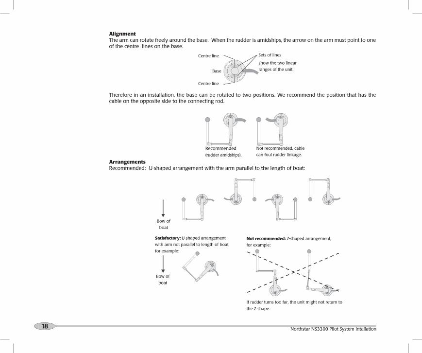
AlignmentThe arm can rotate freely around the base. When the rudder is amidships, the arrow on the arm must point to one of the centre lines on the base.
Centre line
Therefore in an installation, the base can be rotated to two positions. We recommend the position that has the cable on the opposite side to the connecting rod.
Centre line
Sets of lines
show the two linear
ranges of the unit.Base
Recommended(rudder amidships).
ArrangementsRecommended: U-shaped arrangement with the arm parallel to the length of boat:
Satisfactory: U-shaped arrangement
with arm not parallel to length of boat,
for example:
Not recommended: Z-shaped arrangement,
for example:
If rudder turns too far, the unit might not return to
the Z shape.
Bow of
boat
Bow of
boat
Not recommended, cable
can foul rudder linkage.
19Reference Manual
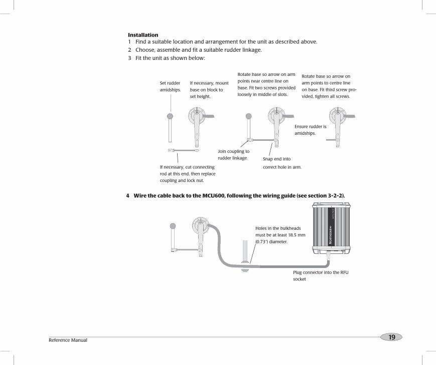
Installation1 Find a suitable location and arrangement for the unit as described above.
2 Choose, assemble and fit a suitable rudder linkage.
3 Fit the unit as shown below:
If necessary, mount
base on block to
set height.
Set rudder
amidships.
Rotate base so arrow on arm
points near centre line on
base. Fit two screws provided
loosely in middle of slots.
Rotate base so arrow on
arm points to centre line
on base. Fit third screw pro-
vided, tighten all screws.
Join coupling to
rudder linkage. Snap end into
correct hole in arm.
Ensure rudder is
amidships.
If necessary, cut connecting
rod at this end, then replace
coupling and lock nut.
4 Wire the cable back to the MCU600, following the wiring guide (see section 3-2-2).
MCU600
Plug connector into the RFU
socket
Holes in the bulkheads
must be at least 18.5 mm
(0.73”) diameter.

20 Northstar NS3300 Pilot System Intallation
3-6 Installing the Compass
Physical101 mm, (4”)
Mounting holes
for screws
97 mm,
(3.8”)
71 mm, (2.8”)
10 m (32.8 ft) LT8 connector
LocationMount the compass:
At least 1 m (3 ft) away from any steel or iron boat part, such as: a steel hull, deck, cabin or steel reinforcing in ferro-cement hulls steel equipment such as motors and cooking equipment places where steel objects are stored, such as the anchor locker and storage lockers
At least 2 m (6 ft) away from equipment with a magnet and equipment which generates electromagnetic fields, such as a compass, a battery, high current wiring, an electric motor and a radio or radar transmitter or antenna.
As close as possible to the centre of movement of the boat, to minimise how much the compass moves when the boat rocks and pitches. If the compass can not be mounted at the centre of movement, it is usually best to mount the compass as low as possible.
On a vertical panel which does not vibrate.The unit is completely waterproof but should not be immersed. The compass is not affected by other metals, such as stainless steel, copper or brass. Follow the location guide (see section 3-2-1). Fibreglass or wood hull and cabin: mount compass at the centre of movement (for planing hulls, the centre of movement is usually close to the stern):
Steel hull, non-steel cabin: mount compass 1 m,
(3 ft) above hull:Steel hull and steel cabin: mount compass on a pole 1 m (3 ft)
above the hull and at least 1 m (3 ft) from the cabin:
At least 1 m (3 ft)1 m (3 ft)
1 m (3 ft)

21Reference Manual
Installation
1 Find a suitable location for the unit as described above.
2 Mount the unit with the three screws provided. Use a level to ensure the unit is vertical to within 10°.
Less than
10° 10°
3 Wire the cable back to the MCU600, following the wiring guide (see section 3-2-2).
Less than 10° 10°
MCU600
Plug connector into the Compass/HS socket
Holes in the bulkheads
must be at least 18.5 mm
(0.73 in) diameter.
Note If you move the compass with respect to the gyro while the power is on, wait for the
heading to stabilize.

22 Northstar NS3300 Pilot System Intallation
3-7 Installing the GyroPhysical
Mounting holes
for screws
LT8 connector
LocationMount the gyro as close as possible to the centre of movement of the boat, to minimize how much the gyro moves when the boat rocks and pitches.
Mount the gyro on a panel which does not vibrate.
The unit is completely waterproof but should not be immersed. Follow the location guide (see section 3-2-1).
The Ideal location is at the centre of movement (for planing hulls, the centre of movement is usually close to the stern).
101 mm, (4”)
97 mm,
(3.8”)
71 mm, (2.8”)
10 m (32.8 ft)

23Reference Manual
Installation1 Find a suitable location for the unit as described above.2 Mount the unit with the three screws provided. Use a level to ensure the unit
is vertical to within 10°.
Less than
10° 10°
3 Wire the cable back to the MCU600, following the wiring guide (see section 3-2-2).
Less than
10° 10°
MCU600
Plug connector into the Gyro socket
Holes in the bulkheads
must be at least 18.5 mm
(0.73”) diameter.
Note If you move the gyro with respect to the compass while the power is on, wait for the heading to stabilise.

24 Northstar NS3300 Pilot System Intallation
There are two mounting arrangements:
• Flush mounting requires a solid panel with access behind for wiring and mounting screws. After flush mounting, the display cannot be tilted or moved after installation to reduce any unwanted glare or reflections. Carefully select the best viewing position before installation. This would generally be in a shaded area.
Flush mounting directions
1 Cut a hole in the bulkhead for the display unit using the flush mount template as a guide.
2 Drill four holes for the mounting studs using the flush mount template as a guide.
3 Screw the four studs into the brass inserts in the back of the display unit.
4 Sit the display unit in place and fit the washers and nuts to the studs.
• Bracket mounting requires a panel for mounting the bracket. Ensure that the panel is not likely to deform and is not subject to excessive vibration. The bracket can be tilted and the dispaly can be removed after each use.
Select a position where the display unit will be:
• At least 4" (100 mm) away from the compass.
• At least 12" (300 mm) away from any radio transmitter.
• At least 4 ft (1.2 m) away from any antenna.
• Easy to read and operate. If possible, mount the display unit in front of the navigator or to the right of the navigator because the LCD display is more readable from these positions.
• Not exposed to the direct sun or water.
• Protected from physical damage during
rough sea passages.
• Easy to access the DC power source.
• Convenient to route the transducer cables.
Bracket mounting directions
1 Fix the mounting bracket onto the boat using the four stainless steel screws.
2 Hold the display unit in place in the mounting bracket. Fit the mounting bracket knobs into the display unit and do up the knobs loosely.
3 Adjust the tilt of the display for best viewing, then hand tighten the knobs on the mounting bracket.
3-8 Installing the PILOT 3300 display unit and other instruments

25Reference Manual
Wiring the display unit
MCU600
Display
unit
Display unit cable, Requires 18 mm (0.7”) hole
through bulkhead.
Co
nn
ecto
r co
ver
Clutch relay out: 8NMEA2 - in/out: 7
NMEA1 - in: 6NMEA common: 5
NavBus -, Blue: 4NavBus +, Orange: 3
Ground, Black: 212 V power +, Red: 1
Optional external beepers and lamps for
the external alarm. If the beepers and
lights require more than 250 mA, fit an
external relay.
8-way connector
Green
Light duty power
(see section 3-4-1)
NoteWire the display unit power wires (red and black wires) to the eight way connector terminals 1 and 2 to ensure the display unit and main control unit have the same light duty power supply.
Follow the wiring guide (see section 3-2-2).
•
•
Plug power cable into the
Black socket on the rear of the
PILOT 3300 display.
Yellow (ignition wire)White (isolate, do not use)Brown (isolate, do not use)
26 Northstar NS3300 Pilot System Intallation
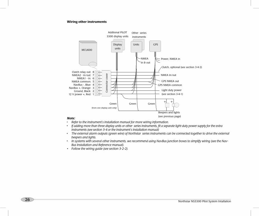
Wiring other instruments
MCU600
Display
units
Addtional PILOT
3300 display units Other series
instruments
Units
NMEA in/out
NMEA
in & out
GPS NMEA out
GPS NMEA common
Power, NMEA in
Beepers and lights
(see previous page)
Co
nn
ecto
r co
ver
Note: Refer to the instrument’s installation manual for more wiring information. If adding more than three display units or other series instruments, fit a separate light-duty power supply for the extra
instruments (see section 3-4 or the instrument’s installation manual) The external alarm outputs (green wire) of Northstar series instruments can be connected together to drive the external
beepers and lights. In systems with several other instruments, we recommend using NavBus junction boxes to simplify wiring (see the Nav-
Bus Installation and Reference manual).• Follow the wiring guide (see section 3-2-2).
Clutch relay out: 8NMEA2 - in/out: 7
NMEA1 - in: 6NMEA common: 5
NavBus -, Blue: 4NavBus +, Orange: 3
Ground, Black: 212 V power +, Red: 1
Light duty power
(see section 3-4-1)
Clutch, optional (see section 3-4-2)
GPS
GreenGreenGreen
(from one display unit only)

27Reference Manual
4 Dockside setup
1 Turn the PILOT 3300 system on (See PILOT 3300 Reference manual). If the rudder moves, immediately turn the power off.
If you try to enter AUTO and the rudder feedback unit or compass have not yet been calibrated, then the PILOT 3300 system will displays an error.
2 If the PILOT 3300 system has been used before, reset all user data to the factory defaults. Go to Factory reset > Both in the Setup System menu (See PILOT 3300 Reference manual).
3 Enter the user data listed in the User Data table below (See PILOT 3300 Reference manual to find what each data item means and how to enter the data). Beside each item, write the value of the user data that you enter.
Perform the dockside setup: after installing a PILOT 3300 system (see section 3)
after a part has been changed or if a problem is suspected
After dockside setup, perform the sea trials (see section 5 ).
4-1 Start dockside setup
Warning: Until the rudder feedback unit is calibrated (see section 4-2), there is no rudder limit. The user must ensure that rudder is not driven onto an endstop when using the jog command (see PILOT 3300 Reference manual).
4-2 Calibrating the rudder feedback unit
To calibrate the rudder feedback unit go to Rudder in the Setup > Calibrate menu. Follow the on-screen instructions presented by the calibration wizard (See PILOT 3300 Reference manual).
This procedure matches the rudder feedback unit to the rudder.
Note
To exit the calibration at any time, press ESC.
If you do not move the rudder as prompted or the rudder feedback unit is not working then the PILOT 3300 system can not finish the calibration. The PILOT 3300 system will display an error. Press ESC, fix the problem and repeat the calibration.
In normal operation, the PILOT 3300 system will not turn the rudder closer than 3° to an endstop.

28 Northstar NS3300 Pilot System Intallation
NoteTo calibrate the Compass unit go to Compass in the Setup > Calibrate menu. Follow the on-screen instructions presented by the calibration wizard (See PILOT 3300 Reference manual).
To exit the calibration at any time, press ESC. If the boat is not turned as prompted or the compass is not working then calibration can not be completed, the PILOT
3300 system displays an error. Press ESC, fix the problem and repeat the calibration. Local disturbances in magnetic field may affect the compass. Calibration must be preformed away from large metal
structures such as marinas, large ships etc.; this is the responsibility of the user. Ensure that both sources are referencing the same north (true or magnetic). If your magnetic compass has not been
calibrated then you can use another source for heading. If using vessel’s compass then ensure that the deviation tables are applied to check the autopilot’s compass.
5-1 Calibrating the compass
5 Sea trialsPerform the sea trials:
After performing the dockside setup (see section 4). To check the operation of the PILOT 3300 system.For the sea trials, sail in an open area where there are no other craft or obstructions. The sea should be calm, the wind speed as low as possible and there should be no currents.
5-2-1 Aligning the compass (Align heading)This aligns the PILOT 3300 system compass to display the correct heading.
The compass can be aligned either to a reference compass or to a GPS connected to the PILOT 3300 system. Ensure there is no cross-wind or current.
To align the Compass unit go to Align heading in the Setup > Calibrate menu. Follow the on-screen instructions presented by the calibration wizard (See PILOT 3300 Reference manual).
5-2-2 Aligning the Rudder (Centre rudder)This sets the rudder setting to sail a straight course. Ensure there is no cross wind or current.
To align the rudder go to Centre rudder in the Setup > Calibrate menu. Follow the on-screen instructions presented by the calibration wizard (See PILOT 3300 Reference manual).
5-2 Aligning the compass and the rudderThe compass or rudder can be aligned separately.

29Reference Manual
Appendix A - Specifications - MCU600
Electrical: Drive power supply: 10.5 to 16.5 V DC, 20 A maximum
8-Way Terminal power supply: 10.5 to 16.5 V DC, 300 mA.
Other optional instruments: refer to the instrument’s Reference manual.
Interfaces: NavBus: connection to other Northstar instruments and PILOT 3300 display unit.
NMEA 0183 ports: NMEA 1: Input; NMEA 2: Can be programmed to be an input or output
NMEA 0183 output messages: HDG, HDT, RSA;
NMEA 0183 input messages: APA, APB, BOD, BWC, MWD, MWV, RMA, RMB, RMC, VHW, VTG, XTE
Standards compliance:
EMC compliance
USA (FCC): Part 15 Class B.
Europe (CE): EN301 843-1 New Zealand and Australia (C Tick): AS-NZS 3548.
Environment:
Compass: IPx6 and IPx7 - completely waterproof. Gyro: IPx6 and IPx7 - completely waterproof. Rudder feedback unit: IPx6 and IPx7 - completely waterproof. MCU600 Main unit: Not waterproof - requires a cool, dry, clean environment.
MCU600 Main unit 8-way Terminal connections:
Signal
1 Light duty power positive, 10.5 to 16.5 V DC
2 Light duty power supply common
3 NavBus +
4 NavBus —
5 NMEA common
6 NMEA in 1
7 NMEA in 2
8 Steering clutch relay drive output, switched ground to turn relay on, 30 V DC, 300 mA maximum
MCU600 Main unit Drive connections:
Signal
1 Heavy duty power positive, 10.5 to 16.5 V DC
2 Heavy duty power negative
3 Steering drive negative output
4 Steering drive positive output
MCU600 Internal Fuse:
2x fuses - both fuses are the same
Type: ATC - Automotive blade
Rating: 20A
30 Northstar NS3300 Pilot System Intallation
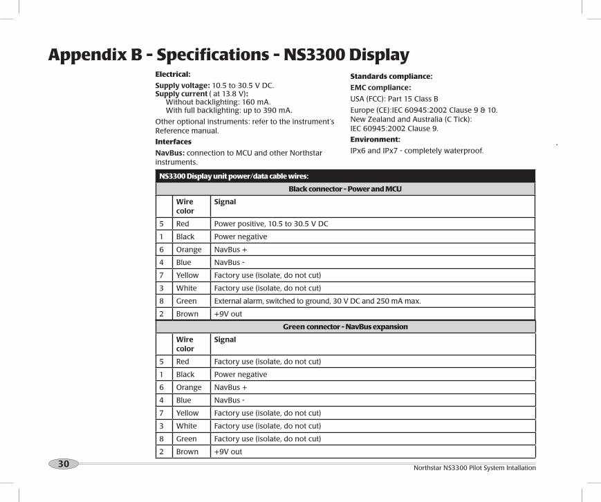
Electrical:
Supply voltage: 10.5 to 30.5 V DC. Supply current ( at 13.8 V): Without backlighting: 160 mA. With full backlighting: up to 390 mA.
Other optional instruments: refer to the instrument’s Reference manual.
Interfaces
NavBus: connection to MCU and other Northstar instruments.
NS3300 Display unit power/data cable wires:
Black connector - Power and MCU
Wire color
Signal
5 Red Power positive, 10.5 to 30.5 V DC
1 Black Power negative
6 Orange NavBus +
4 Blue NavBus -
7 Yellow Factory use (isolate, do not cut)
3 White Factory use (isolate, do not cut)
8 Green External alarm, switched to ground, 30 V DC and 250 mA max.
2 Brown +9V out
Green connector - NavBus expansion
Wire color
Signal
5 Red Factory use (isolate, do not cut)
1 Black Power negative
6 Orange NavBus +
4 Blue NavBus -
7 Yellow Factory use (isolate, do not cut)
3 White Factory use (isolate, do not cut)
8 Green Factory use (isolate, do not cut)
2 Brown +9V out
Standards compliance:
EMC compliance:
USA (FCC): Part 15 Class B
Europe (CE):IEC 60945:2002 Clause 9 & 10. New Zealand and Australia (C Tick): IEC 60945:2002 Clause 9.
Environment:
IPx6 and IPx7 - completely waterproof.
Appendix B - Specifications - NS3300 Display
31Reference Manual
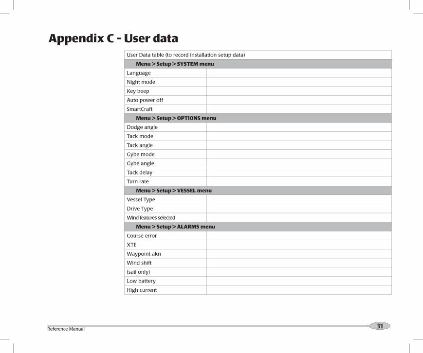
Appendix C - User dataUser Data table (to record installation setup data)
Menu > Setup > SYSTEM menu
Language
Night mode
Key beep
Auto power off
SmartCraft
Menu > Setup > OPTIONS menu
Dodge angle
Tack mode
Tack angle
Gybe mode
Gybe angle
Tack delay
Turn rate
Menu > Setup > VESSEL menu
Vessel Type
Drive Type
Wind features selected
Menu > Setup > ALARMS menu
Course error
XTE
Waypoint akn
Wind shift
(sail only)
Low battery
High current

32 Northstar NS3300 Pilot System Intallation
Menu > Setup > UNITS menu
Distance
Compass
Magnetic variation
Wind
Menu > Setup > COMMS menu
NMEA mode
NavBus group
Menu > Setup > PROFILES menu
Profile (user1)
Parameters:
Adaptive
Response
Ratio
Advanced:
Trim
C-rudder
GPS gain
Wind gain
Profile (user2)
Parameters:
Adaptive
Response
Ratio
Advanced:
Trim
C-rudder
GPS gain
Wind gain
Profile (user3)
Parameters:

33Reference Manual
Adaptive
Response
Ratio
Advanced:
Trim
C-rudder
GPS gain
Wind gain
Profile (user 4)
Parameters:
Adaptive
Response
Ratio
Advanced:
Trim
C-rudder
GPS gain
Wind gain
Profile (user5)
Parameters:
Adaptive
Response
Ratio
Advanced:
Trim
C-rudder
GPS gain
Wind gain

34 Northstar NS3300 Pilot System Intallation
Notes
MMoore
Text Box
Note: This document has not been formally checked, it is for reference only.