nr. 4 - Vulcana Gas · 1 Digital chronothermostat ... 1 Operator's instruction booklet 1...
19
The convector is supplied in two cardboard packages: - Convector - Fume exhaust and combustion air inlet pipes. Contents of convector package: 1 Convector 1 Digital chronothermostat 2 Tie-rods (positioned inside the casing) 1 Metal template 1 Document envelope: 1 Operator's instruction booklet 1 Installer's instruction booklet 1 Gas transformation kit 1 Spare parts catalogue 1 Warranty certificate 1 Warranty label 1 Power socket 4 Ø 8 mm anchors for fastening template Fume exhaust and combustion air inlet pipes: To install the CONVECTOR, the PIPE KIT is required that is most suitable to the type of combustion air inlet and fume exhaust system to be created. This must be ordered separately from the appliance and selected from among the following: CONTENTS OF PIPE KIT Ø 32 COMBINED END PIECE P ACKAGE (code TP320S 00000): 1 Tap with union 2 Ø 32 pipes L=500 mm 1 Combined pipe end piece Ø 32 mm 4 Ø 6 mm wall anchors for fastening end piece 2 Guide arms 6 Ø 9 mm anchors for fastening the guide arms 8 Self-threading screws for fastening the tie-rods 11 INSTALLER 500 nr. 8 3,9 x 6,5 nr. 6 Ø 9 nr. 4 (Ø 6mm) Ø64 RECEIPT OF PRODUCT
Transcript of nr. 4 - Vulcana Gas · 1 Digital chronothermostat ... 1 Operator's instruction booklet 1...

The convector is supplied in two cardboard packages:- Convector- Fume exhaust and combustion air inlet pipes.
Contents of convector package:1 Convector1 Digital chronothermostat2 Tie-rods (positioned inside the casing)1 Metal template1 Document envelope:1 Operator's instruction booklet1 Installer's instruction booklet1 Gas transformation kit1 Spare parts catalogue1 Warranty certificate1 Warranty label1 Power socket4 Ø 8 mm anchors for fastening templateFume exhaust and combustion air inlet pipes:To install the CONVECTOR, the PIPE KIT is required that is most suitable to the type of combustion airinlet and fume exhaust system to be created. This must be ordered separately from the applianceand selected from among the following:
CONTENTS OF PIPE KIT Ø 32 COMBINED END PIECE PACKAGE (code TP320S 00000):
1 Tap with union2 Ø 32 pipes L=500 mm1 Combined pipe end piece Ø 32 mm4 Ø 6 mm wall anchors for fastening end piece2 Guide arms6 Ø 9 mm anchors for fastening the guide arms8 Self-threading screws for fastening the tie-rods
11INSTALLER
500
nr. 83,9 x 6,5
nr. 6Ø 9
nr. 4(Ø 6mm)
Ø64
RECEIPT OF PRODUCT

CONTENTS OF PIPE KIT Ø 54 COMBINED END PIECE PACKAGE (CODE TP540S 00000):
1 Tap with union1 Ø 54 pipes L=500 mm1 Combined pipe end piece Ø 54 mm4 Ø 6 mm wall anchors for fastening end piece2 Guide arms6 Ø 9 mm anchors for fastening the guide arms8 Self-threading screws for fastening the tie-rods2 Diaphragms (Mod. 40 - 60 only)4 O-Rings for pipes
CONTENTS OF PIPE KIT Ø32 SEPARATE END PIECES PACKAGE (CODE TP32SS 00000)
1 Tap with union3 Curves Ø 32 mm3 Pipes Ø 32 L=500 mm2 Pipes Ø 32 L=1000 mm2 Pipe end pieces Ø 32 mm4 Self-threading screws for fastening end pieces2 Flanges in stainless steel8 Ø 6 mm anchors for fastening flanges2 Guide arms6 Ø 9 mm anchors for fastening guide arms8 Tie-rod retention screws
12 INSTALLER
nr. 4O-Ring
500
nr. 83,9 x 6,5
nr. 6Ø 9
nr. 4(Ø 6mm)
Ø64
1000
mm
500 mm
500 mm
nr. 8
(Ø 6
mm
)
nr. 6Ø 9
nr. 123,9 x 6,5
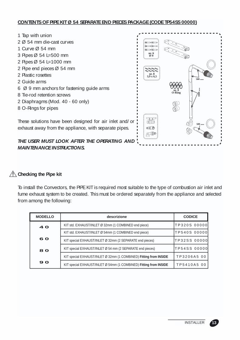
CONTENTS OF PIPE KIT Ø 54 SEPARATE END PIECES PACKAGE (CODE TP54SS 00000)
1 Tap with union2 Ø 54 mm die-cast curves1 Curve Ø 54 mm3 Pipes Ø 54 L=500 mm2 Pipes Ø 54 L=1000 mm2 Pipe end pieces Ø 54 mm2 Plastic rosettes2 Guide arms6 Ø 9 mm anchors for fastening guide arms8 Tie-rod retention screws2 Diaphragms (Mod. 40 - 60 only)8 O-Rings for pipes
These solutions have been designed for air inlet and/orexhaust away from the appliance, with separate pipes.
THE USER MUST LOOK AFTER THE OPERATING ANDMAINTENANCE INSTRUCTIONS.
Checking the Pipe kit
To install the Convectors, the PIPE KIT is required most suitable to the type of combustion air inlet andfume exhaust system to be created. This must be ordered separately from the appliance and selectedfrom among the following:
1000
mm
500 mm
500 mm
nr. 8O-Ring
nr. 83,9 x 6,5
nr. 6Ø 9
13INSTALLER
4 0
6 0
8 0
9 0
MODELLO CODICE
KIT std. EXHAUST/INLET Ø 32mm (1 COMBINED end piece)
descrizione
KIT std. EXHAUST/INLET Ø 54mm (1 COMBINED end piece)
KIT special EXHAUST/INLET Ø 32mm (2 SEPARATE end pieces)
KIT special EXHAUST/INLET Ø 54 mm (2 SEPARATE end pieces)
KIT special EXHAUST/INLET Ø 32mm (1 COMBINED) Fitting from INSIDE
KIT special EXHAUST/INLET Ø 54mm (1 COMBINED) Fitting from INSIDE
T P 3 2 0 S 0 0 0 0 0
T P 5 4 0 S 0 0 0 0 0
T P 3 2 S S 0 0 0 0 0
T P 5 4 S S 0 0 0 0 0
T P 3 2 0 6 A 5 0 0
T P 5 4 1 0 A 5 0 0
This is a sealed and environment-friendlyappliance. Combustion air is extracted only fromoutside- DO NOT use accessories or components forposit ioning that are not approved by theManufacturer as this could cause a serioushazard.- DO NOT place the power cable on hot surfacessuch as the air diffusion grilles or fume extractionpipesAfter installation, the fitter must inform the userwhat to do when the appliance is running:DO NOT place curtains, towels and similar on theappliance as this could cause malfunctions andprevent proper room ventilation.
- DO NOT obstruct the appliance inlet/outlet with hung-up washing or carpets.
14 INSTALLER
INSTALLATION AREA
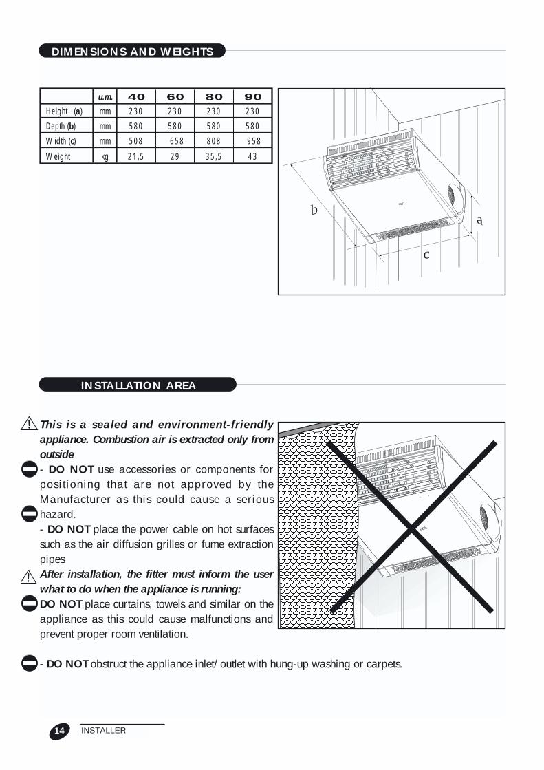
DIMENSIONS AND WEIGHTS
ab
c
230 230 230mmHeight (a)
580 580 580mmDepth (b)
508 658 958mmWidth (c)
40 60 90u.m.
21,5 29 43kgWeight
230
580
808
80
35,5

Before completing any masonry works, make surethere is enough room for the appliance to operateand for it to be serviced. To proceed correctly, it isimportant to make sure the wall or ceiling to whichthe appliance is to be secured is suitable for sup-porting the weight of the appliance; in this respect,check the anchors provided to make sure they areable to sustain the appliance taking into accountthe material of which the wall or ceiling is made. Ifthey are not, replace them with other more suitableones. Make sure there is no matchboarding or pla-stic inserts which are not heat resistant and whichcould come into contact with the fume extractionpipes.
In case of a wall made of material with low resistanceto heat, an interspace can be made around the fumeexhaust pipe that is insulated with material resistant tohigh temperatures or else a hole can be made with adiameter that is at least 4 cm bigger than that of thefume exhaust pipe.
Installing the appliance in bathrooms/showers or nearwater dispensing units is forbidden. In such cases spe-cial protections must be made that ensure the applianceconforms with "specific" Electrical Safety Standards.
Note*: to prevent directing the air flow to people height, the appliance should be fitted at a MINheight of 2.30 m and a MAX height of 3.00 m to prevent any air stratification.
15INSTALLER
INSTALLATION AND MASONRY WORKS
Min 50
Min 150
Min 500
Min 150
Ø 65Ø 110
129 mm
Min 150
210,5
45
240
240
75

TYPES OF INSTALLATION ACCORDING TO UNI CIG 7129
The types of pipe installation are shown below (inlet and exhaust) according to the indications of theapplicable UNI CIG 7129 standard, for product having the following construction and installationcharacteristics.
16 INSTALLER
C 13 C 33
C 53 C 63
TYPES OF INSTALLATION ACCORDING TO UNI CIG 7129
MENSOLA
WITH AIR INLET AND FUMEEXHAUST FAR AWAY FROM EACHOTHER.
WITH NEARBY AIR INLET ANDFUME OUTLET ON THE SAME WALL.
WITH NEARBY VERTICALAIR INLET AND FUMEEXHAUST, POSITIONED ON ROOF.
WITH AIR INLET AND FUMEEXHAUST FAR FROM EACHOTHER.INLET THROUGH STACK AND EXHAUSTPIPES PASSING THROUGH SAME STACK.

CEILING INSTALLATION WITH PARALLEL PIPES AND COMBINED END PIECE
Installation "against the wall" (crossed by inlet and exhaust pipes)
Before installing, make sure the diameters, the total lengths and the end pieces of the pipes and theiroverall flow resistances do not exceed the prescribed limits as indicated in the chapter on Pipelengths and Pressure loss.
Fitting the guide arms and template:Choose where to position the convector on the ceiling,fit the 2 guide arms, according to the following proce-dure:- using the 4 screws provided, fasten the 2 tie-rods (3),aligning the 2 guide arms (2);- mark the 6 holes for fastening the 2 guide arms (2).Drill the holes using a Ø 9 mm bit if the providedanchors are used. This diameter will be different ifother anchors, considered more suitable, are used.Always remember that the working width of the slot isØ 9 mm;- fasten the guide arms + tie rod structure (2+3) to theceiling so the two arms fasten onto the wall (important:the 2 tie-rods must be fitted in both the ceiling solutionand the bracket solution);- Move the metal template (5) close to the arm (2) (theright one), marking the centre of the inlet and exhaustpipe outlet holes and the template fastening holes.Alongside hole B, make the centring hole using an Ø 8mm bit, fasten the template (5), using 2 Ø 8 mmanchors positioned at holes B and D. Once centring has been made, disconnect the half-cut discfrom the hole on the template (5).Make a hole using a suitable milling unit or by making a series of small holes in the circumference.
IMPORTANT! Detach only the central Ø 65 mm disc for pipes diameter Ø 32 mm and ring Ø 110mm for pipes diameter Ø 54 mm.
Proceed to drill the wall taking into account the details shown on the Table.
17INSTALLER
B
5 D
2
3
Ø 32Ø 54
u.m. 40 60 90TUBAZIONI
mmØ wall hole for parallel pipes 65/110 65/110 110
mmØ air inlet/exhaust pipes 32/54 32/54 54
mLength of parallel pipes for COMBINED end piece 5/15 1/15 10
mOverall length of pipes 0,08
80
110
54
15

Installation "away" from the wall (crossed by air inlet and fume exhaust pipes)Installation is practically the same as that "against the wall". The only difference is that the template(5) has to be positioned without the reference of the guide arm (2). It is best therefore to install theguide arms, position the convector and then fit the template on the wall.Fit the pipes according to lengths and layout and join these to the union on the convector and tem-plate.
Adapting the outlet union to the pipe diameterQuesta operazione si rende necessaria solosui Termoconvettori 40 - 60, qualora si passi,dove è consentito, dalle tubazioni Ø 32 mm aquelle Ø 54 mm e viceversa.The appliance is always supplied by theManufacturer ready to use the Ø 32 mmpipes.This operation must be performed before fit-ting the convector on the guide arms.Proceed as follows:- loosen the screws (2) of the outlet union (1);- remove the inlet/exhaust pipes;- fit the diaphragms (3)(for Ø 32 mm);- fit the pipes back on (be careful to correctlyfit the two "round-offs").- fit the outlet union back on (1).Assembly must be made as shown in the illu-stration.
Fitting parallel "air inlet/fume exhaust" pipesThis solution has been conceived to make air inlet/exhaust directly behind the appliance or awayfrom the appliance using parallel pipes; formax diameters and lengths, see the aboveTable.Adapt the length of the pipes provided tothe actual thickness of the wall Thick. + Xmm, cutting off any excess part.Complete the missing section with the pipesnecessary for "away" installation, remem-bering to fasten and insulate these whennecessary.
18 INSTALLER
L = Sp + x
Spx
Ø 65Ø 110
Min 150
Ø 32
Ø 54
13
2

The pipes must always be cut perpendicular to the axis of the pipe itself, being very careful not todeform the pipes; after cutting, carefully remove any remaining burrs.
On the pipes featuring seals, the O-rings must not protrude from their seats. For easier fitting, usesilicone or soapy grease.Select the type of combined end-piece fitting: if fitted from inside together with the pipes (1a, 1b,small flange) or that fitted from the outside (2a, 2b, large flange).
Fitting pipes with combined end piece fastened from insideFit the combined end piece (2) on the pipes after cutting them in the required lengths and fasteningthem using the screws provided (1). Make sure the fume exhaust hole of the end piece (a) is positio-ned high up.
If not already done, detach the half-cut disc from the hole on the template and then fit the pipeassembly in the wall, positioning it so the small flange of the combined end piece is flush with theouter wall. Secure the pipes with mortar so they cannot turn, being careful not to dirty them inside.To cover the drilling imperfections on the wall, if the outer end piece is easy to reach, we suggestusing a plastic rosette (3) (4) which can be fastened with silicone or other adhesives for plastic mate-rials.
19INSTALLER
1a 1b
Ø 54 mmØ 32 mm
2b2a
Ø 65Ø 110 Ø 110
Ø 160
a
Ø 65Ø 110
1 2 3
4

Fitting parallel pipes with combined end piece faste-ned from outsideFit the pipe assembly without end piece in the wall,positioning it so the pipes are flush with the outer walland perfectly vertical.Fit the outer end piece on the pipes, making sure thefume exhaust hole (a, fig. on previous page) of the endpiece is positioned high up; now proceed to fasten thecombined end piece (1) using the four Ø 6 mmanchors provided (2).Make sure the end-piece pipes fit on correctly toensure the seal of the O-rings on the pipes featuringseals.
"BRACKET" INSTALLATION WITH PARALLEL PIPES AND COMBINED END PIECEBefore making any installation, carefully read the Table on page 18 to make sure the diameters, thetotal lengths and the end pieces of the pipes and their overall flow resistances do not exceed thoseprescribed!When the convector cannot be fitted directly on the ceiling, two brackets are available to be assem-bled together with the guide arms + arm tie-rods, to make a supporting bracket.For correct “bracket” installation, proceed as follows:- check the consistency of the installation wall and position the metal template (5);- rest bracket (4) at the required height against the wall and level with a spirit level;- mark the three retention holes for bracket (4);- drill with a Ø 9 mm drill if the provided anchors are used; use a different diameter if otheranchors, thought to be more appropriate, are used, remembering that the working width of the slotis Ø 9 mm;- fasten the bracket (4) to thewall;- assemble the guide arm (2);Move the metal template (5)close to the bracket (4),marking the centre of theoutlet hole of the inlet andexhaust pipes and those forfastening the template.
20 INSTALLER
Ø 65Ø 110
2
Min 150
1
a
1
B3
2
5
4

- At hole B, make the centre hole using a Ø 8 mm drilland then fasten the template using the 2 Ø 8 mmanchors provided.After centring, detach the half-cut disc from the hole onthe template.
Detach only the central Ø 65 mm disc for pipes dia-meter Ø 32 mm and ring Ø 110 mm for pipes dia-meter Ø 54 mm.- Drill the hole taking into account the details shown onthe Table on page 18, using a suitable cutter or a suc-cession of small holes made in the circumference.- assemble the arm tie-rods (3, fig. on previous page)with the guide arms (2).- assemble the right bracket with the right guide arm.- position the two guide arms + tie-rods against thewall, assembling the left bracket with its guide arm.- mark the three retention holes for the second bracketwith the aid of a spirit level to obtain a perfectly hori-zontal fitting.- drill with a Ø 9 mm drill if the provided anchors areused; use a different diameter if other anchors, thoughtto be more appropriate, are used, remembering thatthe working width of the slot is Ø 9 mm;- fit the second bracket to the wall.To install the inlet and exhaust pipes, proceed as in thecase of the appliance installed on the ceiling.
21INSTALLER
Ø 32
Ø 54
A
5a
4
C
D
B
EF
B
5D
2
3

FITTING THE CONVECTORMake sure all the previous operations havebeen performed properly, after which pro-ceed to fit the convector on the ceiling:
Do not use the convection fan as a grip toraise the CONVECTOR to avoid any malfunc-tions or noise problems.
This job is best done by two people to pre-vent any risk of the appliance falling and/oraccidents!- Lift the appliance and rest the rear part of the frame on the initial part of the guide arms (1).- Fit in succession the rear fasteners (2) and front fasteners (3) of the frame in the guide arms untilthe two exhaust (4) and inlet (5) pipes of the convector are fitted onto the respective adapter connec-tor pipes.- Move the front section of the frame adjacent to the mouth of the guide arms. Secure the appliancewith the screws provided.
After completing installation, carefully check both the ceiling and wall fastenings.Rimontare infine il mantello.
Finally, fit the casing back again.To fit the casing back, pipe fitting will first of all have to be completed!
To correctly remove and fit the casing back on, proceed as indicated in the CASING REMOVAL ANDFITTING chapter.
22 INSTALLER
13 2
4
5

INSTALLATION WITH SEPARATE PIPES AND SEPARATE END PIECES
To install the convector on the ceiling or wall with bracket, follow the instructions in the relevant sec-tion. The instructions are given below for the pipes only.Before installing, carefully read the Pipe Length Check and Pressure Loss chapter to make sure thediameters, total lengths and end pieces of the pipes and their overall flow resistances do not exceedprescribed settings!
Positioning the pipes (general rules)After choosing where to position the convector on theceiling (b) or wall (a), depending on the type of pipefitting, mark the points where the holes and/or breakshave to be made in the wall.Make the centring holes with a Ø 8 mm drill, and thenwith a cutter suitable for the diameter of the pipesused.Whenever necessary, make the traps for housing thepipes, taking into account the thickness of the insula-tion to be used.
Mind that the pipes do not interfere with the faste-nings of the convector and/or of the brackets!
Mind that the recessed pipes do not alter wall resistance and affect safety!
When fitted outside, support the pipes on the wall or ceiling by securing with standard clamps.
For each of the following 2 CASES, further operations will be indicated for correct installation.
A) Fitting the pipes recessed in the wall, making chases and holes in the wall to house the pipes(Figures a and b page 24).This solution can be adopted when the wall thickness is such that stability is not affected by makingthe chases and holes for the pipes. In any case, the wall will have to be subsequently reinforced.This solution is not recommended if the walls are less than 15 cm thick.
23INSTALLER
b
a

B) Fitting the pipes beyond the wall.This solution can be adopted in case the pipes areto be kept outside the room to be heated.
The exhaust pipes must be insulated (1) using materials resistant to temperatures of over 200 °C(eg. HT/Armaflex), so that the fumes cannot condense and the surface temperature, if the pipesrun outside, does not represent a hazard for persons or things in the immediate vicinity or inclose contact.
24 INSTALLER
1 1
1
a
c
b

A: Installation with pipes recessed in the wall.Before fitting the guide arms and the brackets, the masonry works will have to be performed tohouse the pipes in the wall.
A.1 - Installing the pipes (Fig. on previous page).In this case, where the inlet pipe is perpendicular to thewall and the fume exhaust pipe is parallel with the wall(turned upwards), mark the centre of the hole throughwhich the pipe passes for Ø32 pipe (F) or Ø 54 pipe(E) as previously indicated.Afterwards, before making the vertical chase, makethe holes for the inlet and exhaust pipes to pass throu-gh the wall. These should have the dimensions indica-ted on the Table on page 18.
A.2 - Installing the pipes (Fig. b on previous page).In this case, where the inlet and exhaust pipes arerecessed in the wall and can have directions of instal-lation different from the example shown, beforemaking the chases in the wall, the holes will have to bemade for the inlet and exhaust pipes to pass through as shown at para. A.1. These should have thedimensions indicated on the Table on page 18.
B: Installation with pipes beyond the wall.
B.1 - Installing the pipes (Fig. c on previous page).In this case, the inlet and exhaust pipes pass through the wall with the two pipes parallel and thencontinue in the required direction; for installation, refer to the relevant section for fitting the armsand air inlet/fume exhaust pipes.Fit the pipes, cut to size and secure with the screws provided.Secure the pipes to the wall using standard clamps.
B.2 - Fitting the convectorTo fit the convector, refer to the relevant chapter.
25INSTALLER
b
a
AB
C
DE
F

FITTING THE STACK
The stack should be fitted in accordance with the fol-lowing requirements:- the exhaust section of the stack should be outside thereflow area to prevent the formation of counter-pressu-res that could impede combustion product exhaust intothe atmosphere;- the stack should be positioned so rain and snow can-not penetrate inside.To install, refer to applicable installation regulationsUNI CIG 7129 - UNI CIG 7131.The illustration shows how to fasten the stack to theexhaust pipe using clamp (1) and safety screw (2).
CHECKING the length and loss of pressure in the pipe
To make sure installation is such as to ensure good appliance operation, always check pipe length,total length and number of curves and relevant flow resistance. These should not exceed the maxi-mum values prescribed for the various models.For maximum allowed lengths and flow resistances, see Table 4: Maximum acceptable pipe lengthand flow resistance values.Tab. 3: Pipe check for performing the operation correctly: in column N. enter the number of piecesmaking up the pipe in relation to the type. This quantity must be multiplied by length L. (in m) andshown in column N. x L..In column Pa* enter the Flow Resistance values taken from Tab. 4 depending on the convector modeland diameter of the pipe to be installed; multiply this quantity in N. of pipe elements by the relevant flow resistance value and write the result in the column N. x Pa.Add the values found and compare them with the reference values shown on Tab. 4.By maximum allowed length is meant the sum of the total length of the air inlet pipe and the totallength of the fume exhaust pipe.By maximum acceptable pressure loss is meant the sum of all the losses caused by the straight pipes,the curves and the end pieces, in inlet and exhaust.
26 INSTALLER
1
2

Tab. 3: Checking the pipes.
Tab. 4: MAX acceptable values for pipe lengths and flow resistance.
27INSTALLER
Pipe Ø 32/500
L. N. x L. Pa(*) N. x Pa
Pipe Ø 54/500 0,5
Pipe Ø 54/1000 1
Curve Ø 32 0,170
Curve Ø 54
0,12
0,06
Total
Pipe Ø 32/1000
1
1
2
3
4
2
5
6
N.
2
Pipes
0,25
1
0,5
1
Total
COMBINED pipe end piece
SEPARATE pipe end piece
(*) Values to be obtained from Tab. 4 according to the type of radiator and pipesinstalled: max acceptable values for pipe lengths and flow resistances.
Max acceptable Pressure loss ∆p
Max length of SEPARATE end pieces
Max length of COMBINED end piece
Pipe L= 500 mm
Pipe L= 1000 mm
Curve 90°
COMBINED pipe end piece
u.m.Pipes
SEPARATE pipe end piece
m
m
Pa
Pa
Pa
Pa
Pa
Pa
40
10
5
3
2,5
3
5,5
55
1
15
15
0,5
0,5
2
0,8
13
0,5
60
2
1
6
4
13
13
28
1
15
15
0,6
1
1
1
20
0,6
80
15
15
1,2
1
2
2
23
1
90
10
10
1,5
1,5
2
2,5
28
1
mm 32 54 32 54 54 54

The POSTER PS CONVECTORS are fully wiredin the factory and complete with plug for con-nection to the power mains.All that is required is a power cable type HARH05 RRF with 1 mm2 minimum cross section ofwires. On one end, this must feature the plugsupplied with the appliance and on the otherthe plug for the socket or line master switch.
A proper earth connection is mandatory.The manufacturer of the appliance cannot beheld liable for any damage caused by lack ofproper earth connection.For jobs of an electrical nature, always refer to the diagram attached to this booklet.
Never use gas and/or water pipes to earth theappliance.
28 INSTALLER
POWER CONNECTIONS

Make sure the CONVECTOR is set for the typeof gas to be used by checking the TechnicalPlate on the cover casing of the exchanger.Connect the CONVECTOR to the gas supplyline using the union and tap provided with theappliance and with a rigid pipe and connec-tors in conformity with applicable regulations.The connector fitted to the appliance is 3/8”according to UNI ISO 7/1 standard.
When the gas supply is to the right of theappliance, to prevent interference with thecasing, add a nipple.After completing the gas connection, performseal tests according to the provisions of appli-cable installation regulations.
29INSTALLER
GAS SUPPLY CONNECTION


![1 1 1 1 1 1 1 ¢ 1 , ¢ 1 1 1 , 1 1 1 1 ¡ 1 1 1 1 · 1 1 1 1 1 ] ð 1 1 w ï 1 x v w ^ 1 1 x w [ ^ \ w _ [ 1. 1 1 1 1 1 1 1 1 1 1 1 1 1 1 1 1 1 1 1 1 1 1 1 1 1 1 1 ð 1 ] û w ü](https://static.fdocuments.in/doc/165x107/5f40ff1754b8c6159c151d05/1-1-1-1-1-1-1-1-1-1-1-1-1-1-1-1-1-1-1-1-1-1-1-1-1-1-w-1-x-v.jpg)