NPTEL NPTEL ONLINE CERTIFICTAION COURSE Course On … · 2018-01-11 · a Fourier transform of 1 /...
13
NPTEL NPTEL ONLINE CERTIFICTAION COURSE Course On Analog Communication by Prof. Goutam Das G S Sanyal School of Telecommunications Indian Institute of Technology Kharagpur Lecture 19: SSB-SC Okay so the last class we have already discussed about the advantage disadvantage of AMDS BSC but both m and RDS BSC if you see how it occupies the spectrum. (Refer Slide Time: 00:36) It is always either suppressed area it will be occupying this entire to be banned if I put the carrier on top of this nothing else changes at least in the frequency domain nothing else changes still it occupies to be but I can see already if you see the message signal which is getting translated over here and creating this to be banned it is even symmetric right this M F must be a Fourier transform of a real signal, so if it must be even symmetric so whatever spectrum component you have the negative of also that there will be a symmetric spectrum component.
Transcript of NPTEL NPTEL ONLINE CERTIFICTAION COURSE Course On … · 2018-01-11 · a Fourier transform of 1 /...

NPTEL
NPTEL ONLINE CERTIFICTAION COURSE
CourseOn
Analog Communication
byProf. Goutam Das
G S Sanyal School of TelecommunicationsIndian Institute of Technology Kharagpur
Lecture 19: SSB-SC
Okay so the last class we have already discussed about the advantage disadvantage of AMDS
BSC but both m and RDS BSC if you see how it occupies the spectrum.
(Refer Slide Time: 00:36)
It is always either suppressed area it will be occupying this entire to be banned if I put the carrier
on top of this nothing else changes at least in the frequency domain nothing else
changes still it occupies to be but I can see already if you see the message signal which is getting
translated over here and creating this to be banned it is even symmetric right this M F must be a
Fourier transform of a real signal, so if it must be even symmetric so whatever spectrum
component you have the negative of also that there will be a symmetric spectrum component.

So I know already that only this half carries the whole information I do not need that other half
this other half when it was actually a baseband signal it was occupying only be b band it is just
because of this modulation I have suddenly increased it to be right and this is
just repeating the negative half which is a mirror image of the positive half so it is not required
actually to transmit that I can always get back my signal we will discuss that later on through the
positive half only or just one half.
Either positive or negative whichever half you require from that portion only I can get except
the whole signal that is possible will show that that is possible so if we can employ something
where we do not have to actually transmit both the bands then, I can save some bandwidth
because this is the band he will be occupying in the channel so to be is lost from me if I can
reduce it to be other B I can actually transmit another signal and if all the signals are off B
bandwidth then I can actually transmit double the number of signals with same band utilizing the
same time right.
So that is why we can now think of employing some bandwidth efficient so this will be all
processing in the looking at the frequency domain, so bandwidth efficient transmission or
modulation technique so that should be our first target so to do that as you can see that I need to
get one half of it right, so what will say that if this is MF I represent this as one half this and
another half this I call as M + f and this I call as M – f that is the negative part of the spectrum
and the positive part of the spectrum.
And if you just see if I just add these two I will get my MF so MF is nothing but M + F + M - F
right so that is the representation okay, so this representation will be trying to utilize for
generating our signal you will see that the frequency spectrum how it generates our proper
frequency efficient modulation techniques, so will you see from our discussion later all but to do
this we need to employ another technique or tool that is required to be studied first then only we
will understand how to employ this technique so this is called Hilbert transform.(Refer Slide Time: 03:59)
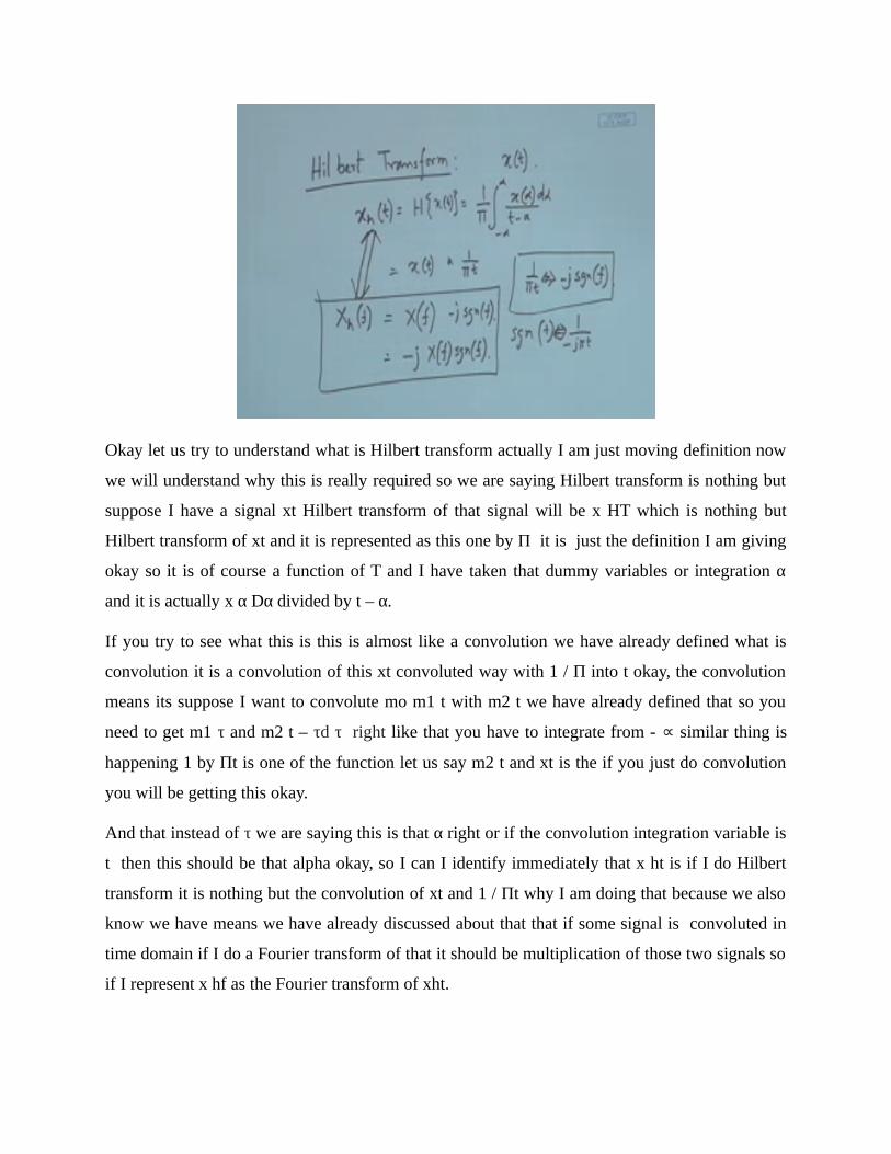
Okay let us try to understand what is Hilbert transform actually I am just moving definition now
we will understand why this is really required so we are saying Hilbert transform is nothing but
suppose I have a signal xt Hilbert transform of that signal will be x HT which is nothing but
Hilbert transform of xt and it is represented as this one by Π it is just the definition I am giving
okay so it is of course a function of T and I have taken that dummy variables or integration α
and it is actually x α Dα divided by t – α.
If you try to see what this is this is almost like a convolution we have already defined what is
convolution it is a convolution of this xt convoluted way with 1 / Π into t okay, the convolution
means its suppose I want to convolute mo m1 t with m2 t we have already defined that so you
need to get m1 τ and m2 t – τd τ right like that you have to integrate from - ∝ similar thing is
happening 1 by Πt is one of the function let us say m2 t and xt is the if you just do convolution
you will be getting this okay.
And that instead of τ we are saying this is that α right or if the convolution integration variable is
t then this should be that alpha okay, so I can I identify immediately that x ht is if I do Hilbert
transform it is nothing but the convolution of xt and 1 / Πt why I am doing that because we also
know we have means we have already discussed about that that if some signal is convoluted in
time domain if I do a Fourier transform of that it should be multiplication of those two signals so
if I represent x hf as the Fourier transform of xht.

Then that must be equal to the Fourier transforms has a Fourier transform of xf and Π 1/Πt we
have already defined the Fourier transform of that okay so 1/ Πt is actually the Fourier transform
is – jsgn f is something we have defined we have actually done this thing for sgn f t okay, and then
we know also that anything in time domain if I have a Fourier transform frequency domain also
the duality property I can use and if you just utilize those two things you will see that that signal
function the Fourier transform sgn f is actually a Fourier transform of - 1 /J Πt.
So from there we get dis conservation right so J Sgn f actually has a Fourier transform - jsgn f has
a Fourier transform of 1 / Πt so this is something I know so 1 / Πt the Fourier transform is - J
Sgn F so which is nothing but J xf Sgn f so this is something I know about the Hilbert transform
okay, so if I pass a signal through our Hilbert transform circuitry.
(Refer Slide Time: 08:08)
Suppose this is my Hilbert transform circuitry so if I pass x3 through it I will be getting xht now
I want to get the characteristics of this that is the hf of this one but that transfer function of this
one so I know that xhf if this is a the transfer function is HF that should be accept into hf right
so if I just go back to my previous relationship then what is my hf if this is the hilbert
transformer the hf must be j Sgn f right we have already proven that that x hf is accept into – jSgn f
therefore hf must be j signal s so this is actually the transfer function of a Hilbert transform.
Okay which I can write as minus J when F is greater than 0 and plus J when F is less than 0 right
because Sgn function we have already defined Sgn function is nothing but this okay, so whenever F

is greater than 0 it must be + 1 so this is + 1 and this is - 1 we have already defined that so this is
f so whenever F is positive it is + 1 so that must be - J and whenever F is negative its -1 so that
should be - J into - 1 that should be + J.
So this is what we get hf definition okay which I can further write as 1 into e to the power J Π /
2 and this we can write as1 ejΠ/2 right J can be written as this okay just put euler's theorem you
will see that okay because it will be Cos Π / 2 + J Sin Π /2 Cos Π / 2 will be 0 means if it is this
then it should be J Π / 2 J Sin Π /2 that should be J okay and this would be - e so if you just see
the transfer function looks like this any transfer function this is the transfer function any transfer
function must t have or amplitude.
This one plot and a frequency plot the amplitude if mod hf I wish to plot that should be constant
that is 1 if you take mod of this that is always 1 so h f has mod of HS that is always 1 and now
the phase one let us say θ hf I want to plot okay so what that should be that should be
whenever f is positive it should be θ is - Π by 2 so that should be - Π / 2 and this is +Π / 2 this Π
by 2 this is – Π/2 or right so that means whenever I have a positive frequency component it is
actually shifting the phase see the amplitude remains the same.
So amplitude I do not touch whenever I pass it through this whichever frequency component
suppose all tones I am passing so whichever frequency component is there for the positive
frequency component it is giving a Π / 2 phase shift and for the negative frequency component
because the negative frequency component will be exactly opposite it is again giving a Π/2 phase
shift so it is always giving a – Π/2 phase shift to every component every frequency component so
whichever it is the positive it is – Π/2.
In the negative because it is already either Π or - 5 so it is actually + Π/2 if you just take it out it
is again shifting by - Π/2 so it is actually always every frequency component that is give it is
giving Π/2 phase shift or I should say rather more concisely that – Π/2 phase shift, so this is a
typical circuitry which does not touches the amplitude but it just take every frequency and give
Π/2 phase shift so any frequency component if you it will just give you Π/2 phase shift here I
would like to point it out there are two different things we suppose we have a signal we give a
delay okay.
(Refer Slide Time: 12:47)
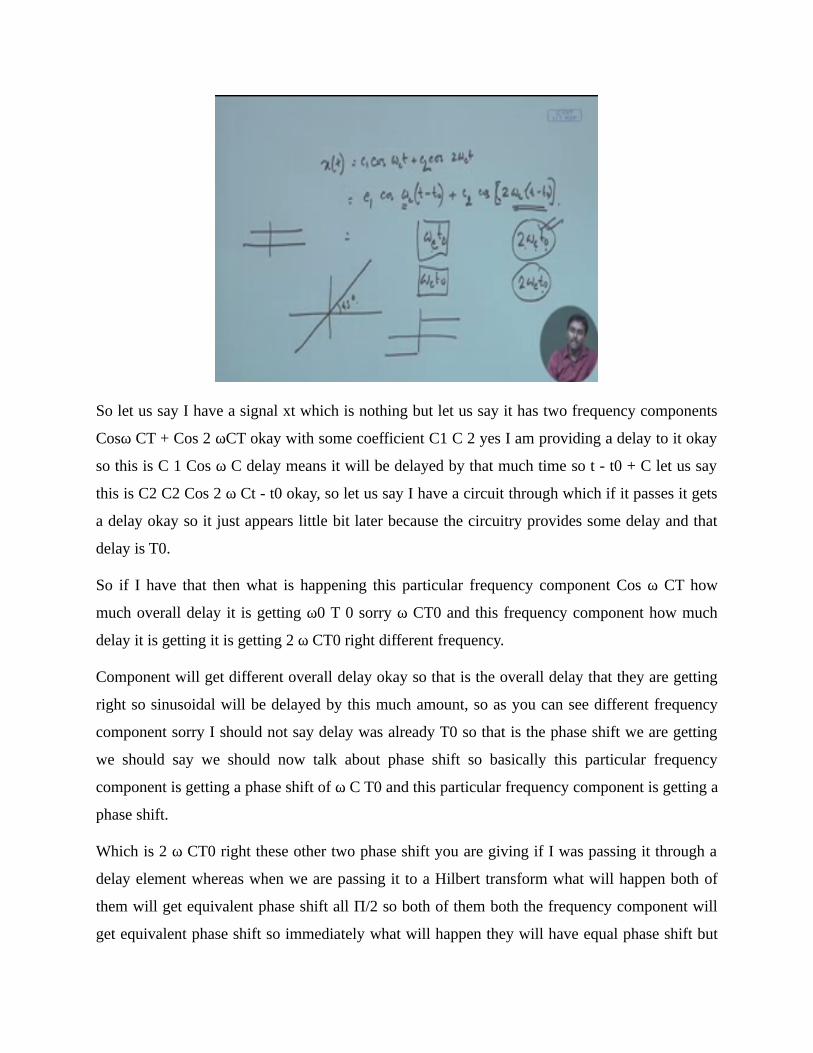
So let us say I have a signal xt which is nothing but let us say it has two frequency components
Cosω CT + Cos 2 ωCT okay with some coefficient C1 C 2 yes I am providing a delay to it okay
so this is C 1 Cos ω C delay means it will be delayed by that much time so t - t0 + C let us say
this is C2 C2 Cos 2 ω Ct - t0 okay, so let us say I have a circuit through which if it passes it gets
a delay okay so it just appears little bit later because the circuitry provides some delay and that
delay is T0.
So if I have that then what is happening this particular frequency component Cos ω CT how
much overall delay it is getting ω0 T 0 sorry ω CT0 and this frequency component how much
delay it is getting it is getting 2 ω CT0 right different frequency.
Component will get different overall delay okay so that is the overall delay that they are getting
right so sinusoidal will be delayed by this much amount, so as you can see different frequency
component sorry I should not say delay was already T0 so that is the phase shift we are getting
we should say we should now talk about phase shift so basically this particular frequency
component is getting a phase shift of ω C T0 and this particular frequency component is getting a
phase shift.
Which is 2 ω CT0 right these other two phase shift you are giving if I was passing it through a
delay element whereas when we are passing it to a Hilbert transform what will happen both of
them will get equivalent phase shift all Π/2 so both of them both the frequency component will
get equivalent phase shift so immediately what will happen they will have equal phase shift but

the delay will be different for different frequency element so that means if a constituent signal is
composed by multiple frequency element.
They will be separate we delayed so basically after Hilbert transform will not get back similar
signal whereas here the signal means composition will remain the same so there is a difference
between delay and this one it works almost similarly because it does not patch the amplitude it
just works on the phase okay for every frequency component but here in Hilbert transform you
are giving constant phase shift to every frequency component where in delay element you are
giving constant delay shift to every frequency element that means not equivalent phase it will be
actually linearly going growing with the frequency term if you just see the phase element is 2
ωCT 0 for 2 ωC.
Frequency it is actually ωCT 0 that means it gets doubled over here and whatever amount it was
having over here, so whenever your frequency gets doubled the phase shift will be doubled so if
you just plot a delay element that look like this whereas if you plot the Hilbert transform that will
also have amplitude spectrum as this mod HF will be this the delay element will be linear so
whatever is the frequency it will be just scaling with the frequency term okay if the frequency
doubles the delayed out double so it will be just linear with 450 angle okay.
Whereas for Hilbert transform you are constantly giving constant phase shift delay will be
different okay, so there the phase shifter is this so that is the difference between these two both of
them are delay element or a Hilbert transform both of them actually shifts different frequency
with either different phase or this one gives same phase shifting and they will not touch the
amplitude but there is a certain difference and that is why whenever you do Hilbert transform
you will have a deformation to the signal.
Whereas whenever you do a means you provide a delay element you will never see any
deformation to the signal this is the basic between these two okay and as you can see this is very
easy to realize okay, that is the circuit which is very easy to realize just keep on putting register
whenever it register means it will be just a propagation delay through it, so if you just keep on
putting a register or a transmission line your signal will come it will take some order time to
come out from this output.

So it will just be delayed version of the input signal so this is very easy to realize any real
circuitry will give you that as long as it is not touching the amplitude whereas this one is harder
to realize because it has a frequency selective delay different element gets different frequency
and even gets different amount of delay okay phase shift is same, so this is some circuitry which
is very difficult to realize okay so fine therefore.
(Refer Slide Time: 18:30)
If you wish to employ a circuitry which does this transformation, so all we have to do is we have
to understand that to do this I have to take every frequency component and give a phase shift
which is Π/2 okay, so original delay element will not do that you have to selectively take maybe
with a very narrow band pass filter, you have to take every frequency element and for everybody
you have to give Π/2phase shift okay so that is what you will have to do it means generally it is
a difficult circuit to realize there are techniques. But it is a difficult circuit to realize but we will see that there is a way to actually bypass this and
when first try to appreciate that where this is since why we are discussing this of course we

started talking about the bandwidth efficient modulation, so why this is required so will now will
probably try to appreciate that part okay , so first let us go back to my original proposition.
(Refer Slide Time: 19:32)
That a signal MF which is the frequency domain representation of some MT okay so let us say
this is my empty this signal can be represented as this Plus this is my M + F and this is my M - F
right where I represent M F as M + F plus M - F right, now if I wish to do a from D s be a
bandwidth efficient one which is generally originally called as SSPs see that means signal
sideband suppressed carrier so what I try to do is because I know one of them is actually giving
me the information so I wish to keep only one of them.
So when I do modulation at FC I just put one of them in the negative ass what should be
remaining it should be the other one because it needs to be symmetric otherwise the signal will
not be real and I cannot transmit a means complex signal in the air right that is not possible I
cannot even generate a complex signal this is just representation complex signals a
representation okay.

So if I wish to do that I should either represent it this way or I can represent it in another way
okay, so this is actually termed as upper sideband and this is termed as lower sideband because at
the positive half you can see this is actually the lower portion of it okay that is the negative part
of it so that is why this is called the lower sideband and this is where you are at the positive half
you are actually transmitting the upper sideband because there are two sideband.
So this I call as upper sideband and this I call as lower sideband so here at the positive half of the
frequency I am transmitting either upper sideband or lower sideband, so any of these two are
valid modulation if I can do this modulation first of all I have to be convinced that this
modulation is possible first let us try to see the mathematical treatment of it so what is this is
actually let us first try to represent this M + F okay and then we will try to represent this one so
what is M + F.
If M f is x UF what is Uf is nothing but this right so less than F less than 0 its 0almost like Ut
okay it is a unit step function and greater than F it is 1right so if I multiply this 1 with this
immediately what do I get I get only the positive of the M + F must be MF into us similarly M –f
if you –f is defined as this then it should be MF into u – f, now this you F the good part is can be
represented with respect to Sgn function because Sgn which is nothing but.
(Refer Slide Time: 22:55)
This thing okay if I add 1 to it then what will happen this is 1 this is - 1 if I add 1 this will go to 2
and this will be 0 and then put 1/2 so if this is my Sgn f if I write Sgn um f +1 into half that must be

my you f right so you f I can write this way why I am doing this because I want to deliberately
bring that Sgn f because I already know that J σ f is the representation of Hilbert transform or - J
Sgn f so I am deliberately bringing it okay, so therefore now I can write M + F which we have
written as M F into u F.
So that I can write now as MF into 1/2 Sgn f +1 right this I can write as half just MF + MF into σ
mess right I can write this way this is MF and what is this so if I just introduce a J over here - 1
by J means 1/ J should be taken over here, so I can write 1 by j into j MF Sgn s right if I introduce
a minus term over here that should be minus 1 by j multiplies above and down by j we will get
this is actually –J2 that is plus 1so you get just J over here right.
So I can write half this is MF plus or minus J this is m hf is not it there is a sign problem MF σ
mess I need a - J or that should equal so this is what we get ,so immediately I can see that this M
+ f can be represented as half of MF + J into the Hilbert transform of the message C so this can
be represented if you just do similar things.
(Refer Slide Time: 25:53)
You can see also my M - F can be represented as half into MF - J MHS you can also do this okay
just similar signal we just have to represent it okay this way, so now knowing these two things let
us try to represent this t SSB with USB okay, so what is this part this part is just M + this is the
plus half f translated at FC right so it must be M –f - FC and this part what is this is M -the
minus half translated asked minus FC so that must be F plus FC therefore.
(Refer Slide Time: 26:48)
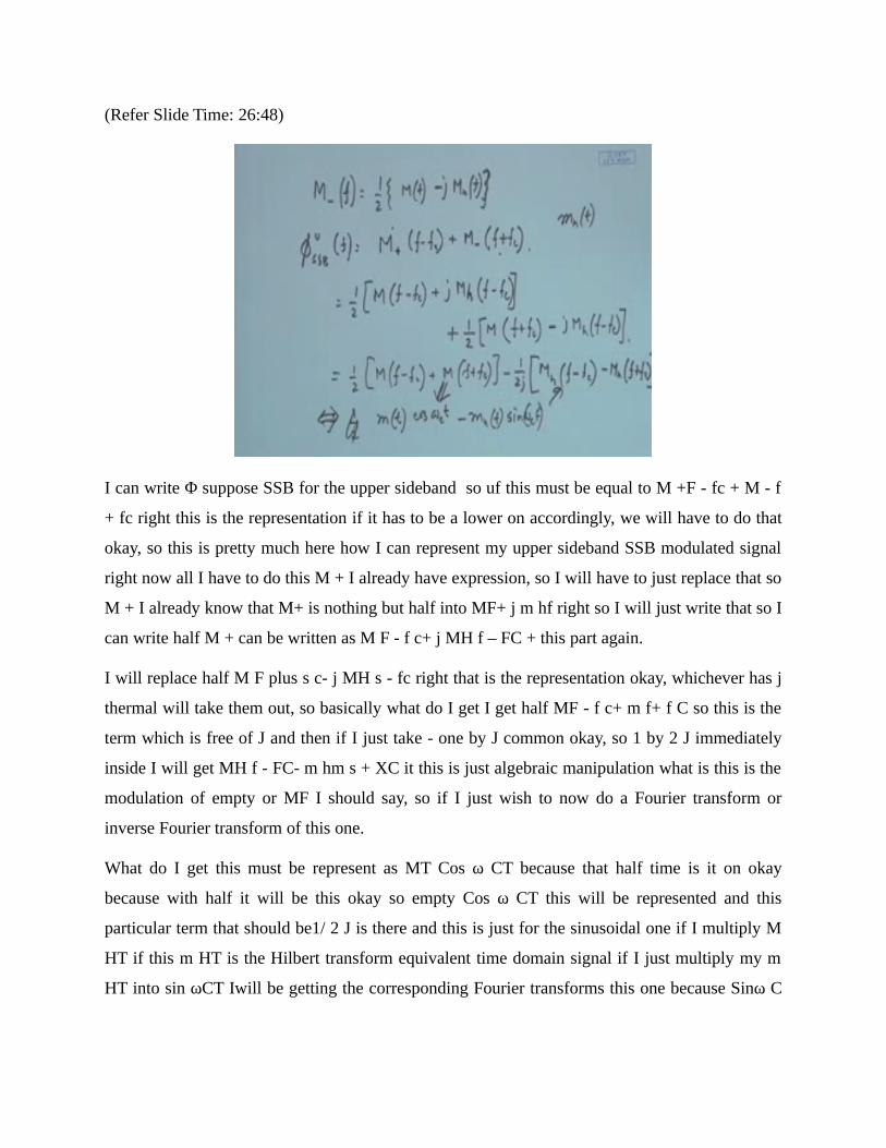
I can write Φ suppose SSB for the upper sideband so uf this must be equal to M +F - fc + M - f
+ fc right this is the representation if it has to be a lower on accordingly, we will have to do that
okay, so this is pretty much here how I can represent my upper sideband SSB modulated signal
right now all I have to do this M + I already have expression, so I will have to just replace that so
M + I already know that M+ is nothing but half into MF+ j m hf right so I will just write that so I
can write half M + can be written as M F - f c+ j MH f – FC + this part again.
I will replace half M F plus s c- j MH s - fc right that is the representation okay, whichever has j
thermal will take them out, so basically what do I get I get half MF - f c+ m f+ f C so this is the
term which is free of J and then if I just take - one by J common okay, so 1 by 2 J immediately
inside I will get MH f - FC- m hm s + XC it this is just algebraic manipulation what is this is the
modulation of empty or MF I should say, so if I just wish to now do a Fourier transform or
inverse Fourier transform of this one.
What do I get this must be represent as MT Cos ω CT because that half time is it on okay
because with half it will be this okay so empty Cos ω CT this will be represented and this
particular term that should be1/ 2 J is there and this is just for the sinusoidal one if I multiply M
HT if this m HT is the Hilbert transform equivalent time domain signal if I just multiply my m
HT into sin ωCT Iwill be getting the corresponding Fourier transforms this one because Sinω C

will have 1 by 2 J and then you have those modulation term so it will just be translated at + FC
and –system.
So basically what I can say now by looking at this spectrum so here I was doing all the
manipulation in the spectrum because I know that SSB means it should be half of the spectrum
right, so I can do the manipulation in the spectrum and I have the understanding of Hilbert
transform so this is what I of having so initially that spectrum I have represented with respect to
us from there I went to Sgn um F I knew that with Sgn um F I can represent it with respect to the
Hilbert transform and.
Then from there I could do some algebraic manipulation and I could see that actual SSB signal is
nothing but this so that means you take the message signal multiplied by cost and you take the
Hilbert transform the message signal multiplied by sign means subtract these, two you get your
SSB signal so generation of SSB just comes from this we have seen the frequency domain
representation now in time domain we can immediately get the representation okay, but then in
the next class what we will try to do try to appreciate.
That this MHT we have already talked about that circuitry to do just 900C phase shift for each
component is a very difficult one we will try to devise a circuit which is known as wave a circuit
which does it very nicely, okay so we will try to see that and try to see the corresponding
mathematical representation of that thank you.