NPPD Gerald Gentleman Station DCS Upgrade
28
NPPD Gerald Gentleman Station DCS Upgrade Power Gen Center of Excellence: Paul Wiley, Alex Turner
-
Upload
honeywell-process-solutions -
Category
Technology
-
view
159 -
download
0
Transcript of NPPD Gerald Gentleman Station DCS Upgrade

NPPD Gerald Gentleman Station DCS Upgrade Power Gen Center of Excellence: Paul Wiley, Alex Turner

2 © 2015 Honeywell International All Rights Reserved
Nebraska Public Power District (NPPD) - Overview
• NPPD is Nebraska’s largest Electric Utility, HQ in Columbus, NE • Fleet is a diverse mix capable of producing > 3,000 MW:
• Cooper Nuclear Station - 810 MW • Gerald Gentleman Station - 2 coal fired units at 1,365MW * • Sheldon Station – 2 coal fired units at 225MW • Beatrice Station – 2 Gas fired CC units at 250MW * • Canaday Station – 1 Gas fired unit at 119MW * • 3 Peaking Plants (GT’s) totaling approximately 155 MW
capacity • 3 Hydro Plants totaling approximately 32MW capacity • NPPD owns, operates and purchases power from several wind
farms including NPPD’s Ainsworth with 36, 1.65MW turbines • NPPD also operates a network of irrigation canals, dams and
reservoirs along a 150 mile stretch of the Platte River
Honeywell DCS *

3 © 2015 Honeywell International All Rights Reserved
Overview of Projects Schedule
Overview of Projects Schedule: Unit 1 BCS – Spring 2011 Unit 2 BCS – Spring 2012 Unit 1 BMS – Spring 2013 Unit 2 BMS – Spring 2014 Unit 1 ILS – Spring 2015 Unit 2 ILS – Spring 2016 Units 1 & 2 Sootblowing Air Compressor upgrades 2013/14 NOTE: All DCS upgrades completed on schedule during Spring outages with no impact to NPPD Outage Schedules
Typical Results… Projects were completed on
Schedule Projects were completed on
Budget Unique FEED Process was Utilized:
• Drives out risk early in project execution cycle
• Minimizes Change Orders • Facilitates collaboration • Full range of Projects Services
and Support Good Customer Satisfaction

4 © 2015 Honeywell International All Rights Reserved
Design Basis
Configuration Design Basis: • Control Strategies are programmed into the redundant C300 controllers • Control Logic is developed and implemented using the existing Functional
Descriptions and P&ID’s • Updates added based on Honeywell’s latest design standards for C300
control Algorithms / functionality • Controls and graphics for operator interface developed by Honeywell and
reviewed jointly with NPPD • Extensive involvement by NPPD Ops with Graphics development
enhanced final versions. • Control strategies, logic and graphics were reviewed with NPPD during
two (2) Design Review Meetings – PDR and DDR • All strategies fully tested, reviewed with and approved by NPPD at FAT
prior to the installation on site

5 © 2015 Honeywell International All Rights Reserved
Honeywell Deliverables
Deliverables by Honeywell to NPPD: • Experion Documentation Set including System Design Manuals (SDM)
and Bill of Material • Project Plan, Schedule, bi-weekly Status minutes, Quarterly Status Report • Control Logic drawings generated from the Experion PKS Control Builder
software. • I/O database with the necessary details for terminating the wires to the
DCS • Hardware and system drawings - cabinets, architecture, power/grounding,
network drawings • HMI Web Displays per the Honeywell Proposal and agreements -
documented at project Design Review meetings and other correspondence including Graphics Standards Manual
• Factory Acceptance Test (FAT) and Site Acceptance Test (SAT) Procedures
• Final project Functional Descriptions and As Built Drawings

6 © 2015 Honeywell International All Rights Reserved
Project Execution Process
All Honeywell projects follow our Global Project Methodology (GPM). GPM requires a project plan. The project plan for NPPD’s projects was provided to NPPD for review and comment. The project plan includes the following major sections: 1. Scope of Work Summary 2. Contractual Information 3. Experion System Controls 4. Project Deliverables 5. Honeywell Engineering Scope of Work 6. Risk and Opportunity Plan and Objectives 7. Health, Safety & Environment (HSE) Plan and Objectives
7 © 2015 Honeywell International All Rights Reserved
Project Execution Process
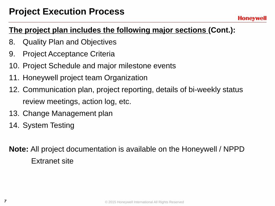
The project plan includes the following major sections (Cont.): 8. Quality Plan and Objectives 9. Project Acceptance Criteria 10. Project Schedule and major milestone events 11. Honeywell project team Organization 12. Communication plan, project reporting, details of bi-weekly status
review meetings, action log, etc. 13. Change Management plan 14. System Testing
Note: All project documentation is available on the Honeywell / NPPD
Extranet site

8 © 2015 Honeywell International All Rights Reserved
GGS Unit 1 BCS Upgrade Project – Spring 2011
Upgrade 12 existing HPM controllers to C300: • Unit Master • Mills ADEG; Mills BCFH • OFA/AR for ABEF and OFA/AR CDHG • Air Flow • Feedwater • Miscellaneous Control • DAS Digitals • DAS Analogs 1, DAS Analogs 2 • Annunciator Digitals
Upgrade Included 5 New C300 controllers (C Series IO): • Baghouse (requires 2 red C300 controllers) • Ash Handling • Soot Blowers • SOE C300

9 © 2015 Honeywell International All Rights Reserved
GGS Unit 1 BCS Upgrade Project – Spring 2011 Additional Equipment and Services:
• 5 Quad Icon Control Room Op Stations, 1 Op Station driving dual 42 in. monitors • 3 Eng Stations, 1 with 21 inch dual displays, 2 with dual 21 in. and 1 42 in. monitors • Experion Server included 1 redundant rack mounted set of servers with ESVT • 1 ACET • Experion Backup and Restore • AMCL to Control Modules • Advanced Alarm Management included 1 server and associated software • PHD Uniformance for PHD Collector • Network cabinet with 2 ea Cisco Switches and 2 ea 48 port patch panels

10 © 2015 Honeywell International All Rights Reserved
GGS Unit 2 BCS Upgrade Project – Spring 2012
Upgrade 11 existing HPM controllers to C300: • Unit Master • Mills B&D; Mills AEF; Mills CGH • Air Flow • Feedwater • Miscellaneous Control • DAS Digitals • DAS Analogs 1, DAS Analogs 2 • Annunciator Digitals
Upgrade Included 7 New C300 controllers (C Series IO): • Baghouse (requires 2 red C300 controllers) • Ash Handling • Soot Blowers • OFA/AR for ABEF • OFA/AR for CDGH • SOE C300 (Included ATS CM’s/SCM’s)
11 © 2015 Honeywell International All Rights Reserved
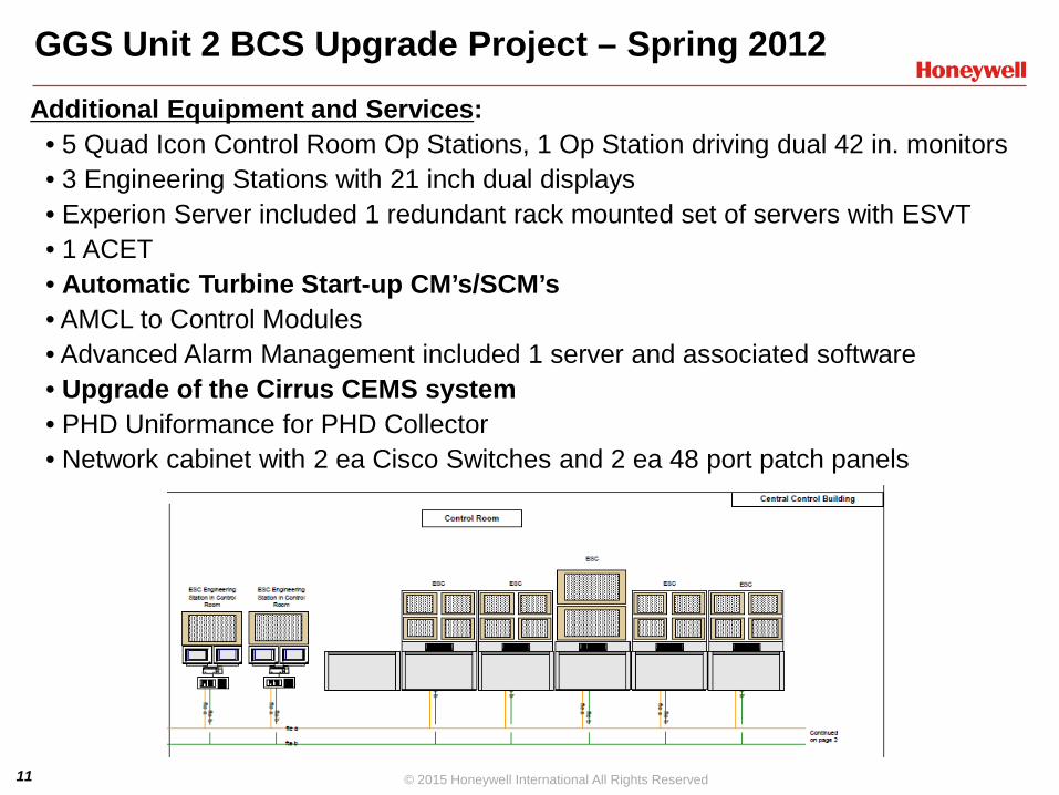
GGS Unit 2 BCS Upgrade Project – Spring 2012
Additional Equipment and Services: • 5 Quad Icon Control Room Op Stations, 1 Op Station driving dual 42 in. monitors • 3 Engineering Stations with 21 inch dual displays • Experion Server included 1 redundant rack mounted set of servers with ESVT • 1 ACET • Automatic Turbine Start-up CM’s/SCM’s • AMCL to Control Modules • Advanced Alarm Management included 1 server and associated software • Upgrade of the Cirrus CEMS system • PHD Uniformance for PHD Collector • Network cabinet with 2 ea Cisco Switches and 2 ea 48 port patch panels

12 © 2015 Honeywell International All Rights Reserved
GGS Unit 1 & 2 BMS Upgrade Projects – Spring 2013/2014
Upgrade of 2 existing FSC controllers to 2 C300 controllers: • Common BMS Functions, Mills were split between the 2 C300 controllers • Five (5) cabinets to house the C300 controllers and Series C IO • NFPA 85 Trip Testing • External Watchdog Timer Solid-state relays for C300 Controllers
Additional Equipment and Services :
• 3 Eng Stations with 21 inch dual displays configured as (2 ESC, 1 ESF) • Experion Server included 1 red. rack mounted set of servers with ESV • PHD Uniformance for PHD Collector and 1 ACE • Network cabinet with 2 ea Cisco Switches and 2 ea 48 port patch panels • On process migration of Unit 1 to Experion Release R410; Off process
migration to R410 for U2 in 2014 NOTES: • Honeywell also provided a review of the new BMS logic by a Nebraska certified PE. A white paper was provided certifying that the new BMS logic emulates the existing BMS logic.
• Honeywell and NPPD jointly developed a Front End Engineering Design (FEED) process which was used on this project.

13 © 2015 Honeywell International All Rights Reserved
GGS Unit 1 & 2 ILS Upgrade Projects – Spring 2015/2016
Upgrade of 2 existing FSC controllers to 2 C300’s for the ILS: • Common Interface Logic System (ILS) Functions • IO split between the 2 C300 controllers • Seven (7) cabinets to house the C300 controllers and Series C IO (Unit 1) • Twelve (12) cabinets to house the C300 controllers and Series C IO (Unit 2)
Additional Equipment and Services : • Removed LCN completely (Unit 1 in 2015, Unit 2 in 2016) • Also Hardware Refresh consisting of Op Stations, Servers, ACE, PHD • Planned migration of both units to Experion R431 in Spring 2016
NOTES: • Honeywell also provided a review of the new ILS logic by a Nebraska certified
PE. A white paper was provided certifying that the new ILS logic emulates the existing ILS logic.
• Honeywell and NPPD jointly developed a Front End Engineering Design (FEED) process which was used on this project.

14 © 2015 Honeywell International All Rights Reserved
Detailed FEED Overview
• NPPD and Honeywell have a long standing relationship and are in the midst of a major DCS modernization program to upgrade existing Honeywell TPS controls to Experion at Gerald Gentleman Station
• Detailed FEED includes all upfront HW engineering including: • Final “Issued for Construction” System Design Manual
• Final Bill of Materials ready for hardware order on factory
• Detailed analysis of Logics including a PE review if required
15 © 2015 Honeywell International All Rights Reserved
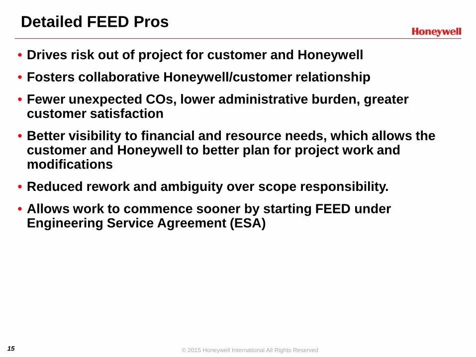
Detailed FEED Pros
• Drives risk out of project for customer and Honeywell • Fosters collaborative Honeywell/customer relationship • Fewer unexpected COs, lower administrative burden, greater
customer satisfaction • Better visibility to financial and resource needs, which allows the
customer and Honeywell to better plan for project work and modifications
• Reduced rework and ambiguity over scope responsibility. • Allows work to commence sooner by starting FEED under
Engineering Service Agreement (ESA)
16 © 2015 Honeywell International All Rights Reserved
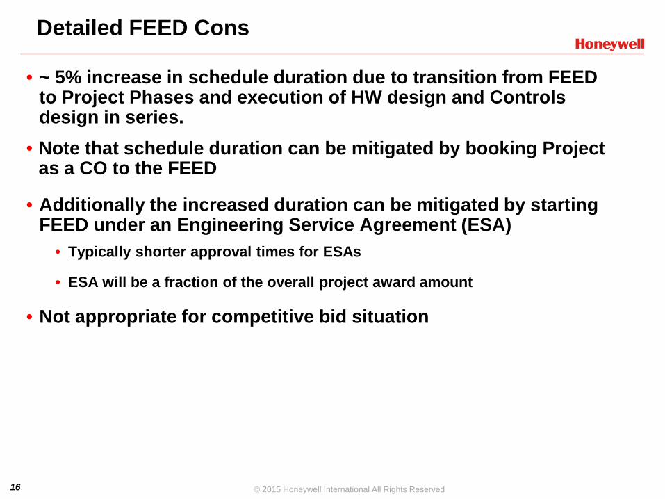
Detailed FEED Cons
• ~ 5% increase in schedule duration due to transition from FEED to Project Phases and execution of HW design and Controls design in series.
• Note that schedule duration can be mitigated by booking Project as a CO to the FEED
• Additionally the increased duration can be mitigated by starting FEED under an Engineering Service Agreement (ESA)
• Typically shorter approval times for ESAs
• ESA will be a fraction of the overall project award amount
• Not appropriate for competitive bid situation

17 © 2015 Honeywell International All Rights Reserved
Example Schedule and Process 2015 Outage
Milestones Date • Award ESA (Paid FEED study) September 2013 • FEED KO and Site Walkdown October 2013 • Produce IFA Deliverables Oct – Dec 2013 • Midcourse Review Meeting January 2014 • Deliver Final IFC Deliverables February 2014 • Deliver Firm Fixed Proposal March 2014 • Contract Review Meeting March 2014 • Book Contract for Project as CO April 2014 • Order HW and Execute Project April 14 – May 15

Budgetary FEED + Project
Firm Proposal for FEED (ESA) – FEED
Phase
KO FEED and Site Walkdown
Midcourse Review Meeting
Issue Firm Fixed Price Proposal –
Project Phase
Contract Review Meeting
Book Project as CO to FEED
Commence Project Phase
+25/-10% Price for FEED is Approx 30% of Budgetary total
FEED Duration about 5-6 Mo.
All Issued for Approval (IFA) Deliverables are Reviewed in Person with Customer. Customer issues approval of design. Fully Approved System
Design (IFC) Low Risk
Contract Reviewed in Person with IFC Design Documents. All requirements are
fully understood by both parties.
Allows for quick booking and immediate commencement
of project.
SDM and BoM are complete and fully approved. Project team can order HW and
commence work immediately.
Start
Detailed FEED Study Execution Cycle
18

19 © 2015 Honeywell International All Rights Reserved
NPPD Projects - Lesson's Learned
Flexibility is required to work around unforeseen events Continuity of Project team helped to address issues and
smooth the transitions from project to project The FEED process really works Excellent and frequent communication

20 © 2015 Honeywell International All Rights Reserved
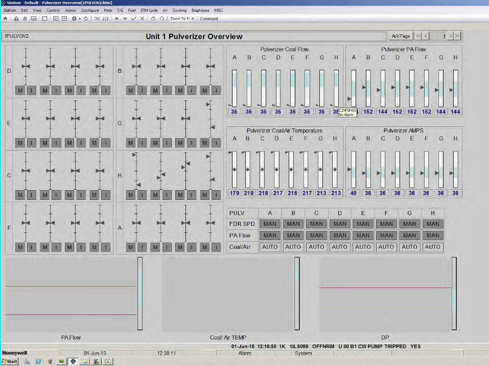
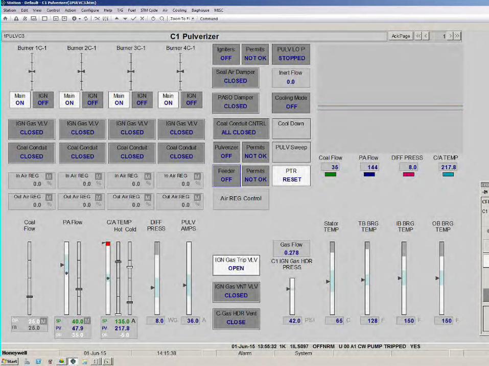
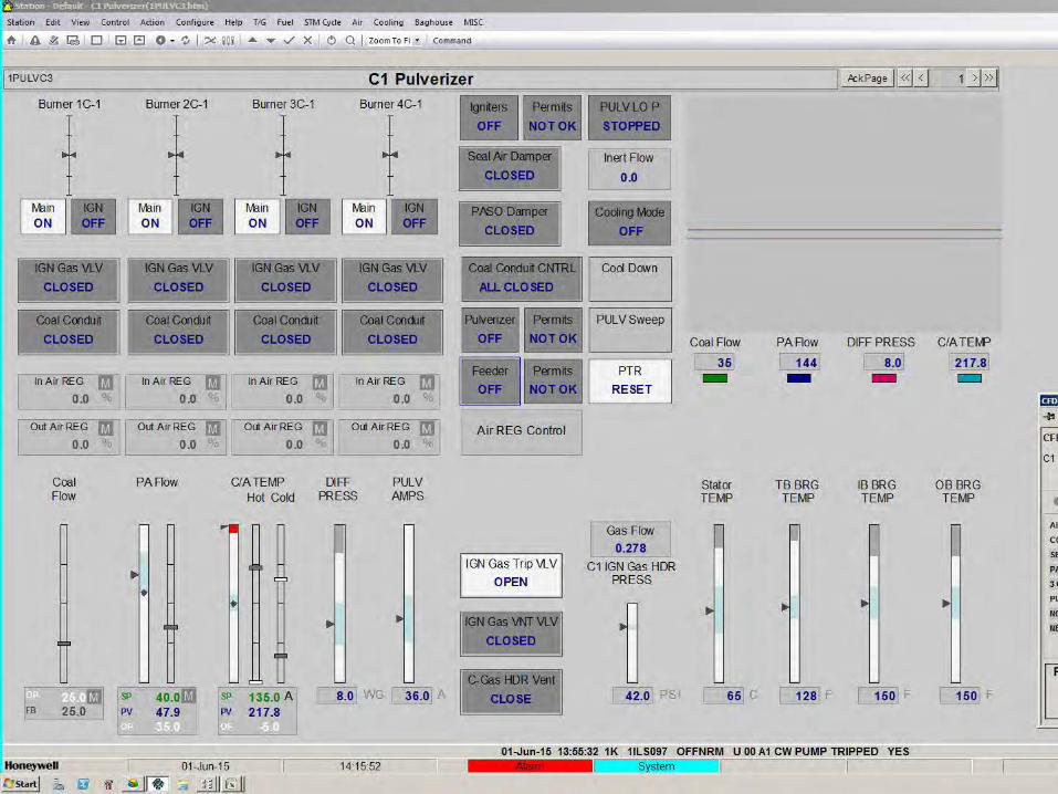
Sample Graphics
Unit 1 Pulverizer Overview Unit 1 Turbine / Generator Unit 1 Unit Master C1 Pulverizer – Showing C1 Feeder Faceplate C1 Pulverizer – Showing C1 Feeder Faceplate with Permits C1 Pulverizer – Showing C1 Feeder Faceplate with Interlocks (and showing first out)
Unit 1 Electrical Distribution System Overview Unit 1 Sootblower System Overview
21 © 2015 Honeywell International All Rights Reserved
Sample Graphics

22 © 2015 Honeywell International All Rights Reserved
Sample Graphics

23 © 2015 Honeywell International All Rights Reserved
Sample Graphics
24 © 2015 Honeywell International All Rights Reserved
Sample Graphics
25 © 2015 Honeywell International All Rights Reserved
Sample Graphics

26 © 2015 Honeywell International All Rights Reserved
Sample Graphics

27 © 2015 Honeywell International All Rights Reserved
Sample Graphics

28 © 2015 Honeywell International All Rights Reserved
Sample Graphics