NPDES Compliance Inspection Manual - United … Measurement System Evaluation.....121 Closed Conduit...
17
NPDES Compliance Inspection Manual Chapter 6 EPA Publication Number: 305-K-17-001 Interim Revised Version, January 2017
Transcript of NPDES Compliance Inspection Manual - United … Measurement System Evaluation.....121 Closed Conduit...

NPDES Compliance Inspection Manual
Chapter 6
EPA Publication Number: 305-K-17-001 Interim Revised Version, January 2017
U.S. EPA Interim Revised NPDES Inspection Manual | 2017
Chapter 6 – Page 117
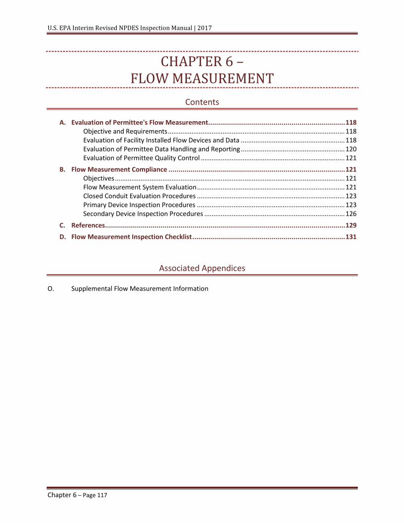
CHAPTER 6 – FLOW MEASUREMENT
Contents
A. Evaluation of Permittee's Flow Measurement ..................................................................... 118 Objective and Requirements ................................................................................................. 118 Evaluation of Facility Installed Flow Devices and Data ......................................................... 118 Evaluation of Permittee Data Handling and Reporting ......................................................... 120 Evaluation of Permittee Quality Control ............................................................................... 121
B. Flow Measurement Compliance ......................................................................................... 121 Objectives .............................................................................................................................. 121 Flow Measurement System Evaluation ................................................................................. 121 Closed Conduit Evaluation Procedures ................................................................................. 123 Primary Device Inspection Procedures ................................................................................. 123 Secondary Device Inspection Procedures ............................................................................. 126
C. References ......................................................................................................................... 129 D. Flow Measurement Inspection Checklist ............................................................................. 131
Associated Appendices
O. Supplemental Flow Measurement Information

U.S. EPA Interim Revised NPDES Inspection Manual | 2017
Chapter 6 – Page 118
A. EVALUATION OF PERMITTEE'S FLOW MEASUREMENT OBJECTIVE AND REQUIREMENTS
To comply with the permit requirements established under the National Pollutant Discharge Elimination System (NPDES), the permittee must accurately determine the quantity of wastewater being discharged. Discharge flow measurement is an integral part of the NPDES program, it is important that the inspector evaluate the accuracy of the measurement.
In addition to providing usable information for enforcement purposes, flow measurement serves to:
• Provide data for pollutant mass loading calculations. • Provide operating and performance data on the wastewater treatment plant. • Compute treatment costs, based on wastewater volume. • Obtain data for long-term planning of plant capacity, versus capacity used. • Provide information on Infiltration and Inflow (I/I) conditions, and the need for cost-
effective I/I correction.
A Flow Measurement Inspection Checklist for the inspector's use appears at the end of this chapter.
EVALUATION OF FACILITY INSTALLED FLOW DEVICES AND DATA
There are two types of wastewater flow: closed-channel flow and open-channel flow. Closed-channel flow occurs under pressure in a liquid-full conduit (usually a pipe). The facility will usually have a metering device inserted into the conduit that measures flow. Examples of closed-channel flow measuring devices are the Venturi meter, the Pitot tube, the paddle wheel, the electromagnetic flowmeter, Doppler, and the transit-time flowmeter. In practice, closed-channel flow is normally encountered between treatment units in a wastewater treatment plant, where liquids and/or sludges are pumped under pressure.
Open-channel flow occurs in conduits that are not liquid-full. Open-channel flow is partially full pipes not under pressure. Open-channel flow is the most prevalent type of flow at NPDES-regulated discharge points. Open-channel flows are typically measured using primary and secondary devices. Primary devices are standard hydraulic structures, such as flumes and weirs that are inserted in the open channel. Inspectors can obtain accurate flow measurements merely by measuring the depth of liquid (head) at the specific point in the primary device. In a weir application, for example, the flow rate is a function of the head of liquid above the weir crest.
Facilities use secondary devices in conjunction with primary devices to automate the flow measuring process. Typically, secondary devices measure the liquid depth in the primary device and convert the depth measurement to a corresponding flow, using established mathematical relationships. Examples of secondary devices are gauges, floats, ultrasonic transducers, bubblers, and transit-time flowmeters. A recorder generally measures the output of the

U.S. EPA Interim Revised NPDES Inspection Manual | 2017
Chapter 6 – Page 119
secondary device transmitted to a recorder and/or totalizer to provide instantaneous and historical flow data to the operator. Outputs may also be transmitted to sampling systems to facilitate flow proportioning. Appendix O, “Supplemental Flow Measurement Information,” contains further information on flow measurement devices.
The inspector must assure that the permittee obtains accurate wastewater flow data to calculate mass loading (quantity) from measured concentrations of pollutants discharged as required by many NPDES permits. The permittee must produce data that meet requirements in terms of precision and accuracy. Precision refers to data reproducibility or the ability to obtain consistent data from repeated measurements of the same quantity. Accuracy refers to the agreement between the amount of a component measured by the test and the amount present.
The accuracy of flow measurement (including both primary and secondary devices) varies widely with the device, its location, environmental conditions, and other factors such as maintenance and calibration. Faulty fabrication, construction, and installation of primary devices are common sources of errors. Improper calibration, misreading, and variation in the speed of totalizer drive motors are major errors related to secondary devices (see Appendix O, “Supplemental Flow Measurement Information”). When evaluating facility installed devices, the inspector should do the following:
• Verify that the facility has installed primary and/or secondary devices according to the manufacturer's manual instructions.
• Inspect the primary device for evidence of corrosion, scale formation, or solids accumulation that may bias the flow measurement.
• Verify that weirs are level, plumb, and perpendicular to the flow direction.
• Verify that flumes are level and smooth-finished, the throat walls (narrowed section of flume) are plumb, and the throat width is the standard size intended.
• Inspect historical records (i.e., strip charts and logs) for evidence of continuous flow measurements and for routine and maintenance operations schedules. Compare periods of missing data with maintenance logs for explanations of measuring system problems.
• Observe the flow patterns near the primary device for excessive turbulence, velocity, or accumulating foam. The flow lines should be straight.
• Ensure that the flow measurement system or technique being used measures the entire wastewater discharge as required by the NPDES permit. Inspect carefully the piping to determine whether there are any wastewater diversions, return lines, or bypasses around the system. Make sure the system meets the permit requirement, such as instantaneous or continuous, daily, or other time interval measures. Note anomalies in the inspection report.
• Verify that the site chosen for flow measurement by the facility is appropriate and is in accordance with permit requirements.

U.S. EPA Interim Revised NPDES Inspection Manual | 2017
Chapter 6 – Page 120
• Verify that the site chosen by the facility for flow measurement is suitable for the type of discharge, flow range, suspended solids concentration, and other relevant factors.
• Determine if the facility has closed-channel flow measuring devices where the pipe is always full. If these devices are used, then there must also be a means for the permittee and regulatory agencies/inspector to verify the accuracy of these meters. Primary open-channeled flow measuring devices such as weirs and flumes should be used in an open-channel segment above or below the closed-channel segment to verify the flow measured by the closed-channel flow measuring devices.
• Verify that the facility uses appropriate tables, curves, and formulas to calculate flow rates.
• Review and evaluate calibration and maintenance programs for the discharger's flow measurement system. The permit normally requires the facility to check the calibration regularly by the permittee. The facility must ensure that their flow measurement systems are calibrated by a qualified source at least once a year to ensure their accuracy. Lack of such a program is considered unacceptable for NPDES compliance purposes.
• Verify that the facility calibrates secondary flowmeter systems to be within 10 percent of the primary flow measurement system.
• Verify that primary and secondary devices are adequate for normal flow as well as maximum expected flows. Note whether the flow measurement system can measure the expected range of flows.
• Collect accurate flow data during inspection to validate self-monitoring data collected by the permittee.
• The facility must install a flow measuring system that has the capability of routine flow verification by the permittee or appropriate regulatory personnel.
EVALUATION OF PERMITTEE DATA HANDLING AND REPORTING
The permittee or facility must keep flow measurement records for a minimum period of three years. Many flow-measuring devices produce a continuous flowchart for plant records. Flow records should contain date, flow, time of reading, and operator's name. The facility should record maintenance, inspection dates, and calibration data.
The inspector should review the permittee's records and note the presence or absence of data such as:
• Frequency of routine operational inspections. • Frequency of maintenance inspections. • Frequency of flowmeter calibration (should be as specified in permit, generally at least
once per year). • Irregularity or uniformity of flow.

U.S. EPA Interim Revised NPDES Inspection Manual | 2017
Chapter 6 – Page 121
EVALUATION OF PERMITTEE QUALITY CONTROL
The inspection should evaluate the following quality control issues during a compliance inspection to ensure:
• Proper operation and maintenance of equipment • Accurate records • Sufficient inventory of spare parts • Valid flow measurement techniques • Precise flow data • Adequate frequency of calibration checks
Evaluate precision of float driven flow meters when flows are stable. Push the float gently downward, hold for 30 seconds, then allowed to return normally. The recorded flow rate should be the same before and after the float was moved. Evaluate accuracy by measuring the instantaneous flow rate at the primary device used at the facility and comparing the value against the value on the meter, graph, integrator, or company record. The difference between two stable totalizer readings (flow is steady for 10 minutes or more) should not exceed ±10 percent of the instantaneous flow measured at the primary device. Note that most flow measurement systems have both an instantaneous meter readout and a totalizer. Both devices should agree, but that is not always the case due to electrical and other various malfunctions in the flow measuring system. In most cases, the totalizer reading will be what is reported by the permittee. If this is the case, then that device should be checked for accuracy and the permittee’s flow measuring system rated accordingly.
In addition, the inspector can evaluate accuracy by installing a second flow measurement system, sometimes referred to as a reference system. Agreement in measured flow rates between the two systems should be within ±10 percent of the reference rate if all conditions are as recommended for the systems.
B. FLOW MEASUREMENT COMPLIANCE OBJECTIVES
The current NPDES program depends heavily on the permittee's submittal of self-monitoring data. The flow discharge measured during the NPDES compliance inspection should verify the flow measurement data collected by the permittee, support any enforcement action that may be necessary, and provide a basis for reissuing or revising the NPDES permit.
FLOW MEASUREMENT SYSTEM EVALUATION
The responsibility of the inspector includes collecting accurate flow data during the inspection and validating data collected during the permittee's self-monitoring.
The NPDES inspector must check both the permittee's flow data and the flow measurement system to verify the permittee's compliance with NPDES permit requirements. If a flow-measuring device is located below ground or in confined space, inspectors are not to enter

U.S. EPA Interim Revised NPDES Inspection Manual | 2017
Chapter 6 – Page 122
confined spaces unless trained and permitted to do so. When evaluating a flow measurement system, the inspector should consider and record findings on the following:
• Whether the system measures the entire discharge flow.
• The system's accuracy and good working order. This will include a thorough physical inspection of the system and comparison of system readings to actual flow or those obtained with calibrated portable instruments.
• The need for new system equipment.
• The existence or absence of a routine calibration and maintenance program for flow measurement equipment.
If the permittee's flow measurement system is accurate within ±10 percent, the inspector should use the installed system. If the flow sensor or recorder is found to be inaccurate, the inspector should determine whether the equipment can be corrected in time for use during the inspection. If the equipment cannot be repaired in a timely manner, use the portable flow sensor and recorder used to assess the accuracy of the permittee's system for the duration of the inspection. If nonstandard primary flow devices are being used, request the permittee to supply data on the accuracy and precision of the method being employed.
For flow measurement in pipelines, the inspector may use a portable flowmeter. The inspector should select a flowmeter with an operating range wide enough to cover the anticipated flow to be measured. The inspector should test and calibrate the selected flowmeter before use. The inspector should select the site for flow measurement according to permit requirements and install the selected flowmeter according to the manufacturer's specifications. The inspector should use the proper tables, charts, and formulas as specified by the manufacturer to calculate flow rates.
Four basic steps are involved in evaluating the permittee's flow measurement system:
• Physical inspection of the primary device • Physical inspection of the secondary device and ancillary equipment • Flow measurement using the primary/secondary device combination of the permittee • Certification of the system using a calibrated, portable instrument
Facilities with a closed pipe flow measurement system present a challenge to the inspector. Have the facility personnel explain the operation of the system and how they calibrate the flow measurement system. Check if it is calibrated yearly at a minimum. It is suggested that the facility conduct periodic monthly checks of the flow measurement system. The inspector can do a calibration of the closed pipe flow measurement systems in the following ways:
1. If an open-channel primary device is maintained at the facility the inspector can obtain an instantaneous head reading to verify the accuracy of the closed channel flow measuring system. Flow should be within ±10 percent of the closed channel system.

U.S. EPA Interim Revised NPDES Inspection Manual | 2017
Chapter 6 – Page 123
2. The inspector can use a portable flow meter (usually consists of two strap-on sensors that mount on the pipe and utilize the Doppler principle) to verify the accuracy of the facility’s flow measurement system by conducting side-by-side comparisons. Flow should be within ±10 percent.
3. Confirm that the calibration procedure demonstrated by the facility’s calibration personnel is adequate.
The following sections present procedures for inspecting the more common types of primary and secondary devices, for measuring flow using common permanent and portable systems, and for evaluating flow data. Please note that the number of primary/secondary device combinations is limitless; therefore, it is not feasible to provide procedures for all systems. When encountering systems other than those discussed here the inspector should consult the manufacturer’s manual or facility personnel for advice on how the flow-measurement system operates before preparing a written inspection procedure.
CLOSED CONDUIT EVALUATION PROCEDURES
For closed-channel flow, the inspector performs the following checks on the system:
• Check for straight pipe runs of sufficient length both upstream (8–10 inches) and downstream (4–6 inches) of the measuring device.
• Determine if the meter size is appropriate for pipe diameter and flow ranges based on equipment manufacturer literature.
• Determine frequency of cleaning of pressure taps.
PRIMARY DEVICE INSPECTION PROCEDURES
The two most common open-channel primary devices are sharp-crested weirs and Parshall flumes. Common sources of error when using them include the following:
• Faulty fabrication—weirs may be too narrow or not "sharp" enough. Flume surfaces may be rough, critical dimensions may exceed tolerances, or throat walls may not be vertical.
• Improper installation—the facility may install weirs and flumes too near pipe elbows, valves, or other sources of turbulence. The devices may be out of level or plumb.
• Sizing errors—the primary device's recommended applications may not include the actual flow range.
• Poor maintenance—primary devices corrode and deteriorate. Debris and solids may accumulate in them Specific inspection procedures for the sharp-crested weir, the Parshall flume, and the Palmer-Bowlus flume devices follow.
Sharp-Crested Weir Inspection Procedures • Inspect the upstream approach to the weir.
– Verify that the weir is perpendicular to the flow direction.

U.S. EPA Interim Revised NPDES Inspection Manual | 2017
Chapter 6 – Page 124
– Verify that the approach is a straight section of conduit with a length at least 20 times the maximum expected head of liquid above the weir crest.
– Observe the flow pattern in the approach channel. The flow should occur in smooth stream lines without velocity gradients and turbulence.
– Check the approach, particularly near the weir, for accumulated solids, debris, or oil and grease. The approach must have no accumulated matter.
• Inspect the sharp-crested weir.
– Verify that the crest of the weir is level across the entire conduit traverse. – Measure the width of the weir crest. The edge of the weir crest should be no more
than 1/8-inch thick. – Make certain the weir crest corresponds to zero-gauge elevation (zero output on the
secondary device). – Measure the angle formed by the top of the crest and the upstream face of the weir.
This angle must be 90 degrees. – Measure the chamfer (beveled edge) on the downstream side of the crest. The
chamfer should be approximately 45 degrees. – Visually survey the weir-bulkhead connection for evidence of leaks or cracks that
permit bypass. – Measure the height of the weir crests above the channel floor. The height should be
at least twice the maximum expected head (2H) of liquid above the crest. – Measure the width of the end contraction. The width should be at least twice the
maximum expected head (2H) of the liquid above the crest. – Confirm the location of the head-measuring device. The device should be located
upstream of the weir at a point at least four times the maximum head. – Inspect the weir for evidence of corrosion, scale formation, or clinging matter. The
weir must be clean and smooth. – Observe flow patterns on the downstream side of the weir. Check for the existence
of an air gap (ventilation) immediately adjacent to the downstream face of the weir. Ventilation is necessary to prevent a vacuum that can induce errors in head measurements. Also, ensure that the crest is higher than the maximum downstream level of water in the conduit.
– Verify that the nappe is not submerged and that it springs free of the weir plate. – If the weir contains a V-notch, measure the apex angle. The apex should range from
22.5 degrees to 90 degrees. Verify that the head is between 0.2 and 2.0 feet. The weir should not be operated with a head of less than 0.2 feet since the nappe may not spring clear of the crest.
King's Handbook of Hydraulics (King, 1963) frequently referenced throughout this chapter, provides a detailed discussion on weirs.

U.S. EPA Interim Revised NPDES Inspection Manual | 2017
Chapter 6 – Page 125
Parshall Flume Inspection Procedures • Inspect the overall flume design.
– Check that the flume is in a straight section of the conduit. – Check that the flume design is symmetrical and level in the transverse and
translational directions. – Check that the flume is smooth-finished and constructed using a corrosion resistant
material. – Measure the dimensions of the flume. Dimensions are strictly prescribed as a
function of throat width (see Figure O-5 in Appendix O for critical dimensions). – Measure the head of liquid in the flume at two-thirds upstream of the throat in the
convergence section and compare with the acceptable ranges in Table O-4 in Appendix O.
– Check that the flow at the entrance is free of turbulence or "white" water. Flows should be laminar through the flume with uniform velocities across the width of the flume. Smaller flumes should have velocities less than 0.5 meters per second. Larger flumes should have velocities less than 2 meters per second.
• Inspect the flume approach (convergent section). – Confirm that the upstream channel is straight, horizontal, and of a uniform cross-
section for a distance that is at least ten times the flume throat width. – Verify that the mouth of the convergent section is as wide as the channel and that
the convergent section is merged flushed against the channel wall with rounded transitions (smooth transition between convergent section and channel wall—i.e., no sharp edges) to avoid turbulence in the flow.
– Check that the upstream channel is free of accumulated matter. Accumulated matter may be indicative of oversizing of the flume or an incorrect setting of the flume in the channel.
– Confirm that the location of the liquid measuring device is two-thirds upstream of the throat in the convergence section.
• Inspect the flume discharge (divergent section). – Check that the design of the downstream channel is low enough to allow free
discharge conditions in the divergent section of the flume. – Check that the downstream channel is also free of accumulated matter. – Verify that the head of water in the discharge is not restricting flow through the
flume. There should not be any obstruction, constriction, or channel turns in the divergent section that may cause the flow to back up in the flume. The existence of a "standard wave" is good evidence of free flow and verifies that there is no submergence present. This must be accounted for in the calculation of flow rate through the flume as described in the next section.

U.S. EPA Interim Revised NPDES Inspection Manual | 2017
Chapter 6 – Page 126
– Determine whether submergence occurs at or near maximum flow (e.g., look for water marks on the wall).
Palmer-Bowlus Flume Inspection Procedures • Inspect the overall flume design as outlined above. These flumes are seldom used for
effluent flow measurement. • Inspect the flume.
– The flume should be in a straight section of the conduit. – Flow at the entrance should be free of "white" water. – Observe the flow in the flume. The profile should approximate that depicted in
Figure O-8 in Appendix O. – The flume should be level in the transverse direction and should not exceed the
translational slope in Table O-6 in Appendix O. – Measure the head of water in the flume. Head should be within the ranges specified
in Table O-6 in Appendix O.
• Inspect the flume discharge. – Verify that free flow exists. Look for the characteristic "standing wave" in the
divergent section of the flume.
Venturi Meter Inspection Procedures • Verify that the facility installed the Venturi meter according to manufacturer's
instructions. • Verify that the facility installed the Venturi meter downstream from a straight and
uniform section of pipe, at least 5 to 20 diameters, depending on the ratio of pipe to throat diameter and whether straightening vanes are installed upstream. (Installation of straightening vanes upstream will reduce the upstream piping requirements.)
• Verify that the pressure measuring taps are free of debris and are not plugged. • Verify the facility calibrated the Venturi meter in place by either the volumetric method
or the comparative dye dilution method to check the manufacturer's calibration curve or to develop a new calibration curve.
SECONDARY DEVICE INSPECTION PROCEDURES
The following are common sources of error in the use of secondary devices:
• Improper location—gauge is in the wrong position relative to the primary device. • Inadequate maintenance—gauge is not serviced regularly. • Incorrect zero setting—zero setting of gauge is not the zero point of the primary device. • Operator error—human error exists in the reading.

U.S. EPA Interim Revised NPDES Inspection Manual | 2017
Chapter 6 – Page 127
Flow Measurement Procedures in Weir Applications • Determine that the head measurement device is positioned 3 to 4 head lengths
upstream of a weir. • Verify that the zero or other point of the gauge is equal to that of the primary device.
The inspector should use an independent method of measuring head, such as with a yardstick or carpenter's rule (be sure to take your measurement at least four times the maximum head upstream and from the weir and convert to nearest hundredth of a foot). To determine flow rate, use the appropriate head discharge relationship formula (see Table O-1 in Appendix O).
Flow Measurement Procedures in Parshall Flume Applications Flow Measurement—Free-Flow Conditions.
• Determine upstream head (Ha) using staff gauge. – Verify that staff gauge is set to zero head. Use either a yardstick or carpenter's rule. – Verify that staff gauge is at proper location (two-thirds the length of the converging
section back from the beginning of the throat). – Read to nearest division the gauge division at which liquid surface intersects gauge. – Read Ha in feet from staff gauge.
• To determine flow rate, use Figure N-6 in Appendix O in the unit desired, use tables published in flow measurement standard references, or calculate using the coefficients in Table O-5 in Appendix O.
Flow Measurement—Submerged-Flow Condition. Generally, it is difficult to make field measurements with submerged-flow conditions. In cases when measurements can be obtained (using a staff or float gauge), the procedures listed below should be followed:
• Determine upstream head using staff or float gauge. – Read to nearest division and, at the same time as for Hb, the gauge division at which
liquid surface intersects gauge. – Calculate Ha from gauge reading.
• Determine downstream head (Hb) using staff or float gauge. – Hb refers to a measurement at the crest. – Read to nearest division, and at the same time as for Ha, the gauge division at which
liquid surface intersects gauge. – Calculate Hb from staff reading.
• Determine flow rate. – Calculate percent submergence:

U.S. EPA Interim Revised NPDES Inspection Manual | 2017
Chapter 6 – Page 128
�𝐻𝐻𝑏𝑏𝐻𝐻𝑎𝑎� × 100
– Consult Table O-6 in Appendix O. – When a correction factor is obtained, use Ha and find free-flow from Figure I-6. – Multiply this free-flow value by the correction factor to obtain the submerged flow.
The inspector may use an independent method of measuring head, such as a yardstick or carpenter's rule at the proper head measurement point. Because of the sloping water surface in the converging section of a flume, it is essential that the proper head measurement point be used.
Flow Measurement in Palmer-Bowlus Flume Applications • Obtain head measurements as in the Parshall Flume application, using the secondary
device. The head is the height of water above the step. The total depth upstream of the step is not the head.
• Refer to manufacturer-supplied discharge tables to convert head measurements to flow data. Palmer-Bowlus flumes, unlike Parshall flumes, are not constructed to standard dimensional standards. The inspector must not use discharge tables supplied by other manufacturers.
Verification Most flow measurement errors result from inadequate calibration of the flow totalizer, and recorder. If the inspector has determined that the primary device has been installed properly, verification of the permittee's system is relatively simple. Compare the flow determined from the inspector's independent measurement to the flow of the permittee's totalizer or recorder. The permittee's flow measurements should be within 10 percent of the inspector's measurements to certify accurate flow measurement. Optimally, flow comparisons should be made at various flow rates to check system accuracy.
When the permit requires that the daily average flow be measured by a totalizing meter, the inspector should verify that the totalizer is accurate (i.e., properly calibrated). This can be done during a period of steady flow by reading the totalizer and at the same time starting a stopwatch. Start the stopwatch just as a new digit starts to appear on the totalizer. After 10 to 30 minutes, the totalizer should be read again; just as a new digit begins to appear, the stop watch is read. Subtract the two totalizer readings to determine, the total flow over the measured time period. Calculate the flow rate in gallons per minute by using the time from the stopwatch. Compare this flow rate to the flow determined by actual measurement of the head made at the primary device at the time interval. Consider the calibration of the totalizer satisfactory if the two flows are within 10 percent of each other, when the actual measured flow is used as the known value, or divisor, in the percent calculation.

U.S. EPA Interim Revised NPDES Inspection Manual | 2017
Chapter 6 – Page 129
C. REFERENCES The following is a list of resources providing additional information on flow measurement.
Associated Water and Air Resource Engineers, Inc. (1973). Handbook for Industrial Wastewater Monitoring. USEPA, Technology Transfer.
Blasso, L. (1975). "Flow Measurement Under Any Conditions," Instruments and Control Systems, 48(2): 45-50.
Bos, M.G. (1976). Discharge Measurement Structures, Working Group on Small Hydraulic Structures International Institute for Land Reclamation and Improvement, Wageningen, The Netherlands.
Eli, R., and Pederson, H. (1979). Calibration of a 90° V-Notch Weir Using Parameters Other than Upstream Head. EPA-600/4-80-035.
ISCO. (2006). Open Channel Flow Measurement Handbook, Lincoln, Nebraska.
King, H.W., and Brater, E.F. (1963). Handbook of Hydraulics. 5th ed. New York: McGraw-Hill Book Co.
Mauis, F.T. (1949). "How to Calculate Flow Over Submerged Thin-Plate Weirs." Eng. News-Record. p. 65.
Metcalf and Eddy Inc. (2013). Wastewater Engineering. New York: McGraw-Hill Book Company.
Robinson, A.R. (1965). Simplified Flow Corrections for Parshall Flumes Under Submerged Conditions. Civil Engineering, ASCE.
Shelley, P.E., and Kirkpatrick, G.A. (1975). Sewer Flow Measurement; A State of the Art Assessment. U.S. Environmental Protection Agency, EPA-600/2-75-027.
Simon, A. (1976). Practical Hydraulics. New York: John Wiley & Sons.
Smoot, G.F. (1974). A Review of Velocity-Measuring Devices. U.S. Department of the Interior (USDI), United States Geological Survey (USGS). Open File Report, Reston, Virginia.
Stevens. (1978). Water Resources Data Book, Beaverton, Oregon: Leupold & Stevens.
Thorsen, T., and Oden, R. (1975). "How to Measure Industrial Wastewater Flow," Chemical Engineering, 82(4): 95-100.
U.S. Department of Commerce, National Bureau of Standards. (1975). A Guide to Methods and Standards for the Measurement of Water Flow. COM-75-10683.

U.S. EPA Interim Revised NPDES Inspection Manual | 2017
Chapter 6 – Page 130
U.S. Department of the Interior (USDI), Bureau of Reclamation. (2001). Water Measurement Manual, 2nd Ed.
U.S. Environmental Protection Agency. (1981). NPDES Compliance Flow Measurement Manual. Office of Water Enforcement and Permits Enforcement Division.
U.S. Environmental Protection Agency. (1991). Video: National Pollutant Discharge Elimination System (NPDES) Parshall Flume inspection. EPA 832-V91-001. Available at: http://www.youtube.com/watch?v=y6hiOLgTo6g

U.S. EPA Interim Revised NPDES Inspection Manual | 2017
Chapter 6 – Page 131
D. FLOW MEASUREMENT INSPECTION CHECKLIST A. GENERAL Yes No N/A 1. a. Primary flow measuring device properly installed and maintained. Yes No N/A b. Flow measured at each outfall? _________________________
Number of outfalls? ____________________________________ Yes No N/A c. Is there a straight length of pipe or channel before and after the flowmeter
of at least 5 to 20 diameter lengths? Yes No N/A d. If a magnetic flowmeter is used, are there sources of electric noise in the
near vicinity? Yes No N/A e. Is the magnetic flowmeter properly grounded? Yes No N/A f. Is the full pipe requirement met? Yes No N/A 2. a. Flow records properly kept. Yes No N/A b. All charts maintained in a file. Yes No N/A c. All calibration data entered into a logbook. Yes No N/A 3. Actual discharged flow measured. Yes No N/A 4. Effluent flow measured after all return lines. Yes No N/A 5. Secondary instruments (totalizers, recorders, etc.) properly operated and
maintained. Yes No N/A 6. Spare parts stocked. Yes No N/A 7. Effluent loadings calculated using effluent flow. B. FLUMES Yes No N/A 1. Flow entering flume reasonably well-distributed across the channel and free of
turbulence, boils, or other disturbances. Yes No N/A 2. Cross-sectional velocities at entrance relatively uniform. Yes No N/A 3. Flume clean and free of debris and deposits. Yes No N/A 4. All dimensions of flume accurate and level. Yes No N/A 5. Side walls of flume vertical and smooth. Yes No N/A 6. Sides of flume throat vertical and parallel. Yes No N/A 7. Flume head being measured at proper location. Yes No N/A 8. Measurement of flume head zeroed to flume crest. Yes No N/A 9. Flume properly sized to measure range of existing flow. Yes No N/A 10. Flume operating under free-flow conditions over existing range of flows. Yes No N/A 11. Flume submerged under certain flow conditions. Yes No N/A 12. Flume operation invariably free-flow.

U.S. EPA Interim Revised NPDES Inspection Manual | 2017
Chapter 6 – Page 132
C. WEIRS Yes No N/A 1. What type of weir does the facility use? Yes No N/A 2. Weir exactly level. Yes No N/A 3. Weir plate plumb and its top and edges sharp and clean. Yes No N/A 4. Downstream edge of weir is chamfered at 45°. Yes No N/A 5. Free access for air below the nappe of the weir. Yes No N/A 6. Upstream channel of weir straight for at least four times the depth of water
level and free from disturbances. Yes No N/A 7. Distance from sides of weir to side of channel at least 2H. Yes No N/A 8. Area of approach channel at least (8 × nappe area) for upstream distance of
15H. Yes No N/A 9. If not, is velocity of approach too high? Yes No N/A 10. Head measurements properly made by facility personnel. Yes No N/A 11. Leakage does not occur around weir. Yes No N/A 12. Use of proper flow tables by facility personnel. D. OTHER FLOW DEVICES 1. Type of flowmeter used: 2. What are the most common problems that the operator has had with the
flowmeter? 3. Measured wastewater flow: _____________________________ MGD;
Recorded flow: __________________; Error ____________________% E. CALIBRATION AND MAINTENANCE Yes No N/A 1. Flow totalizer properly calibrated. 2. Frequency of routine inspection by proper operator: ________/day. 3. Frequency of maintenance inspections by plant personnel:
_________________________________/year. Yes No N/A 4. Flowmeter calibration records kept. Frequency of flowmeter calibration:
________________________________/month. Yes No N/A 5. Flow measurement equipment adequate to handle expected ranges of flow
rates. Yes No N/A 6. Calibration frequency adequate.