
NOZZLES FOR SPRAY DRYING - bete.com · highflow solution to reduce drips which can lead to scorched...
11
NOZZLES FOR SPRAY DRYING Manual No. 500.3.TD/L BETE Introduces the New Twist & Dry TM , a Breakthrough in Spray Dryer Nozzle Maintenance
-
Upload
hoangxuyen -
Category
Documents
-
view
223 -
download
0
Transcript of NOZZLES FOR SPRAY DRYING - bete.com · highflow solution to reduce drips which can lead to scorched...

NOZZLES FOR SPRAY DRYING
Manual No. 500.3.TD/L
BETE Introduces the New Twist & DryTM, a Breakthrough in Spray Dryer Nozzle Maintenance

Choose The BETE Twist & DryTM
BETE Has Been Developing Specialized IndustrialNozzles for Over 50 Years
BETE’s success is built on its ability to engineer its nozzle designs to deliver the spe-cific spray performance required for the most exacting applications. The BETE Twist &DryTM is one of over 20,000 nozzle designs, engineered with the same precision andinnovation as the nozzles we make for the space shuttle and nuclear power plants.
Responsiveness to customer needs has led us to create designs that provide betterperformance, longer nozzle life, and greater ease of use. The BETE Twist & DryTM isan engineered solution to an old maintenance problem that will save you valuabletime and money.
We Make Nozzles Designed for Ease of Use as well asSuperior Performance!
Replace the wear parts of your spray dry nozzles without turning thelances upside down.
The BETE Twist & DryTM is the dryer operator’s nozzle. If you operate and maintain aspray dryer, you know just how difficult it can be to replace the nozzle wear parts.These unique features of the Twist & DryTM design makes this chore much easier:
• Fewer parts
• Rugged Design: one piece swirl unit greatly reduces breakage of tungsten carbide pieces
• Easy Assembly: the Bete TD locking system* keeps the swirl chamber and orifice “locked” into position during assembly.
• Materials: Corrosion resistant 316 stainless steel body, tungsten carbide swirl unit and orifice disk, EPDM o-rings, other materials are available.
• Software support: Users of the Twist & Dry receive free-of-charge computer software that greatly simplifies selecting the correct swirl unit and orifice disk.
• Maximum Design Pressure: 7,500 psi, (517 bar)
* U.S. patent 5,934,569

Nozzle For All Your Spray Drying Needs
Abrasion andcorrosionresistant materials
Unique* “locking”mechanismkeeps componentssecurely inplace duringassembly and changeout Unobstructed
fluid passagesfor clog-resistance and reliable operation
FDACompliantmaterials forall food processingapplications
RuggedDesign
One pieceswirl unit
Twist & DryTM

SwirlUnit
OrificeDisk
Relationship of Twist & DryTM Nozzle Design to Spray Characteristics and Performance
Carrier BodyBody O-ringCarrier O-ring
Flo
w R
ate
in G
PH
(Wa
ter)
Flow Rate vs. Pressure
200 300 500 1000 2000 5000100
20
10
304050
80
200
300
400500
800
Pressure in psi
104
SP
EC
IAL
PU
RP
OS
ETO
OR
DER
:spe
cify
pip
e si
ze, c
onne
ctio
n ty
pe,
nozz
le n
umbe
r, a
nd m
ater
ial.
413
-772
-084
6
www.BETE.com
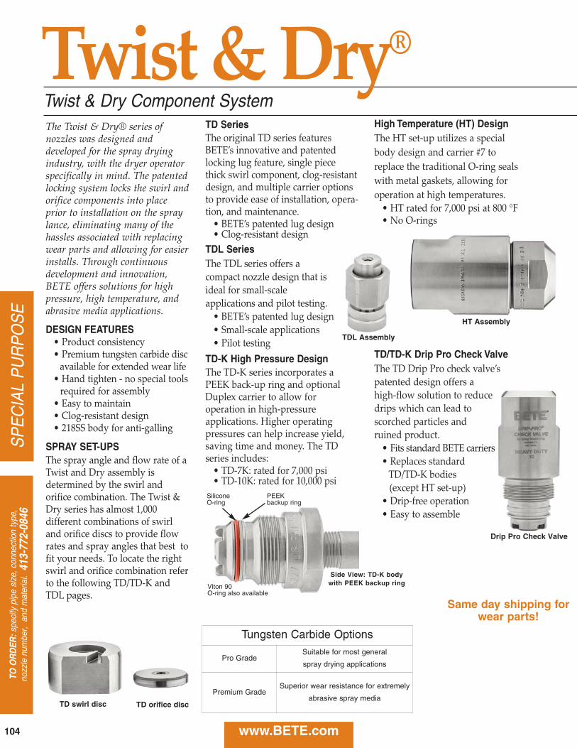
Twist & Dry Component SystemThe Twist & Dry® series ofnozzles was designed anddeveloped for the spray dryingindustry, with the dryer operatorspecifically in mind. The patentedlocking system locks the swirl andorifice components into placeprior to installation on the spraylance, eliminating many of thehassles associated with replacingwear parts and allowing for easierinstalls. Through continuousdevelopment and innovation,BETE offers solutions for highpressure, high temperature, andabrasive media applications.
DESIGN FEATURES• Product consistency• Premium tungsten carbide disc
available for extended wear life• Hand tighten no special tools
required for assembly• Easy to maintain• Clogresistant design• 218SS body for antigalling
SPRAY SET-UPSThe spray angle and flow rate of aTwist and Dry assembly isdetermined by the swirl andorifice combination. The Twist &Dry series has almost 1,000different combinations of swirland orifice discs to provide flowrates and spray angles that best tofit your needs. To locate the rightswirl and orifice combination referto the following TD/TDK andTDL pages.
TD SeriesThe original TD series featuresBETE’s innovative and patentedlocking lug feature, single piecethick swirl component, clogresistantdesign, and multiple carrier optionsto provide ease of installation, operation, and maintenance.
• BETE’s patented lug design • Clogresistant design
TDL SeriesThe TDL series offers acompact nozzle design that isideal for smallscaleapplications and pilot testing.
• BETE’s patented lug design• Smallscale applications • Pilot testing
TD-K High Pressure DesignThe TDK series incorporates aPEEK backup ring and optionalDuplex carrier to allow foroperation in highpressureapplications. Higher operatingpressures can help increase yield,saving time and money. The TDseries includes:
• TD7K: rated for 7,000 psi • TD10K: rated for 10,000 psi
High Temperature (HT) DesignThe HT setup utilizes a specialbody design and carrier #7 toreplace the traditional Oring sealswith metal gaskets, allowing foroperation at high temperatures.
• HT rated for 7,000 psi at 800 °F• No Orings
TD/TD-K Drip Pro Check ValveThe TD Drip Pro check valve’spatented design offers ahighflow solution to reducedrips which can lead toscorched particles andruined product.
• Fits standard BETE carriers• Replaces standard
TD/TDK bodies (except HT setup)
• Dripfree operation• Easy to assemble
Side View: TD-K bodywith PEEK backup ring
SiliconeO-ring
PEEKbackup ring
Viton 90 O-ring also available
TD swirl disc TD orifice disc
Twist & Dry®
Drip Pro Check Valve
HT Assembly
TDL Assembly
Same day shipping forwear parts!
Tungsten Carbide Options
Pro GradeSuitable for most general
spray drying applications
Premium GradeSuperior wear resistance for extremely
abrasive spray media

CA
LL 413-772-0846C
all for the name of your nearest B
ET
E representative.
105
SP
EC
IAL P
UR
PO
SE
www.BETE.com
Twist & Dry® Components & Options
¼ TD 2 - 025 - CI1 - 7K – 45 – B
pipe size
series
swirl number
orifice
carrier style
pressureomit for TD/TDL or if using HT set-up (HT body and carrier #7)
7K7K see Material Selection Guide includes PEEK backup ring
10K10K includes PEEK backup ring and Duplex 2205 carrier material
omit for standard carrier (model #2) or if using HT set-up (HT body and carrier #7)
connection typeomit if NPT or Butt WeldB if BSP
temperatureomit if temperature is less than or equal to 400 °F (204 °C)
4545 if temperature is greater than 400 °F (204 °C) and less than or equal to 450 °F (232 °C); includes Silicone O-ring and PTFE CV seal if applicable
– CVB
check valveomit if no check valve is neededor using HT body
HTHT if temperature is greater than 450 °F (232 °C) and less than or equal to 800 °F (427 °C); max pressure 7000 psi (485 bar)
CVBCVB for 30 psi (2 bar) cracking pressure CVCCVC for 75 psi (5 bar) cracking pressure
add xx-BWxx-BW if Butt Weld(include pipe schedule where xx)
see Material Selection Guide
To Order: Spray Set-up Number
Carrier 1 (CI1) (shown)
Carrier 11 (CI11) - without lug
Carrier 2 (CI2) (shown)
Carrier 5 (CI5) - without lug
Carrier 10 (CI10) (shown)
Carrier 12 (CI12) - without lug
Twist & Dry Material Selection Guide
Pressure Temperature
psi bar up to 302 °F (150 °C) up to 400 °F (204 °C) up to 450 °F (232 °C) up to 800 °F (427 °C)
10,000 690
10K Set-up
Viton O-ring w/ PEEK
Backup Ring
Carrier in Duplex 2205
10K Set-up
Viton O-ring w/ PEEK
Backup Ring
Carrier in Duplex 2205
10K Set-up
Silicone O-ring w/ PEEK
Backup Ring
Carrier in Duplex 2205
7,000 485
7K Set-up
Viton O-ring w/ PEEK
Backup Ring
7K Set-up
Viton O-ring w/ PEEK
Backup Ring
7K Set-up
Silicone O-ring w/ PEEK
Backup Ring
HT Set-up
Metal Gaskets
High Temperature Body
Carrier #75,000 345 TD/TDL Set-up
Viton O-ring3,500 240 TD/TDL Set-up
Viton O-ring800 55
TD/TDL Set-upSilicone O-ring
Durable Beard-Deterring Standard Carrier Knife Edge Anti-Bearding
Talk to one of our engineers; we’re here to help you find the right solution for your application!
413-772-0846

106
SP
EC
IAL
PU
RP
OS
ETO
OR
DER
:spe
cify
pip
e si
ze, c
onne
ctio
n ty
pe,
nozz
le n
umbe
r, a
nd m
ater
ial.
413
-772
-084
6
www.BETE.com
TD/TDKTwist & Dry® Hollow Cone
DESIGN FEATURES• Patented locking mechanism for quick and
easy change-out and maintenanceHigh pressure applications:
• TD-K with PEEK backup ring• HT body with Carrier #7
High temperature applications:• TD/TD-K bodies with silicone O-ring• HT body with Carrier #7
• Female pipe thread or butt-weld connections• Hand tighten, no special tools required• Orifice size: 0.034” through 0.157”• Interchangeable swirl and orifice discs for
variable patterns and flow rates
• Drip Pro check valve available upon request
• Multiple grades of tungsten carbide to suit application needs
• Same day shipping of wear parts• Clog-resistant design• Easy to maintainSPRAY CHARACTERISTICSSpray pattern: Hollow ConeFlow rates: 8.94 to 2,210 gphSpray angle: 50° through 85°, as listed
Cutaway view of carrier showingBETE’s uniquelocking lug feature
70° Hollow Cone
TD Assembly
GALLONS PER HOUR @ PSIFemalePipe Nozzle Spray Dia. K 200 500 750 1000 1250 1500 1750 2000 2500 3000 4000 7000 Size Number Angle Swirl (in.) Factor PSI PSI PSI PSI PSI PSI PSI PSI PSI PSI PSI PSI
TD2-34 70° SW2 0.034TD1-37 80° SW1 0.037 0.632 8.94 14.1 17.3 20.0 22.4 24.5 26.5 28.3 31.6 34.6 40.0 52.9
TD2-40 75° SW2 0.040TD1-49 85° SW1 0.049 0.791 11.2 17.7 21.7 25.0 28.0 30.6 33.1 35.4 39.5 43.3 50.0 66.2
1/4” 60° SW4 0.034
OR
TD3-40 70° SW3 0.040 0.949 13.4 21.2 26.0 30.0 33.5 36.7 39.7 42.4 47.4 52.0 60.0 79.4
3/8”
TD5-34 50° SW5 0.034
OR
TD4-40 65° SW4 0.040 1.11 15.7 24.7 30.3 35.0 39.1 42.9 46.3 49.5 55.3 60.6 70.0 92.9
1/2”
TD4-43 65° SW4 0.043
OR
TD3-49 75° SW3 0.049 1.26 17.9 28.3 34.6 40.0 44.7 49.0 52.9 56.6 63.2 69.3 80.0 105
3/4”
TD6-37 50° SW6 0.037TD5-40 60° SW5 0.040 1.42 20.1 31.8 39.0 45.0 50.3 55.1 59.5 63.6 71.2 77.9 90.0 119TD4-46 70° SW4 0.046TD3-55 75° SW3 0.055
TD6-40 50° SW6 0.040TD5-43 60° SW5 0.043 1.58 22.4 35.4 43.3 50.0 55.9 61.2 66.1 70.7 79.1 86.6 100 132TD4-52 70° SW4 0.052
TD5-49 60° SW5 0.049TD4-58 70° SW4 0.058 1.74 24.6 38.9 47.6 55.0 61.5 67.4 72.8 77.8 87.0 95.3 110 146TD3-67 80° SW3 0.067
TD4-34
Use TD-K for operation over 3,500 psi
Flow Rate (GPH ) = K
Orifice
√PSIPSI
10,000 PSI
63.2
79.1
94.9
111
126
142
158
174
Twist & Dry/TD-K Flow RatesHollow Cone; 50°- 85° Spray Angles; 1/4”, 3/8”, 1/2”, and 3/4” Pipe Sizes; NPT, BSP, or Weld Prep
Dimensions are approximate. Check with BETE for critical dimension applications.
Pipe SizeWeight*
(oz.)
1/4” 19
3/8” 18.5
1/2” 18
3/4” 17
1-3/8
*
*
Spray angle performance varies with pressure. Contact BETE for specific data on critical applications.
*Applies to threaded TD body and standard carrier(s)
Standard Materials: Carrier: Stainless Steel, Duplex; Body: Stainless Steel; Swirl/Orifice: Tungsten Carbide

CA
LL 413-772-0846C
all for the name of your nearest B
ET
E representative.
107
SP
EC
IAL P
UR
PO
SE
www.BETE.com
Twist & Dry/TD-K Flow RatesHollow Cone; 50° - 85° Spray Angles; 1/4”, 3/8”, 1/2”, and 3/4” Pipe Sizes; NPT, BSP, or Weld Prep
GALLONS PER HOUR @ PSI Female Pipe Nozzle Spray Dia. K 200 500 750 1000 1250 1500 1750 2000 2500 3000 4000 7000Size Number Angle Swirl (in.) Factor PSI PSI PSI PSI PSI PSI PSI PSI PSI PSI PSI PSI
TD6-46 55° SW6 0.046TD5-52 65° SW5 0.052 1.90 26.8 42.4 52.0 60.0 67.1 73.5 79.4 84.9 94.9 104 120 159TD4-61 75° SW4 0.061TD3-70 80° SW3 0.070
TD6-52 55° SW6 0.052TD5-58 65° SW5 0.058 2.21 31.3 49.5 60.6 70.0 78.3 85.7 92.6 99.0 111 121 140 185TD4-70 75° SW4 0.070
TD7-49 50° SW7 0.049TD6-55 60° SW6 0.055TD5-64 70° SW5 0.064
2.53 35.8 56.6 69.3 80.0 89.4 98.0 106 113 126 139 160 212
TD4-76 80° SW4 0.076
TD7-52 50° SW7 0.052TD6-61 60° SW6 0.061 2.85 40.2 63.6 77.9 90.0 101 110 119 127 142 156 180 238
TD5-70 70° SW5 0.070
TD7-58 55° SW7 0.058TD6-64 65° SW6 0.064 3.16 44.7 70.7 86.6 100 112 122 132 141 158 173 200 264TD5-76 75° SW5 0.076TD4-91 80° SW4 0.091
TD7-61 55° SW7 0.061TD6-70 65° SW6 0.070 3.48 49.2 77.8 95.3 110 123 135 146 156 174 191 220 291
TD5-82 75° SW5 0.082
TD7-64 55° SW7 0.064TD6-76 65° SW6 0.076 3.79 53.7 84.9 104 120 134 147 159 170 190 208 240 317
TD5-88 75° SW5 0.088
TD8-67 50° SW8 0.067TD7-76 60° SW7 0.076TD6-88 70° SW6 0.088
4.74 67.1 106 130 150 168 184 198 212 237 260 300 397
TD5-109 80° SW5 0.109
TD8-76 50° SW8 0.076TD7-85 65° SW7 0.085 5.69 80.5 127 156 180 201 221 238 255 285 312 360 476
TD6-103 75° SW6 0.103
TD8-82 55° SW8 0.082TD7-97 65° SW7 0.097 6.64 93.9 148 182 210 235 257 278 297 332 364 420 556
TD6-115 75° SW6 0.115
TD9-82 50° SW9 0.082TD8-91 60° SW8 0.091TD7-106 70° SW7 0.106
7.59 107 170 208 240 268 294 317 339 379 416 480 635
TD6-127 80° SW6 0.127
TD9-88 50° SW9 0.088TD8-100 60° SW8 0.100TD7-118 70° SW7 0.118
8.54 121 191 234 270 302 331 357 382 427 468 540 715
TD6-142 80° SW6 0.142
TD9-94 55° SW9 0.094TD8-106 65° SW8 0.106 9.49 134 212 260 300 335 367 397 424 474 520 600 794
TD7-127 75° SW7 0.127
TD9-106 55° SW9 0.106TD8-121 65° SW8 0.121 11.1 157 247 303 350 391 429 463 495 553 606 700 929
TD7-145 75° SW7 0.145
TD10-103 50° SW10** 0.103TD9-115 60° SW9 0.115 12.7 179 283 346 400 447 490 529 566 632 693 800 1063
TD8-133 70° SW8 0.133
TD10-118 55° SW10** 0.118TD9-127 60° SW9 0.127 14.2 201 318 390 450 503 551 595 636 712 779 900 1188
TD8-145 70° SW8 0.145
TD9-136 65° SW9 0.136TD8-157 75° SW8 0.157
15.8 224 354 433 500 559 612 661 707 791 866 1000 1322
TD9-148 65° SW9 0.148 17.4 246 389 476 550 615 674 728 778 870 953 1100 1456
TD10-136 60° SW10** 0.136TD9-154 70° SW9 0.154
19.0 268 424 520 600 671 735 794 849 949 1040 1200 1590
TD10-151 60° SW10** 0.151 20.6 291 460 563 650 727 796 860 919 1030 1130 1300 1724
TD10-157 65° SW10** 0.157 22.1 313 495 606 700 783 857 926 990 1110 1210 1400 1849
�
Use TD-K for operation over 3,500 psi
Flow Rate (GPH ) = K
Orifice
√PSIPSI
10,000PSI
190
221
253
285
316
348
379
474
569
664
759
854
949
1110
1270
1420
1580
1740
1900
2060
2210
1/4”
OR
3/8”
OR
1/2”
OR
3/4”
Spray angle performance varies with pressure. Contact BETE for specific data on critical applications.
Standard Materials: Carrier: Stainless Steel, Duplex; Body: Stainless Steel; Swirl/Orifice: Tungsten Carbide
**SW10 only available in Pro Grade Tungsten Carbide

108
SP
EC
IAL
PU
RP
OS
ETO
OR
DER
:spe
cify
pip
e si
ze, c
onne
ctio
n ty
pe,
nozz
le n
umbe
r, a
nd m
ater
ial.
413
-772
-084
6
www.BETE.com
TDLTwist & Dry® Low Flow Hollow ConeDESIGN FEATURES• Patented locking mechanism for quick
and easy change-out and maintenance• Lower flow rates than Twist & Dry
seriesFemale-threaded or butt weld
pipe connections• Orifice size: 0.018” through 0.058”• Interchangeable swirl and orifice discs
for variable patterns and flow rates
SPRAY CHARACTERISTICS• Hollow ConeFlow rates: 2.86 to 123 gphSpray angle: 70° - 75°
Ideal for small-scale applications and pilot tests
TDL Assembly
70° Hollow Cone
1 1/4”
GALLONS PER HOUR @ PSIFemalePipe Nozzle
OrificeDia. K 200 500 750 1000 1250 1500 1750 2000 2500 3000 4000 5000
Size Number Swirl (in.) Factor PSI PSI PSI PSI PSI PSI PSI PSI PSI PSI PSI PSITDL4-18 SWL4 0.018 0.202 2.86 4.53 5.54 6.40 7.16 7.84 8.47 9.1 10.1 11.1 12.8 14.3TDL4-20 SWL4 0.020 0.215 3.04 4.81 5.89 6.80 7.60 8.33 9.00 9.62 10.8 11.8 13.6 15.2TDL4-22 SWL4 0.022 0.237 3.35 5.30 6.50 7.50 8.39 9.19 9.92 10.6 11.9 13.0 15.0 16.8TDL4-24 SWL4 0.024 0.272 3.85 6.08 7.45 8.60 9.62 10.5 11.4 12.2 13.6 14.9 17.2 19.2
1/4” SWL4 0.027 0.316 4.47 7.07 8.66 10.0 11.2 12.2 13.2 14.1 15.8 17.3 20.0 22.4
TDL1-22 SWL1 0.022 0.348 4.92 7.78 9.53 11.0 12.3 13.5 14.6 15.6 17.4 19.1 22.0 24.6TDL1-24 SWL1 0.024 0.395 5.59 8.84 10.8 12.5 14.0 15.3 16.5 17.7 19.8 21.7 25.0 28.0
OR
TDL1-27 SWL1 0.027 0.459 6.48 10.3 12.6 14.5 16.2 17.8 19.2 20.5 22.9 25.1 29.0 32.4TDL1-30 SWL1 0.030 0.522 7.38 11.7 14.3 16.5 18.4 20.2 21.8 23.3 26.1 28.6 33.0 36.9
TDL2-30 SWL2 0.030 0.632 8.94 14.1 17.3 20.0 22.4 24.5 26.5 28.3 31.6 34.6 40.0 44.7
3/8”
TDL2-33 SWL2 0.033 0.712 10.1 15.9 19.5 22.5 25.2 27.6 29.8 31.8 35.6 39.0 45.0 50.3TDL2-36 SWL2 0.036 0.791 11.2 17.7 21.7 25.0 28.0 30.6 33.1 35.4 39.5 43.3 50.0 55.9TDL2-38 SWL2 0.038 0.838 11.9 18.7 22.9 26.5 29.6 32.5 35.1 37.5 41.9 45.9 53.0 59.3TDL2-40 SWL2 0.040 0.917 13.0 20.5 25.1 29.0 32.4 35.5 38.4 41.0 45.9 50.2 58.0 64.8TDL2-42 SWL2 0.042 0.949 13.4 21.2 26.0 30.0 33.5 36.7 39.7 42.4 47.4 52.0 60.0 67.1
TDL4-27
TDL2-44 SWL2 0.044 0.980 13.9 21.9 26.8 31.0 34.7 38.0 41.0 43.8 49.0 53.7 62.0 69.3TDL2-46 SWL2 0.046 1.03 14.5 23.0 28.1 32.5 36.3 39.8 43.0 46.0 51.4 56.3 65.0 72.7TDL2-48 SWL2 0.048 1.11 15.7 24.7 30.3 35.0 39.1 42.9 46.3 49.5 55.3 60.6 70.0 78.3TDL2-50 SWL2 0.050 1.15 16.3 25.8 31.6 36.5 40.8 44.7 48.3 51.6 57.7 63.2 73.0 81.6TDL2-52 SWL2 0.052 1.25 17.7 27.9 34.2 39.5 44.2 48.4 52.3 55.9 62.5 68.4 79.0 88.3TDL2-54 SWL2 0.054 1.30 18.3 29.0 35.5 41.0 45.8 50.2 54.2 58.0 64.8 71.0 82.0 91.7TDL2-56 SWL2 0.056 1.33 18.8 29.7 36.4 42.0 47.0 51.4 55.6 59.4 66.4 72.7 84.0 93.9
TDL3-50 SWL3 0.050 1.42 20.0 31.7 38.8 44.8 50.1 54.9 59.3 63.4 70.8 77.6 89.6 100TDL3-52 SWL3 0.052 1.51 21.4 33.8 41.4 47.8 53.4 58.5 63.2 67.6 75.6 82.8 95.6 107TDL3-54 SWL3 0.054 1.60 22.6 35.7 43.7 50.5 56.5 61.8 66.8 71.4 79.8 87.5 101 113TDL3-56 SWL3 0.056 1.69 23.9 37.8 46.3 53.5 59.8 65.5 70.8 75.7 84.6 92.7 107 120TDL3-58 SWL3 0.058 1.74 24.6 38.9 47.6 55.0 61.5 67.4 72.8 77.8 87.0 95.3 110 123
Flow Rate (GPH ) = K
TDL Flow Rates Hollow Cone, 70° - 75° Spray Angles, 1/4” and 3/8” Pipe Sizes, NPT or BSP
√PSIPSI
Dimensions are approximate. Check with BETE for critical dimension applications.
Spray angle performance varies with pressure. Contact BETE for specific data on critical applications.
Pipe SizeWeight
(oz)
1/4” 4.2
3/8” 3.8
Standard Materials: Carrier: Stainless Steel; Body: Stainless Steel; Swirl/Orifice: Tungsten Carbide
Body O-ring Swirl Orifice O-ring Carrier Carrier Nut

2. Place orifice disc into carrier.The polished radius side of thedisc should be facing you whenproperly positioned.
1. Place carrier o-ring into carrier 3. Place swirl chamber into carrier.Hold swirl chamber with screwdriverslot facing you. Align flat side of swirlwith lugs in carrier. Drop into carrier.
7. Although lubricating the large o-ring is not required, using theenclosed lubricant eases the lastassembly step.
8. Hand tighten (25 in-lb. torquemax.) the carrier to the body.(Even if the body is welded to alance, the carrier goes on easilyand the internal parts are held intheir proper position.)
9. Now thread assembled TD nozzleonto system piping.
4. The swirl chamber is now readyto be “locked” into the carrier.
The Easiest Assembly of Any Spray Drying Nozzle Available Today
carrier
carrier o-ring
swirl disk
swirl unit
body o-ring
body
5. Use flathead screwdriver, with aslight push the swirl chamber can betwisted to ‘lock’ beneath the lugs. Theswirl chamber and orifice disc are nowsecurely held in place for continued
Tech Tip!An easy way to line up the orifice discinside the carrier is to place it on thepoint of a plastic rod or pencil anduse the device to guide the disc intoposition. Then flip the carrier overand insert the swirl unit and twist.
assembly. Components remainproperly positioned regardless oforientation due to unique BETElocking system.6. Place o-ring on body in groove

BETE Fog Nozzle, Inc.PO Box 1438, 50 Greenfield StreetGreenfield, MA 01302-1438 USA
Telephone: 413-772-2166 • 413-772-0846FAX: 413-772-6729email: [email protected]
Contact Your Local Representative:


![[Titans Rising Series Vol. I] Scorched Earth](https://static.fdocuments.in/doc/165x107/577cc18b1a28aba711934c1c/titans-rising-series-vol-i-scorched-earth.jpg)
