
Nozzle Lances and Systems for Gas Cooling and Conditioning · 2018-09-25 · Our nozzle lances...
24
Nozzle Lances and Systems for Gas Cooling and Conditioning
Transcript of Nozzle Lances and Systems for Gas Cooling and Conditioning · 2018-09-25 · Our nozzle lances...

Nozzle Lances and Systems for Gas Cooling and Conditioning

2
Innovative solutions for a trending market
Lechler is your innovative and reliable partner in all matters relating to gas cooling and conditioning. Always with the aim of employing our expert knowledge to optimize your process.
Effi cient gas conditioning off ers a wide range of ap-proaches to reduce costs and increase effi ciency. A prerequisite is that the respective processes are thoroughly understood and that the gas conditioning is adapted accordingly.
EFFICIENT COOLING AND CONDITIONING WITH LECHLER NOZZLE LANCES AND SYSTEMS
The right solution for every requirement
With our wide range of nozzles and gas conditioning systems, we off er the perfect solution for every application. Every plant naturally comes with its own set of challenges.
Our nozzle lances and systems have proved in diff erent applications and plants all over the world:
�� Cement and lime industry�� Waste incineration plants�� Power plants�� Steel industry�� Glass industry�� Chemical industry
We rise to these challenges and work with you to de-velop the best solutions for your business. We support you with comprehensive consulting services ranging from process analysis to turnkey solutions.
18931879 19781962
Lechler is Europe’s No. 1 and is also one of the leading suppliers of nozzles and systems world-
wide. For over 135 years, we have pioneered numerous groundbreaking developments in the
fi eld of nozzle technology. We combine comprehensive nozzle engineering expertise with a deep
understanding of application-specifi c requirements to create products that off er outstanding
performance and reliability.
Company founded by Paul Lechler Patent for liquid atomization Expansion to the USA and then to other countries
Sales offi ces set up in Germany

3
For many years now, nozzles and spray systems for indus-trial gas conditioning have been an integral part of our Environmental Technologies portfolio. An international team of outstanding engi-neers and process engineers continuously develop new solutions and adapt them to new challenges.
Through the use of globaldatabases and closecooperation with external specialized institutes and re-nowned plant manufacturers, we have built up an interdi s-ciplinary knowledge base – and with it optimal process integration.
Our constant exchange of experiences with plant operators means we are always in tune with the latest developments and can reactproactively to them.
To provide you with local support, we are represented all around the globe – with locations in the USA, Great Britain, India, China, ASEAN, France, Belgium, Italy, Finland, Hungary, Spain and Sweden, as well as sales partners in almost every country.
COMPETENCE – THE ADVANTAGE OF MULTIPLE PERSPECTIVES
Costs under control
In most processes with hot off gases generally extreme environmental conditions prevail. We manufacture our nozzles from highly resistant materials with minimal wear.
The long service life of our high-quality components for valve skid units and systems does not just reduce the pure
costs of spare parts, but also decreases downtimes and maintenance costs. In addition, customer-specifi c systems lower the operating costs to a minimum.
Twin-fl uid nozzles allow for an application-optimized fi ne droplet spectrum, whereas spillback systems do away with compressed air alto-gether to reduce the energy consumption.
2016201019951988
Our job is to identify the appropriate solution in each case and then adapt it perfectly to the on-site conditions.
Wide product range
Service
Processoptimization
Process reliability
Costsavings
Experience
Custom made solutions
CUSTOMER ADVANTAGES
Environmental Technologies division founded
Production, sales and administration are concentrated in Metzingen
Expansion of production with new 13,000 m² production hall
Opening of the ultra-modern Development and Technology Center in Metzingen
44
LET’S OPTIMIZE YOUR GAS COOLING PROCESS
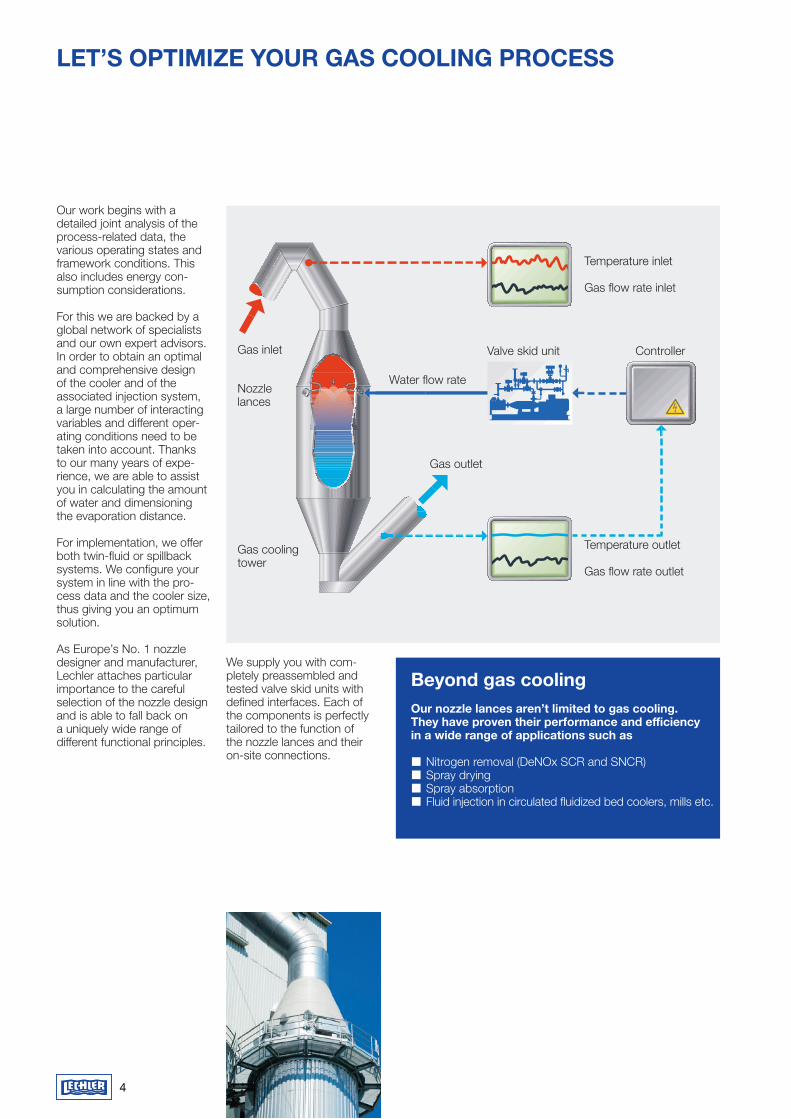
Our work begins with a detailed joint analysis of the process-related data, the various operating states and framework conditions. This also includes energy con-sumption considerations.
For this we are backed by a global network of specialists and our own expert advisors.In order to obtain an optimal and comprehensive design of the cooler and of the associated injection system, a large number of interacting variables and different oper-ating conditions need to be taken into account. Thanks to our many years of expe-rience, we are able to assist you in calculating the amount of water and dimensioning the evaporation distance.
For implementation, we offer both twin-fluid or spillback systems. We configure your system in line with the pro-cess data and the cooler size, thus giving you an optimum solution.
As Europe’s No. 1 nozzle designer and manufacturer, Lechler attaches particular importance to the careful selection of the nozzle design and is able to fall back on a uniquely wide range of different functional principles.
Beyond gas coolingOur nozzle lances aren’t limited to gas cooling. They have proven their performance and efficiency in a wide range of applications such as
� Nitrogen removal (DeNOx SCR and SNCR) � Spray drying � Spray absorption � Fluid injection in circulated fluidized bed coolers, mills etc.
Gas inlet
Gas outlet
Gas cooling tower
Nozzle lances
Water flow rate
Valve skid unit Controller
Temperature inlet
Gas flow rate inlet
Temperature outlet
Gas flow rate outlet
We supply you with com-pletely preassembled and tested valve skid units with defined interfaces. Each of the components is perfectly tailored to the function of the nozzle lances and their on-site connections.

Steel industry
Glass industry
Chemical industry
Power plants
Waste incineration plants
Cement and lime industry
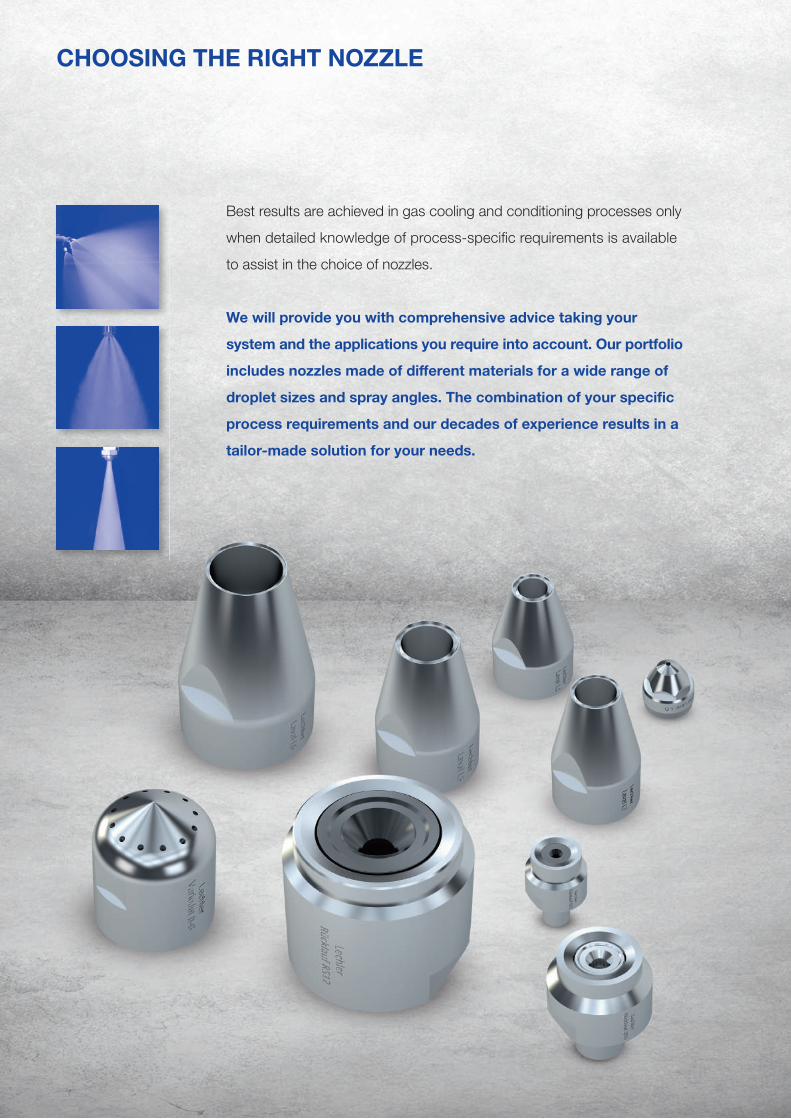
CHOOSING THE RIGHT NOZZLE
Best results are achieved in gas cooling and conditioning processes only
when detailed knowledge of process-specifi c requirements is available
to assist in the choice of nozzles.
We will provide you with comprehensive advice taking your
system and the applications you require into account. Our portfolio
includes nozzles made of diff erent materials for a wide range of
droplet sizes and spray angles. The combination of your specifi c
process requirements and our decades of experience results in a
tailor-made solution for your needs.

7
Spillback nozzlesAtomization without compressed air
Lechler spillback nozzles atomize liquids as a fi ne hollow cone.
This special single-fl uid nozzle works according to the pres-sure atomization principle. The water is sent to the noz-zle with a relatively constant feed pressure, independent of the atomized fl ow rate.
The amount of liquid injected is adjusted via a control valve in the spillback line, where-by part of the fl ow is taken from the inlet fl ow rate and returned to the tank. The maximum atomized fl ow rate is achieved with the control valve closed.
Uniform and fi ne liquid atomi-zation is achieved across the entire control range.
The atomized fl ow rate can be distributed over cluster heads with up to six small nozzles. This results in a total spray angle of approximately 120°.This wide distribution of liquid over the entire duct is ad-vantageous for reducing the number of lances.
Spray angle of the individual nozzles 90° or 60° as hollow cone
High turn-down ratio of up to 12:1
Use: � Gas cooling in medium-sized and large gas cooling towers
Properties
Constant feed pressurep1 = 35 bar, gFlow rate
Atomized liquid
Return pressure p2 [bar, g]
Flo
w r
ate
V [
l/m
in]
.
V3 min
V3 max
V3
V2
V1
V1: flow rate
Vpump: max. flow rate
V2: return flow
V3: atomized liquid
V3= V1 – V2
V3 min: min. atomized liquid (return line open)
V3 max: max. atomized liquid (return line closed)
p1: constant feed pressure
p2: return pressure
Turn down ratio: V3 max/V3 min
Vpump
.
.
.
.
.
.
.
.
.
.
.
. . .
.
. .
Low operating costs as no atomizing air required
Even and fi ne liquid atomization over the entire control range
Execution as single or cluster nozzle lances pos-sible
Typical pressure rangeof 35 bar, g in the supply line at the nozzle
Spray pattern of a single spillback nozzle
Spray pattern of a cluster spillback nozzle lance
V1
V2 bar
Supply with constant feed pressure
Spillback line
Hollow cone
Scheme of the spillback nozzle

8
Lechler VarioJet® nozzles atomize according to the principle of internal mixing. With this twin-fl uid nozzle, the water is fed in axially via a bore hole.
After arriving at the cone tip, the liquid is split up into a thin liquid fi lm. This thin liquid fi lm is split into fi nest droplets by the atomizing air in the mixing chamber. The resulting two-phase mixture is then atomized a second time when exiting via several bore holes arranged in a circular fashion.
Thanks to the innovative design of the nozzle, a spray with a large outlet angle is achieved. This is characte-rized by an even liquid distribution as well as a fi ne droplet spectrum with a low specifi c air consumption.
The fi neness of the droplet spectrum is decisively infl u-enced by the air/liquid ratio and by the pressure level of the two fl ow rates. As a gen-eral rule: the higher the air/liquid ratio and the higher the pressure level of atomizing air and liquid is, the fi ner the droplet spectrum.
The large free cross-sections in the nozzle keep the risk of clogging and the mainte-nance eff ort to a minimum.
Use: � Gas cooling in gas cooling towers as well as gas-bearing pipes (ducts)
Large spray angle (60°, 90°) forgood coverage of the cross-section of the duct
High turn-down ratio up to 20:1
Properties
Variable control concepts of twin-fl uid nozzles
Air
flo
w r
ate
[m³/
h S
TD
]
Water flow rate [l/min]
1 2AConstantatomizer air pressure
1 2BConstantatomizer air volume flow
1 2CConstantdroplet diameter
p(air)= 4 barp(air)= 3 barp(air)= 2 barp(air)= 1 bar
1
2A
2B
2C
p(air)= 5 barp(air)= 6 bar
d32=60μm
d32=80μm
d32=90μm
d32=100μm
d32=110μm
d32=120μm
d32=130μm
d32=140μm
d32=150μm
d32=160μm
d32=70μm
Adjustment of the droplet spectrum by changing the air/fl uid ratio
Low air consumption
Clog-resistant thanks to large free cross-sections without internal fi ttings
Typical pressure range Liquid 1–9 bar, gAtomizing air 1–6 bar, g
Spray pattern of the VarioJet® nozzle
Scheme of the VarioJet® nozzle
Atomizing air Liquid
Two-phase mixture
Secondary atomization
VarioJet® nozzlesTwin-fl uid nozzles with low air consumption despite large outlet angle
V1
V2 bar

9
Laval nozzlesTwin-fl uid nozzles for a wide droplet spectrum in special applications
Lechler Laval nozzles atomize liquids as a fi ne full cone. These twin-fl uid nozzles work according to the super-sonic principle.
A dual-phase mixture is cre-ated from atomizing air and liquid in the mixing chamber inside the nozzle. The shape of the nozzle causes this mixture to be accelerated to supersonic speed, resulting in an extremely fi ne atomization of the droplets.
By changing the air/liquid ratio, the droplet size and the droplet spectrum can be adapted within a wide range. The large free cross sections of the nozzle also allow atomization of viscous or solids-laden liquids.
Choosing the right material prevents wear even where abrasive media are present, and enables use at high temperatures.
Use: � Gas cooling in gas-bearing pipes (ducts) and medium-sized and small gas cooling towers
� Injection of solids-laden water
� Introduction of lime water in the desulfuri-sation process
� Injection of aqueous ammonia or urea solution for the DeNOx process (SNCR/SCR)
� Chemical process engineering (spray dryers etc.)
Spray pattern of the Laval nozzle
Scheme of the Laval nozzle
Small spray angle (15°), suitable for small cross-sections and horizontal ducts
Very large turn down ratio of 20:1 (in some cases up to 40:1)
Properties
Adjustment of the droplet spectrum by changing the air/fl uid ratio
Very fi ne droplet spectrum
Clog-resistant thanks to large free cross-sections without internal fi ttings
Typical pressure range Liquid 1–6 bar, gAtomizing air 1–6 bar, g
Operating point of a twin-fl uid nozzle
p(air)= 4 barp(air)= 3 barp(air)= 2 bar
p(air)= 1 bar
p(air)= 5 bar
p(air)= 6 bar
d32= 130µm d32= 150µmVWater
.
VAir
.
d32=50μm
d32=60μm
d32=70μm
d32=80μm
d32=90μm
d32=100μm
d32=110μm
d32=120μm
Air
flo
w r
ate
[m³/
h S
TD
]
Water flow rate [l/min]
p(air)= 4 barp(air)= 3 barp(air)= 2 bar
p(air)= 1 bar
p(air)= 5 bar
p(air)= 6 bar
d32= 130µm d32= 150µm
Wat
er p
ress
ure
[bar
, g]
Water flow rate [l/min]
p(air)= 1 bar
p(air)= 2 bar
p(air)= 3 bar
p(air)= 4 barp(air)= 5 bar
p(air)= 6 bar
VWater
.
pWater
LiquidAtomizing air
Two-phase mixture
Constriction acceler-ates mixture to super-sonic speed
V1
V2 bar

10
Lechler nozzle lances ensure optimal spray place-ment and alignment in flue gas ducts. The choice of nozzles and the conside-ration of local conditions and process-related matters means they can be individu-ally adapted to the respective requirements.
The nozzles themselves have a low-maintenance design and can be quickly cleaned or exchanged with minimal effort.
The robust, high-quality stainless steel construction ensures a high degree of functional reliability. Lances are available in a variety of material to suit specific pro-cess requirements.
Lechler nozzle lances are available with many options, including but not limited to:�� Protection tube to increase the service life in case of higher temperatures, high dust loads and aggressive gases, with barrier air as an option
�� Wedge flange, standard flange and special flange in accordance with customer requirements�� Guide rail to facilitate lance installation�� Shifting device to change the insertion lenght – with or without gastight sealing�� Expansion joint or stuffing box for expansion com-pensation at high tempera-tures�� Assembly connecting piece with flange connector for welding onto flue gas duct
�� Further special customiza-tions including wear pro-tection, insulation, water cooling or coating�� Pre-assembled accessory kits for process media connections (e.g. quick release couplings, shut-off ball valves, strainers)
Lechler nozzle lances are manufactured in line with ultramodern production processes and according to the state of the art.
Nozzle lancesHighest spraying accuracy in the flue gas duct
Connection options Accessories
Option 1: Quick release couplings
Option 2: Flange connector Option 3: Conical
screw connection
Spillback nozzles
Option 1: Single nozzleOption 2: Cluster head with 3
to 6 single nozzles

11
Material
Lances are manufactured from stainless steel (316/316L) as standard, but depending on requirements can also be made of chemical and high-temperature resis-tant materials.
VarioJet® nozzle
Option 1: Without protection tube and without protection cap
Option 2: With protection tube and with protection cap
Talk to us
Each gas cooling tower and flue gas duct is different. Which is why standard solutions do not always make sense. Speak with us and let us work together to find the best solution for your purposes.
Flange connections
Option 1: WedgeOption 2: Standard flange e.g. DIN, ANSI etc.Option 3: Special flange according to customer
specification
1 2 3
Accessories are available in galvanized steel or stainless steel and the hoses are available in rubber or stainless steel.
... !
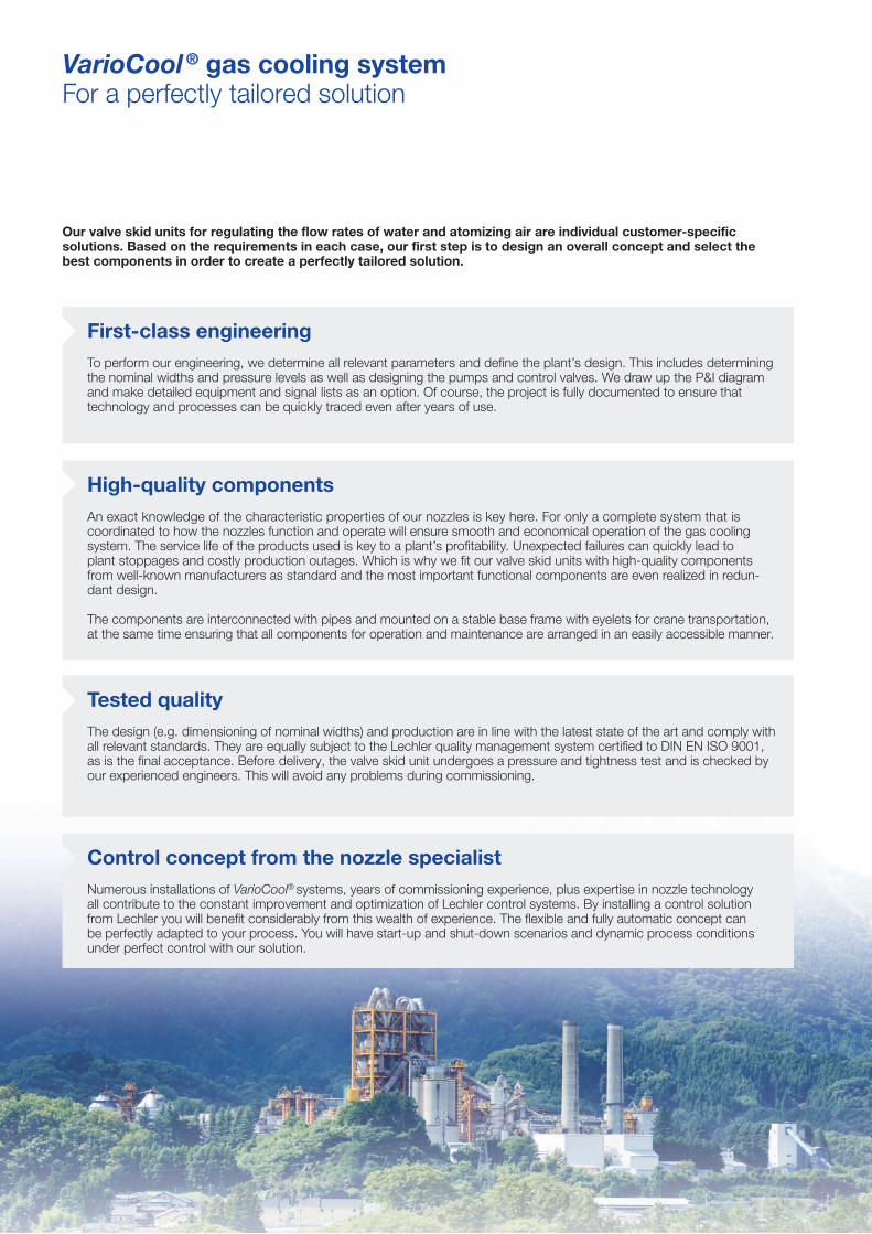
VarioCool ® gas cooling systemFor a perfectly tailored solution
Our valve skid units for regulating the fl ow rates of water and atomizing air are individual customer-specifi c solutions. Based on the requirements in each case, our fi rst step is to design an overall concept and select the best components in order to create a perfectly tailored solution.
First-class engineeringTo perform our engineering, we determine all relevant parameters and defi ne the plant’s design. This includes determining the nominal widths and pressure levels as well as designing the pumps and control valves. We draw up the P&I diagram and make detailed equipment and signal lists as an option. Of course, the project is fully documented to ensure that technology and processes can be quickly traced even after years of use.
High-quality componentsAn exact knowledge of the characteristic properties of our nozzles is key here. For only a complete system that is coordinated to how the nozzles function and operate will ensure smooth and economical operation of the gas cooling system. The service life of the products used is key to a plant’s profi tability. Unexpected failures can quickly lead to plant stoppages and costly production outages. Which is why we fi t our valve skid units with high-quality components from well-known manufacturers as standard and the most important functional components are even realized in redun-dant design.
The components are interconnected with pipes and mounted on a stable base frame with eyelets for crane transportation, at the same time ensuring that all components for operation and maintenance are arranged in an easily accessible manner.
Tested qualityThe design (e.g. dimensioning of nominal widths) and production are in line with the latest state of the art and comply with all relevant standards. They are equally subject to the Lechler quality management system certifi ed to DIN EN ISO 9001, as is the fi nal acceptance. Before delivery, the valve skid unit undergoes a pressure and tightness test and is checked by our experienced engineers. This will avoid any problems during commissioning.
Control concept from the nozzle specialistNumerous installations of VarioCool® systems, years of commissioning experience, plus expertise in nozzle techno logy all contribute to the constant improvement and optimization of Lechler control systems. By installing a control solution from Lechler you will benefi t considerably from this wealth of experience. The fl exible and fully automatic concept can be perfectly adapted to your process. You will have start-up and shut-down scenarios and dynamic process conditions under perfect control with our solution.

13
Option packages for our VarioCool® valve skid units
Electrical wiring of the components:
Junction box
All components except the pump motors are wired to a junction box
within the valve skid unit.
This assures that the customer has a central connection point for all
electrical components and measuring devices for further processing in the
higher-level control.
Control cabinet with complete PLC
All components including the pumps are wired to a control cabinet. The control cabinet is integrated into the base frame of the valve skid unit.
The complete injection control is tested in accordance with valid electrical standards and regulations and allows all relevant process parameters to be visualized over a control panel on the control cabinet. Specifi c confi guration and extensive testing make commissioning much faster. Communication and the exchange of signals (setpoint, plant status, error messages) with the customer’s logic system is carried out via PROFIBUS or PROFINET.
The control has several modes of operation such as automatic mode and manual mode for tests during plant downtimes. In the event of faults, our engineers can quickly perform a remote diagnosis via the installed modem without the need for an on-site visit.

14
VarioCool ® gas cooling systemFor a perfectly tailored solution
Ring mains
Ring mains are usually used to supply the lances. Lechler supplies ring mains and headers together with the corresponding brackets for welding onto the fl ue gas duct. Accessories such as pressure transmitters and manometers plus the appropriate connections for the lances and supply lines are also included in the scope of delivery.
Purge air connection
In order to increase the injection turn-down ratio, individual lances or lance groups can be connected or disconnected. If the disconnected lances are in the fl ue gas duct, the rest of the fl uid should be purged. Vaporization and deposits in the lance can be prevented in this way.
Extended scope of delivery

15
Water tank
A water tank made of steel or plastic serves as a reservoir for the valve skid unit and guarantees injection operation for a certain period of time in the event of the water supply failing. Its size is adapted to the injection quantity. The components for tank fi lling and level monitoring are included in the scope of delivery.
Temperature measurement
For a constantly regulated outlet temperature, it is very important for the response characteristics of the tem-perature sensors to be adapted to the ambient conditions. Lechler provides the appropriate thermometers and assists you in defi ning the installation position.
Barrier air fan
In order to protect the nozzles and lances from dust deposits and/or high temperatures, barrier air is frequently applied to them.
For this purpose, Lechler supplies fans geared to the specifi c application with various optional attachments such as a throttle valve, suction fi lter and silencer.
Talk to us
Do you require an option that is not listed? Or are you having planning issues? No problem. Tell us what your requirements are. We will fi nd the appropriate solution and ensure a seamless integration.
... !

16
ENGINEERING AND SERVICE
Our experience for your success
With our experienced engineering team, you have a competent contact for your project at all times – from technical design and detail engineering to commissioning and the replacement of spare and wearing parts. You will benefi t from direct contact and fewer communication channels to enable smooth completion of your project.
From digital to real
Each individual design of gas cooling and conditioning systems is based on innovative software. CFD calcula-tions are used for fl ow optimization. Using a 3D tool, we identify the optimum liquid distribution in the duct together with the necessary lance arrangement.
Our drawings are created using state-of-the-art design engineering software.
Exclusive solutions
Lechler off ers a system solution tailored to your application and plant-specifi c conditions. We use only high-quality components from renowned manufacturers for our valve skid units. If you choose a system with a control, you will get a complete solution for your gas cooling and conditioning requirement from a single source.
Future-proof
Lechler systems are built to withstand harsh conditions and enable reliable and long-term operation. But we too have to lend to the extreme process conditions. Which is why it is all the more important to us to have a guaranteed long-term supply of spare parts for wearing parts – worldwide. With our global network of repre-sentatives, we off er a worldwide platform for contact and advice. You will fi nd your competent contacts on the Lechler website.
Reliable service is part of our agreement
Lechler is Europe's No. 1 nozzle manufacturer. A key factor for this success is our service. For even after your system has been delivered, you are in good hands with Lechler. We off er a worldwide commissioning service provided by employees with many years of experience. A signal and performance test ensures optimal system operation taking all operating and safety aspects into consideration. An important point of commissioning is also the detailed briefi ng of operating and maintenance personnel in the operation and maintenance of the plant.
We are your competent partner who will provide you with assistance to solve your problems. Our on-site service for preventive maintenance ensures continuous operation. We will be more than happy to draw up a maintenance contract tailored to your needs.
Extensive documentation
Our nozzle lances and systems are designed and manufactured in line with the current standards and regulations. New plants are always delivered with project-related documentation containing all relevant information for commissioning, operation and mainte-nance. Lechler will also provide a verbal description of the function and control concept where desired.


�� Calculation of the fl ow fi eld including pressure losses with one or more fl owing media in pipes and fi ttings
�� Spray propagation including heat and mass transfer with the surrounding gases under practically all conceivable ambient conditions
�� Calculation of internal nozzle fl ows and prediction of the spray pattern, water dis-tribution and spray characteristics down to droplet sizes in the near-nozzle range
Our services:
�� Maximum effi ciency as regards: – the use of expensive consumable media – geometric dimensions of the overall spray
process
�� Through targeted optimization of: – nozzle selection– nozzle operating point (taking into account
your pumps, compressors and blowers)– liquid distribution– droplet sizes– infl ow and outfl ow of your process gases
in relation to the spray process (with the aim of achieving uniformity and reducing pressure losses)
Your advantages:
18
For us, perfection is not just a promise, but is based on calculation of computational Fluid Dynamics (CFD).
No matter what the spray application, the goal is always to achieve the maximum eff ect with the minimum possible use of material, spray media and energy. It is therefore essential to have a detailed understanding of how spray mist is formed and propagated. This is made possible by computer-aided simulation of the fl ow processes (CFD – Computational Fluid Dynamics) of one or more substances in static or dynamic environments taking into account heat and mass transfer.
These simulations incorporate our many decades of know-how from the fi eld of nozzle development. Initially, CFD was only an internal tool which helped us to develop a desired nozzle more quickly and precisely. The completion of our high-performance cluster with a processing power of around 8,500 GFlops means that we can now off er our know-how as a service. We simulate nozzle applications and processes individually for your environment and your requirements. So that your processes also run per-fectly in real life.
CFD ANALYSIS
Fluid Dynamics simulation as a process optimization tool

19
Benefits:�� Efficient cooler operation thanks to lower atomizing air consumption and/or lower connection pressu-res at the nozzle lances
Benefits:�� Optimal atomization effect�� Efficient use of the connected atomization media
Benefits:�� Reactive ammonia vapor is present where the gas containing nitrogen (NOx) flows
�� Wet ground avoided as well as possible caking on the inner wall of the cooler�� Stable process in various load cases
�� Reduction of the required nozzle connection pressures�� Individual nozzle development in the shortest time
�� Avoidance of unneces-sary NH3 slip, meaning efficient use of the ammonia solution�� Best possible reduction rates of nitrogen oxides
Optimization of the gas flow in the gas cooling tower
You can’t just guess at perfection, it must be precisely calculated
The flow behavior of gases is significantly determined by the geometry of the environment. By applying computer simulation using computational fluid dynamics (CFD), our specialists can detect unequal gas distributions as well as turbulence. Depending on the specific conditions, these issues can be resolved in different ways. Installing baffles, perforated plates or even repositioning nozzles can be simulated to achieve the desired flow chara cteristics. The result of optimized gas flow via CFD can significantly reduce energy and/or material requirements.
Design and continuous optimization of our products
Optimization of SNCR process – best possible selection and placement of nozzles
Before
After


21
MEASURING TECHNOLOGYHOW OUR RESOURCES HELP US ACHIEVE PRECISION
What we are doing before we do it
At Lechler, exact measure-ments have long been the basis for clearly defined spray characteristics. The data obtained in our laboratories form the foundation for any development and make it easier for our customers to choose nozzles for specific applications. This saves time, lowers costs and provides planning security.
Advanced technology
We have further expanded our research capacities by opening our own Develop-ment and Technology Center. A highlight here is a laser- assisted phase doppler ane-mometer. As one of the most modern optical measuring procedures, it measures the velocity and the diameter of spherical droplets simulta-neously and without contact. Using the data obtained, spectra can be reliably derived for particle size distributions and velo cities.
Measurements range from tiny water droplets in the micro meter region to very large droplets of around 8 millimeters. These are per-formed with a high temporal and spatial resolution.
Individual positions in the spray can be automati cally approached and measured with extremely high accuracy – in x, y and z directions.
Our unique selling point: Practice-based knowledge Since it was founded, Lechler has stood out for its development of new technologies. In more than a century we have suc-cessfully filed a large number of patents. Starting with the “Centrifugal Sprayer” from 1893 and going up to state-of-the-art technol ogies of the 21st Century. We will continue this proud tradition into the future, and our new technical center will be key to doing so. After seven years of construction, the Lechler Development and Technology Center was opened in the summer of 2016. Since then it has offered everything nozzle developers dream of on a surface of over 600 m². In addition to extensive measuring facilities, state-of-the-art test benches with a wide range of pump performances are available to measure and investigate sprays, from microfine mist to fuller sprays with varying jetting characteristics.
International cooperation
We at Lechler value the importance of international cooperation. For this is often what opens up new perspecti-ves on a problem. In addition, cooperation offers us the possibility of testing nozzles in very special test environments and of discovering new use scenarios in this way.

22
QUALITY WITH A SYSTEM
Lechler products are used in a wide variety of sectors and applications.
Which is why the products’ requirements are often very speci-fic to certain applications. We define the term “quality” as the extent to which our products fulfill our customers’ individual requirements.
We are certified according to internationally recognized standards. Conscientious working and constant quality controls have always been carried out at Lechler, from materials receiving, development and production right through to shipping. So that our products keep what we promise in their daily use.
Key figures of our ex-perimental cooler with industry partners:�� Approx. two megawatts of thermal performance�� Use of single-fluid and twin-fluid nozzles under the most realistic condi-tions possible�� Flexible variation of inlet and outlet temperatures
�� Monitoring of droplet sizes and numbers in several levels�� Detection of the evapo- ration rates of injected sprays�� Use of more than 50 sensors of different kinds for the precise detection of all operating parameters
Measurement validation of our calculation models taking the example of a gas cooling towerOur measurement range:
� Precise and reproducible measurement of droplet sizes and speeds in sprays
� Measurement of complete sprays or of local positions in a spray
� Documentation of the spectra for particle size distribution and velocities
� Determination of the Sauter mean diameter and of many other variables relevant for process engineering
� Measurement of very dense sprays using state-of- the-art laser technology
� Measurement of tiniest droplets in the µm region and measurement of very large drops of up to 8 mm
� Measurement of droplet velocities up to 200 m/s � High temporal and spatial resolution � Positions in the spray can be automatically approached and measured with extremely high accuracy – in a 3-dimensional space in x, y and z directions
� Very large measuring range allows measurement of very wide particle spectra
� The size and velocity of each individual droplet is detected
� Error-free results in accordance with ISO 9001 � Spray characteristics over area mapped in 3D � Detection of positive and negative velocity components
MEASURING TECHNOLOGY THE LECHLER DEVELOPMENT AND TECHNOLOGY CENTER
Talk to us
Your requirements are the first step towards a solution.We are more than happy to help you solve your individual tasks. Tell us your objectives and we will take care of the solution. If the solution is not yet available, we will tailor-make one for you. That is our promise.
... !

Dear customer,
to comment on your gas conditioning problem, we would require all data known to you and indispensable for computing.
Company:
Address:
Date:
Contact person:
Phone/Fax:
E-Mail:
1. Gas data�� Clinker production (in case of cement plant) t/d
�� Other components of gas (HCI, HF, CaCl2 etc.) [mg/Nm3*, humid]
�� Dust content in gas
�� System pressure (in the reaction area)
�� Altitude of the plant meters above sea level
2. Conditions on Site
�� Are gas cooling tower dimensions fi xed? Yes Ø [mm] dimensions [mm x mm](Please attach Sketch/drawing of GCT or Duct!) No Favorite -Ø [mm] dimensions [mm x mm]
�� Available reaction distance m Reaction distance to be determined
�� Direction of gas ⇓ ⇑ ⇒
�� Nozzle type: Single fl uid Twinfl uid Both types possible
�� Complete evaporation required? Yes No
�� Is water injection system always in operation? Yes No In case the operation is interrupted, running time %
Gas fl ow t inlet [°C] t outlet [°C] max.: min.: max.:
nominal: min.: max.: standard: max.:
min.: min.: max.:
Gas composition [Vol. %]H2O CO2 O2 N2
* T0 = 273 K (0°C), P0 = 1 bar
Data collection sheet for calculating a gas cooling system
Lechler GmbH · Precision Nozzles · Droplet SeparatorsP. O. Box 1323 · 72544 Metzingen, Germany · Phone +49 7123 962-0 · Fax +49 7123 962-405 · [email protected] · www.lechler.com
23
FOR YOUR QUESTIONS
FULL INFORMATION IS JUST A CLICK AWAY: THE LECHLER WEBSITE
Our website contains further information on our products as well as useful resources.
www.lechler.com
Nobody knows your process and requirements better than you. Your knowledge is critical to us in order to fi nd the optimal nozzle for your application.
Data collection sheet for design of a DeNOx system
Data collection sheet for design of a gas cooling system
www.lechler.de/environmental/questionnaire_gascooling
www.lechler.de/environmental/questionnaire_denox
Simply send us the com-pleted questionnaire or enter your information online.
QUESTIONNAIRE
World HeadquartersLechler CompaniesSales Offices
Ed
itio
n 09
/18
· EN
· P
DF
· S-2
018-
8400
-110
· w
ww
.dgm
-kom
mun
ikat
ion.
de ·
S ·
Sub
ject
to te
chni
cal m
odifi
catio
n.
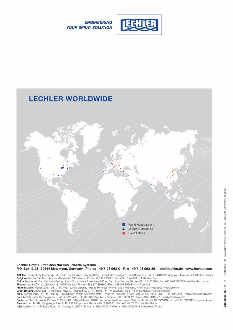
LECHLER WORLDWIDE
ASEAN: Lechler Spray Technology Sdn. Bhd. · No. 23, Jalan Teknologi 3/3A · Taman Sains Selangor 1 · Kota Damansara, PJU 5 · 47810 Petaling Jaya · Malaysia · [email protected]: Lechler S.A./N.V. · Avenue Mercator 6 · 1300 Wavre · Phone: +32 10 225022 · Fax: +32 10 243901 · [email protected]: Lechler Intl. Trad. Co. Ltd. · Beijing · Rm. 418 Landmark Tower · No. 8 Dong San Huan Bei Lu · Phone: +86 10 84537968, Fax: +86 10 84537458 · [email protected]: Lechler Oy · Jäspilänkatu 18 · 04250 Kerava · Phone: +358 207 856880 · Fax: +358 207 856881 · [email protected]: Lechler France, SAS · Bât. CAP2 · 66-72, Rue Marceau · 93558 Montreuil · Phone: +33 1 49882600 · Fax: +33 1 49882609 · [email protected] Britain: Lechler Ltd. · 1 Fell Street, Newhall · Sheffield, S9 2TP · Phone: +44 114 2492020 · Fax: +44 114 2493600 · [email protected]: Lechler (India) Pvt. Ltd. · Plot B-2 · Main Road · Wagle Industrial Estate · Thane (W) - 400604 · Phone: +91 22 40634444 · Fax: +91 22 40634498 · [email protected]: Lechler Spray Technology S.r.l. · Via Don Dossetti 2 · 20080 Carpiano (Mi) · Phone: +39 02 98859027 · Fax: +39 02 9815647 · [email protected]: Lechler S.A. · Avda. Pirineos 7 · Oficina B7, Edificio Inbisa I · 28700 San Sebastián de los Reyes, Madrid · Phone: +34 91 6586346 · Fax: +34 91 6586347 · [email protected]: Lechler AB · Kungsängsvägen 31 B · 753 23 Uppsala · Phone: +46 18 167030 · Fax: +46 18 167031 · [email protected]: Lechler Inc. · 445 Kautz Road · St. Charles, IL. 60174 · Phone: +1 630 3776611 · Fax: +1 630 3776657 · [email protected]
Lechler GmbH · Precision Nozzles · Nozzle SystemsP.O. Box 13 23 · 72544 Metzingen, Germany · Phone: +49 7123 962-0 · Fax: +49 7123 962-301 · [email protected] · www.lechler.com