Nozzle Design for Low-Pressure Micro Abrasive Waterjet Blasting … · Nozzle Design for...
20
Nozzle Design for Low-Pressure Micro Abrasive Waterjet Blasting via CFD Simulations Evren Bayraktar* a , Ekrem ¨ Ozkaya b , Raphael M¨ unster a , Dirk Biermann b and Stefan Turek a a Institute of Applied Mathematics (LS III), TU Dortmund Vogelpothsweg 87, D-44227 Dortmund, Germany b Institute of Machining Technology (ISF), TU Dortmund Baroper Str. 301, D-44227 Dortmund, Germany E-mail: [email protected] Abstract Waterjet technology has been extensively used in machining processes since 1970’s, and in the last years it has evolved to a precision machining tool for mi- cro workpieces, namely micro abrasive-waterjet blasting (μAWJB); neverthe- less, as a finishing process to remove micro-burrs it has not been yet developed. Our experimental studies on low-pressure μAWJB showed that conventional nozzles which are used for micro abrasive air jet blasting are subject to clog- ging at the mixing chamber. In this study, the venturi principle is exploited in order to obtain a novel nozzle design which will not lead to the clogging problem. The factors are considered as follows: the volumetric flow rate, the contraction–expansion ratios, the length of the cylindrical throat and the lo- cation of the attached (side) pipe. Various geometries are considered and a number of numerical simulations are performed to analyze these factors so that a nozzle which is suitable for low-pressure μAWJB can be constructed in light of the numerical results. The nozzle which is chosen in accordance with the numerical findings is proven to be operational with experimental studies. 1
Transcript of Nozzle Design for Low-Pressure Micro Abrasive Waterjet Blasting … · Nozzle Design for...
Nozzle Design for Low-Pressure Micro Abrasive
Waterjet Blasting via CFD Simulations
Evren Bayraktar*a, Ekrem Ozkayab, Raphael Munstera,
Dirk Biermannb and Stefan Tureka
a Institute of Applied Mathematics (LS III), TU Dortmund
Vogelpothsweg 87, D-44227 Dortmund, Germany
b Institute of Machining Technology (ISF), TU Dortmund
Baroper Str. 301, D-44227 Dortmund, Germany
E-mail: [email protected]
Abstract
Waterjet technology has been extensively used in machining processes since
1970’s, and in the last years it has evolved to a precision machining tool for mi-
cro workpieces, namely micro abrasive-waterjet blasting (µAWJB); neverthe-
less, as a finishing process to remove micro-burrs it has not been yet developed.
Our experimental studies on low-pressure µAWJB showed that conventional
nozzles which are used for micro abrasive air jet blasting are subject to clog-
ging at the mixing chamber. In this study, the venturi principle is exploited
in order to obtain a novel nozzle design which will not lead to the clogging
problem. The factors are considered as follows: the volumetric flow rate, the
contraction–expansion ratios, the length of the cylindrical throat and the lo-
cation of the attached (side) pipe. Various geometries are considered and a
number of numerical simulations are performed to analyze these factors so
that a nozzle which is suitable for low-pressure µAWJB can be constructed in
light of the numerical results. The nozzle which is chosen in accordance with
the numerical findings is proven to be operational with experimental studies.
1
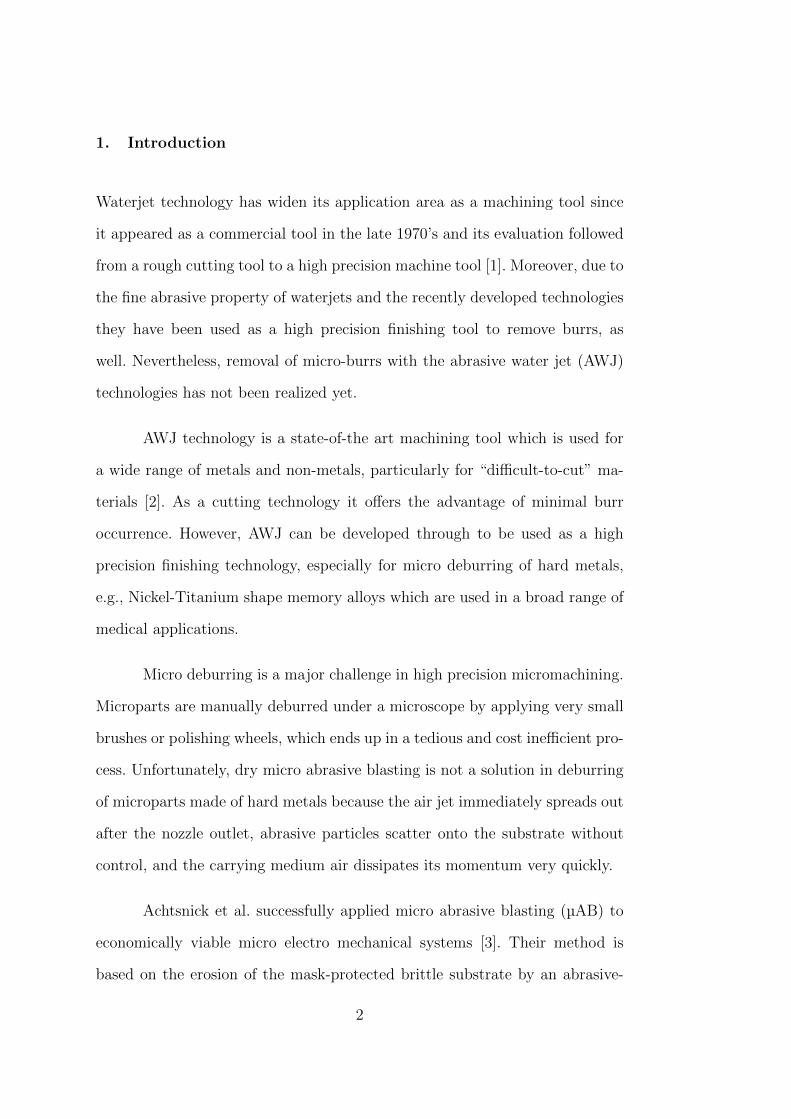
1. Introduction
Waterjet technology has widen its application area as a machining tool since
it appeared as a commercial tool in the late 1970’s and its evaluation followed
from a rough cutting tool to a high precision machine tool [1]. Moreover, due to
the fine abrasive property of waterjets and the recently developed technologies
they have been used as a high precision finishing tool to remove burrs, as
well. Nevertheless, removal of micro-burrs with the abrasive water jet (AWJ)
technologies has not been realized yet.
AWJ technology is a state-of-the art machining tool which is used for
a wide range of metals and non-metals, particularly for “difficult-to-cut” ma-
terials [2]. As a cutting technology it offers the advantage of minimal burr
occurrence. However, AWJ can be developed through to be used as a high
precision finishing technology, especially for micro deburring of hard metals,
e.g., Nickel-Titanium shape memory alloys which are used in a broad range of
medical applications.
Micro deburring is a major challenge in high precision micromachining.
Microparts are manually deburred under a microscope by applying very small
brushes or polishing wheels, which ends up in a tedious and cost inefficient pro-
cess. Unfortunately, dry micro abrasive blasting is not a solution in deburring
of microparts made of hard metals because the air jet immediately spreads out
after the nozzle outlet, abrasive particles scatter onto the substrate without
control, and the carrying medium air dissipates its momentum very quickly.
Achtsnick et al. successfully applied micro abrasive blasting (µAB) to
economically viable micro electro mechanical systems [3]. Their method is
based on the erosion of the mask-protected brittle substrate by an abrasive-
2
laden air jet. They need the mask-protection due to the high scattering of
abrasive particles, which exhibits another difficulty in micromachining. In or-
der to avoid this difficulty, we consider to exploit low-pressure micro abrasive
waterjet blasting µAWJB.
The process of µAWJB exhibits many challenges in (i) application,
(ii) mathematical modeling, (iii) numerical simulation. In the application
stage, very commonly encountered problems are sudden changes in µAWJ flow
characteristics, poor flowability and clumping of fine abrasives, and nozzle clog-
ging due to the wetting of abrasives caused by back-splash, which all demand
an optimum nozzle design. Three-phase (water-particle-air) µAWJ is one of
the most complex flow phenomena due to the solid-liquid, solid-solid and gas-
liquid interactions. Additional to challenges of modeling the flow dynamics, the
erosion of the surface has to be modeled with an appropriate material removal
model. And, the coupled mathematical model has to be solved with accurate
and efficient numerical methods.
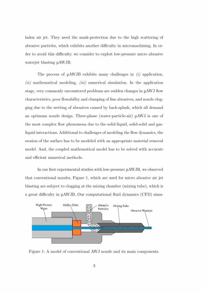
In our first experimental studies with low-pressure µAWJB, we observed
that conventional nozzles, Figure 1, which are used for micro abrasive air jet
blasting are subject to clogging at the mixing chamber (mixing tube), which is
a great difficulty in µAWJB. Our computational fluid dynamics (CFD) simu-
Figure 1: A model of conventional AWJ nozzle and its main components.
3
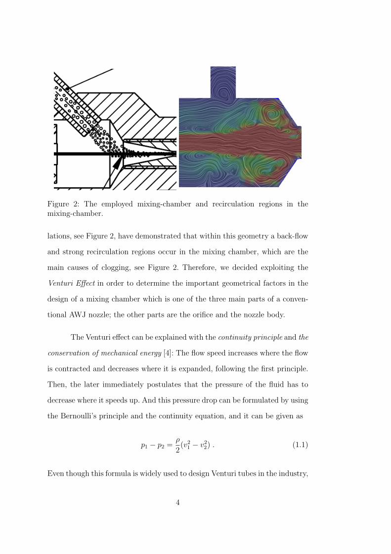
Figure 2: The employed mixing-chamber and recirculation regions in themixing-chamber.
lations, see Figure 2, have demonstrated that within this geometry a back-flow
and strong recirculation regions occur in the mixing chamber, which are the
main causes of clogging, see Figure 2. Therefore, we decided exploiting the
Venturi Effect in order to determine the important geometrical factors in the
design of a mixing chamber which is one of the three main parts of a conven-
tional AWJ nozzle; the other parts are the orifice and the nozzle body.
The Venturi effect can be explained with the continuity principle and the
conservation of mechanical energy [4]: The flow speed increases where the flow
is contracted and decreases where it is expanded, following the first principle.
Then, the later immediately postulates that the pressure of the fluid has to
decrease where it speeds up. And this pressure drop can be formulated by using
the Bernoulli’s principle and the continuity equation, and it can be given as
p1 − p2 =ρ
2(v21 − v22) . (1.1)
Even though this formula is widely used to design Venturi tubes in the industry,
4
our CFD simulations show that it is far away from being accurate.
First, two different Venturi tubes, see Figure 3, are considered to show
the effect of geometry on the suction efficiency, the first one being symmetric
about the axis of the suction pipe, considering only the parts: conical con-
vergent, cylindrical throat and conical convergent; the second one is with a
different conical divergent. Then, flow fields are simulated in these geometries
and the preferable geometry is determined, and by changing the location of
the side pipe on the preferred Venturi tube the geometry is optimized for an
efficient suction and easy manufacturing. Later, a comparative study is done
to show the effect of volumetric flow rate; for this purpose, the volumetric flow
rate is reduced to one forth of the initially used value. As the last we stud-
ied the effect of increasing the contraction and expansion ratios by reducing
the diameter of the cylindrical throat. Additionally, the effect of the cylindri-
cal throat’s length is taken into account. The accuracy of the calculations is
demonstrated with a grid dependency study. And, the flow with particles is
simulated to show the influence of the particles on the flow field.
2. Numerical Computations
2.1. Effect of the Geometry
The two geometries in Figure 3 are studied by performing moderately detailed
CFD simulations. The both meshes have 33408 cells resulting in fairly large
number of unknowns, ≈ 280000, with Q2/P1 finite-element pairs. The spatial
resolution is fine enough to obtain a resolved flow field with many flow features;
nevertheless, it is not sufficient to claim that the results are already fully grid
independent.
5

The inflow is prescribed over the whole inlet area with a parabolic
profile whose maximum velocity is normal to the inlet (z-coordinate) and has
the value 0.5 m/s. The prescribed inflow profile results into a volumetric flow
rate of 0.785 cm3/s, which is on the order of the estimated low rate values for
experimental studies.
For all the simulations in this study, initially a zero flow is prescribed in
the domain and the lid of the side pipe is closed. Then, the flow field has been
simulated for 1.5 s with the lid being closed and when the flow is sufficiently
developed, the lid is opened; later, flow has been simulated for another 2.0 s
and altogether flow is simulated for 3.5 s that is not long enough to see the – if
it ever exists – periodic behavior of the flow, but it is sufficient to characterize
the flow in the side pipe. At this stage, characterization is only in the flow
direction in the side pipe, either outward or inward, i.e., suction or ejection.
The main difference in the geometries is the angle of expansion at the
Figure 3: The Venturi tubes.
6
conical divergent. In the first geometry the conical divergent is the symmetry
of the conical convergent with respect to the axis of side pipe (y-axis) which
contracts from a radius of 7 mm down to 2 mm in 3 mm axial distance. In the
second geometry, the conical convergent, the inlet cylinder, the side pipe (the
radius of 1 mm and the height of 7.8 mm) and the cylindrical throat (the length
of 10 mm) are identical, only the conical divergent is changed and expands from
2 mm to 7 mm in 38 mm axial distance.
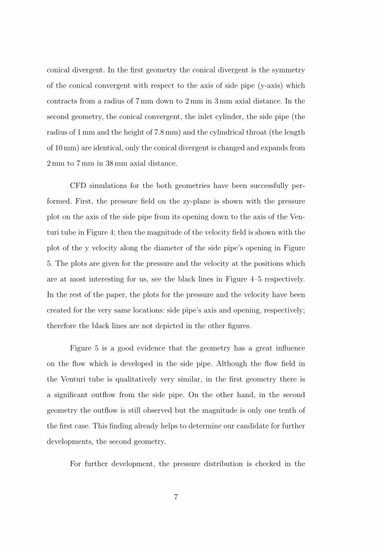
CFD simulations for the both geometries have been successfully per-
formed. First, the pressure field on the zy-plane is shown with the pressure
plot on the axis of the side pipe from its opening down to the axis of the Ven-
turi tube in Figure 4; then the magnitude of the velocity field is shown with the
plot of the y velocity along the diameter of the side pipe’s opening in Figure
5. The plots are given for the pressure and the velocity at the positions which
are at most interesting for us, see the black lines in Figure 4–5 respectively.
In the rest of the paper, the plots for the pressure and the velocity have been
created for the very same locations: side pipe’s axis and opening, respectively;
therefore the black lines are not depicted in the other figures.
Figure 5 is a good evidence that the geometry has a great influence
on the flow which is developed in the side pipe. Although the flow field in
the Venturi tube is qualitatively very similar, in the first geometry there is
a significant outflow from the side pipe. On the other hand, in the second
geometry the outflow is still observed but the magnitude is only one tenth of
the first case. This finding already helps to determine our candidate for further
developments, the second geometry.
For further development, the pressure distribution is checked in the
7
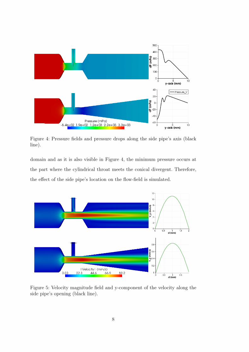
Figure 4: Pressure fields and pressure drops along the side pipe’s axis (blackline).
domain and as it is also visible in Figure 4, the minimum pressure occurs at
the part where the cylindrical throat meets the conical divergent. Therefore,
the effect of the side pipe’s location on the flow-field is simulated.
Figure 5: Velocity magnitude field and y-component of the velocity along theside pipe’s opening (black line).
8
The flow rate is also an important parameter having a strong influence
on the flow-field occurring in the side pipe. In cases where there is a suction,
it is well known that an increase in the flow rate leads to a stronger suction.
Nevertheless, if the direction of the flow can be changed by adjusting the flow
rate in the Venturi tube, this is an interesting topic to study. Indeed, this
presents another aspect to our future studies and for the moment to study the
influence of reducing the flow rate suffices our purposes, where a significant
outflow occurs at the side pipe. To study the influence of reducing the flow
rate is enough to see whether the designed Venturi tube still produces a suction
at the side pipe or does not.
2.2. Effect of the Side Pipe’s Location
Figure 4 shows that minimum pressure occurs where the cylindrical throat
meets the conical divergent. Following this fact, the side pipe is relocated to
the end of the cylindrical throat. One could also consider to attach the side pipe
near the conical divergent, and it might be even more effective; nevertheless,
regarding the manufacturing difficulties that design would be less preferable.
The CFD simulations were performed with the same number of un-
knowns, appr. 280000, for the both geometries, the comparative results are
given in Figure 6 and Figure 7.
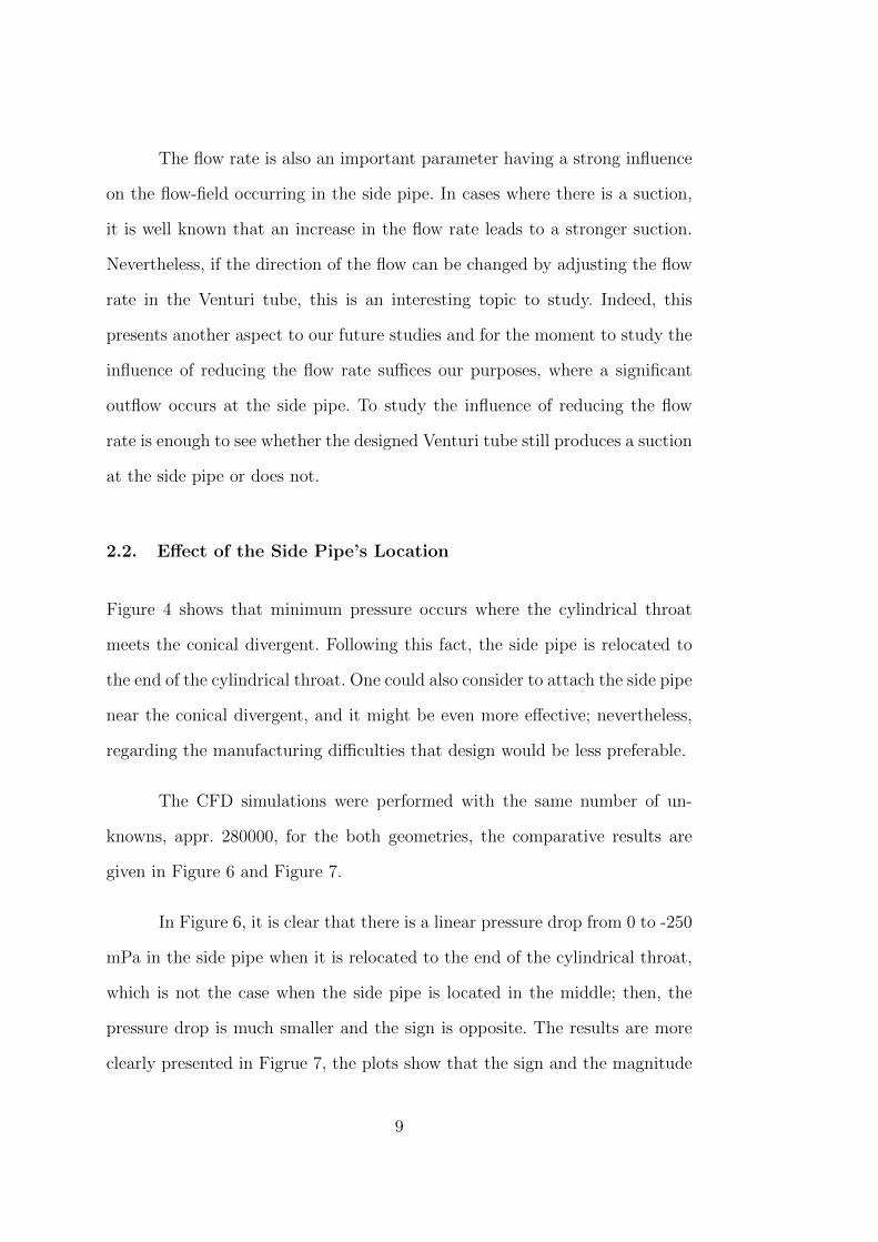
In Figure 6, it is clear that there is a linear pressure drop from 0 to -250
mPa in the side pipe when it is relocated to the end of the cylindrical throat,
which is not the case when the side pipe is located in the middle; then, the
pressure drop is much smaller and the sign is opposite. The results are more
clearly presented in Figrue 7, the plots show that the sign and the magnitude
9
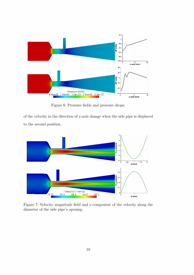
Figure 6: Pressure fields and pressure drops.
of the velocity in the direction of y-axis change when the side pipe is displaced
to the second position.
Figure 7: Velocity magnitude field and y-component of the velocity along thediameter of the side pipe’s opening.
10
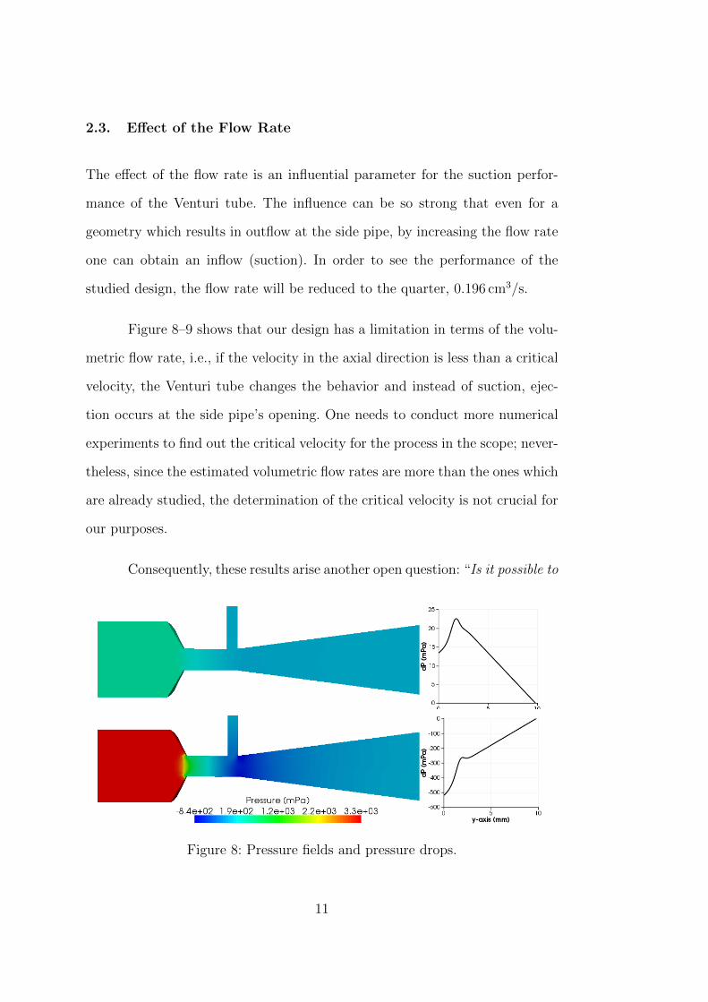
2.3. Effect of the Flow Rate
The effect of the flow rate is an influential parameter for the suction perfor-
mance of the Venturi tube. The influence can be so strong that even for a
geometry which results in outflow at the side pipe, by increasing the flow rate
one can obtain an inflow (suction). In order to see the performance of the
studied design, the flow rate will be reduced to the quarter, 0.196 cm3/s.
Figure 8–9 shows that our design has a limitation in terms of the volu-
metric flow rate, i.e., if the velocity in the axial direction is less than a critical
velocity, the Venturi tube changes the behavior and instead of suction, ejec-
tion occurs at the side pipe’s opening. One needs to conduct more numerical
experiments to find out the critical velocity for the process in the scope; never-
theless, since the estimated volumetric flow rates are more than the ones which
are already studied, the determination of the critical velocity is not crucial for
our purposes.
Consequently, these results arise another open question: “Is it possible to
Figure 8: Pressure fields and pressure drops.
11
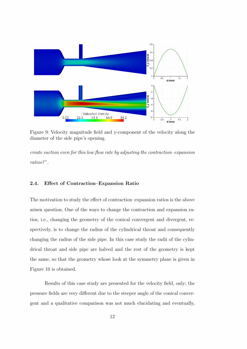
Figure 9: Velocity magnitude field and y-component of the velocity along thediameter of the side pipe’s opening.
create suction even for this low flow rate by adjusting the contraction–expansion
ratios?”.
2.4. Effect of Contraction–Expansion Ratio
The motivation to study the effect of contraction–expansion ratios is the above
arisen question. One of the ways to change the contraction and expansion ra-
tios, i.e., changing the geometry of the conical convergent and divergent, re-
spectively, is to change the radius of the cylindrical throat and consequently
changing the radius of the side pipe. In this case study the radii of the cylin-
drical throat and side pipe are halved and the rest of the geometry is kept
the same, so that the geometry whose look at the symmetry plane is given in
Figure 10 is obtained.
Results of this case study are presented for the velocity field, only; the
pressure fields are very different due to the steeper angle of the conical conver-
gent and a qualitative comparison was not much elucidating and eventually,
12
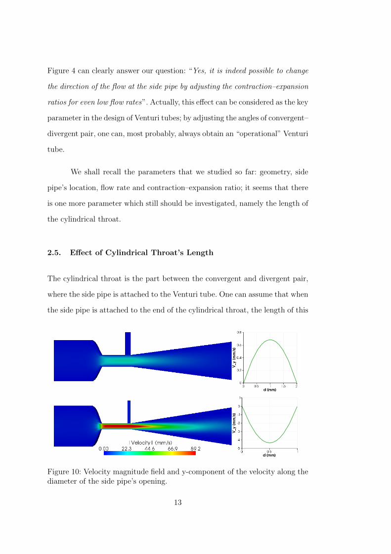
Figure 4 can clearly answer our question: “Yes, it is indeed possible to change
the direction of the flow at the side pipe by adjusting the contraction–expansion
ratios for even low flow rates”. Actually, this effect can be considered as the key
parameter in the design of Venturi tubes; by adjusting the angles of convergent–
divergent pair, one can, most probably, always obtain an “operational” Venturi
tube.
We shall recall the parameters that we studied so far: geometry, side
pipe’s location, flow rate and contraction–expansion ratio; it seems that there
is one more parameter which still should be investigated, namely the length of
the cylindrical throat.
2.5. Effect of Cylindrical Throat’s Length
The cylindrical throat is the part between the convergent and divergent pair,
where the side pipe is attached to the Venturi tube. One can assume that when
the side pipe is attached to the end of the cylindrical throat, the length of this
Figure 10: Velocity magnitude field and y-component of the velocity along thediameter of the side pipe’s opening.
13
part is not important within a reasonable range. To verify our assumption the
cylindrical throat is shortened to the half of its length and the flow is simulated
in this geometry.
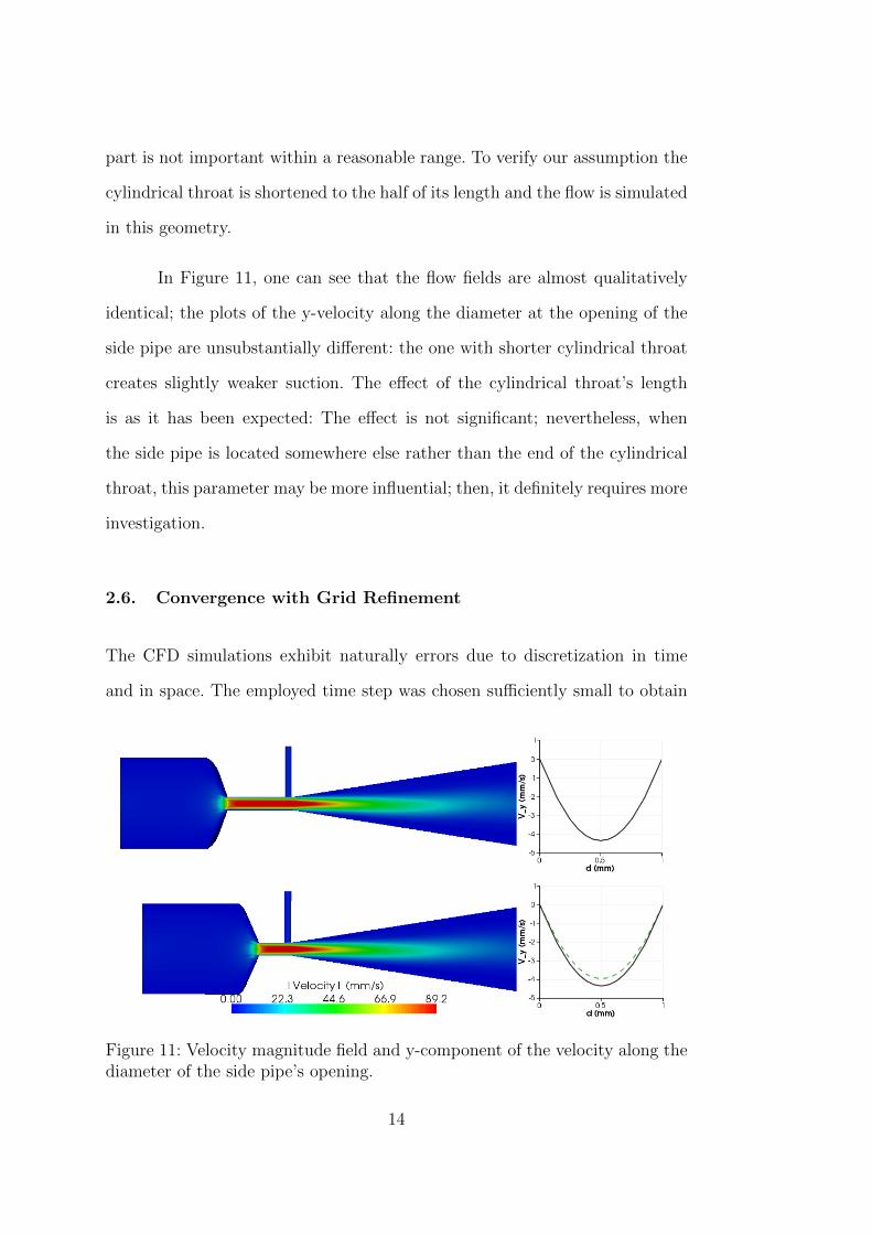
In Figure 11, one can see that the flow fields are almost qualitatively
identical; the plots of the y-velocity along the diameter at the opening of the
side pipe are unsubstantially different: the one with shorter cylindrical throat
creates slightly weaker suction. The effect of the cylindrical throat’s length
is as it has been expected: The effect is not significant; nevertheless, when
the side pipe is located somewhere else rather than the end of the cylindrical
throat, this parameter may be more influential; then, it definitely requires more
investigation.
2.6. Convergence with Grid Refinement
The CFD simulations exhibit naturally errors due to discretization in time
and in space. The employed time step was chosen sufficiently small to obtain
Figure 11: Velocity magnitude field and y-component of the velocity along thediameter of the side pipe’s opening.
14
numerical results which are independent of the chosen time step; on the other
hand, the employed spatial grid was intuitively chosen such that it provides
results with a certain accuracy and in a reasonable time scale. Therefore, we
chose the geometry with the smaller and longer cylindrical throat (the first
geometry in Subsection 2.5 ) and simulated the flow field once more on the
homogeneously refined grid.
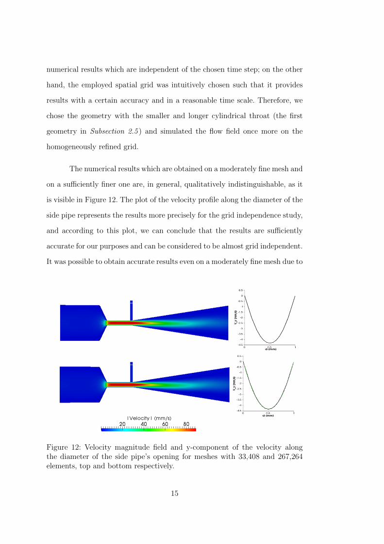
The numerical results which are obtained on a moderately fine mesh and
on a sufficiently finer one are, in general, qualitatively indistinguishable, as it
is visible in Figure 12. The plot of the velocity profile along the diameter of the
side pipe represents the results more precisely for the grid independence study,
and according to this plot, we can conclude that the results are sufficiently
accurate for our purposes and can be considered to be almost grid independent.
It was possible to obtain accurate results even on a moderately fine mesh due to
Figure 12: Velocity magnitude field and y-component of the velocity alongthe diameter of the side pipe’s opening for meshes with 33,408 and 267,264elements, top and bottom respectively.
15
the employed highly accurate finite element methods for the numerical solution
of the Navier-Stokes equations.
2.7. Effects of Particles on the Flow Field
In order to show the effect of particles on the flow field, the geometry which is
studied in the subsections 2.3, 2.4 and 2.5 is chosen to numerically study parti-
cle dynamics and the resulting flow behavior. We employed our in-house CFD-
solver that is developed based on FeatFlow solver package (www.featflow.de),
for which the adopted numerical methods are explained in detail by Turek [5],
to numerically simulate the flow with particles. The employed solver was com-
prehensively studied by Munster et al. [6], and its accuracy was proven to
be very satisfactory. In the numerical simulations the particles which have
a diameter of 150 µm are introduced at the side pipe’s opening at rest, and
their suction to the mixing tube is simulated. The simulation results with and
without particles are compared in Figure 13.
The streamline visualization of the flow fields with and without particle
presents a visible difference. The particles force the flow in the outward radial
direction such that the flow is less focused and expands through the side wall
of the mixing-tube. This shows that particle–flow-field interactions are influ-
ential on the flow field behavior and can not be neglected. Moreover, in this
case-study the particle simulation showed that the edge where the side pipe
and the diverging conical meet is prone to wear out; in general the wear and
the lifetime is an inevitable problem of AWJ nozzles. Nevertheless, particle
dynamics coupled flow simulations are a promising approach to determine the
wear zones and accordingly to improve the construction for a longer lifetime.
16
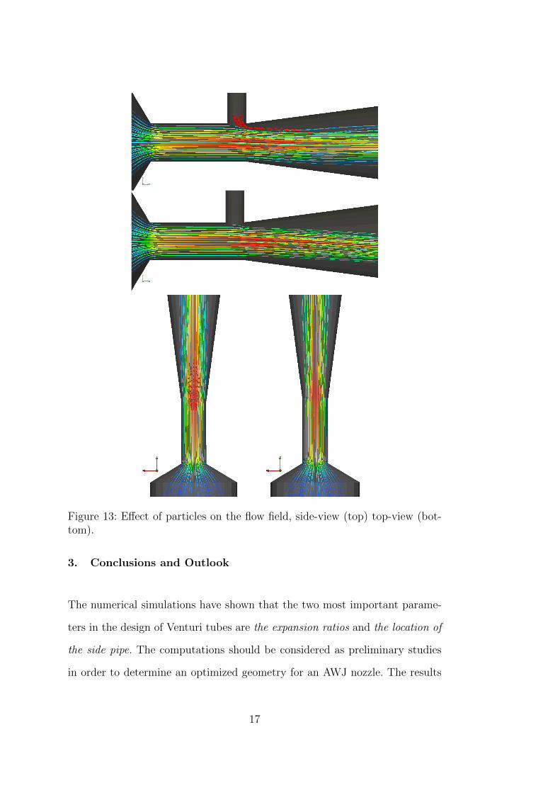
Figure 13: Effect of particles on the flow field, side-view (top) top-view (bot-tom).
3. Conclusions and Outlook
The numerical simulations have shown that the two most important parame-
ters in the design of Venturi tubes are the expansion ratios and the location of
the side pipe. The computations should be considered as preliminary studies
in order to determine an optimized geometry for an AWJ nozzle. The results
17
present a good guideline to design a mixing-chamber which can create a steady
suction of the abrasive particles; the following recommendations can be stated:
(i) A sudden contraction and expansion is not preferable; while sudden con-
traction creates a larger pressure drop, a sudden expansion results an unsteady
flow behavior and less pressure drop at the side pipe; (ii) the lowest pressure
zone in the domain is found to be at the location where the cylindrical throat
is attached to the conical divergent; therefore the side pipe should be attached
to the nozzle body about this point; (iii) in view of the particle simulations,
it is better to attach the side-pipe after the expansion starts, even though it is
less preferable from the manufacturing point of view, to avoid the wear at the
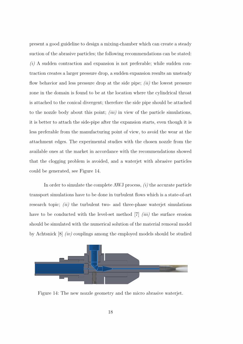
attachment edges. The experimental studies with the chosen nozzle from the
available ones at the market in accordance with the recommendations showed
that the clogging problem is avoided, and a waterjet with abrasive particles
could be generated, see Figure 14.
In order to simulate the complete AWJ process, (i) the accurate particle
transport simulations have to be done in turbulent flows which is a state-of-art
research topic; (ii) the turbulent two- and three-phase waterjet simulations
have to be conducted with the level-set method [7] (iii) the surface erosion
should be simulated with the numerical solution of the material removal model
by Achtsnick [8] (iv) couplings among the employed models should be studied
Figure 14: The new nozzle geometry and the micro abrasive waterjet.
18
and realized. The turbulent waterjet simulations with particles are of extreme
importance to simulate the low-pressure µAWJ blasting process as it requires
great efforts to measure particles’ velocity and distribution in the process.
Acknowledgments
The authors would like to thank the German Reasearch Foundation (DFG) for
supporting the work through the project: DFG GZ: BI 498/32-1, TU 102/39-1.
The support by the LiDOng team (ITMC, TU Dortmund) is gratefully ac-
knowledged.
References
[1] Liu H.-T. and Schubert E., Micro Abrasive-Waterjet Technology, Mi-
cromachining Techniques for Fabrication of Micro and Nano Structures,
(Eds: Mojtaba Kahrizi ), 2012, InTech, ISBN: 978-953-307-906-6.
[2] Liu H., Wang J., Kelson N. and Brown, R.J., A study of abrasive wa-
ter jet characteristics by CFD simulation, Journal of Material Processing
Technology, 153(-154), 2011, pp. 488–493.
[3] Karpuschewski B., Achtsnick M., Hoogstrate A.M., Simulation and im-
provement of the micro abrasive blasting process, 2008, Delft University
of Technology, The Netherlands.
[4] Ritter A., A Study of the Double Venturi Principle in Its Application to
High Speed Wind Tunnels, 1947, Georgia Institute of Technology.
[5] Turek S., Efficient Solvers for Incompressible Flow Problems: An Algo-
rithmic and Computational Approach, LNCSE 6, Springer, 1999.
19
[6] Munster R., Mierka O. and Turek S., Finite Element Fictitious Boundary
Methods (FEM-FBM) for 3D particulate flow, International Journal for
Numerical Methods in Fluids, 69, 2011, pp. 294–313.
[7] Turek S., Mierka O., Hysing S. and D. Kuzmin, Numerical study of a high
order 3D FEM-Level Set approach for immiscible flow simulation, Eds:
Repin S., Tiihonen T. and Tuovinen T., Computational Methods in Ap-
plied Sciences , 27, 65–70, Numerical methods for differential equations,
optimization, and technological problems, Springer.
[8] Achtsnick M., Geelhoed P.F., Hoogstrate A.M., Karpuschewski B., Mod-
elling and evaluation of the micro abrasive blasting process, Wear, 259,
2005, pp. 84–94.
20