Now with - IdealSpec · 8 COMMISSIONING & AUDITS ... 11.1 INLET STRAINERS ... Two Ø30mm holes are...
32
Now with Armitage Bioguard Helping to prevent the spread of pseudomonas bacteria A6682AA Markwik 21+ panel mounted mixer (demountable) with removable spout & Armitage Bioguard outlet A6735AA Markwik 21+ panel mounted mixer (demountable) with fixed spout & Armitage Bioguard outlet A6734AA Markwik 21+ deck mounted mixer (demountable) with fixed spout & Armitage Bioguard outlet Markwik 21+ Sequential lever operated thermostatic mixers INSTALLER: After installation please pass this instruction booklet to user IMPORTANT BEFORE CONNECTION, FLUSH WATER THROUGH PIPEWORK TO REMOVE ALL DEBRIS ETC. WHICH COULD DAMAGE THE VALVE MECHANISM INSTALLATION INSTRUCTIONS
Transcript of Now with - IdealSpec · 8 COMMISSIONING & AUDITS ... 11.1 INLET STRAINERS ... Two Ø30mm holes are...

Now with
ArmitageBioguard
Helping to preventthe spread ofpseudomonas
bacteria
A6682AA Markwik 21+ panel mounted mixer (demountable) with removable spout & Armitage Bioguard outletA6735AA Markwik 21+ panel mounted mixer (demountable) withfixedspout&ArmitageBioguardoutletA6734AA Markwik 21+ deck mounted mixer (demountable) withfixedspout&ArmitageBioguardoutlet
Markwik 21+ Sequential lever operated thermostatic mixers
INSTALLER: After installation please pass this instruction booklet to user
IMPORTANTBEFORE CONNECTION, FLUSH WATER THROUGH PIPEWORK TO REMOVEALL DEBRIS ETC. WHICH COULD DAMAGE THE VALVE MECHANISM
INSTALLATIONINSTRUCTIONS
2
TABLE OF CONTENT1 TABLE OF CONTENT ...................................................................................................22 DESCRIPTION ..............................................................................................................33 PRODUCT BOX CONTENTS ......................................................................................3
3.1 PANEL MOUNTED MIXER DIMENSIONS ..............................................................................43.2 DECK MOUNTED MIXER DIMENSIONS ...............................................................................4
4 WATER SUPPLY CONDITIONS....................................................................................54.1 WATER REGULATIONS .........................................................................................................54.2 INTRODUCTION .....................................................................................................................54.3 SUPPLY PRESSURE REQUIREMENTS ................................................................................54.4 HEALTHCARE ESTABLISHMENTS........................................................................................5
5 INSTALLATION GUIDE .................................................................................................65.1 PANEL MOUNTED MIXER ......................................................................................................65.2 DECK MOUNTED MIXER .......................................................................................................65.3 FLUSHING THE PIPEWORK ..................................................................................................75.4 FIXATION OF HANDLE ...........................................................................................................7
6 OPERATION ..................................................................................................................87 THERMAL SHOCK .......................................................................................................88 COMMISSIONING & AUDITS .......................................................................................9
8.1 THE PURPOSE OF COMMISSIONING: .................................................................................98.2 COMMISSIONING PROCESS (SEE DECISION TREE FC1) .................................................98.3 AUDIT CHECKS ON TMV‘S ..................................................................................................118.4 AUDIT PROCEDURE ............................................................................................................128.5 IN-FIELD `COLD WATER ISOLATION`(CWI) TEST .............................................................12
9 SERVICING - TVM3 SCHEME ....................................................................................139.1 FREQUENCY OF REGULAR SERVICING ...........................................................................13
10 MAINTENANCE ..........................................................................................................1410.1 ADJUSTMENT OF THE MIXED TEMPERATURE ................................................................1410.2 REMOVAL AND INSPECTION OF CARTRIDGE ..................................................................1510.3 THERMOSTATIC CARTRIDGE AGEING ..............................................................................1510.4 ARMITAGE BIOGUARD OUTLET .........................................................................................1610.5 OUTLET CLEANING .............................................................................................................1610.6 SPOUT REMOVAL ................................................................................................................1610.7 DEMOUNTING MIXER ..........................................................................................................1810.8 DISINFECTION SOLUTION ..................................................................................................19
11 INTEGRAL ISOLATION VALVES ...............................................................................2011.1 INLET STRAINERS ...............................................................................................................2111.2 DECK MIXER FLUSHING PROCEDURE .............................................................................2211.3 PANEL MIXER FLUSHING PROCEDURE ............................................................................23
12 COMBINED CHECK VALVE REGULATORS .............................................................2413 MARKWIK 21+ ACCESSORIES .................................................................................2514 SPARE PARTS PANEL MOUNTED MIXER ...............................................................2615 SPARE PARTS LIST PANEL MOUNTED MIXER.......................................................2716 SPARE PARTS DECK MOUNTED MIXER .................................................................2817 SPARE PARTS LIST DECK MOUNTED MIXER ........................................................2918 CLEANING CHROME SURFACES ............................................................................30

3
3 PRODUCT BOX CONTENTS
2 DESCRIPTION
This instruction booklet covers both panel and deck mounted, thermostatically controlled, sequential,lever operated mixers. The mixers are designed to provide water from ambient cold up to a safe maximum temperature for hand wash. They have a built-in thermal shock feature, using the special tool provided, the maximum blend stop can be overridden up to the full hot water supply temperature in the system.(See section 7) The products are fitted with Armitage Bioguard ‘anti-microbial copper lined’ outlets, reducing the opportunity for bio-film attachment.
The mixers have integral isolating valves and strainers and the thermostatic cartridge also has integral strainers.Combined check valve regulators (6.62 l/min) are located in the front of each inlet (See section 12)The hot water side of the body and inlets are thermally insulated to ensure the surfaces are kept at a safe temperature during operation.
The panel mounted mixer is intended to be installed on duct panel walls with a thickness of 13 – 27mm. The deck mounted mixer is intended to be installed on the deck of basins or the worktop housing inset basins with a thickness of 1 – 40mm.
Two Ø30mm holes are required to be cut in the panel or worktop at 200mm centres.
Markwik 21+ panel & Deck mounted mixer (demountable)
Mixers + fixing and handles kits
Deck Mixer
Panel Mixer Lever kit
x 2

4
153
170
Ø50
thread G3/4thread G1/2Ø15.20±0.05
285
188
5015
258 CRS 200
178
In healthcare applications the height of the fixationholes above the “waste appliance” should be selectedto create the recommended “activity space” asdefined in HBN 00-10 Part C, typically 150mm – 200mm for a basinand 250mm – 300mm for a surgeon’s scrub up trough.
226
135 CRSthread G1/2(hole size 30MM)
47
panel thickness 13-27
Ø62
91
36
200 crs
258
119
1783.1 Panel mounted mixer dimensions
IMPORTANT: Prior to installing mixer, ensure that any existing thermostatic mixing valves (TMVs)thatmaybefittedareremoved
3.2 Deck mounted mixer dimensions

5
4 WATER SUPPLY CONDITIONS
4.2 Introduction
4.1 Water regulations
4.3 Supply Pressure Requirements
This sequential thermostatic lever operated mixer is manufactured to the highest standards and has ap-proval to TMV3 which permits it to be installed in healthcare establishments such as hospitals, nursing homes and residential care homes. When installed in healthcare establishments the supply conditions detailed in Table 1 must be observed and the commissioning and servicing requirements detailed on section 8 & 9 must be followed.
For other installations this is not a requirement.
Thefittingscoveredbythisinstallationandmaintenanceinstructionshouldbeinstalledinaccordance with the water regulations published in 1999*, therefore Armitage Shanks would stronglyrecommendthatthesefittingsareinstalledbyaprofessionalinstaller*A guide to the Water Supply (Water Fittings) Regulations 1999 and the Water Byelaws 2000, Scotland is published by WRAS (Water Regulations Advisory Scheme) Fern Close, Pen-y-Fan Industrial Estate, Oakdale, Newport, NP11 3EH.ISBN 0-9539708-0-9
4.4 Healthcare EstablishmentsIn accordance with the NHS model engineering specifications DO8 this valve has approval for the following applications: High Pressure HP- -WE Low Pressure LP- -WE
For this type of application the following supply conditions must apply:
Operating pressure range: High Pressure Low Pressure
Maximum static pressure 10 bar 10 bar
Flow pressure hot and cold 1 to 5.0 bar 0.6 to 1.0 bar
Hot supply temperature 55 to 65 °C 55 to 65 °C
Cold supply temperature 5 to 20 °C 5 to 20 °C
Table 1 Supply conditions for healthcare establishments
Effectively this means:Differential between HOT and COLD inlet temperatures ( ∆t ) must be 32C° min and 60C° maxDifferential between HOT inlet temperature and MIXED temperature ( ∆t ) must be 11C° absolute mini-mum but > 14C° preferredSee 8.3 Audit checks on TMV’s.
Note:Fittings operating outside these conditions cannot be guaranteed by the scheme to operate as TMV3.
*52°C absolute minimum can be used but not recommended
This mixer is designed to be installed on all types of plumbing systems.Hot and cold water supply pressures should be reasonably balanced, however, the mixer will functionwithin specification on unequal pressures up to 5 :1.The mixer has integral isolating valves which permit servicing of the strainer, combined check valve regulator & thermostatic cartridge. They are also used for Cold water isolation testing.
The minimum pressure for the correct thermal operation is 0.6 bar.

6
5 INSTALLATION GUIDE
The panel mounted mixer is designed for panel mounting on a duct wall of maximum thickness 27mm. For thicker panels the rear of the panel will require a counterbore of 62mm or greater
Cut two Ø30mm holes horizontally aligned to 200mm centres. For the panel mountedmixer - See section 3.1 for height positioning of mixer over a “waste appliance”.
Loosen the chrome shrouds and insert the fitting as shown above with the wall plates and seals to the front of the wall. Fit the slip washers and do up the backnuts to a torque of 25 Nm. Screw the shrouds onto the wall plates.
Connect the plumbing using G1/2” swivel couplers. Installation - panel mounting
200 mm
Ø30 nominal
backnut
slip washer
wall plate
shroud
seal
DO NOT apply heat near this product. Heat generated by soldering could damage plastic parts and seals.
Check that all joints are securely tightened, test for leaks.
5.2 Deck mounted mixer
5.1 Panel mounted mixer
backnut
,‘O‘Seal
Ø30 nominal
shroud
The deck mounted mixer is designed to be deck mounted on a countertop of maximum thickness 40mm
Cut two Ø30mm holes horizontally aligned to 200mm centres.
With the base ‘O’ Seals fitted, place the inlet tails through the tap holes, fit the backnuts and tighten to 25Nm torque.
Connect the plumbing using Ø15mm compression connection.
Can be fitted onto a basin with holes as described above.

7
5.3 Flushing the pipework
5.4 Fixation of handle
IMPORTANT NOTE:Before operating the products, it is strongly recommended to flush the pipe work to remove any residuesor debris remaining after installation. Both panel and deck mixer purging kits are available for this purpose (See 11.2) The purging kits also provide the facility to obtain water supply temperatures at the inlets
1. To prevent damage, mixers are supplied without the handle fitted. To fit the handle, first carefully prise off plastic protective cover from cartridge spindle and discard. (Use a small flat bladed screwdriver if necessary)
2. Two rotational stop rings are fitted to the cartridge. Removal of these rings is not necessary for handle fixation. However the lower ring can be removed when temperature adjustment proves necessary.
3. Ensure tab of upper stop ring is firmly against clockwise rotation stop. If not, rotate the spindle clockwise until it is. The cartridge is now in the off position. (If necessary, use the spline drive in the handle to rotate the spindle.)
4. Ensure lower temperature adjustment stop ring is fitted to the cartridge with the small arrow pointing towards the left side of the body as shown (see Fig 2)
Fit handle to cartridge spindle with cut-out Arrow facing forwards towards the outlet. (See Fig 1)
5. Fit handle screw and tighten with a 4mm Allen Key.
6. Finally fit the bayonet cover cap to the handle
UpperLower
Fig 2
Fig 1

6 OPERATION
7 THERMAL SHOCK
off
warm
ThermalDisinfectionzone 90°
Maximum blendTemperature stop
cold
Normal range ofHandle movement 90°
Handle control positions.
Rotate the handle anti-clockwise. The delivered water will progress from cold through warm up to a maximum blend temperature of approximately 41°C
Safety Note: Care should be taken when carrying out the following procedure to avoid contact with hot water and hot surfaces.
For Thermal disinfection, this fitting is equipped with a built in thermal shock feature. This allows the maximum blend stop to be overridden using the hot water supply temperature in the system.
1. To activate, twist the handle cap anticlockwise and remove2. Screw the override tool fully into the threaded port on top of the handle 3. Carefully lift the override tool and turn the handle fully anticlockwise
L i f t over r ide t o o l , t h e n rotate handle anticlockwise
8

8 COMMISSIONING & AUDITS
THERMAL SHOCK CONTINUED
Once the thermal shock is complete, simply unscrew and remove the override tool, return the handle to the off position and refit the handle capPerform the Cold water isolation (CWI) test (see section 8.5) to ensure the product is working correctly
Temperature Disinfectiontime
60°C65°C70°C
20 minutes10 minutes5 minutes
The following procedure should be conducted after installation to ensure the product is functioning correctly.
8.1 The Purpose of Commissioning:• To confirm the correct designation of product versus application.• To confirm the correct supply water conditions for the product / installation.• To adjust the mixed temperature if necessary to suit the water supply conditions of the installation.• To check the product is performing properly.• To start an audit log and record appropriate data.
These prododucts are factory set at 40°C ± 1°C with supplies of circa; 3 bar balanced pressure andtemperatures of 15°C cold & 65°C hot (i.e. an inlet ∆t of 50C° & hot / mix ∆t of 24C°)For supply requirements, see 4 Water Supply Conditions.
8.2 Commissioning Process (see decision tree FC1)• Establish that the supply conditions are within the requirements outlined above. If not investigate.• When conditions are acceptable record them, together with hot and cold temperatures. Establish ∆t.
Check the outlet mix temperature is within 41°C ± 2°C, if not (probably due to ∆t > 5C° difference tofactory setting) adjust appropriately. (see section 10.1)• If mixed temperature is correct undertake an ‘in field’ cold water isolation (CWI) test: (see section 8.5) Pass - restore supply and record mixed temperature, Fail - See 8.5 in-field ‘Cold Water Isolation’ test.
9

10
8.2 cont. Commissioning process (decision tree FC1)
NOTES:MWT - Maximum Working TemperatureCommissioning; Supply Conditions should be recorded
NOTE:Factory settings are:Inlet t = H - C = 65-15 = 50°CHot/Mix t = 65-41 = 24°C
∆∆
pass
accept
record mixed temperature
re-set mixed to 41 C 0/-2°Cº +
follow setting or maintenance
instructionsMWT 41 C (+0 / -º 2ºC)
check the supply conditionspressure 0.2 - 5.0 bar & temperature <20ºC & >55ºC
record supply conditionsand ∆t for the hot & cold investigate
YES
YES
YES
NO
NO
NOfail test
undertake in-field cold waterisolation test - see see 8.5
Achieved 41 ± 2°C?

11
Audit of Supplies To Fittings (FC3)
∆t>5ºC
is supply temperaturesame as previous audit?
YES
YES YES
YES
YES
YES
YES
NO
NO
NO
NO
NO
NO
record stable state supplytemperature (5 - 20 C)º
cold <20in 2 minutes
ºC supply pressuresare appropriate
hot>55in 1 minute
ºC
record stable state supplytemperature (55 - 65ºC)
is supply temperaturesame as previous audit?
insignificant changedifference <5 C∆t º
>65ºC
temporary changeof known cause
long term or permanentchange - consider
recommisioning of thermofitting(s)
implications to terminal fittings
investigate system issue
no action.retest when
conditions normaliseno action
go to D-08 field test audit 8.4or commissioning 8.2
follow commissioninginstructions see 8.0
8.3 Audit Checks on TMV's The purpose of a performance audit of a product is:
To check the product continues to perform properly.To flag the need for the product to be adjusted due to supply condition changes or mechanism ageing.To ultimately identify the need for product maintenance.
Note - Additionally these audits facilitate regular verification of the supply conditions in accordance with HTM 04 requirements. (See decision tree FC3)
8.3 Audit Checks on TMV‘s

12
Verify the water supplies conditions are similar to when the product was commissioned i.e. inlet ∆t as previous + / - 5
(s
Pass - restore the cold supply and move on to check the mix temperature.
Mixed Temperature is as commissioned Accept and record the temperature.
C°
If inlet ∆t differs from the commissioning ∆t by < 5C° carry out field 'cold water isolation' (CWI) test as D-08: 2009.
±2C°
2nd & subsequent instances follow maintenance instructions.
Note: If inlet ∆t change is > 5C consider the cause of the change, If it is seen as a long term or permanent change, re-commission the product. If however, it is only a temporary change, retest when normal conditions resume.
Note: If the product fails CWI test, refer to 8.5 and then re-commission the valve.
Note: If mixed Deviation > ±2C (1st instance) reset mix as instructions and redo the test from start.
ee 8.5 in field Cold Water Isolation test failure.)
See 9.1 Adjustment of the mix temperature.
°
°
8.5 In-field 'Cold Water Isolation´(CWI) test.
.
,
Fitting Field Test Audit (FC2)
go to commissioning FC1 (8.2)
2nd instancefollow maintenance
instructions (section 10)
1st instancereset, follow
setting instructions
accept& record
mixed temp.
same as atcommissioning
2.0 C± ºdeviation from
previous >+2.0ºC
check mixedtemperature
restore cold
pass failsee 10
undertake the coldwater isolation test
see 8.5
water supplies same asprevious audit or
∆t change >5ºC
Note: To gain access to the cold waterisolating valves see section 11.Using a 5mm Allen Key, the isolationscrew can be rotated fully clockwise to isolate the cold water supply
Before commencing the CWI test, ensure:
1. The water supply conditions are met either: A. For commissioning a new product (see table 1, section 4). B. Or the inlet ∆t is within ±5°C to when the product was commissioned (see section 8.4)NOTE It is important that the hot temperature is greater than 55°C
2. Mixed water outlet temperature is correct (see Table2, selection 9)
8.4 Audit procedure (see decision tree FC2)

13
The purpose of servicing regularly is to monitor any changes in performance due to changes in either the system or the product. This may highlight the need to adjust either the supply system or the product. These products should be audited 6 to 8 weeks and again 12 to 15 weeks after commissioning. The results are to be compared against original commissioning settings.If there are no significant changes at the mixed temperature outlet then a 6 monthly servicing cycle may be adopted. Otherwise, servicing checks should be carried out more frequently (e.g. every 4 months).Follow the recommended auditing and maintenance procedures detailed in sections 8 & 10.During servicing, note the following:1
2.
3.
. Repeat the procedure of recording and checking supply temperatures. (The same type of measuring equipment should be used)
If the temperature has changed significantly from the previously recorded valves, the following should be checked:
When satisfied with the mixed outlet temperatures re-record the temperatures.
a.b.c.
All in-line or integral valve filters are clear of obstruction. All in-line or integral check valves are clean and working properly to prevent backflow. Any isolating valves are fully open.
d. The thermostat is free of debris
Table 2 A guide to maximum temperature sets
The need for servicing is normally identified as a result of the regular performance auditing.
To perform a CWI test, operate the product Then conduct the following procedure:
1. Record the steady state temperature of both hot and cold water supplies. Note the ∆t.2. Record the temperature of the mixed water at the outlet.3. Isolate the cold water supply (by rotating the isolating screw fully clockwise) & monitor the flow of water from the outlet.
If the flow ceases, CWI test passed:1. Restore the cold water supply by rotating the isolator screw 90° anti clockwise.2. Slide the shroud back & screw onto the wall plate. See Section 11 for Deck fitting3. Re-check the temperature of the stabilised mixed water at the outlet to ensure it is still correct.
Accept & record mixed temperature.
by rotating the lever fully to the right.
If there is an ongoing flow of water from the mixed water outlet, then 5 seconds after CWI collect the discharging water into a measuring vessel for 60 seconds. To pass the CWI test the volume of collected water should be less than 120ml.
If the product fails CWI test, see FC2 . Follow product maintenance and servicing instructions.
(see section 8) (see section 10)(see section 9)
Permitted maximum stabilisedtemperature recorded during sitetesting – excluding transient spikes
Maximum mixed watertemperature duringnormal operation
Application
41ºC 43ºCWashbasin
9 SERVICING - TVM3 SCHEME
9.1 FREQUENCY OF REGULAR SERVICING

14
10 MAINTENANCE
10.1 Adjustment of the mixed temperature
Note: Cartridge is factory pre-set at 40°+/- 1°C @3BarWith differing supply conditions may require adjustment in order to maintain set temperature
1. Twist the handle cap anticlockwise and lift it off 2. Unscrew the retaining screw using a 4mm Allen key and lift off the handle3. To adjust the max blend temperature lift, rotate and refit the maximum blend temperature stop ring. • To increase the temperature, rotate the ring anticlockwise • To reduce the temperature rotate the ring clockwise4. Upon successful completion of the temperature adjustment, conduct the Cold Water Isolation (CWI) test (See 8.5) to ensure the product is working correctly.5. Refit the Handle and cap and record the mixed temperature
Handle Cap
Screw
Handle
Rotate ring clock-wise to reduce max blend temperature
Maximum blend tem-perature stop ringF i t ted to car t r idge body spline
Rotate ring anticlockwise to increase max blend tem-perature
Metal Off-Stop ringFitted to small rotating cartridge spline

Handle Cap
Screw
Handle
15
10.2 Removal and inspection of cartridge
After checking that supply conditions are within the specified parameters (See section 4.3, Table 1), if the mixer malfunctions or should the test results fail to fall within the specified limits, consider replacing the cartridge with a new one.
Isolate the mixer with the integral isolation screws See section 11
Remove the handle as described in 10.1. Unscrew the cartridgefrom the body with a 36mm A/F deep socket. Inspect cartridge for damage.
Replace cartridge if necessary and re-assemble into body.
The replacement cartridge should be tightened to a torque of 15Nm
Replace lever handle (See section 5.3) and reinstate the supplies
After fitting the new cartridge start the test procedure from the section on commissioning
• Redo the Cold Water Isolation (CWI) test (See section 8.5)• Once satisfied with the CWI test, re check and if necessary, adjust the maximum mix temperature, (See section 10.1)• Record the mix temperature
The Thermostatic cartridge has built-in strainers, these shouldbe inspected and if necessary washed with clean water orreplaced (See section 15 & 16)
Sequential Thermo-static car-tridge
Maximum blend tem-perature stop
10.3 Thermostatic Cartridge Ageing
Following many years of normal service you may notice the following: 1. The need to carry out more frequent adjustment of mixed temperature. 2. The thermostatic element may not pass the CWI test.
These issues could be due to the ageing of the thermostat which loses some expansion capability over time.
These are the principle objectives of testing, as they serve to indicate to maintenance staff the declining performance capability of the thermostatic cartridge.
For this reason the audit testing flow chart highlights that 2nd Instance CWI test failure or 2nd instance mixed deviation even with stable ‘as commissioned’ supply conditions and correct inlet supply ∆t’s, is potentially the first indication of the need to replace the cartridge.
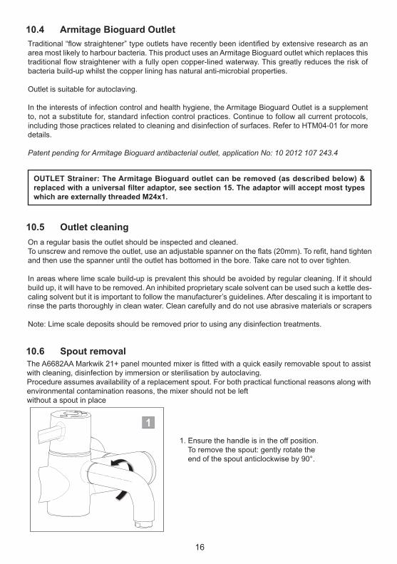
The A6682AA Markwik 21+ panel mounted mixer is fitted with a quick easily removable spout to assist with cleaning, disinfection by immersion or sterilisation by autoclaving.Procedure assumes availability of a replacement spout. For both practical functional reasons along with environmental contamination reasons, the mixer should not be left without a spout in place
1. Ensure the handle is in the off position. To remove the spout: gently rotate the end of the spout anticlockwise by 90°.
10.6 Spout removal
1
16
10.4 Armitage Bioguard Outlet
10.5 Outlet cleaning
Traditional “flow straightener” type outlets have recently been identified by extensive research as an area most likely to harbour bacteria. This product uses an Armitage Bioguard outlet which replaces this traditional flow straightener with a fully open copper-lined waterway. This greatly reduces the risk of bacteria build-up whilst the copper lining has natural anti-microbial properties.
Outlet is suitable for autoclaving.
In the interests of infection control and health hygiene, the Armitage Bioguard Outlet is a supplement to, not a substitute for, standard infection control practices. Continue to follow all current protocols, including those practices related to cleaning and disinfection of surfaces. Refer to HTM04-01 for more details.
Patent pending for Armitage Bioguard antibacterial outlet, application No: 10 2012 107 243.4
On a regular basis the outlet should be inspected and cleaned.To unscrew and remove the outlet, use an adjustable spanner on the flats (20mm). To refit, hand tighten and then use the spanner until the outlet has bottomed in the bore. Take care not to over tighten.
In areas where lime scale build-up is prevalent this should be avoided by regular cleaning. If it should build up, it will have to be removed. An inhibited proprietary scale solvent can be used such a kettle des-caling solvent but it is important to follow the manufacturer’s guidelines. After descaling it is important to rinse the parts thoroughly in clean water. Clean carefully and do not use abrasive materials or scrapers
Note: Lime scale deposits should be removed prior to using any disinfection treatments.
OUTLET Strainer: The Armitage Bioguard outlet can be removed (as described below) & replacedwithauniversalfilteradaptor,seesection15.Theadaptorwillacceptmosttypeswhich are externally threaded M24x1.

17
Additional spouts are available so during cleaning protocols an alternative spout can be fitted while theoriginal is removed. This insures continuity of use of the mixer.For additional spout part numbers, See section 13.
Cleaning / disinfecting / sterilising the removed spout.
Physical cleaning is only necessary if evidence of solid deposits e.g. calcium or similar can be seen around the outlet.
Disinfection can be achieved by immersing in an appropriate bactericidal solution, using this methodwe would strongly recommend removal of the Armitage Bioguard outlet from the spout prior to immer-sion.For disinfection solution See section 10.8.Sterilisation can be achieved by autoclaving for the desired period. Complete spout can be autoclaved (NB; the seals can withstand this process).
3. Gently pull the spout away from the body as shown.
Quarantine this spout for cleaning protocols.
Ensure replacement spout complies with cleaning protocols.
To refit a spout, reverse this procedure.
2. The spout should now be in the horizontal position as shown.
IMPORTANT: Donotleavethemixeroutletopenwithoutaspoutfitted.
2
3

In response to the new requirements of HTM 04-01 Addendum, the designs of these mixers have been enhanced to permit easy demounting of the mixer from the inlets.
This updated design permits quick & easy removal of the mixer for cleaning, disinfection and mainte-nance purposesPrior to commencing this procedure, you should have available either a replacement mixer (without inlets) or a pair of protective cover caps. See section 13.
Method for demounting mixers: 1. Isolate the hot and cold water supplies using the integral isolation valves. (See section 11) Operate lever to confirm water supplies are closed off. 2. Undo the 2 grub screws securing the mixer using a 3mm hexagon key. (Take care not to lose the screws). 3. Remove the mixer from the inlets, by gently pulling away as shown. Expect some trapped water to escape.4. During cleaning protocols: Fit cover caps to protect & seal the inlets (See section 13).5. To refit the mixer; reverse this procedure. Tighten screws securely
10.7 Demounting mixer
Take care to avoid damaging the inlet seals. Damage to these seals would compromise the insulate feature & affect the mixer’s thermostatic performance. See section 13 for spare “demountable seal kit”.
3
3
18

Disinfection by full immersion in an appropriate bactericidal solution is recommended for this assembly. Prior to immersion, the fitting should be clean and dismantled to a level that prevents air locking. The level of dismantling should be established as a result of practice and will be largely dependent upon the water quality and service life. As a minimum we recommend removal of the lever handle & thermo-static cartridge. Cleaning the cartridge strainer screens is important. All components can be immersed together unassembled. Disinfected mixers should be promptly replaced or stored using an appropriate method until required. For disinfection solution See section 10.8
For both practical functional reasons along with environmental contamination reasons, the inlets should not be left open
We recommend parts be immersed in an appropriate bactericidal solutionThe frequency of such disinfection actions will be derived from regular sampling carried out under the regime of the Responsible Person (Water). We would not expect to need greater than 6 monthly fre-quencies, hopefully considerably less.
The need for excessive use of this procedure would be indicative of the need for some root cause analy-sis as there could be some system or behavioural problems that need addressing.Recommended Disinfection Solutions For immersion we recommend the use of a 70% Ethanol solution for 10 minutes. NB: counter intuitively, greater than recommended concentrations are less effective not more ef-fective; take care to get the recommended concentration in line with the manufactures recommendation
10.8 Disinfection solution
IMPORTANT: Donotleavethemixerinletsopenwithoutabodyorcovercapsfitted.
3
19
Demounting mixers continued
Protective cover caps
Push the caps onto the inlets until they stop against the shoulder.Take care not to damage the o-ring seals.Secure the cap with grub screw as shown using a 3mm Hexagonal key. Leave the hot & cold supplies isolated.Cover caps should be disinfected / sterilised when necessary.

20
11 INTEGRAL ISOLATION VALVESThe integral isolation valves facilitate a number of activities:• Servicing the thermostatic cartridge• Cleaning or replacing the strainers• Audit Cold Water Isolation (CWI) test• Demounting the mixer from its inlets
To isolate the mixers, proceed as follows:1. On the panel mounted mixers, unscrew the wall shrouds and slide forward, on the deck mounted mixer remove the small index buttons at the base of the shrouds.2. Isolate both inlets by screwing isolation valves down fully using a 5mm Allen key in the clockwise direction.3. Reverse procedure to restore the water supplies and refit the shrouds / index buttons.

21
11.1 Inlet StrainersTo ensure trouble free operation of the fitting, the strainer elements should be checked and cleaned in accordance with the commissioning and servicing guide.
To access the strainer element, close the isolation valves and demount the mixer (see section 10.7)
Deckmountedfitting
1. Lift one piece chrome shroud off the inlet
2. To access the strainer, using two 25mm A/F spanners retain the bottom inlet and unscrew the top inlet assembly
3.The strainer element should be washed with clean water and refitted
4. Re-assemble the inlet
5. Re-fit the chrome shroud taking care to line up the small access hole in the base of the shroud with the isolation screw on the inlet.
1. Unscrew and remove the Chrome Panel Shrouds and pull the Chrome Sleeves forward off the inlet seals.2. Isolate both inlets by screwing the isolation valves down fully using a 5mm hexagon key in the clockwise direction. (Operate lever to confirm water supplies are closed off).3. Undo the 2 grub screws securing the mixer using a 3mm hexagon key. (Take care not to lose the screws).4. Remove the mixer from the inlets, by gently pulling forwards. Expect some trapped water to escape5. Unscrew and remove the strainers from the underside of the Inlets using a 5mm hexagon key.6. The strainers should be inspected and washed with clean water and can be Autoclaved or replaced as necessary7. Before re-assembling the strainers we recommend flushing the inlets with our purging and water sampling kit - A6899NU (not included)
3
Panelmountedfitting

22
11.2 Deck mixer Flushing procedure
IMPORTANT NOTE:Before operating the product, it is strongly recommended to flush the pipe work to remove any residues or debris remaining after installation. A purge kit is available for this purpose.
The purging kit also provides the facility to obtain water supply temperatures at the inlets.
Safety Note: Care should be taken when carrying out the following procedure to avoid contact with hot water and hot surfaces. We recommend the use of protective hand wear.
The following procedure should be used to flush out the pipework:1. Remove the strainer from the inlets as detailed in section 11.1 to gain access to the purging port.2. Screw the purging tool fully into the inlet port.3. Attach tubing to the purging tool and direct into the basin.4. Open the isolating valve and allow water to discharge into the basin until the water flows clean.5. Repeat on the both sides of the mixer so that both the hot and cold supplies are flushed.Once the system has been flushed, remove the purging kits and refit the strainers with the sealing washer facing upwards and the strainer mesh facing downwards.
Re-assemble the top inlets and Chrome Inlet Sleeves and secure the body back onto the inlets with a 3mm hexagon key
5
25
Tubing
Purging tool
Bottom deck inlet
5mm hexagon key

23
11.3 Panel mixer Flushing procedure
11
3
Safety Note: Care should be taken when carrying out the following procedure to avoid contact with hotwater and hot surfaces. We recommend the use of protective hand wear.
The following procedure should be used to flush out the pipework:1. Remove the strainer from the inlet with a 5mm hexagon key to gain access to the purging port.2. Screw the purging kit into the inlet port fully and then unscrew until the small indent on thepurging kit towards the front of the inlet as shown.3. Open the isolating valve and allow water to discharge into a vessel until the water flows cleanSuitable tubing can be push fitted onto the purging kits if required.4. Repeat on the both sides of the mixer so that the hot and cold supplies are both flushed.
Once the system has been flushed, remove the purging kits and refit the strainers using a 5mm Allenkey.Re-assemble the Chrome Inlet Sleeves and Panel Shrouds and secure the body back onto the inletswith a 3mm hexagon key.
Important!
Small indent on the purging kit must be aligned towards the front of the inlet.
24
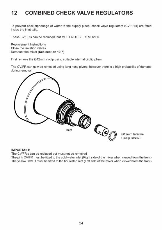
12 COMBINED CHECK VALVE REGULATORS
To prevent back siphonage of water to the supply pipes, check valve regulators (CV/FR’s) are fitted inside the inlet tails.
These CV/FR’s can be replaced, but MUST NOT BE REMOVED.
Replacement InstructionsClose the isolation valvesDemount the mixer (See section 10.7)
First remove the Ø12mm circlip using suitable internal circlip pliers.
The CV/FR can now be removed using long nose plyers; however there is a high probability of damage during removal.
Ø12mm IntermalCirclip DIN472
Inlet
IMPORTANT:The CV/FR’s can be replaced but must not be removedThe pink CV/FR must be fitted to the cold water inlet (Right side of the mixer when viewed from the front) The yellow CV/FR must be fitted to the hot water inlet (Left side of the mixer when viewed from the front)

13 MARKWIK 21+ ACCESSORIES
A6250AA Panel mount spout complete.With normal 135mm reach.Fitted with Armitage Bioguard outlet& o-rings at the mixer coupling end.See section 10.6
A6255AA Cover caps kit.To protect & seal the inlets legs whena mixer has been demounted & removed.See section 10.7
A6899NU Panel Flushing setSee section 11.3
A6898NU Deck Flushing setSee section 11.2
A6256AA Universal filter adaptor.Replaces the Armitage Bioguard outletto permit attachment of an outlet filter.Threaded M24x1 (internal).
A6252AA Panel mount spout complete.Short version with100mm reach.Fitted with Armitage Bioguard outlet& o-rings at the mixer coupling end.See section 10.6
25

26
14 SPARE PARTS PANEL MOUNTED MIXER
5
5b
20
1
2
3
19
1817
9
10
2122
2318
24
252126
2728
29
4
33
15
1413
1211
7
6
8
8
23
3017
31
For complete spout subassemblies,see section 13
16
32
For more information on spare parts why not visit our spare website:www.fastpart-spares.co.ukor contact customer care
fast t r a p

27
For more information on spare parts why not visit our spare website:www.fastpart-spares.co.ukor contact customer care
fast t r a p
15 SPARE PARTS LIST PANEL MOUNTED MIXER
Ref. Description Part No.1 Cap A861159AA2 Handle screw A961950NU3 Handle SET A861158AA4 Stopring A861122AA5 Sequential, thermostatic cartridge A861123AA5b O - ring set thermostatic cartridge + strainer set A861166NU6 Body --7 Outlet F960847AA8 Screw (Available in 30 set) --9 Escutcheon + O-ring A962346AA10 Side sleeve cpl. A861160NU11 O - ring Ø 11 x 2 A960942NU12 O - ring Ø 13 x 2 A861101NU13 Sleeve --14 Threaded nut M18x1,5 --15 Cap w. o - ring Ø 30 x 2 A861124NU16 Inlet Set A861161NU17 O-ring 17 x 2.5 A963143NU18 O - ring Ø 24 x 2,5 A961809NU19 Inlet insulator --20 Inlet Sleeve --21 Circlip A963143NU22a Combined CV&FR Ø10mm, cold water (pink) right side A861215NU22b Combined CV&FR Ø10mm, hot water (yellow) left side A861216NU23 O - ring Ø 12,42 x 1,78 A961332NU24 Isolations plug --25 O-ring dia 8.1 x 1.6 (single) - (available within item 16) A962345NU26 Wall plate E960633NU27 O-ring Ø51 x 2.4 E960632NU28 SLIP WASHER Ø60 X Ø25 X 2 E960631NU29 Backnut E960112NU30 Demountable seal kit with grub screws, o-rings & hex hey A861162NU31 O-ring Ø15 x 2.5 F961003NU32 Strainer A861172NU33 Override tool A860888NU

18
17
21
22
23
24
25
21
26
27
29
5
1
2
3
10
4
36
15
1413
1211
7
6
8
8
23
34
28
17
35
For complete spout subassemblies,see section 13
16
33
32
9
30
31
19
20
5b
28
16 SPARE PARTS DECK MOUNTED MIXER
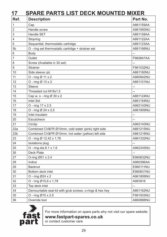
Ref. Description Part No.1 Cap A861159AA2 Handle screw A961950NU3 Handle SET A861158AA4 Stopring A861122AA5 Sequential, thermostatic cartridge A861123AA5b O - ring set thermostatic cartridge + strainer set A861166NU6 Body --7 Outlet F960847AA8 Screw (Available in 30 set) --9 Strainer F961032NU10 Side sleeve cpl. A861160NU11 O - ring Ø 11 x 2 A960942NU12 O - ring Ø 13 x 2 A861101NU13 Sleeve --14 Threaded nut M18x1,5 --15 Cap w. o - ring Ø 30 x 2 A861124NU16 Inlet Set A861164NU17 O - ring 17 x 2.5 A963143NU18 O - ring Ø 24 x 2,5 A961809NU19 Inlet insulator --20 Escutcheon --21 Circlip A963143NU22a Combined CV&FR Ø10mm, cold water (pink) right side A861215NU22b Combined CV&FR Ø10mm, hot water (yellow) left side A861216NU23 O - ring Ø 12,42 x 1,78 A961332NU24 Isolations plug --25 O - ring dia 8.1 x 1.6 A962345NU26 Deck Plate --27 O-ring Ø51 x 2.4 E960632NU28 Indice A960396AA29 Backnut E960111NU30 Bottom deck inlet E960631NU31 O - ring Ø24 x 2 A961809NU32 O - ring Ø15,6 x 1,78 A96391633 Top deck inlet --34 Demountable seal kit with grub screws, o-rings & hex hey A861162NU35 O - ring Ø15 x 2.5 F961003NU36 Override tool A860888NU
29
For more information on spare parts why not visit our spare website:www.fastpart-spares.co.ukor contact customer care
fast t r a p
17 SPARE PARTS LIST DECK MOUNTED MIXER

30
OTHER PRODUCTS WITHIN THE MARKWIK 21+ RANGE
A6684AA Panel mount thermostatic mixer,Sensor operated – timed flow(Demountable) with remov-able spout & Armitage Bioguard outlet.
A6737AA Panel mount thermostatic mixer,Sensor operated – timed flow(Demountable) with fixed spout & Armitage Bioguard outlet
18 CLEANING CHROME SURFACES
When cleaning chromed products use only a mild detergent, rinse & wipe dry with a soft cloth. Ideally clean after each use to maintain appearance.
Never use abrasive, scouring powders or scrapers. Never use cleaning agentscontaining alcohol, ammonia, hydrochloric acid, sulphuric acid, nitric acid,phosphoric acid or organic solvents. Use of incorrect cleaning products / methods may result in chrome damage which is not covered by the manufacturer’s guarantee.
For more information on accessories contact our customer care.

31
Note:

0517 / A 868 250Made in Germany
AFTER SALES NON RESIDENTIAL HELPLINE
0870 122 8822AFTER SALES NON RESIDENTIAL FAX
0870 122 [email protected]
Armitage Shanks pursues a policy of continuing improvement in design and performance of its products.This right is therefore reserved to vary specifica-tion without notice.Armitage Shanks is a division ofIdeal Standard (UK) Ltd
Ideal Standard International NVCorporate Village - Gent Building
Da Vincilaan 21935 Zaventem
Belgium
www.idealstandardinternational.com
For more information about our products visit our websites: www.armitage-shanks.co.uk www.idealspec.co.uk www.fastpart-spares.co.uk