Novel Ku Band Reflect array Antenna for Satellite ... · newsgathering(12.5 GHz- 13.75 GHz), Fixed...
4
Abstract - This paper focuses on the design and analysis of Ku band reflect array antenna using a novel crossed dumbbell(clover) patch unit cell. The reflect array proposed is to pave way for a new generation miniaturized satellite communication, finding an important application in the Satellite newsgathering (12.5 GHz-13.75 GHz) .The clover shaped unit cell is designed for 13.07 GHz and the suitability of the unit cell is validated using the phase characteristics analysis. The effect of the elements on the performance represented by the range of the reflection phase is of prime importance. From the observation, Clover unit cell has large phase variation compared to minkowski and koch unit cells. Therefore, the main purpose of this paper is to investigate and validate the novel unit cell with a wide phase characteristics and the reflect array constructed. Keywords: — Microstrip antenna, Phase characteristics Reflect array antenna, Satellite communication. Novel Ku Band Reflect array Antenna for Satellite Communication Sridhar Bilvam 1 , Malathi Kanagasabai 2 , Sandeep Palanisamy 3 , Phang Than Cong 4 1,2,3 Department of ECE, Anna University, Chennai, India 4 Hanoi University of Science and Technology, Veitnam S. Bilvam et al. International Journal of Communications http://www.iaras.org/iaras/journals/ijoc ISSN: 2367-8887 95 Volume 1, 2016
Transcript of Novel Ku Band Reflect array Antenna for Satellite ... · newsgathering(12.5 GHz- 13.75 GHz), Fixed...

Abstract - This paper focuses on the design and analysis of Ku band reflect array antenna using a novel crossed
dumbbell(clover) patch unit cell. The reflect array proposed is to pave way for a new generation miniaturized satellite
communication, finding an important application in the Satellite newsgathering (12.5 GHz-13.75 GHz) .The clover
shaped unit cell is designed for 13.07 GHz and the suitability of the unit cell is validated using the phase
characteristics analysis. The effect of the elements on the performance represented by the range of the reflection
phase is of prime importance. From the observation, Clover unit cell has large phase variation compared to
minkowski and koch unit cells. Therefore, the main purpose of this paper is to investigate and validate the novel unit
cell with a wide phase characteristics and the reflect array constructed.
Keywords: — Microstrip antenna, Phase characteristics Reflect array antenna, Satellite communication.
Novel Ku Band Reflect array Antenna for Satellite Communication
Sridhar Bilvam1, Malathi Kanagasabai2, Sandeep Palanisamy3, Phang Than Cong4
1,2,3 Department of ECE, Anna University, Chennai, India 4 Hanoi University of Science and Technology, Veitnam
S. Bilvam et al.International Journal of Communications
http://www.iaras.org/iaras/journals/ijoc
ISSN: 2367-8887 95 Volume 1, 2016

1. INTRODUCTION
RADAR and long distance communications demands
high gain antennas. Traditionally, high - gain
applications have relied upon parabolic reflectors or
arrays. At high frequencies parabolic reflectors poses
complexity in manufacturing due to its curved geometry,
added to this parabolic reflectors lacks wide - angle
beam scanning. On the other hand, the high - gain array
antenna provides wide angle beam scanning at the cost
of complexity and expensiveness. In order to sort out the
aforementioned issues, a new concept of “reflect array"
has been evolved and combines the advantages of
reflectors and array antennas [1]. The Proposed design is
to work for the satellite communication- satellite
newsgathering(12.5 GHz- 13.75 GHz), Fixed
links(13.25 GHz-13.75 GHz) and Aeronautical Radio
navigation (13.25 GHz- 13.4 GHz) in the Ku band
centered at 13.07 GHz in a miniaturized dimensions of
13.8 cm x 13.8 cm with 117 elements present in the
reflect array.
The paper is presented in the following manner.
First the details of the unit cell is furnished, second the
simulation of an unit cell , thirdly the construction of the
reflect array and the last section the simulated results
are analyzed to prove the credibility. Reflect array and
various unit cells used, are extensively studied in the
literature [2-9]. Variety of reflect array unit cells are
available in literature for different applications and with
different phase characteristics. Phase characteristics is
one of the prime factor in designing the
reflect array unit cell. The frontier of its kind is a square
patch having a phase variation less than 360 deg [3]. The
unit cells of various configurations of koch and
minkowski elements gave a phase of 300 degrees only
[2]. The reflect array using dielectric resonator was also
proposed and gave a phase of 360 degrees only [4]. The
novel crossed dumbbell (clover) patch unit cell proposed
has a wide phase characteristics of more than 410
degrees which is greater than the unit cells proposed in
[2-5][7]. The novelty is addressed in terms of unit cell
geometry and its excellent phase characteristics.
2. UNIT CELL DESIGN
2.1. Proposed Structure
The proposed unit cell geometry shown in Fig.1 is
derived from combining the four circles of equal radii
R=2.875 mm to work at 13.07 GHz with a dimension of
1.15 cm x 1.15cm (L=4R). Simple structure
enhancement is the notion here, which is achieved by
means of convoluted structures. Multitudes of structures
were tried out and the best of it is used to satisfy the
application and the phase response characteristics. The
clover patch (thickness of 0.035mm) is designed on a
Rogers RT6002 substrate [with εr=2.94 and loss tangent
of 0.0023] over a height of 0.05mm. Fig.1 explains the
formation of the crossed dumbbell(clover) shape.
Initially a dumbbell is formed, then another dumbbell
perpendicular to it, is fused to the initial dumbbell and
hence a novel crossed dumbbell(clover) shape is
obtained.
2.2. Simulation of the unit cell
Fig. 3 Reflect array constructed.
Fig. 1 Proposed unit cell.
S. Bilvam et al.International Journal of Communications
http://www.iaras.org/iaras/journals/ijoc
ISSN: 2367-8887 96 Volume 1, 2016
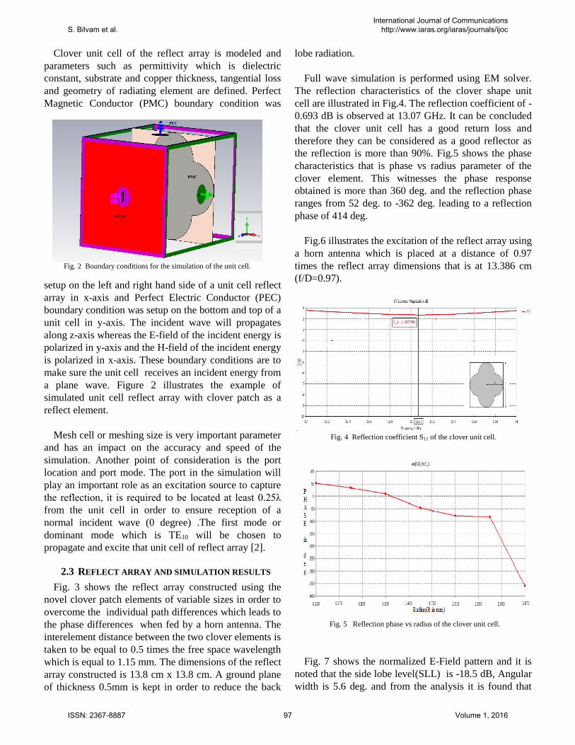
Clover unit cell of the reflect array is modeled and
parameters such as permittivity which is dielectric
constant, substrate and copper thickness, tangential loss
and geometry of radiating element are defined. Perfect
Magnetic Conductor (PMC) boundary condition was
setup on the left and right hand side of a unit cell reflect
array in x-axis and Perfect Electric Conductor (PEC)
boundary condition was setup on the bottom and top of a
unit cell in y-axis. The incident wave will propagates
along z-axis whereas the E-field of the incident energy is
polarized in y-axis and the H-field of the incident energy
is polarized in x-axis. These boundary conditions are to
make sure the unit cell receives an incident energy from
a plane wave. Figure 2 illustrates the example of
simulated unit cell reflect array with clover patch as a
reflect element.
Mesh cell or meshing size is very important parameter
and has an impact on the accuracy and speed of the
simulation. Another point of consideration is the port
location and port mode. The port in the simulation will
play an important role as an excitation source to capture
the reflection, it is required to be located at least 0.25λ
from the unit cell in order to ensure reception of a
normal incident wave (0 degree) .The first mode or
dominant mode which is TE10 will be chosen to
propagate and excite that unit cell of reflect array [2].
2.3 REFLECT ARRAY AND SIMULATION RESULTS
Fig. 3 shows the reflect array constructed using the
novel clover patch elements of variable sizes in order to
overcome the individual path differences which leads to
the phase differences when fed by a horn antenna. The
interelement distance between the two clover elements is
taken to be equal to 0.5 times the free space wavelength
which is equal to 1.15 mm. The dimensions of the reflect
array constructed is 13.8 cm x 13.8 cm. A ground plane
of thickness 0.5mm is kept in order to reduce the back
lobe radiation.
Full wave simulation is performed using EM solver.
The reflection characteristics of the clover shape unit
cell are illustrated in Fig.4. The reflection coefficient of -
0.693 dB is observed at 13.07 GHz. It can be concluded
that the clover unit cell has a good return loss and
therefore they can be considered as a good reflector as
the reflection is more than 90%. Fig.5 shows the phase
characteristics that is phase vs radius parameter of the
clover element. This witnesses the phase response
obtained is more than 360 deg. and the reflection phase
ranges from 52 deg. to -362 deg. leading to a reflection
phase of 414 deg.
Fig.6 illustrates the excitation of the reflect array using
a horn antenna which is placed at a distance of 0.97
times the reflect array dimensions that is at 13.386 cm
(f/D=0.97).
Fig. 7 shows the normalized E-Field pattern and it is
noted that the side lobe level(SLL) is -18.5 dB, Angular
width is 5.6 deg. and from the analysis it is found that
Fig. 2 Boundary conditions for the simulation of the unit cell.
Fig. 4 Reflection coefficient S11 of the clover unit cell.
Fig. 5 Reflection phase vs radius of the clover unit cell.
S. Bilvam et al.International Journal of Communications
http://www.iaras.org/iaras/journals/ijoc
ISSN: 2367-8887 97 Volume 1, 2016

the directivity is 24.5 dBi and the gain is 24.03 dB.
Table 1 summarizes the characteristics and features of
the novel clover reflect array.
3. CONCLUSION
A Ku band reflect array antenna which has the
features of novel unit cell and wide phase characteristics
is discussed in this paper. From the results, investigating
the clover unit cell , it can be validated and may be
called as a good reflector for the reflect array with
reflection more than 90% and provides a wide reflection
phase greater than 410 deg. compared to the phase
obtained in [2-5] . The feed arrays show deep SLL
suppression, high gain and directivity which is suitable
for the satellite communication. Further study should
focus on improving the - 3 dB Beam width, rigidity,
reduction in the cost of the construction of the reflect
array and also the reduction of the back lobes using
frequency selective surface as proposed in [8].
V . REFERENCES
[1] J.Huang and Jose A.C ,Reflect array Antenna. IEEE
Press, New York: Wiley, 2008.
[2] Zubir, F., M. K. A. Rahim, O. B. Ayop, and H. A.
Majid, "Design and analysis of microstrip reflect
array antenna with Minkowski shape radiation
element," Progress In Electromagnetics Research B,
Vol. 24, 2010,pp 317-331.
[3] D. M. Pozar and T. A. Metzler, “Analysis of a
reflect array antenna using microstrip patches of
variable size,” Electron. Lett., vol. 29, Apr. 1993,pp.
657–658.
[4] M.G.N.Alsath ,M.Kanagasabai and S.Arunkumar,"
Dual-band dielectric resonator reflect array for c/x-
bands," IEEE Antennas and wireless Propag. lett.,
vol. 11, pp. 1253–1256,2012.
[5] D.Oloumi, S.Ebadi, A.Kordzadeh, A.Semnani,
P.Mousavi and X.Gong, "Miniaturized reflect array
unit cell using fractal-shaped patch-slot
configuration," IEEE Antennas and wireless
Propag. lett., vol. 11,2012, pp. 10–13.
[6] Ren, L.-S., Y.-C. Jiao, F. Li, J.-J. Zhao, and G.
Zhao, "A novel dual-petal loop element for
broadband reflect array," Progress In
Electromagnetics Research Letters, Vol. 20, 2011,pp
157-163.
[7] M.E.Bialkowski and K.H.Sayidmarie,"Phasing
characteristics of a single layer microstrip reflect
array employing various basic element shapes,"
IEEE Procs. iWAT,Chiba,Japan., IT42, 2012 , pp.
79–82.
[8] Ren, L.-S., Y.-C. Jiao, J.-J. Zhao and F.Li, "RCS
Reduction for a FSS-Backed Reflect array using a
ring element," Progress In Electromagnetics
Research Letters, Vol. 26, 2011.,pp 115-123.
[9] K.H.Sayidmarie and M.E.Bialkowski ,"Fractal unit
cells of increased phasing range and low slopes for
single layer microstrip reflect arrays," IET Microw.
Antennas Propag.., vol. 5,Iss.11, 2011, pp. 1371–
1379.
Fig. 6 Reflect array setup fed by horn.
Fig. 7 E-Field radiation pattern.
TABLE I PERFORMANCE OF CLOVER REFLECTARRAY
Parameters Value
Phase range ( deg. ) 414
Gain (dB) 24.03 Side lobe level (SLL) < -18.5 dB
-3 dB beam width ( deg. ) 5.6
E field ( dBV/m ) 39.14
S. Bilvam et al.International Journal of Communications
http://www.iaras.org/iaras/journals/ijoc
ISSN: 2367-8887 98 Volume 1, 2016