Novel Imaging Radar Technology for Detection of … · ORIGINAL ARTICLE Novel Imaging Radar...
15
ORIGINAL ARTICLE Novel Imaging Radar Technology for Detection of Landmines and Other Unexploded Ordnance Markus Peichl 1 • Eric Schreiber 1 • Andreas Heinzel 1 • Stephan Dill 1 Received: 9 August 2016 / Accepted: 26 October 2016 / Published online: 7 November 2016 Ó Springer International Publishing Switzerland 2016 Abstract The safe, reliable, and efficient detection and subsequent removal of buried landmines or other unexploded ordnance (UXO) still remains a challenge. According to Landmine Monitor (2015), almost 60 states suffer the threat of antipersonnel mine contamination, while the total extent of contaminated areas is likely to be thousands of square kilometers and the total number of threat objects may be well over 100 million. In contrast, total annual clearing rates are in the order of about 230,000 landmines and about 200 km 2 for the year of 2014, as the number of new contaminations continues to grow. Although non-technical surveillance for the identification of contamination improves slowly, more progress is needed in the basic detection of UXO. Although many new technologies have been investigated the last 20 years, the classical ones like metal detectors and dogs in cooperation with humans operators are still the most commonly ones used today. Hence, the detection process for many scenarios is unacceptably slow and dangerous for the operators, as they are typically less than 1 m away from the threats. Hence, a sensor technology enabling a sufficient stand-off distance for operators and reliable detection at high area throughput is desirable. The following paper describes the physical background, the system design, and representative measurement results of our innovative radar approach to this problem. Keywords Security research Landmine detection Unexploded ordnance Synthetic aperture radar Spatial resolution Radar clutter & Markus Peichl [email protected] 1 Deutsches Zentrum fu ¨r Luft- und Raumfahrt (DLR), Institut fu ¨r Hochfrequenztechnik und Radarsysteme, Mu ¨nchener Straße 20, 82234 Weßling, Germany 123 Eur J Secur Res (2017) 2:23–37 DOI 10.1007/s41125-016-0011-3
Transcript of Novel Imaging Radar Technology for Detection of … · ORIGINAL ARTICLE Novel Imaging Radar...

ORIGINAL ARTICLE
Novel Imaging Radar Technology for Detectionof Landmines and Other Unexploded Ordnance
Markus Peichl1 • Eric Schreiber1 • Andreas Heinzel1 •
Stephan Dill1
Received: 9 August 2016 /Accepted: 26 October 2016 / Published online: 7 November 2016
� Springer International Publishing Switzerland 2016
Abstract The safe, reliable, and efficient detection and subsequent removal of
buried landmines or other unexploded ordnance (UXO) still remains a challenge.
According to Landmine Monitor (2015), almost 60 states suffer the threat of
antipersonnel mine contamination, while the total extent of contaminated areas is
likely to be thousands of square kilometers and the total number of threat objects
may be well over 100 million. In contrast, total annual clearing rates are in the order
of about 230,000 landmines and about 200 km2 for the year of 2014, as the number
of new contaminations continues to grow. Although non-technical surveillance for
the identification of contamination improves slowly, more progress is needed in the
basic detection of UXO. Although many new technologies have been investigated
the last 20 years, the classical ones like metal detectors and dogs in cooperation
with humans operators are still the most commonly ones used today. Hence, the
detection process for many scenarios is unacceptably slow and dangerous for the
operators, as they are typically less than 1 m away from the threats. Hence, a sensor
technology enabling a sufficient stand-off distance for operators and reliable
detection at high area throughput is desirable. The following paper describes the
physical background, the system design, and representative measurement results of
our innovative radar approach to this problem.
Keywords Security research � Landmine detection � Unexploded ordnance �Synthetic aperture radar � Spatial resolution � Radar clutter
& Markus Peichl
1 Deutsches Zentrum fur Luft- und Raumfahrt (DLR), Institut fur Hochfrequenztechnik und
Radarsysteme, Munchener Straße 20, 82234 Weßling, Germany
123
Eur J Secur Res (2017) 2:23–37
DOI 10.1007/s41125-016-0011-3

1 Introduction
The reliable detection of buried UXO in earth ground is a complex undertaking,
especially when the articulation of the scene to be investigated can have many
facets. There are thousands of possible target types comprising many different
materials and constructions, buried in very different types of earth and covered by
various types of vegetation or obscurants. Access also becomes an additional
problem, potentially arising due to natural or man-made activity. However, many
new and different sensing approaches have been investigated in the past 20 years,
e.g., infrared sensing of small temperature gradients, laser vibrometry using acoustic
ground stimulation, training of rats and bees for detecting explosive vapor based on
an awarding principle, electronic devices for reacting on explosive vapor by
changing electrical currents, Terahertz spectroscopy to measure typical explosive
fingerprint spectra, bacteria to become fluorescent by explosive digestion, and
ground penetrating radars (GPR) either close to ground or stand-off to detect
impedance mismatches and backscatter differences in ground, just to mention some
of those. On the other hand, the classical methods like metal detectors or prodders,
the latter being a type of fumbling rods, have been improved as well to increase
detection capabilities. Besides new sensing technologies, the use of robots and
remotely controlled vehicles as sensor platforms has been advanced to reduce risk of
the deminers. In addition, brute force methods like soil pronging tanks or plants are
available, being used predominantly for fast military clearing. Figure 1 illustrates
few of the above mentioned methods and technologies for better understanding.
Fig. 1 Photographs of various methods used for landmine and UXO detection; a manually operatedcombination of metal detector and GPR (Pica.Army 2016); b mine detection dog in action (Globalgiving2016); c GPR array carried by a military vehicle (Theleadsouthaustralia 2016); d GPS assisted robot witha sensor embedded head to detect landmines (Telovation 2016)
24 M. Peichl et al.
123
Basically, humanitarian demining and military demining have to be differenti-
ated, since the situation when and how to clean and the tolerable level of residual
risk due to remaining threats, are different. However, most methods and
technologies are similar or even identical for both cases. During the past years
of, it became evident that no technology on its own can solve the problem of safe,
reliable and efficient detection. Hence, the most suitable approach will be the use of
a multi-sensor system and a certain degree of data fusion, which could improve
reliability considerably. However, the safety and efficiency of the demining process
is not directly addressed by that. Most practiced methods today operate rather close
to the threats and in a rather punctual measurement mode, which makes demining
dangerous for the operators and provides low aerial throughput with time.
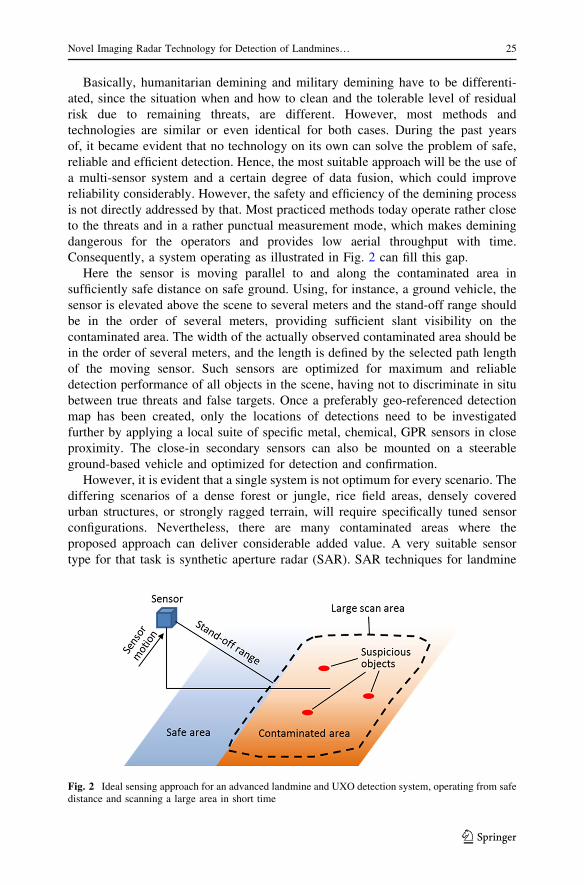
Consequently, a system operating as illustrated in Fig. 2 can fill this gap.
Here the sensor is moving parallel to and along the contaminated area in
sufficiently safe distance on safe ground. Using, for instance, a ground vehicle, the
sensor is elevated above the scene to several meters and the stand-off range should
be in the order of several meters, providing sufficient slant visibility on the
contaminated area. The width of the actually observed contaminated area should be
in the order of several meters, and the length is defined by the selected path length
of the moving sensor. Such sensors are optimized for maximum and reliable
detection performance of all objects in the scene, having not to discriminate in situ
between true threats and false targets. Once a preferably geo-referenced detection
map has been created, only the locations of detections need to be investigated
further by applying a local suite of specific metal, chemical, GPR sensors in close
proximity. The close-in secondary sensors can also be mounted on a steerable
ground-based vehicle and optimized for detection and confirmation.
However, it is evident that a single system is not optimum for every scenario. The
differing scenarios of a dense forest or jungle, rice field areas, densely covered
urban structures, or strongly ragged terrain, will require specifically tuned sensor
configurations. Nevertheless, there are many contaminated areas where the
proposed approach can deliver considerable added value. A very suitable sensor
type for that task is synthetic aperture radar (SAR). SAR techniques for landmine
Fig. 2 Ideal sensing approach for an advanced landmine and UXO detection system, operating from safedistance and scanning a large area in short time
Novel Imaging Radar Technology for Detection of Landmines… 25
123

detection have been refined over a number of years (Lawrence et al. 1999; Liu et al.
2003; Lloyd and Longstaff 2003; Feng et al. 2005; Wu et al. 2010; Kabourek et al.
2012).
2 Basics of Imaging Microwave Radar
The interaction of electromagnetic waves with matter is dictated by the electric and
magnetic properties of the material. The bulk is defined in terms of reflection,
transmission, and absorption of incident energy. Measuring such parameters by
sensors can deliver information about an object. A suitable frequency range to
perform such observations with respect to sensor size, interaction responsivity, and
hardware availability is the microwave region. Here the interaction is purely defined
on the bulk behavior of the material, i.e., that determined by the permittivity, and
the permeability of the material. Spectral line features generally appear in the
terahertz, infrared, and optical region of the electromagnetic spectrum, but radiation
in those bands has insufficient penetration for buried UXO detection. Microwaves,
on the other hand, with their longer wavelengths have sufficient penetration in and
through many non-metallic materials, so buried objects with some reflectivity will
generate a signature. Hence in theory, even objects buried in natural soils can
interact with incident waves, thus providing information on them. The microwave
frequency range is roughly defined by 1–30 GHz, and the range of 30–300 GHz is
called the millimeter-wave range. Corresponding wavelengths are 30–1 cm and
10–1 mm. Detailed information on radar and electromagnetic waves can be found in
Ulaby (1981), (1982).
2.1 Reflection and Scattering
Any material can be characterized by its complex permittivity e and its complex
permeability l, both together defining the complex wave impedance Z:
e ¼ ðe0 þ je00Þe0; l ¼ ðl0 þ jl00Þl0; Z ¼ffiffiffi
le
r
; j ¼ffiffiffiffiffiffiffi
�1p
ð1a� cÞ
e0 � 8:854� 10�12 As
Vm; l0 � 1:257� 10�6 Vs
Am; Z0 ¼
ffiffiffiffiffi
l0e0
r
� 377 ð2a� cÞ
The quantities e0 and e00 are real and imaginary part of the intrinsic permittivity, and
l0 and l00 are real and imaginary part of the intrinsic permeability, both being
exclusive material parameters to be in general determined by measurements. The
other quantities e0, l0 and Z0 are the permittivity, permeability and wave impedance
of vacuum or free space, being valid as well for normal atmospheric conditions of
air. Now each abrupt change of wave impedance gives rise to certain wave
reflection. For perpendicular incidence on a smooth interface between two mate-
rials, indexed by numbers 1 and 2, the field reflection coefficient is given by
26 M. Peichl et al.
123

r ¼ Z1 � Z2
Z1 þ Z2; 0� rj j � 1; ð3Þ
where permittivity, permeability and wave impedance for each material are com-
puted according to Eqs. (1a–c) and (2a–c). Note that, if material 2 is metal, the
imaginary part of the intrinsic permittivity tends towards infinity, and thus the
magnitude of the reflection coefficient approaches the value of |r| = 1, i.e., a
hundred percent reflection. Typical values for real and imaginary parts of the
intrinsic permittivity of most natural materials are e0 = 1–80 and e00 = 0–40
depending on various parameters like material composition, frequency, temperature,
etc., where the maxima are valid for pure water. Most purely dielectric and partly
transparent materials are much below the maxima in the order of up to 20 for the
real part and up to 1 for the imaginary part. Furthermore, most natural materials as
well as synthetics have no or very low magnetic features, and thus l0 = 1 and
l00 = 0 is a valid approximation.
Now the situation for a general imaging radar observing a landmine scene can be
illustrated as shown in Fig. 3. Mono-static radar, i.e., the transmitter (TX) and the
receiver (RX) are located at the identical elevated position, produces a focused beam
intersecting the ground with footprint area A. The beam is scanned in a suitable pattern
as indicated by the dashed line across the scene to produce a radar image.
Now, if the ground would be homogeneous, the surface would be completely flat,
and the beam had certain incidence angle with respect to the ground, most reflected
Fig. 3 Sketch of mono-static real-beam imaging radar scanning across a ground region. The ground hasa general wave impedance ZS, and two target areas having different impedances Z1 and Z2 are embedded.The area of the focused antenna footprint is denoted by A
Novel Imaging Radar Technology for Detection of Landmines… 27
123

energy would be fully reflected in a direction away from the radar. So no
information could be acquired. Fortunately, most natural surfaces are neither
completely flat nor do they have no roughness. These two features cause, depending
on their actual geometrical articulation that some energy is reflected back to the
radar, called radar backscatter. The amount of backscatter cannot be described
analytically due to the rather stochastic surface structure, but it is linked to the local
changes in wave impedance between air and ground within the antenna footprint
and across the whole scene. The quantity describing the backscatter of a surface,
i.e., the backward reflected radiation, now is the radar cross-section (RCS) r. TheRCS is an equivalent area in square meters, usually being not identical to the
observed footprint area, since it depends strongly on the specific structure and
material type of the surface besides other physical parameters. Note that the RCS as
well describes in the same way the backscatter of an isolated object within the
antenna beam, e.g., a sphere, a cube, or a landmine, where for many canonical
objects an analytical solution to compute the RCS exists. For natural surfaces, the
RCS usually has to be measured and is expressed as the dimensionless RCS per unit
area r0, so that the RCS of a certain area of size A can be computed by
r ¼ r0A: ð4Þ
In general, the RCS of any object or surface depends in a complicated way on target
parameters permittivity, permeability, shape and roughness, and from observation
parameters frequency, incidence angle and polarization. Polarization characterizes
the orientation of the incident electromagnetic fields with respect to the object or
ground surfaces.
Consequently, by scanning a surface as indicated in Fig. 3, surface areas or even
buried target areas can be detected by microwave radar purely based on mismatches
in wave impedance, i.e., differences in permittivity and permeability between
interfaces. However, those articulate weaker or stronger, heavily dependent also on
previously mentioned other parameters, so that a few very important constraints on
radar imaging have to be considered.
2.2 Penetration Depth
Since usually landmines and UXO are buried in the ground, it is of great importance
to know how far radar can penetrate into soil and deliver useful information. The
parameter describing quantitatively this ability is given by the penetration depth d,
d ¼ffiffiffi
e0p
= 2pe00ð Þ: ð5Þ
which is a definition based on power dissipation by a factor of 1/e2 up to depth d,
e being Euler’s constant, and k is the wavelength. Using a simple soil model to
compute the permittivity of soil (Ulaby 1992) depending on moisture content, the
penetration depth over frequency can be illustrated as shown in Fig. 4. Note that the
permittivity due to the moisture content as well has a strong dependence on fre-
quency. In summary it becomes evident that for a certain penetration capability into
soil the lower microwave region has to be used. A reasonable upper value for
28 M. Peichl et al.
123

instance is 3 GHz to achieve in most moisture conditions at least few centimeters of
penetration. However, it should be emphasized that Eq. (5) is only a definition.
Hence, the radar for buried object detection does not necessarily fail at larger depths
or higher frequencies.
2.3 Spatial Resolution
The objects of interest as in the case of landmines and UXO are typically not larger
than 30 cm diameter, e.g., anti-tank mines. Smallest objects like antipersonnel
mines can be as small as 5 cm diameter, below that size the threat potential of any
of such objects is too low, and the expense for resolving such targets in an image
becomes unreasonably high. Figure 5 illustrates the extremal cases of very low and
very high spatial resolution given in the size range of typical objects of interest.
It becomes evident that the spatial resolution of the imaging radar should achieve
at least the size of the smallest objects to be detected. Otherwise, as shown in the
low resolution image, targets may not be discriminated spatially from each other
and the contrast with respect to the surrounding background decreases considerably.
Fig. 4 Penetration depth ofmicrowaves in soil of differentmoisture content as a function offrequency. The yellow region isappropriate for buried objectdetection as in the case ofdemining (color figure online)
Fig. 5 Illustration of spatial resolution. The high resolution image shows three large and four smallsquare-shaped objects imaged at high spatial resolution\1 cm; the low resolution image shows the sameobjects at low spatial resolution of *20 cm; for comparison two real mines are shown in correspondingsize to given cm scales
Novel Imaging Radar Technology for Detection of Landmines… 29
123

Hence a successful detection may fail. A reasonable requirement for the spatial
resolution to be achieved by the radar was estimated to be in the order of 5–10 cm.
2.4 Backscatter of Targets and Background Clutter
As mentioned previously, natural surfaces or backgrounds as present in the situation
of landmine and UXO detection, e.g., grassland, meadows, raw soil, gravel, etc., can
provide as well significant RCS. This circumstance is highly welcome for scientific
Earth observation since it can provide information on ground characteristics like
vegetation cover or soil moisture, for instance. In contrast, in case of surface and
buried object detection, the background signatures, called clutter, can considerably
hinder proper object detection. This situation can be illustrated by an optical
counterpart as shown in Fig. 6.
In the optical image, a green ball is located on a green grass area. Although the ball
can be made of completely different material like plastics, the color of the ball and the
grass here is rather similar, so that a proper discrimination of the ball from the grass
background is hard. A similar situation can occur to radar imaging when a target is
located in a cluttered background. Figure 6 right shows average normalized RCS
values of different terrain in dependence of incidence angle for two useful frequencies
in landmine detection. Assuming now landmines or UXO as spherical and mostly
dielectric objects, their RCS levels can be approximated by metallic or dielectric
spheres of similar size. For those objects, the RCS can be computed and normalized
values around 10-3–10-4 or even lower can be obtained at those frequencies. Hence,
the signature strength of such objects is in the same order as terrain RCS in the
interesting incidence angle range of around 20–60�. This circumstance also makes
clear that lower incidence angles are not useful due to strongly increasing background
clutter, and higher incidence angles are less useful since the penetration capability
into the ground decreases, and due to longer ranges, the signal-to-noise ratio becomes
unacceptable. However, even in the useful range of incidence angles the discrim-
ination of target signatures from clutter can be a serious problem.
Fig. 6 Left photograph of a green ball located on green grass. Ball position is indicated by the whitearrow. Right normalized RCS of various terrain types for two frequencies and vertical TX and RXpolarization, based on a semi-empirical model from Ulaby (1989) (color figure online)
30 M. Peichl et al.
123

3 Philosophy and Design of the Radar System
Following previous considerations, a SAR system using multiple channels, different
polarization combinations, and operating in the UHF range was developed. Next the
main features and their main drivers are briefly outlined:
3.1 SAR Principle and Spatial Resolution
SAR is an imaging principle based on a side-looking geometry, hence the radar can
move on safe ground, while imaging the hazardous ground. Perpendicular to the linear
radar motion, i.e., across track, narrow radar pulses are used to scan the area of
interest. The delays of the pulses correspond to the range in across track direction. The
width of the pulses, i.e., the bandwidth of the used signal, determines the resolution in
time and consequently the range resolution via the knowledge of the speed of light. In
the direction of radar motion, i.e., along track, the spatial resolution is achieved by
coherently superimposing the radar echoes for a certain path length, called the
synthetic aperture. By that way a large antenna is synthesized by the radar motion,
similar to a real-aperture antenna of that size being not useful in practice due its size
and mass. The size of the image is determined by the minimum and maximum across
track distance to be scanned, and the length of the synthetic aperture.
3.2 UHF Range
Due to penetration depth constraints the frequency range should be lower than a few
GHz. To use reasonable antenna sizes, the lowest frequency should be at least in the
order of few 100 MHz.
3.3 Multiple Channels
The constraints of very limited target-to-clutter ratios to be expected for typical
landmine/UXO scenarios require methods to improve that situation. From
experience it was expected that a man-made target as a landmine typically shows
in average similar signature strengths, even when incidence angle, bistatic angle,
and aspect angle of observation are changed considerably. The required variability
of angles can be achieved by high-resolution SAR, i.e., a large range of aspect
angles for producing the synthetic aperture, and the use of multiple transmitters and
receivers located on different positions in elevation. The latter produces on one hand
different incidence angles for each TX/RX combination, and on the other hand,
different bistatic angles when the average distance to the area of interest is
sufficiently close to the radar. If furthermore the antenna arrangement for TX and
RX is made such that the antenna array produces certain length in vertical direction,
additionally vertical spatial resolution can be achieved, thus allowing a kind of
three-dimensional imaging. In contrast to man-made targets, the natural background
clutter usually is composed of multiple reflections within a resolution cell. Hence,
their coherent superposition within the resolution cell changes quickly with different
observation angles. In summary, by superposition of radar images from different
Novel Imaging Radar Technology for Detection of Landmines… 31
123

observation angles the clutter is averaging out more than the man-made objects,
producing a net gain in target-to-clutter ratio.
Following previous reasoning, the TIRAMI-SAR radar system was developed
and constructed within the TIRAMISU Project, partly funded by Framework
Programme 7 of the European Union (TIRAMISU Project 2012). A photograph of
the final system and its main technical characteristics are given in Fig. 7. The radar
was constructed using most modern radio frequency and digital electronics. Two
independent TX channels and four independent RX channels deliver eight
independent SAR images. Arbitrary signals can be generated fully digitally, e.g.,
a chirp or random waveforms, and on receive the full bandwidth is sampled for each
RX channel directly at radio frequency in time domain. Hence, the maximum
flexibility in signal processing is guaranteed and no information is lost due to analog
pre-processing. The radar is completely mounted on a small truck. The antenna
array is fixed to a rotatable boom to adjust the average incidence angle. The boom
can be additionally elevated in vertical direction by a lifter. Thus, the array can be
adjusted for optimum scene coverage and optimum RCS behavior. The single
antennas have been mounted in the shown configuration where the top and bottom
antennas are used for TX and the others for RX. This configuration has shown to be
Fig. 7 Photograph of final TIRAMI-SAR radar system; below most important technical characteristicsare given; GS/s GigaSamples per second, H horizontal V vertical polarization, indication given for TX-RX. Optical markers are used for motion compensation of antenna motion with respect to the scene
32 M. Peichl et al.
123

optimum with respect to observation angle variability and minimum cross talk
between TX and RX antennas. Polarization configurations are adjusted by rotating
single antennas manually to horizontal or vertical orientation. Hence, the different
polarization combinations for TX-RX, i.e., HH, VV, and HV, are measured one
after the other for the identical scene. The SAR processing is currently done offline
after the measurements. More information on TIRAMI-SAR and data processing is
given in Schreiber et al. (2016) and Heinzel et al. (2016).
4 Representative Measurement Results
For a proof of concept and to verify proper SAR processing and error correction
algorithms, various experiments on well-defined scenes have been carried out using a
sandbox at DLR facilities in Oberpfaffenhofen. For instance, an array of trihedral radar
reflectors was located on the surface of the sand to verify proper focusing of the SAR
processor all over the image area. A photograph of that scene and the corresponding
SAR image for superposition of all TX-RX combinations are shown in Fig. 8. In the
Fig. 8 Top photograph of an array of trihedral radar reflectors located on the surface of a sandbox. Thesandbox has a size of 12 m length and 8 m width, and it is surrounded by grassland; bottomcorresponding SAR image of that scene for superposition of all TX-RX combinations. The color bar isindicated in dB, and the image is normalized to its maximum value (color figure online)
Novel Imaging Radar Technology for Detection of Landmines… 33
123

SAR image, the radar reflectors are clearly visible as point sources showing correct
focusing all over the image. They have a relatively high normalized RCS of about 0.05
compared to the background. It should be considered that flat sand has lower clutter
level than the terrain materials shown in Fig. 6, e.g., r0 B 0.0001. Hence, the observed
reflector-to-clutter ratio can be up to 30 dB as being observed in the radar image.
However, it can be as well recognized that the adjacent grass land shows considerably
higher clutter level of up to 10 dB more than the sand area.
Next a landmine/UXO scene is discussed. Here, several typical objects have been
buried in normal soil covered by grass. That setup was provided during a
TIRAMISU measurement campaign at DOVO/SEDEE in Leuven, Belgium. A
photograph of the grass surface together with photographs of the targets and the
indications of their location is shown in Fig. 9. Figure 10 shows the single SAR
image for one TX-RX and one polarization combination. It is evident that the radar
reflectors again can be clearly identified as a focused point source, but in the buried
target area no clear discrimination of target and clutter responses can be performed.
That observation fully corresponds to the theoretical considerations outlined in
Fig. 9 Top photograph of a buried object scene. The surface is grassland on conventional soil. Indicatedare the locations of the buried targets and some trihedral radar reflectors located on the surface asreference targets; bottom photographs and positions of all targets. Additionally, names, diameter and corematerial of the buried targets are given
34 M. Peichl et al.
123

Sect. 2.4, and thus proper object detection can fail in case of methods based on
analyzing only single SAR images. Here the TIRAMI-SAR approach using
superposition of multi-static and multi-polarization information demonstrates its
power. Figure 11 now illustrates the superposition of all eight SAR images acquired
by 2 9 4 antenna combinations for HH and VV polarization combination.
Now the buried targets can be clearly discriminated from the clutter. While
targets 2 and 7 are detected for HH polarization they are not for VV polarization.
Only target 4 is missing in both images, probably due to the fact that the mine was
only simulated by an empty case for which the wall thickness is quite small
Fig. 10 SAR image of the scene described in Fig. 9 for only one TX-RX combination in HHpolarization. The focusing plane was set to -5 cm below the reference level of the surface. The dashedrectangle indicates the area where the targets have been buried
Fig. 11 Superimposed SAR images for all eight antenna combinations; left VV polarization; right HHpolarization. The image size corresponds to the rectangular area of Fig. 10 enclosed by the white dashedline
Novel Imaging Radar Technology for Detection of Landmines… 35
123

compared to the wavelengths. However, this result shows the importance and
necessity of precisely superimposing several SAR images of different observation
angles and using polarimetric information. This statement could be verified by
various other experiments showing similar results.
5 Conclusions
A novel radar approach has been developed and applied to the problem of reliable
landmine and UXO detection at high throughput of scanned area per time. This
method allows detection and localization of buried and surface objects in the
presence of background clutter, while up to now no discrimination of objects
concerning a threat or a false alarm is performed. Moreover, the philosophy of the
concept is to perform first reliable and effective detection of suspicious objects, and
then to use other sensors based on different physical principles to investigate further
those locations where detections occurred. By that way the overall system acts as a
multi-sensor system, being the only successful approach to face and solve the
problem for our opinion.
The use of radar for buried object detection is based on the measurement of bulk
material anomalies, producing mismatch of wave impedance, and thus giving rise
for wave scattering and reflections. Microwave radar thus is not sensitive to
spectroscopic properties, and thus cannot discriminate explosives from other matter
just by signature. Consequently, the multi-sensor approach as mentioned above will
do the discrimination.
The use of SAR technology provides the unique benefits of combining side-
looking geometry for operation from safe area into hazardous area, high area
throughput due to large image size, and highest spatial resolution for detection of
even small and weak objects in RCS. The problem of background clutter is solved
by applying a multi-channel system in TX and RX, providing different observation
angles for each TX-RX combination. In addition, the use of wave polarization
improves further considerably detection performance.
Although TIRAMI-SAR already performs satisfying at this stage, it offers plenty
of room for further optimization and improvements. Especially, the use of other
antenna array geometries, other waveforms, other polarization combinations, etc., is
of major interest. Furthermore, many other experiments and field trials have to be
executed to make performance assessment more reliable and informative.
Acknowledgements Funding was provided by EU Framework Programme 7 (FP7-SEC-2011-1 No.
284747).
References
Feng X et al (2005) Estimation of ground surface topography and velocity model by SARGPR and its
application to landmine detection. In: SPIE conference detection and remediation for mines and
minelike targets X, Vol. 5794
Globalgiving (2016). https://www.globalgiving.org/projects/mli-mine-detection-dogs/. Accessed 27 July
2016
36 M. Peichl et al.
123

Heinzel A et al (2016) Focusing methods for ground penetrating MIMO SAR Imaging within half-spaces
of different permittivity. In: Proceedings of 11th European conference on synthetic aperture radar
EUSAR’16, pp 842–846
Kabourek V et al (2012) Clutter reduction based on principal component analysis technique for hidden
objects detection. Radioengineering 21(1):464–470
Landmine Monitor (2015). http://www.the-monitor.org/en-gb/reports/2015/landmine-monitor-2015/
preface.aspx. Accessed 27 July 2016
Lawrence C et al (1999) Ultra-wide-band synthetic aperture radar for mine-field detection. IEEE
Antennas Propag Mag 41(1):18–33
Liu G et al (2003) SAR imaging for a forward-looking GPR system, In: SPIE conference detection and
remediation for mines and minelike targets VIII, Vol. 5089
Lloyd D, Longstaff I D (2003) Ultra-wideband multistatic SAR for the detection and location of
landmines. IEE proceedings. Online No. 20030444
Pica.Army (2016). http://www.pica.army.mil/Picatinny/products_services/products15.aspx. Accessed 27
July 2016
Schreiber E et al (2016) Challenges for operational use of ground-based high-resolution SAR for
landmines and UXO detection. In: Proceedings of 11th European conference on synthetic aperture
radar EUSAR’16, pp 834–837
Telovation (2016). http://www.telovation.com/articles/land-mine-detection-robot.html. Accessed 27 July
2016
Theleadsouthaustralia (2016). http://www.theleadsouthaustralia.com.au/industries/defence/minelab-to-
supply-us-military-with-mounted-mine-detection-system/. Accessed 27 July 2016
TIRAMISU Project (2012) Project website. http://fp7-tiramisu.eu. Accessed 27 July 2016
Ulaby FT (1981) Microwave remote sensing—active and passive. Microwave remote sensing
fundamentals and radiometry, vol I. Addison-Wesley, Reading
Ulaby FT (1982) Microwave remote sensing—active and passive. Radar remote sensing and surface and
emission theory, vol II. Addison-Wesley, Reading
Ulaby FT (1989) Handbook of radar scattering statistics for terrain. Artech House, Norwood
Ulaby FT (1992) Modelling radar backscatter from vegetation. Short course notes. DLR,
Oberpfaffenhofen
Wu H et al (2010) Motion compensation for landmine detecting vehicle-borne SAR. In: Proceedings of
IEEE 11th international radar symposium IRS’10
Novel Imaging Radar Technology for Detection of Landmines… 37
123
![Assessment of a Novel Imaging Technique for Commercial ...Ultrasonic Structural Radar (EUSR) [3] uses a phased-array approach with a round-robin ... The novel imaging algorithm is](https://static.fdocuments.in/doc/165x107/5ea3acbba6f4014da957b059/assessment-of-a-novel-imaging-technique-for-commercial-ultrasonic-structural.jpg)