
Novel Crowbar System in Doubly Fed Induction Generators
6
Novel Crowbar System in Doubly Fed Induction Generators Darío Lafferte, Milena Dias, Peter Zacharias Centre of Competence for Distributed Power Technology KDEE – University of Kassel Kassel, Germany Abstract— Nowadays, grid code requirements demand that wind energy converters (WEC) remain connected to the grid during grid faults and contribute to the voltage support, in the same way as conventional power plants. WEC which are capable of ridding through grid faults providing voltage and reactive power support are connected to the grid via electronic power converters, increas- ing the failure risk and reducing the reliability due to the negative influence of cosmic radiation on semiconductors. Doubly fed in- duction generators (DFIG) are widely used for wind power gen- eration, fulfil low voltage ride through (LVRT) requirements and need a power converter for only 30% of the rated generator ca- pacity, reducing the chip area and increasing the operation relia- bility. The crowbar protection is indispensable to avoid the dis- connection of DFIG during grid faults and the damage of the ro- tor side converter. This work analyses the crowbar operation ac- cording to the grid code requirements and presents a novel crow- bar system. Index Terms—Crowbar protection; doubly fed induction genera- tor (DFIG); low voltage ride through (LVRT); wind power inte- gration I. INTRODUCTION Wind power has become worldwide an important energy source with a growing installed capacity. The grid integration of a large amount of wind energy converters (WEC) into trans- mission systems may cause significant problems to the system stability due to the random nature of the wind and the operation characteristics of WEC. Large scale wind power connected into the transmission network (110 kV – 220 kV) increases the dif- ficulties in operation of the power system and can lead to prob- lems of voltage stability, making it more challenging to keep the line voltage within the tolerance range. If large wind parks are connected into the power system, grid faults can cause a voltage collapse because of the influence of induction ma- chines; as a result voltage stability deteriorates and network losses increase significantly [1][2]. Nowadays, grid codes demand that WEC remain connected to the grid during faults and contribute to voltage support by injecting reactive power during and after disturbances in the same way as conventional power plants [3]. Low voltage ride through (LVRT) capability in WEC implies that wind genera- tors should be connected to the grid through a power converter to operate with maximal active and reactive power control. WEC, as well as conventional power plants, are designed for long term utilization and have to comply with operation stand- ards in order to improve the reliability and reduce maintenance costs. On the other hand, cosmic rays substantially raise the fail- ure rate in power electronic devices (e.g. IGBTs) and their neg- ative effect is increased with the altitude over the sea level and the semiconductor surface size, raising the repair and mainte- nance costs [4][5]. Therefore, WEC should have a minimal pos- sible semiconductor are in the power converter, especially for wind parks located at considerable heights. WEC based on doubly fed induction generators (DFIG) un- doubtedly are one of the leading technologies for wind power. They are a cost effective, efficient and reliable solution with many advantages over other WEC systems such as less con- verter losses, decoupled control of the active and reactive power and a variable speed operation. In DFIG systems, the stator is directly connected to the grid while the rotor is connected to the grid through a back-to-back power converter, which is typically sized for 30% of the generator rating and composed of the rotor- side converter (RSC) and the grid-side converter (GSC), linked through a DC bus. A grid fault or voltage drop at the stator windings will cause high rotor over-currents because of the magnetic coupling between stator and rotor, which could dam- age the RSC. The most common method to avoid high rotor currents and the disconnection of DFIG is the use of a crowbar protection during faults, which bypasses the rotor and impedes the current flow from the rotor windings into the RSC. How- ever, during the time in which the crowbar is activated, the RSC is deactivated and WEC can neither contribute to the voltage support nor can the power output be controlled. Therefore, crowbar systems have to be improved in order to fulfil new grid code requirements and allow reactive power supply during grid faults. This work analyses the DFIG concept as well as the crowbar operation considering grid code requirements and pre- sents a novel active crowbar system. II. LOW VOLTAGE RIDE THROUGH The most important requirement regarding WEC connected to the grid under faults is the LVRT capability, which has been introduced worldwide in many grid codes in order to achieve a stable and reliable system operation, especially in grids with a This work has been sponsored by the Johannes Hübner Foundation
Transcript of Novel Crowbar System in Doubly Fed Induction Generators
Novel Crowbar System in Doubly Fed Induction Generators
Darío Lafferte, Milena Dias, Peter Zacharias Centre of Competence for Distributed Power Technology
KDEE – University of Kassel Kassel, Germany
Abstract— Nowadays, grid code requirements demand that wind energy converters (WEC) remain connected to the grid during grid faults and contribute to the voltage support, in the same way as conventional power plants. WEC which are capable of ridding through grid faults providing voltage and reactive power support are connected to the grid via electronic power converters, increas-ing the failure risk and reducing the reliability due to the negative influence of cosmic radiation on semiconductors. Doubly fed in-duction generators (DFIG) are widely used for wind power gen-eration, fulfil low voltage ride through (LVRT) requirements and need a power converter for only 30% of the rated generator ca-pacity, reducing the chip area and increasing the operation relia-bility. The crowbar protection is indispensable to avoid the dis-connection of DFIG during grid faults and the damage of the ro-tor side converter. This work analyses the crowbar operation ac-cording to the grid code requirements and presents a novel crow-bar system.
Index Terms—Crowbar protection; doubly fed induction genera-tor (DFIG); low voltage ride through (LVRT); wind power inte-gration
I. INTRODUCTION
Wind power has become worldwide an important energy source with a growing installed capacity. The grid integration of a large amount of wind energy converters (WEC) into trans-mission systems may cause significant problems to the system stability due to the random nature of the wind and the operation characteristics of WEC. Large scale wind power connected into the transmission network (110 kV – 220 kV) increases the dif-ficulties in operation of the power system and can lead to prob-lems of voltage stability, making it more challenging to keep the line voltage within the tolerance range. If large wind parks are connected into the power system, grid faults can cause a voltage collapse because of the influence of induction ma-chines; as a result voltage stability deteriorates and network losses increase significantly [1][2].
Nowadays, grid codes demand that WEC remain connected to the grid during faults and contribute to voltage support by injecting reactive power during and after disturbances in the same way as conventional power plants [3]. Low voltage ride through (LVRT) capability in WEC implies that wind genera-tors should be connected to the grid through a power converter
to operate with maximal active and reactive power control. WEC, as well as conventional power plants, are designed for long term utilization and have to comply with operation stand-ards in order to improve the reliability and reduce maintenance costs. On the other hand, cosmic rays substantially raise the fail-ure rate in power electronic devices (e.g. IGBTs) and their neg-ative effect is increased with the altitude over the sea level and the semiconductor surface size, raising the repair and mainte-nance costs [4][5]. Therefore, WEC should have a minimal pos-sible semiconductor are in the power converter, especially for wind parks located at considerable heights.
WEC based on doubly fed induction generators (DFIG) un-doubtedly are one of the leading technologies for wind power. They are a cost effective, efficient and reliable solution with many advantages over other WEC systems such as less con-verter losses, decoupled control of the active and reactive power and a variable speed operation. In DFIG systems, the stator is directly connected to the grid while the rotor is connected to the grid through a back-to-back power converter, which is typically sized for 30% of the generator rating and composed of the rotor-side converter (RSC) and the grid-side converter (GSC), linked through a DC bus. A grid fault or voltage drop at the stator windings will cause high rotor over-currents because of the magnetic coupling between stator and rotor, which could dam-age the RSC. The most common method to avoid high rotor currents and the disconnection of DFIG is the use of a crowbar protection during faults, which bypasses the rotor and impedes the current flow from the rotor windings into the RSC. How-ever, during the time in which the crowbar is activated, the RSC is deactivated and WEC can neither contribute to the voltage support nor can the power output be controlled. Therefore, crowbar systems have to be improved in order to fulfil new grid code requirements and allow reactive power supply during grid faults. This work analyses the DFIG concept as well as the crowbar operation considering grid code requirements and pre-sents a novel active crowbar system.
II. LOW VOLTAGE RIDE THROUGH
The most important requirement regarding WEC connected to the grid under faults is the LVRT capability, which has been introduced worldwide in many grid codes in order to achieve a stable and reliable system operation, especially in grids with a
This work has been sponsored by the Johannes Hübner Foundation
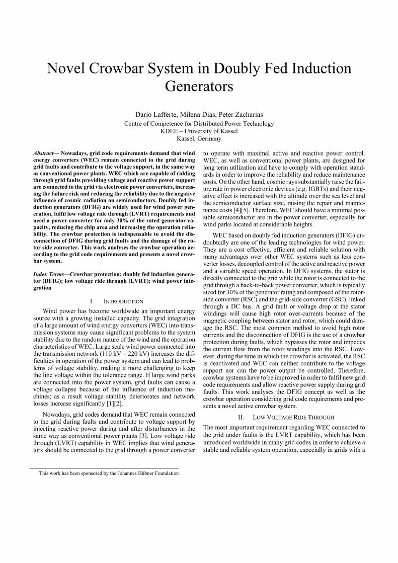
large proportion of wind power. Before the LVRT inclusion, wind generators were allowed to disconnect from the grid in case of voltage drops caused by grid faults. Nevertheless, the disconnection of large amount of WEC in a power system with high wind power penetration levels can lead to voltage collapse and stability problems. This additional loss of power genera-tion as a result of the disconnection can also cause a greater generation-consumption imbalance [6]. Therefore, WEC have to remain connected to the grid and provide voltage support during and after faults. They must withstand voltage dips of a certain percentage of the nominal voltage for a specified time duration. Fig. 1 shows the LVRT requirements of the German, Spanish and Chilean grid codes.
Fig. 1 LVRT requirements in Germany, Chile and Spain
III. WIND ENERGY CONVERTERS BASED ON DFIG
A. Doubly Fed Induction Generator
Many authors have described the modelling of WEC based on doubly fed induction generators [7][8][9]. Therefore, this work merely presents the main issues of DFIG. The typical con-figuration is presented in Fig. 2.
Fig. 2 DFIG-based WEC system
This concept uses a wound rotor induction generator with slip-rings to transmit current between the rotor and the power converter. The converter is a back-to-back PWM IGBT-based converter, which is composed of the RSC, the GSC and a DC bus (DC-link). Variable speed operation is obtained by inject-ing a controllable voltage into the rotor at the desired slip fre-quency. The PWM converter allows variable speed operation of the wind turbine by decoupling the rotor mechanical speed from the synchronous grid frequency, thereby enabling DFIG
under normal operation conditions to operate at optimal rotor speed thus maximizing the power generation. The RSC regu-lates the active and reactive power injected by the DFIG into the grid while the GSC regulates the DC-link voltage and the power transferred to the grid via the rotor.
B. Mathematical Model
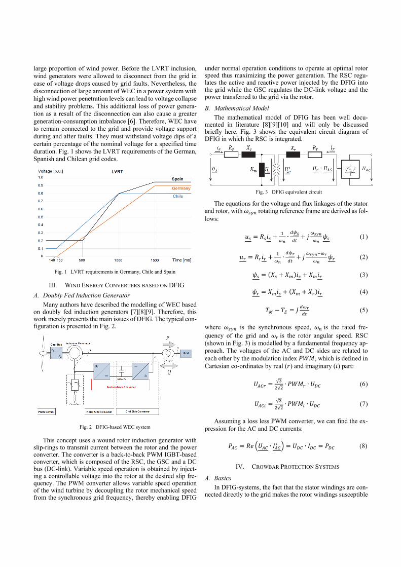
The mathematical model of DFIG has been well docu-mented in literature [8][9][10] and will only be discussed briefly here. Fig. 3 shows the equivalent circuit diagram of DFIG in which the RSC is integrated.
The equations for the voltage and flux linkages of the stator and rotor, with rotating reference frame are derived as fol-lows:
∙
∙
where is the synchronous speed, is the rated fre-quency of the grid and is the rotor angular speed. RSC (shown in Fig. 3) is modelled by a fundamental frequency ap-proach. The voltages of the AC and DC sides are related to each other by the modulation index , which is defined in Cartesian co-ordinates by real ( ) and imaginary ( ) part:
√
√∙ ∙
√
√∙ ∙
Assuming a loss less PWM converter, we can find the ex-pression for the AC and DC currents:
∙ ∗ ∙ (8)
IV. CROWBAR PROTECTION SYSTEMS
A. Basics
In DFIG-systems, the fact that the stator windings are con-nected directly to the grid makes the rotor windings susceptible
Fig. 3 DFIG equivalent circuit

to high over-currents induced during grid faults, which can damage the sensitive RSC. If the induced rotor voltage is higher than the DC-link voltage, the rotor currents are no longer con-trollable. The most common method to avoid high induced ro-tor currents or an over-voltage in the DC-link during grid volt-age dips is the use of a crowbar protection at the rotor terminals. While the crowbar is activated, it provides a safe route for the rotor over-currents by bypassing the rotor. The RSC is disabled and the DFIG-system behaves as a conventional squirrel cage induction generator with a higher rotor resistance expanding the critical rotor speed during the disconnection of the RSC from the rotor windings [11]; the generator control is lost and no grid support is possible. The magnetization of the machine that was provided by the RSC under steady-state conditions is lost and the generator absorbs a large amount of reactive power from the stator and thus from the network [12], which can further reduce the voltage at the generator terminals. Such behaviour is not al-lowed in actual grid codes. Although the use of the crowbar system avoids the disconnection of DFIG-based WEC from the grid and protects the RSC against rotor over-currents during faults (as expected), while the crowbar is activated, there is no power control and the RSC is disabled. Therefore and in order to provide LVRT capability, the crowbar short circuit has to be eliminated without disconnecting the turbine from the grid [8].
For that reason it is necessary the use of “active crowbars” in order to have a controllable activation and deactivation of the protection. To allow LVRT, it is important to minimize the by-pass time in which the crowbar is activated and the RSC is switched off. If the crowbar only operates long enough to re-duce the induced over-currents, e.g. for several milliseconds, it is possible to achieve a quasi-continuous reactive power sup-port. If we consider that the GSC is not directly coupled to the rotor windings, this converter does not have to be disabled and can therefore be used as a STATCOM to produce reactive power during faults but limited by its rating [13]. Independently of implementation of the crowbar system, this can be repre-sented as a crowbar equivalent resistance at the rotor terminals whose value has further consequences. A high crowbar re-sistance value should lead with ⁄ to a short decay time constant reducing the “dead time” in which the generator can-not be controlled. However, a high resistance could also lead to a high rotor voltage exceeding the DC-link voltage. In this case, the rotor current will flow across the RSC via its freewheeling diodes even if it is inactive. If the crowbar resistance value is too small, the short-circuit current could be high and the elec-tromagnetic torque will have a large peak. Therefore, the equiv-alent resistance of the crowbar system has to be designed for the worst case (maximal rotor over-current) on the one hand and for a fast response time on the other hand. Moreover, the limi-tation of the maximum line-to-line rotor voltage at very large over-currents and the minimizing of the crowbar clearance time are decisive. Considering that the rotor voltage cannot exceed the DC-link voltage, we obtain [8]:
ˆ3
DCr
UU ü (9)
where is the peak value of the rotor voltage, is the DC-link voltage and ü is the turns ratio. Fig. 4 shows a DFIG equiv-alent circuit with inserted crowbar.
Fig. 4 DFIG equivalent circuit with inserted crowbar
In Fig. 4, represents the equivalent crowbar resistance. The following expression shows the rotor voltage under faults with crowbar insertion.
0 ∙
B. The Novel Crowbar
This work presents a novel crowbar system to improve the DFIG operation during grid faults. The novel crowbar’s aim is to minimize the time without regulated power supply while maximizing the potentially available current to achieve grid support during faults. The following subtasks describe the es-sential principles of the novel crowbar:
If a high short-circuit current is detected, a forced commu-tation of this current from the RSC to another robust device is required, which have to be capable of absorbing a rela-tively high energy at very high currents. Therefore, the crowbar must have a low impedance and fast and robust switches.
The stored energy in the machine must be able to dissi-pate/store towards a large voltage to ensure the shortest pos-sible dissipation phase.
The initial states of the devices and the commutations must be controlled
These basic ideas are graphically depicted as a solution scheme in Fig. 5.
Fig. 5 Schematic diagram of the novel active crowbar system
Controller
DC-Link
Back-to-Back Converter
controlled rectifier
bidirectional DC/DC converter
RSC GSC
Chopper
C1
C2
to the rotor to the grid

If an anomalous situation is detected (rotor over-currents, DC-link over-voltage or low stator voltage, which may be dan-gerous for the RSC), the proposed crowbar system switches on the controlled rectifier and this commutes the rotor current from the AC terminals of the RSC to the input of the controlled rectifier and afterwards in the capacitor C2. A rise in the volt-age of C2 leads to a reduction of the rotor over-current. This occurs reliably when the voltage is less than the voltage
. To ensure this initial state, C1 and C2 are interconnected with a DC/DC converter, which sets the voltage to a value below . By switching the controlled rectifier, the 3-phase current will be rectified and fed into C2, charging the capacitor and increasing its voltage. The initial state is restored by the DC/DC converter, which transports the additional absorbed energy in C2 into the DC-link. If the capacitor C2 is large enough in comparison to the energy to be absorbed when C2 is charging and it fulfils the condition “ ”, then the en-ergy transfer occurs slowly and with low power. Therefore, the additionally installed semiconductor area can remain small. For very large power (to be absorbed), the capacitor C2 should be complemented by a parallel breaking chopper, which switches the energy flow from the rotor into a resistor, where the additional energy is converted to heat. This ensures that the voltage and the size of C2 can be limited. An extension of the novel crowbar solution for a large rotor energy is the addi-tional parallel connection of a chopper device for the DC-link.
V. SIMULATION ANALYSIS
A. Wind energy converters in grid operation
To analyse the grid operation of WEC during faults and the effects of the crowbar parameters, a DFIG-based wind park connected to an existing power system has been simulated for the worst case (i.e. under three phase short circuits, which cause the highest short circuit currents) in DIgSILENT Pow-erFactory. The chosen power system is the Northern Intercon-nected Power System of Chile. The DFIG model was modified to improve the crowbar operation during faults by minimizing the bypass time, in which the crowbar is active and the RSC is disabled. Independently of the crowbar system, this can be rep-resented as an equivalent resistance at the rotor terminals. Therefore, the influence of this equivalent crowbar resistance was also analysed. In order to consider grid code requirements for LVRT, the DFIG model was configured to achieve a resid-ual voltage at the stator terminals by injecting reactive current during faults acc. to the Chilean grid code. The fault clearance time was set at 120 ms and the maximal rotor current for crow-bar insertion at 1.9 p.u. The crowbar is triggered when the rotor current exceeds the maximal current value.
Fig. 6 and 7 show the rotor current and the line-to-ground voltage at the terminals of two DFIG (G1 and G2) during a three short circuit at PCC. G1 represents a generator whose crowbar has a long bypass time, while G2 represents a DFIG with a reduced crowbar bypass time. G1 can only provide re-active current for a short time when the short circuit is ending. Although G1 remains connected to the grid, it does not fulfil LVRT requirements (see fig. 1). The crowbar activation of G2 reduces the short circuit over-currents in the rotor windings,
but once the rotor currents achieve an admissible operation value, the RSC will be reconnected and starts injecting reactive current. This injected current during the short circuit produces a voltage rise at the generator terminals (shown in Fig. 7) as required by the grid code. The reduced operation time of the crowbar in G2 allows reactive current support during the entire duration of the short circuit, considering that the GSC works as STATCOM during the brief time in which the crowbar is triggered and the RSC is disabled. Once the crowbar of G2 is switched off and the RSC is re-enabled, this leads to voltage support.
Fig. 6 Rotor currents for G1 and G2 in grid operation and under a three phase short circuit
Fig. 7 Line-to-ground voltage at the terminals of G1 and G2
The influence of the crowbar equivalent resistance value was also simulated under faults in grid operation. Fig. 8 shows the rotor current of G2 for different values of the crowbar re-sistance during a three phase short circuit at PCC.
The higher the crowbar resistance value, the faster the rotor short circuit currents fall. On the other hand, a too large value means that the generator requires a longer time in order to in-ject reactive current during faults. Moreover, a too large crow-bar resistance value can also increase the rotor voltage so that the rotor current in an undesirable way commutates into the
Fig. 4 Simulations results
Fig. 8 Rotor current for different crowbar resistance values
RSC. In the simulation, the rotor current falls considerable faster when 2 . . than the base case 0.1 . .. That means that the magenta curve needs a longer time to sup-plies reactive current again. The red curve can instead support the grid during the entire short-circuit time.
B. Novel Crowbar Simulations and Experimental Testing
To demonstrate the performance of the proposed crowbar, simulations and experimental results are shown. The DFIG model and the novel crowbar was simulated in MATLAB/Simulink and tested in laboratory experiments. The base values used are: 400 and 10 (acc. to our test equipment). The parameter and nominal values of DFIG used in the simulation and the experimental testing are given in the tables below.
DFIG-Nominal values
Rated Power nS
10kVA
Rated Current In 15A Rated Voltage
,rms l lU 400V
Frequency f 50Hz
Number of pole pairs pn
2
Winding ratio /S RN N
1,72
DFIG-Parameters
Stator Resistance Rs 0,8Ω Rotor Resistance
RR
1,0Ω
Stator leakage inductance lsL
1,0mH
Rotor leakage inductance lrL
1,0mH
Magnetizing inductance ML
100mH
DC voltage DCU
100V
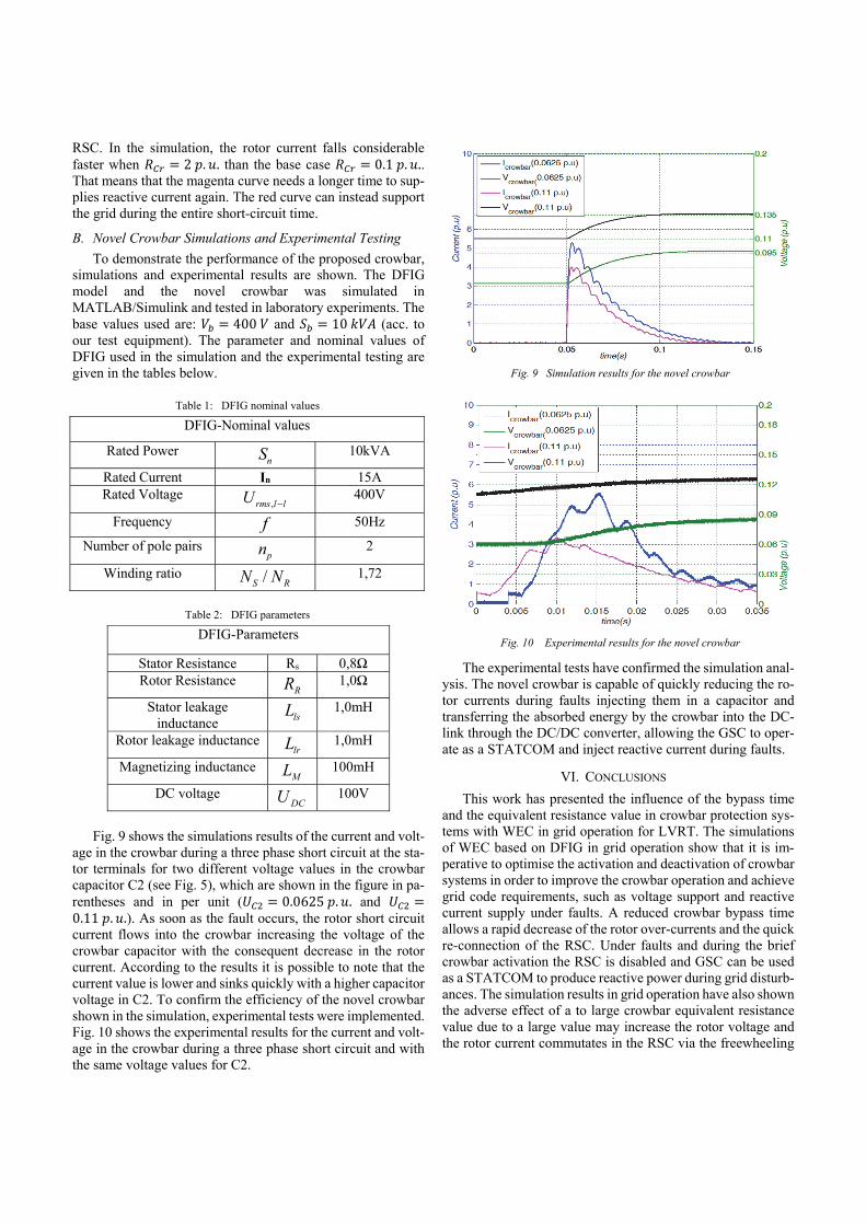
Fig. 9 shows the simulations results of the current and volt-
age in the crowbar during a three phase short circuit at the sta-tor terminals for two different voltage values in the crowbar capacitor C2 (see Fig. 5), which are shown in the figure in pa-rentheses and in per unit ( 0.0625 . . and 0.11 . .). As soon as the fault occurs, the rotor short circuit current flows into the crowbar increasing the voltage of the crowbar capacitor with the consequent decrease in the rotor current. According to the results it is possible to note that the current value is lower and sinks quickly with a higher capacitor voltage in C2. To confirm the efficiency of the novel crowbar shown in the simulation, experimental tests were implemented. Fig. 10 shows the experimental results for the current and volt-age in the crowbar during a three phase short circuit and with the same voltage values for C2.
The experimental tests have confirmed the simulation anal-ysis. The novel crowbar is capable of quickly reducing the ro-tor currents during faults injecting them in a capacitor and transferring the absorbed energy by the crowbar into the DC-link through the DC/DC converter, allowing the GSC to oper-ate as a STATCOM and inject reactive current during faults.
VI. CONCLUSIONS
This work has presented the influence of the bypass time and the equivalent resistance value in crowbar protection sys-tems with WEC in grid operation for LVRT. The simulations of WEC based on DFIG in grid operation show that it is im-perative to optimise the activation and deactivation of crowbar systems in order to improve the crowbar operation and achieve grid code requirements, such as voltage support and reactive current supply under faults. A reduced crowbar bypass time allows a rapid decrease of the rotor over-currents and the quick re-connection of the RSC. Under faults and during the brief crowbar activation the RSC is disabled and GSC can be used as a STATCOM to produce reactive power during grid disturb-ances. The simulation results in grid operation have also shown the adverse effect of a to large crowbar equivalent resistance value due to a large value may increase the rotor voltage and the rotor current commutates in the RSC via the freewheeling
Table 1: DFIG nominal values
Table 2: DFIG parameters
Fig. 9 Simulation results for the novel crowbar
Fig. 10 Experimental results for the novel crowbar

diodes even if it is inactive. Moreover, a too large crowbar re-sistance value means that the generator requires a longer time in order to inject reactive current during faults.
The novel crowbar testing has shown an innovative protec-tion system, which quickly reduces the rotor short-circuit cur-rents and protects the RSC injecting them into a capacitor. The absorbed energy is transferred to the DC-link allowing a relia-ble operation of the GSC as STATCOM to provide reactive power and voltage support during the brief time in which the crowbar is activated and the RSC is disabled. The DC/DC con-verter keeps the condition (see Fig. 5) and transfers the absorbed energy in C2 into C1 slowly and with low power, allowing that the additionally installed semiconductor area can remain small, which an important advantage is, if we consider the negative effect of cosmic rays in power electronics increas-ing the risk of failures in semiconductors, without forgetting that the back-to-back converter of DFIG-based WEC is 70% smaller than WEC alternatives with full scale converters. An-other advantage of the proposed crowbar system is the fact that the absorbed energy is not wasted by heat dissipation in a resis-tor, but it is used to keep the charge of the DC-link allowing the STATCOM operation of the GSC.
REFERENCES [1] I. Erlich, F. Shewarega, “Insert impact of large-scale wind power
generation on the dynamic behaviour of interconnected systems,” Bulk Power System Dynamics and Control – VII. Revitalizing Operational Reliability, 2007 iREP Symposium, pp. 1-7, 19-24, August 2007.
[2] H. Shien, W. Weizhou, J. Huaisen, C. Gang, W. Fujun, L. Jun, “Integration of wind farm into Gansu power grid and its operation,” International Conference on Sustainable Power Generation and Supply SUPERGEN ’09, pp. 1-5, 6-7, April 2009.
[3] C. Sourkounis, P. Tourou, “Grid Code Requirements for Wind Power Integration in Europe,” Conference Papers in Energy, vol. 2013, Article ID 437674, 9 pages, 2013.
[4] H. R. Zeller, “Cosmic ray induced failures in high power semiconductor devices, Microelectronics and Reliability,” vol. 37, issues 10-11, pp. 1711-1718, Oct. 1997.
[5] H. Kabza, H.-J. Schulze, Y. Gerstenmaier, P. Voss, J. Schmid, F. Pfirsch, K. Platzoder, “Cosmic radiation as a cause for power device failure and possible countermeasures,” 6th Int. Symposium on Power Semiconductor Devices and ICs ISPSD, 1994.
[6] I. Erlich, W. Winter, A. Dittrich, “Advanced grid requirements for the integration of wind turbines into the German transmission system,” in Proceedings of the IEEE Power Engineering Society General Meeting (PES ’06), Jun. 2006.
[7] V. Akhmatov, “Induction generators for wind power,” Multi-Science Publishing Co. Ltd., UK, 2005.
[8] G. Abad, J. López, M. Rodríguez, L. Marroyo, G. Iwanski, “Doubly fed induction machine – modeling and control for wind energy generation,” IEEE Press, John Wiley & Sons, Inc., New Jersey, 2011.
[9] M. Pöller, “Doubly fed induction machine models for stability assessment of wind farms,” in Proc. 2003 IEEE PowerTech Conference, Bologna, 2003.
[10] C. Hamon, K. Elkington, M. Ghandhari, “Doubly-fed induction generator modeling and control in DIgSILENT PowerFactory,” POWERCON 2010 – International Conference on Power System Technology, pp. 1-7, Hangzou, October 2010.
[11] A. P. Grilo, A. de Assis Mota, L. T. Moreira Mota, W. Freitas, “An analytical method for analysis of large-disurbance stability of induction generators,” IEEE Trans. on Power Systems vol. 22, pp. 1861-1869, 2007.
[12] J. Morren, S. de Haan, “Short-circuit current of wind turbines with doubly fed induction generator,” Energy Conversion, IEEE Transactios on, vol. 22, no. 1, pp. 174-180, March 2007.
[13] A. Hansen, G. Michalke, P. Sørensen, T. Lund, “Co-ordinated voltage control of DFIG wind turbines in uninterrupted operation during grid faults,” John Wiley & Sons, Wind Energy, vol. 10, issue 1, pp. 51-68, Feb. 2007.


![Investigation of Transient Models and Performances for a ... · and transient performances analysis of WTGS[3,4]. Doubly fed induction generators ... doubly fed wind turbines [5]-](https://static.fdocuments.in/doc/165x107/5abf959b7f8b9aa15e8e2fb3/investigation-of-transient-models-and-performances-for-a-transient-performances.jpg)