Novel approach to automated fingerprint recognition
7
A. Wahab S.H.Chin E. C. Ta n Indexing terms Feature extraction, Fingerprint recognition, Image processing, Structural matching Abstract: The paper describes an enhanced fingerprint recognition system consisting of image preprocessing, feature extraction and matching that runs accurately and effectively on a personal computer platform. The image preprocessing includes histogram equalisation, modification of directional codes, dynamic thresholding and ridgeline thinning which are sufficient to enhance the image to a state ready €or feature extraction. Only features extracted are stored in a file for fingerprint matching. The matching algorithm presented is a modification and improvement of the structural approach. Experimental results acquired for matching are accurate, reliable and fast for implementation using a PC and a fingerprint scanner. The proposed fingerprint recognition scheme can provide an efficient way of automated identification and can be extended to numerous other security or administration applications. 1 Introduction Because of immutability and individuality, the use of fingerprints for identification has always been of great interest to pattern recognition researchers and law enforcement people. Conventionally, fingerprint recog- nition has been conducted via either statistical or syn- tactic approaches. In the statistical approach, a fingerprint is represented by a set of n-dimensional fea- ture vector and the decision making process is deter- mined by a similarity measure such as a discriminant function. In the syntactic approach, a pattern is repre- sented as a string, tree [l] or graph [2] of fingerprint features or pattern primitives and their relations. The decision making process is then simply a syntax analy- sis or parsing process. This paper suggests the use of the statistical approach as an extension to the structural matching method proposed by Hrechali and McHugh [3] for real-time matching of fingerprint using a fingerprint scanner. Experimental results prove the effectiveness of this method in a microcomputer platform, hence mak- ing it suitable for security applications with a relative 0 IEE, 1998 I E E Proceedings online no 19981809 Paper first received 23rd June and in revised form 1st December 1997 The authors are wth the School of Applied Science, Division of Computing Systems, Nanyang Technologxal University, Nanyang Avenue, Singapole 639798, Republic of Singapore small database as compared to those in [4, 51 for large fingerprint databases. The preprocessing of fingerprint images is carried out using modified basic filtering methods which are substantially good enough for the purpose of our application with reasonable computa- tional time. 2 Image preprocessing To eliminate extraction of erroneous minutiae and con- sequently minimising the mismatch as much as possi- ble, image preprocessing is a necessary step before any feature extraction is performed. This Section describes in detail the image preprocessing techniques that were effectively applied to enhance the fingerprint images for matching. a b Fig. 1 ModiJed histogram equalisation n Original image b After modification 2.1 Histogram equalisation The method used is adopted from Pavlidis [6] and is known as modified histogram equalisation where the unwanted part of the image is made lighter so as to emphasise the desired parts. Here, as shown by Fig. 1, an input image (320 x 240 pixels) is divided into 20 x 15 small areas of 16 x 16 pixels. For each small area the transform function of each histogram equalisation is derived from the extended area of 32 x 32 pixels enclosing the small area, thus solving the problem of having grey-level discontinuities at the border of small areas. Let the input and the output level for an arbi- trary pixel be i and I, respectively. Then the accumula- tion of histogram from 0 to i (0 5 i 5 255, 0 I k s 255) is given by 7, k=O where H(k) is the number of pixels with grey level k, i.e. histogram of an area, and C(i) is also known as the cumulative frequency. The histogram equalisation IEE Proc -Vis Image Signal Process, Vol 145 No 3 June I998 160
Transcript of Novel approach to automated fingerprint recognition
A. Wahab S.H.Chin E. C. Ta n
Indexing terms Feature extraction, Fingerprint recognition, Image processing, Structural matching
Abstract: The paper describes an enhanced fingerprint recognition system consisting of image preprocessing, feature extraction and matching that runs accurately and effectively on a personal computer platform. The image preprocessing includes histogram equalisation, modification of directional codes, dynamic thresholding and ridgeline thinning which are sufficient to enhance the image to a state ready €or feature extraction. Only features extracted are stored in a file for fingerprint matching. The matching algorithm presented is a modification and improvement of the structural approach. Experimental results acquired for matching are accurate, reliable and fast for implementation using a PC and a fingerprint scanner. The proposed fingerprint recognition scheme can provide an efficient way of automated identification and can be extended to numerous other security or administration applications.
1 Introduction
Because of immutability and individuality, the use of fingerprints for identification has always been of great interest to pattern recognition researchers and law enforcement people. Conventionally, fingerprint recog- nition has been conducted via either statistical or syn- tactic approaches. In the statistical approach, a fingerprint is represented by a set of n-dimensional fea- ture vector and the decision making process is deter- mined by a similarity measure such as a discriminant function. In the syntactic approach, a pattern is repre- sented as a string, tree [l] or graph [2] of fingerprint features or pattern primitives and their relations. The decision making process is then simply a syntax analy- sis or parsing process.
This paper suggests the use of the statistical approach as an extension to the structural matching method proposed by Hrechali and McHugh [3] for real-time matching of fingerprint using a fingerprint scanner. Experimental results prove the effectiveness of this method in a microcomputer platform, hence mak- ing it suitable for security applications with a relative 0 IEE, 1998 IEE Proceedings online no 19981809 Paper first received 23rd June and in revised form 1st December 1997 The authors are wth the School of Applied Science, Division of Computing Systems, Nanyang Technologxal University, Nanyang Avenue, Singapole 639798, Republic of Singapore
small database as compared to those in [4, 51 for large fingerprint databases. The preprocessing of fingerprint images is carried out using modified basic filtering methods which are substantially good enough for the purpose of our application with reasonable computa- tional time.
2 Image preprocessing
To eliminate extraction of erroneous minutiae and con- sequently minimising the mismatch as much as possi- ble, image preprocessing is a necessary step before any feature extraction is performed. This Section describes in detail the image preprocessing techniques that were effectively applied to enhance the fingerprint images for matching.
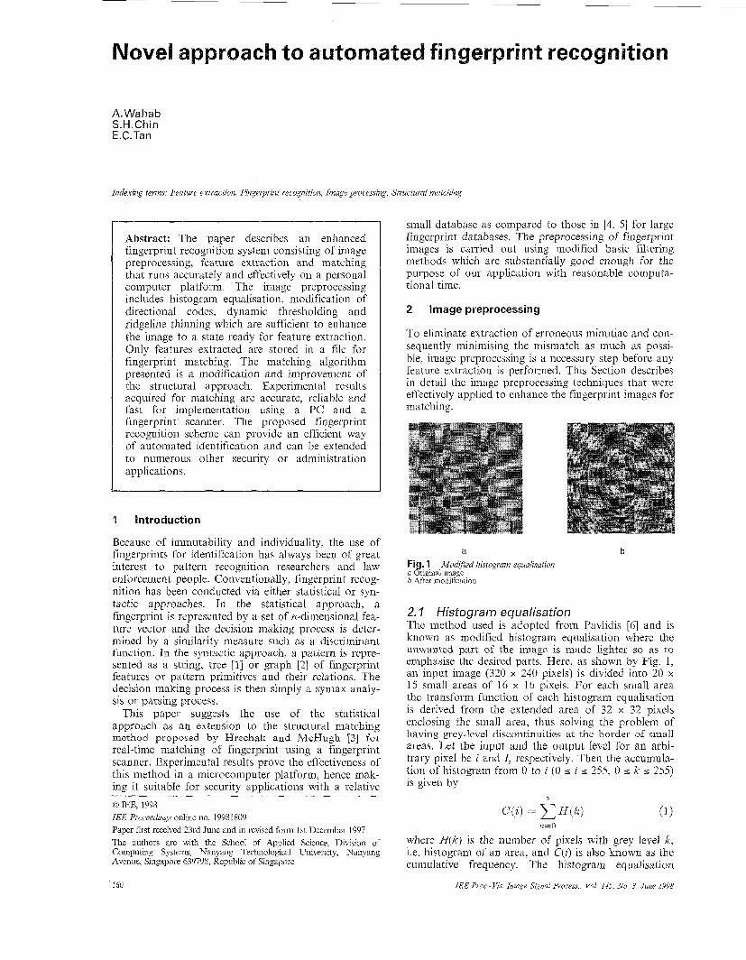
a b Fig. 1 ModiJed histogram equalisation n Original image b After modification
2.1 Histogram equalisation The method used is adopted from Pavlidis [6] and is known as modified histogram equalisation where the unwanted part of the image is made lighter so as to emphasise the desired parts. Here, as shown by Fig. 1, an input image (320 x 240 pixels) is divided into 20 x 15 small areas of 16 x 16 pixels. For each small area the transform function of each histogram equalisation is derived from the extended area of 32 x 32 pixels enclosing the small area, thus solving the problem of having grey-level discontinuities at the border of small areas. Let the input and the output level for an arbi- trary pixel be i and I , respectively. Then the accumula- tion of histogram from 0 to i (0 5 i 5 255, 0 I k s 255) is given by
7,
k=O
where H(k) is the number of pixels with grey level k, i.e. histogram of an area, and C(i) is also known as the cumulative frequency. The histogram equalisation
IEE Proc -Vis Image Signal Process, Vol 145 No 3 June I998 160

replaces i with I M N
I = C( i ) x -
where A4 is the maximum grey level allocated (255) and N is the number of pixels (16 x 16).
2.2 Extraction and modification of ridge direction Owing to the nature of fingerprints, scars are inevita- ble. This can cause the introduction of unnecessary false minutiae in the feature extraction process. To pre- vent this the directional information of ridges is obtained and modified. The directional image is a transformed version of a fingerprint image that repre- sents the local orientation of the ridges. The procedures to obtain the directional image use many of the well- known ideas proposed in earlier studies [4, 7, 81. In our approach we first divide the original image (320 x 240) into 40 x 30 small areas each containing 8 x 8 pixels. Next, each area is assigned a directional code to repre- sent the direction of the ridgeline in that area. To reduce computational time, a total of eight directional codes is used. The eight directional windows wd (d = 0, 1, 2, ..., 7), each having a length of 16 pixels are shown in Fig. 2. To find the ridge direction of a given area, each of the directional windows, wd is moved in the direction tangential to the direction of the window. Since each small area is 8 x 8 pixels, each of the direc- tional windows will have to move eight times to cover the entire area. At each location when the window moves, the mean value M( Wd) of the grey level of the pixels in the window is calculated. The fluctuation of M(Wd) is expected to be the largest when the move- ment of the directional window is orthogonal to the direction of the ridges. Therefore this area will be assigned to have ridges in the direction d such that the fluctuation of M( Wd) is the largest.
141 [51 Fig. 2 Eight directional windows [ ] indicates directional code
[El [71 W, for extraction of ridge direction
Because of the presence of noise and scars in a fin- gerprint image, some areas in the directional image will contain incorrect directional codes. Therefore the direc- tional codes in these areas need to be modified by referring to the direction of its neighbouring areas. This is achieved by calculating the directional histogram N(9 of an area and its eight neighbouring areas. Note that N ( 9 is the number of areas with directional code d. The largest value in N(d) is defined as D,, and the second largest value D2. The variable D(x, y ) is the modified directional code of the area (x, y) . The criteria to modify the directional code of an area are given by (i) D(x, y ) = D1, if 5 I N(D1) I 8 (ii) D(x, y ) = L(Dl + D2)/2J, if 3 I N(DJ I 5 and 2 I N(Dz) I N(DJ and \Dl - D,I I 2 (iii) D(x, y ) = D(x, y ) otherwise.
IEE Proc.-Vis. Image Signal Process., Vol. 145, No. 3, June 1998
The image is then reconstructed by moving the selected directional window through the central area and replacing the pixels with that of the directional win- dow. In every position of the shift, the pixels will only be added if a continuation of the ridge line is detected by comparing the pixels of the directional window with those of the neighbouring areas. Otherwise it will remain as an empty space signifying the gap between the ridge lines. The effect of modifying the directional codes is shown in Fig. 3b.
a b
C
Fig. 3 a Before enhancement b After modification of directional ccsdes c After dynamic thresholding
Modijkation of directional codes and dynamic thresholding
2.3 Dynamic th res holding Dynamic thresholding is simply the mapping of all data points having grey level more than the average grey level in a 16 x 16 sampling square to 255 (white) and all others to 0 (black). Thle result of a dynamic thresh- olding of a fingerprint ima.ge is shown in Fig. 3c.
2.4 Ridgeline thinning Before the features can be extracted, the fingerprints have to be thinned or skeletonised so that all the ridges are one pixel thick. In most of the existing thinning algorithms, when a pixel is decided as a boundary pixel, it is either deleted directly from the image [9-111 or flagged and not deleted until the entire image has been scanned [12, 131. There are deficiencies in both cases. In the former, deletion of each boundary pixel will change the object in the image and hence affect the final skeleton. This kind of algorithm does not thin the object symmetrically. To overcome this problem, some thinning algorithms use several passes in one thinning iteration. Each pass is an operation to remove bound- ary pixels from a given direction. Pavlidis [6] and Fiegin and Ben-Yosef [ 141 have developed effective algorithms using this method. However, both the time complexity and memory requirement will increase. In the latter, as the pixels are only flagged, the state of the bitmap at the end of the last iteration will be used when deciding which pixel to delete. However, if this flag map is not used to decide whether a current pixel is to be deleted, the information generated from processing the previous pixels in the current iteration
161
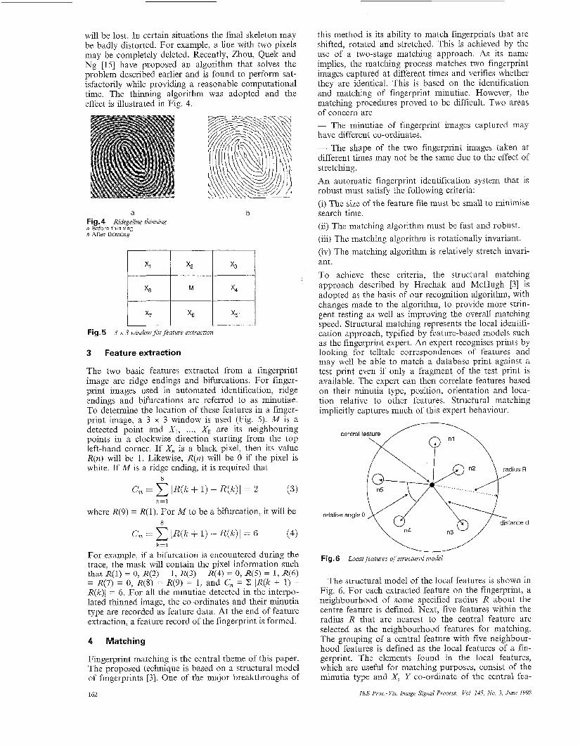
will be lost. In certain situations the final skeleton may be badly distorted. For example, a line with two pixels may be completely deleted. Recently, Zhou, Quek and Ng [15] have proposed an algorithm that solves the problem described earlier and is found to perform sat- isfactorily while providing a reasonable commtational time. The thinning algorithm effect is illustrated in Fig. 4.
a Fig. 4 Ridegeline thinning a Before thinning b After thinning
was adopted and the
b
Fig. 5 3 x 3 window fovjkature extraction
3 Feature extraction
The two basic features extracted from a fingerprint image are ridge endings and bifurcations. For finger- print images used in automated identification, ridge endings and bifurcations are referred to as minutiae. To determine the location of these features in a finger- print image, a 3 x 3 window is used (Fig. 5). M is a detected point and XI, ..., X , are its neighbouring points in a clockwise direction starting from the top left-hand corner. If Xn is a black pixel, then its value R(n) will be 1. Likewise, R(n) will be 0 if the pixel is white. If M is a ridge ending, it is required that
8
c, = IR(k + 1) - R ( k ) l = 2 ( 3 ) k=l
where R(9) = R(1). For M to be a bifurcation, it will be
C, = IR(k + 1) - R(k ) I = 6 (4)
For example, if a bifurcation is encountered during the trace, the mask will contain the pixel information such that R(l) = 0, R(2) = 1, R(3) = R(4) = 0, R(5) = 1, R(6) = R(7) = 0, R(8) = R(9) = 1, and Cn = C lR(k + 1) - R(k)j = 6. For all the minutiae detected in the interpo- lated thinned image, the co-ordinates and their minutia type are recorded as feature data. At the end of feature extraction, a feature record of the fingerprint is formed.
8
k=l
4 Matching
Fingerprint matching is the central theme of this paper. The proposed technique is based on a structural model of fingerprints [3]. One of the major breakthroughs of
162
this method is its ability to match fingerprints that are shifted, rotated and stretched. This is achieved by the use of a two-stage matching approach. As its name implies, the matching process matches two fingerprint images captured at different times and verifies whether they are identical. This is based on the identification and matching of fingerprint minutiae. However, the matching procedures proved to be difficult. Two areas of concern are - The minutiae of fingerprint images captured may have different co-ordinates. - The shape of the two fingerprint images taken at different times may not be the same due to the effect of stretching. An automatic fingerprint identification system that is robust must satisfy the following criteria: (i) The size of the feature file must be small to minimise search time. (ii) The matching algorithm must be fast and robust. (iii) The matching algorithm is rotationally invariant. (iv) The matching algorithm is relatively stretch invari- ant. To achieve these criteria, the structural matching approach described by Hrechak and McHugh [3] is adopted as the basis of our recognition algorithm, with changes made to the algorithm, to provide more strin- gent testing as well as improving the overall matching speed. Structural matching represents the local identifi- cation approach, typified by feature-based models such as the fingerprint expert. An expert recognises prints by looking for telltale correspondences of features and may well be able to match a database print against a test print even if only a fragment of the test print is available. The expert can then correlate features based on their minutia type, position, orientation and loca- tion relative to other features. Structural matching implicitly captures much of this expert behaviour.
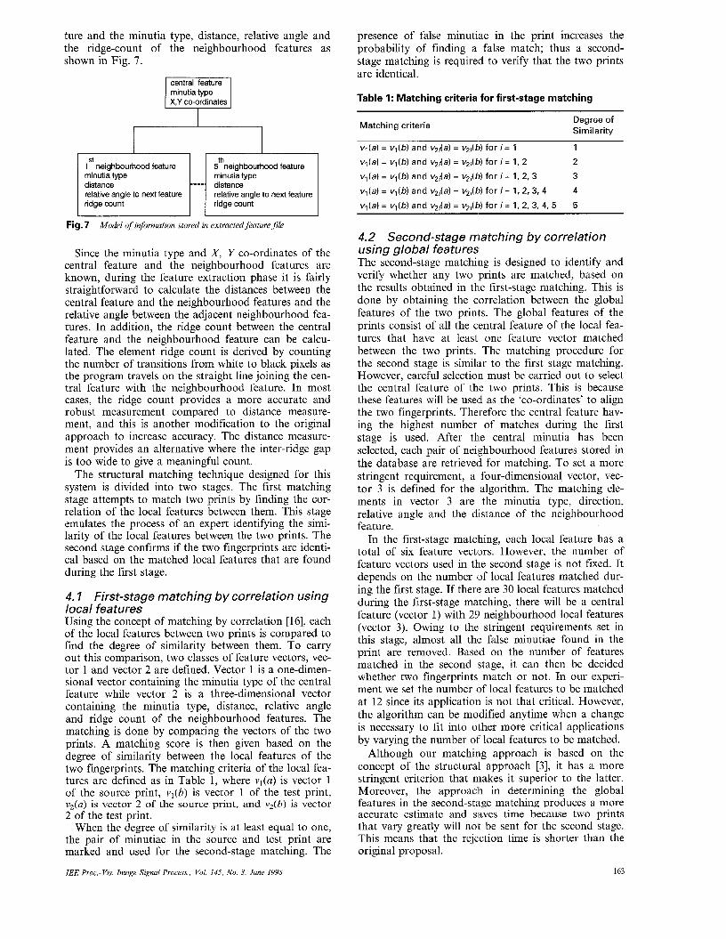
Fig.6 Local features of structural model
The structural model of the local features is shown in Fig. 6. For each extracted feature on the fingerprint, a neighbourhood of some specified radius R about the centre feature is defined. Next, five features within the radius R that are nearest to the central feature are selected as the neighbourhood features for matching. The grouping of a central feature with five neighbour- hood features is defined as the local features of a fin- gerprint. The elements found in the local features, which are useful for matching purposes, consist of the minutia type and X, Y co-ordinate of the central fea-
IEE Proc.-Vis. Image Signal Process., Vol. 145, No. 3, June 1998
ture and the minutia type, distance, relative angle and the ridge-count of the neighbourhood features as shown in Fig. 7.
minutia type X,Y co-ordinates
presence of false minutiae in the print increases the probability of finding a false match; thus a second- stage matching is required to verify that the two prints are identical.
Table 1: Matching criteria for first-stage matching
II 5 neighbourhood feature minutia type distance relative angle to next feature relative angle to next feature
ridge count ridge count
Fig. 7 Model of information stored in extructedfiatwe file
Since the minutia type and X , Y co-ordinates of the central feature and the neighbourhood features are known, during the feature extraction phase it is fairly straightforward to calculate the distances between the central feature and the neighbourhood features and the relative angle between the adjacent neighbourhood fea- tures. In addition, the ridge count between the central feature and the neighbourhood feature can be calcu- lated. The element ridge count is derived by counting the number of transitions from white to black pixels as the program travels on the straight line joining the cen- tral feature with the neighbourhood feature. In most cases, the ridge count provides a more accurate and robust measurement compared to distance measure- ment, and this is another modification to the original approach to increase accuracy. The distance measure- ment provides an alternative where the inter-ridge gap is too wide to give a meaningful count.
The structural matching technique designed for this system is divided into two stages. The first matching stage attempts to match two prints by finding the cor- relation of the local features between them. This stage emulates the process of an expert identifying the simi- larity of the local features between the two prints. The second stage confirms if the two fingerprints are identi- cal based on the matched local features that are found during the first stage.
4, I First-stage matching by correlation using local features Using the concept of matching by correlation [16], each of the local features between two prints is compared to find the degree of similarity between them. To carry out this comparison, two classes of feature vectors, vec- tor 1 and vector 2 are defined. Vector 1 is a one-dimen- sional vector containing the minutia type of the central feature while vector 2 is a three-dimensional vector containing the minutia type, distance, relative angle and ridge count of the neighbourhood features. The matching is done by comparing the vectors of the two prints. A matching score is then given based on the degree of similarity between the local features of the two fingerprints. The matching criteria of the local fea- tures are defined as in Table 1, where vl(a) is vector 1 of the source print, v,(b) is vector 1 of the test print, v2(a) is vector 2 of the source print, and vZ(b) is vector 2 of the test print.
When the degree of similarity is at least equal to one, the pair of minutiae in the source and test print are marked and used for the second-stage matching. The
IEE Psoc.-Vis. Image Signal Psocess., Vol. 145, No. 3, June 1998
Matching criteria Degree of Similarity
v,(a) = vl (b) and v2,W = v2Jb) for i = 1
v l (a ) = vl (b) and v2i(a) = v2jb) for i = 1, 2
v l ( a ) = vl (b) and v2ja) = v2Ab) for i = 1, 2, 3
1
2
3 4
5 v l (a ) = vl (b) and v2Ja) = v,;(b) for i = 1, 2, 3, 4
vl(a) = vl (b) and v2,W = v2jM for i = 1, 2, 3, 4, 5
4.2 Second-stage matching by correlation using global features The second-stage matching is designed to identify and verify whether any two prints are matched, based on the results obtained in the first-stage matching. This is done by obtaining the correlation between the global features of the two prints. The global features of the prints consist of all the central feature of the local fea- tures that have at least one feature vector matched between the two prints. The matching procedure for the second stage is similar to the first stage matching. However, careful selection must be carried out to select the central feature of the two prints. This is because these features will be used as the ‘co-ordinates’ to align the two fingerprints. Therefore the central feature hav- ing the highest number of matches during the first stage is used. After the central minutia has been selected, each pair of neighbourhood features stored in the database are retrieved for matching. To set a more stringent requirement, a four-dimensional vector, vec- tor 3 is defined for the algorithm. The matching ele- ments in vector 3 are the minutia type, direction, relative angle and the distance of the neighbourhood feature.
In the first-stage matching, each local feature has a total of six feature vectors. However, the number of feature vectors used in the second stage is not fixed. It depends on the number (of local features matched dur- ing the first stage. If there are 30 local features matched during the first-stage matching, there will be a central feature (vector 1) with 251 neighbourhood local features (vector 3) . Owing to the stringent requirements set in this stage, almost all the false minutiae found in the print are removed. Based on the number of features matched in the second stage, it can then be decided whether two fingerprints match or not. In our experi- ment we set the number of local features to be matched at 12 since its application is not that critical. However, the algorithm can be modified anytime when a change is necessary to fit into other more critical applications by varying the number of local features to be matched.
Although our matching approach is based on the concept of the structural approach [ 3 ] , it has a more stringent criterion that makes it superior to the latter. Moreover, the approach in determining the global features in the second-stage matching produces a more accurate estimate and saves time because two prints that vary greatly will not be sent for the second stage. This means that the rejection time is shorter than the original proposal.
163
5 System performance and evaluation
In an automated fingerprint identification system the most important criterion is to identify the correct fin- gerprint from the database. To assess the reliability and accuracy of the matching algorithm, a total of 50 dif- ferent fingerprints were collected. From these 50 finger- prints, an average of three samples was collected for each print, taken at a different time. Therefore the fin- gerprint database has a total of about 150 fingerprints from 50 different individuals. From the tests carried out for the 50 fingerprints the matching algorithm was able to determine the correct prints from the database. This shows that the matching algorithm is highly relia- ble and accurate.
The total processing time that was required for fin- gerprint image enhancement (preprocessing) was less than half a second on an Intel Pentium, 166MHz CPU and a fingerprint scanner with a simple frame grabber (without any enhancement). The fingerprint template extracted is 320 x 240 pixels and only feature informa- tion is stored, thus needing about 15 Kbytes of data per fingerprint depending on the number of features required. However, for fingerprint matching the processing time was not fixed. It depends on the number of minutiae extracted from the fingerprints. A fingerprint with more minutiae requires a longer time for matching. Experimentally, the average time observed was about one second.
The objective of system performance evaluation is to assess the matching accuracy and reliability of the matching algorithm and also the execution speed of the image processing and matching algorithm. These three performance factors are evaluated based on the results for translated, rotated and stretched fingerprints in the following Sections.
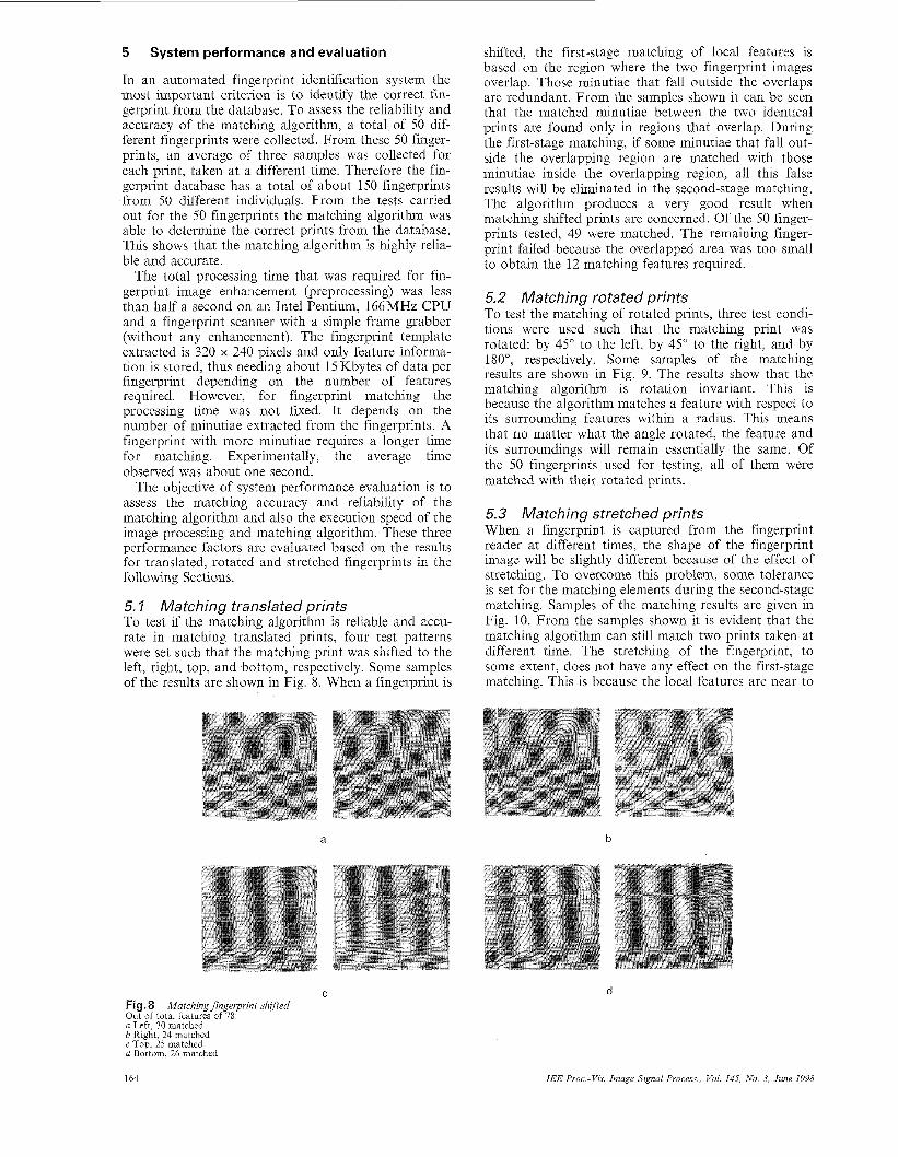
5, I Matching translated prints To test if the matching algorithm is reliable and accu- rate in matching translated prints, four test patterns were set such that the matching print was shifted to the left, right, top, and bottom, respectively. Some samples of the results are shown in Fig. 8. When a fingerprint is
a
shifted, the first-stage matching of local features is based on the region where the two fingerprint images overlap. Those minutiae that fall outside the overlaps are redundant. From the samples shown it can be seen that the matched minutiae between the two identical prints are found only in regions that overlap. During the first-stage matching, if some minutiae that fall out- side the overlapping region are matched with those minutiae inside the overlapping region, all this false results will be eliminated in the second-stage matching. The algorithm produces a very good result when matching shifted prints are concerned. Of the 50 finger- prints tested, 49 were matched. The remaining finger- print failed because the overlapped area was too small to obtain the 12 matching features required.
5.2 Matching rotated prints To test the matching of rotated prints, three test condi- tions were used such that the matching print was rotated: by 45" to the left, by 45" to the right, and by 180", respectively. Some samples of the matching results are shown in Fig. 9. The results show that the matching algorithm is rotation invariant. This is because the algorithm matches a feature with respect to its surrounding features within a radius. This means that no matter what the angle rotated, the feature and its surroundings will remain essentially the same. Of the 50 fingerprints used for testing, all of them were matched with their rotated prints.
5.3 Matching stretched prints When a fingerprint is captured from the fingerprint reader at different times, the shape of the fingerprint image will be slightly different because of the effect of stretching. To overcome this problem, some tolerance is set for the matching elements during the second-stage matching. Samples of the matching results are given in Fig. 10. From the samples shown it is evident that the matching algorithm can still match two prints taken at different time. The stretching of the fingerprint, to some extent, does not have any effect on the first-stage matching. This is because the local features are near to
b
C Fig. 8 Matching fingerprint shijied Out of total features of 78: a Left, 30 matched 6 Right, 24 matched c Top, 25 matched d Bottom, 26 matched
d
164 IEE Proc -Vis. Image Signal Process., Vol. 145, No. 3, June 1998
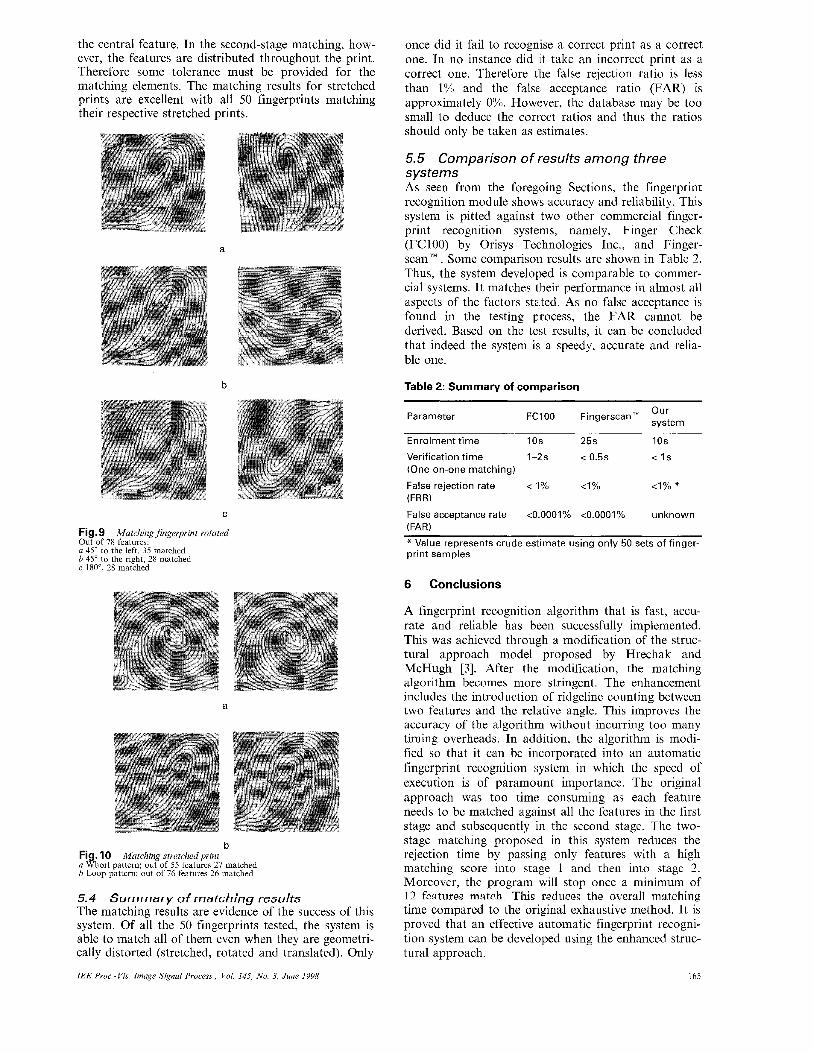
the central feature. In the second-stage matching, how- ever, the features are distributed throughout the print. Therefore some tolerance must be provided for the matching elements. The matching results for stretched prints are excellent with all 50 fingerprints matching their respective stretched prints.
Fig.9 Matching fingerpvint rotated Out of 78 features: a 45" to the left, 35 matched b 45" to the right, 28 matched c 180", 28 matched
a
b Fig. 10 Matching stvetchedprint a Whorl pattern; out of 55 features 27 matched b Loop pattern; out of 76 features 26 matched
5.4 Summary of matching results The matching results are evidence of the success of this system. Of all the 50 fingerprints tested, the system is able to match all of them even when they are geometri- cally distorted (stretched, rotated and translated). Only
IEE Proc.-Vis. Image Signal Process., Vol. 145, No. 3. June 1998
once did it fail to recognise a correct print as a correct one. In no instance did it take an incorrect print as a correct one. Therefore the false rejection ratio is less than 1% and the false: acceptance ratio (FAR) is approximately 0%. However, the database may be too small to deduce the correct ratios and thus the ratios should only be taken as estimates.
5.5 Comparison of results among three systems As seen from the foregoing Sections, the fingerprint recognition module shows accuracy and reliability. This system is pitted against two other commercial finger- print recognition systems, namely, Finger Check (FC100) by Orisys Technologies Inc., and Finger- scan'". Some comparison results are shown in Table 2. Thus, the system developed is comparable to commer- cial systems. It matches their performance in almost all aspects of the factors staked. As no false acceptance is found in the testing process, the FAR cannot be derived. Based on the test results, it can be concluded that indeed the system is a speedy, accurate and relia- ble one.
Table 2: Summary of comparison
Parameter FCIOO Fingerscan'" Our system
Enrolment time 10s 25s 10s
Verification time 1-2s < 0.5s < Is (One-on-one matching)
False rejection rate < 'I% <I% <I% * (FRR)
False acceptance rate <0.0001% <0.0001% unknown (FAR) * Value represents crude estimate using only 50 sets of finger- print samples
6 Conclusions
A fingerprint recognition algorithm that is fast, accu- rate and reliable has been successfully implemented. This was achieved through a modification of the struc- tural approach model proposed by Hrechak and McHugh [3]. After the modification, the matching algorithm becomes morle stringent. The enhancement includes the introduction of ridgeline counting between two features and the relative angle. This improves the accuracy of the algorithm without incurring too many timing overheads. In addition, the algorithm is modi- fied so that it can be incorporated into an automatic fingerprint recognition system in which the speed of execution is of paramount importance. The original approach was too time consuming as each feature needs to be matched against all the features in the first stage and subsequently in the second stage. The two- stage matching proposed in this system reduces the rejection time by passing only features with a high matching score into stage 1 and then into stage 2. Moreover, the program will stop once a minimum of 12 features match This reduces the overall matching time compared to the original exhaustive method. It is proved that an effective automatic fingerprint recogni- tion system can be develloped using the enhanced struc- tural approach.
165
7 References
1 MOAYER, B., and FU, K.S.: ‘A tree system approach for finger- print pattern recognition’, ZEEE Trans., 1986, PAMT-8, (3), pp. 3 76-3 8 7
2 ISENOR, D.K., and ZAKY, S.G.: ‘Fingerprint identification using graph matching’, Pattern Recognit., 1986, 19, (2), pp. 113- 122
3 HRECHAK, A.K., and MCHUGH, J.A.: ‘Automated finger- print recognition using structural matching’, Pattern Recognit., 1990, 23, (8), pp. 893-904 SHERLOCK, B.G., MONRO, D.M., and MILLARD, K.: ‘Fin- gerprint enhancement by directional Fourier filtering’, ZEE Proc., Vision, Image Sigxal Process., 1994, 141, (2), pp. 87-94
5 NALINI, K.R., KARU, K., CHEN, S., and JAIN, A.K.: ‘A real-time matching system for large fingerprint databases’, ZEEE Trans. Pattern Anal. Mach. Zntell., 1996, 18, (8), pp. 799-813
6 PAVLIDIS, T.: ‘Algorithms for graphical and image processing’, Comput. Graph. Image Process., 1982, 20, pp. 133-157
7 SHERLOCK, B.G., MONRO, D.M., and MILLARD, K.: ‘Algorithm for enhancing fingerprint images’, Electron. Lett., 1992, 28, (18), pp. 1720-1721
4
8 XIO, Q., and RAAFAT, H.: ‘A combined statistical and struc- tural approach for fingerprint image postprocessing’. Proceedings of IEEE international conference on Systems, man and cybernet- ics, Los Angeles, CA, USA, Nov. 1990, pp. 331-335
9 TAMURA, H.: ‘A comparison of line thinning algorithms from digital geometry viewpoint’. Proceedings of fourth international joint conference on Pattern recognition, Kyoto, Nov. 1978, pp. 71 5-719
10 HILDITCH, C.J.: ‘Linear skeletons from square cupboards’, Machine Zntell., 1969, 4, pp. 403-420
11 NACCACHE, N.J., and SHJNCHAL, R.: ‘An investigation into the skeletonization approach of Hilditch’, Pattern Recognit., 1984, 17, (3). VI). 279-284 , I , _ _
12 JANG, B.K., and CHIN, R.T.: ‘Analysis of thinning algorithms using mathematical morphology’, IEEE Trans. Pattern Anal. Machine Intell., 1990, 12, (6), pp. 541-551
13 XU, W., and WANG, C.: ‘CGT: a fast thinning algorithm imple- mented on a sequential computer’, ZEEE Trans., 1987, SMC-17,
14 FEIGIN, G., and BEN-YOSEF, N.: ‘Line thinning algorithm’, Proc. SPIE - Znt. Soc. Opt. Eng., 1984, 397, pp. 108-112
15 ZHOU, R.W.,, QUEK, C., and NG, G.S.: ‘Novel single-pass thinning algorithm’, Pattern Recognit. Lett., 1995, 16, (12), pp. 1267-1275
16 GONZALEZ, R.C., and WOODS, R.E.: ‘Digital image process- ing’ (Addison-Wesley, 1992)
(5), pp. 847-851
166 IEE Proc.-Vis. Image Signal Process., Vol. 145, No 3, June 1998