NOTES FOR GUIDANCE ON THE METHOD OF MEASUREMENT FOR ...
190
Volume 4 Section 2 Notes for Guidance on the Method of Measurement for Road Works Contents Amendment – March 2003 1 NOTES FOR GUIDANCE ON THE METHOD OF MEASUREMENT FOR HIGHWAY WORKS Introduction Chapters I, II and III Item Coverage Extra Over Items Remove From Store and Re-erect/Re-install/Relay Hard Material Dayworks Testing Modification and New Materials Telephone Calls Special Preliminary Items Series 100 Preliminaries General Privately and Publicly Owned Services and Supplies Maintenance of Highways Contraflows (Traffic Safety and Management) Temporary Diversion for Traffic Damage to the Highway Information Boards and Driver Information Signs Series 200 Site Clearance Obstructions Above Ground Level General Site Clearance Take Up or Down Damage to Items Series 300 Fencing Temporary Fencing Concrete Foundations or Longer Posts Series 400 Safety Fences, Safety Barriers and Pedestrian Guardrails Safety Fences Pedestrian Guardrails and Handrails Re-tensioning of Existing Safety Fences and Barriers Series 500 Drainage and Service Ducts Tabulated Billing Drainage and Service Ducts in Structures
Transcript of NOTES FOR GUIDANCE ON THE METHOD OF MEASUREMENT FOR ...

Volume 4 Section 2 Notes for Guidance on the Method of Measurement for Road Works Contents
Amendment – March 2003 1
NOTES FOR GUIDANCE ON THE METHOD OF MEASUREMENT FOR HIGHWAY WORKS
Introduction Chapters I, II and III
Item Coverage Extra Over Items Remove From Store and Re-erect/Re-install/Relay Hard Material Dayworks Testing Modification and New Materials Telephone Calls Special Preliminary Items
Series 100 Preliminaries
General Privately and Publicly Owned Services and Supplies Maintenance of Highways Contraflows (Traffic Safety and Management) Temporary Diversion for Traffic Damage to the Highway Information Boards and Driver Information Signs
Series 200 Site Clearance Obstructions Above Ground Level General Site Clearance Take Up or Down Damage to Items
Series 300 Fencing
Temporary Fencing Concrete Foundations or Longer Posts
Series 400 Safety Fences, Safety Barriers and Pedestrian Guardrails Safety Fences Pedestrian Guardrails and Handrails Re-tensioning of Existing Safety Fences and Barriers
Series 500 Drainage and Service Ducts Tabulated Billing Drainage and Service Ducts in Structures

Volume 4 Section 2 Notes for Guidance on the Method of Measurement for Road Works Contents
Amendment – March 2003 2
Alternative Types of Pavement
Series 600 Earthworks General Processing Materials Compaction and Deposition of Fill Geological Terms Alternative Types of Pavement Capping Hard Material Crib Walling, Reinforced Earth Structures and Anchored Earth
Structures Typical Earthworks Schedules Ground Water Lowering Trial Pits Perforation of Redundant Slabs, Basements and the Like Geotextiles Stated Class of Imported Material Ground Improvement - Vibrated Stone Columns Imported Topsoil and Topsoiling Surcharge Material
Series 700 Pavements
Joints Alternative Types of Pavement Tack Coats Repairs to Existing Carriageways Regulating Course Breaking Up or Perforation of Redundant Pavements
Series 1100 Kerbs, Footways and Paved Areas Steps Bituminous and Cement Bound Regulating Course
Series 1200 Traffic Signs and Road Markings
Road Studs Removal of Road Markings Traffic Signal Installations - Network Cabling
Series 1700 Structural Concrete
Curved Formwork Finishes to Concrete Under bridges and Footbridges
Series 2000 Waterproofing for Concrete Structures
Additional Protective Layers
Series 2400 Brickwork, Blockwork and Stonework General
Volume 4 home page

Volume 4 Section 2 Notes for Guidance on the Method of Measurement for Road Works Introduction
Amendment – March 2003 1
Introduction
The Method of Measurement for Road Works (MMRW) has been based upon the Specification for Road Works (SRW) and the Road Construction Details (RCD) published as Volume 1 and Volume 3 of the Manual of Contract Documents for Road Works. They are intended for use with the Conditions of Contract included in the Model Contract Document for Road Works published as Section 1 of Volume 0 of the Manual of Contract Documents for Road Works.

Volume 4 Section 2 Notes for Guidance on the Method of Measurement for Road Works Chapter I, II and III
Amendment – March 2003 1
Chapters I, II and III
1 Item Coverage Item coverages in the MMRW ensure that the Contractor knows the items of work to be covered by the rates and prices he inserts against the appropriate items in the Bill of Quantities. However, coverages relative to the base item description are not normally included, for example cement in concrete, nor are those contingently and indispensably necessary to enable the work item to be completed satisfactorily, for example nuts and bolts in safety fences. Similarly general obligations are not separately covered, for example obligations set out in the Conditions of Contract or covered in the Preambles to Bill of Quantities. The basic item coverages closely match the SRW and RCD. Hence if changes are introduced into the Specification the item coverages have to be reviewed to ensure that they accurately relate to the revised Specification. Changes to the Specification should not be introduced on the Drawings although revised Drawings may reflect revisions to the Specification in which case reference to the Drawings should be incorporated in the Specification. Conversely item coverages should not be extended to include items of work which are not specified or not shown in the RCD. Item coverages often refer to item coverages set out in one or more other Series. The complete item coverage therefore embodies all such references despite those references appearing to be unconnected with the original item in some cases. 2 Extra Over Items Extra Over (EO) items shown in the MMRW are applied to a base item where a significant additional burden is placed upon the Contractor to undertake extra work of much the same nature as the work covered by the base item. The quantities to be billed for the EO items must be in respect of work included with the quantities for the base item. Consequently the item coverage in respect of the quantities for the EO item comprises a summation of that for the base item and the EO item. 3 Remove From Store and Re-erect/Re-install/Relay The items for remove from store and re-erect, re-install, relay include items which have been removed to store off Site designated by the Overseeing Organisation and items which have been set aside by the Contractor as required by the Contract.e 4 home page 4 Hard Material Excavation in Hard Material occurs in the item coverage for several items of work, for example, fencing, safety fencing, traffic signs and road markings, road lighting and electrical work. The Contract should contain information

Volume 4 Section 2 Notes for Guidance on the Method of Measurement for Road Works Chapter I, II and III
Amendment – March 2003 2
known to the compiler about the existence and extent of Hard Material and this should include existing buried roads and the like. This would not relieve the Contractor of his obligations under the Conditions of Contract. Hard Material is measured extra over normal excavation for earthworks, fencing and drainage and guidance is given under Series 600. 5 Dayworks Where it is anticipated work will be required to be executed on a daywork basis, attention is drawn to the Model Contract Document for Road Works, which sets out the means of providing for Dayworks in the Contract. The Compiler when considering the particular form of contract to be utilised shall decide whether it is appropriate to include Daywork items. The Compiler shall decide whether the deletion of references from within documentation to Dayworks is appropriate. 6 Testing The compiler’s attention is drawn to paragraph 17 of the Preamble to Bill of Quantities which sets out the manner in which testing is either to be allowed for in the rates and prices or measured in the Bill of Quantities. Compliance testing of the permanent works to be carried out by the Contractor at specified frequencies is scheduled by the compiler in Appendix 1/5 to the Specification. Paragraph 2(x) of the Preambles to the Bill of Quantities covers testing listed in Appendix 1/5 and no items should be included in the Bill of Quantities in respect of these tests. Appendix 1/5 may also include tests to be carried out on the permanent works to prove the Overseeing Organisation’s design, or validate design assumptions, and these tests are also covered by paragraph 2(x). Other compliance testing, checking, inspecting, measuring and verifying of workmanship, goods and materials incorporated into the permanent works required to be carried out by the Contractor but not listed in Appendix 1/5 is covered by paragraph 2 (xii) of the Preamble to the Bill of Quantities and no items should be included in the Bill of Quantities in respect of these tests. Tests to be carried out on the permanent works to prove the Overseeing Organisation’s design, or validate design assumptions, but which are not separately listed in Appendix 1/5 are also covered by paragraph 2(xii). Trial construction and associated testing to be carried out by the Contractor for the purpose of proving the Overseeing Organisation’s design or validating design assumptions, e.g. installation and test loading of trial piles in advance of the main piling or loading tests for safety fence posts, shall be measured separately in the relevant Series. The compiler should ensure that appropriate items are included in the Bill of Quantities for these and any similar tests and, where necessary, make appropriate amendments to the Method of Measurement. There are in principle four types of compliance testing as explained in Series 900, Sub-Clause 2 to 5 :
- Production control – costs are covered by the Contractor;

Volume 4 Section 2 Notes for Guidance on the Method of Measurement for Road Works Chapter I, II and III
Amendment – March 2003 3
- Control testing – results are the base for the acceptance of the works and costs are covered by the Overseeing Organisation;
- Additional control testing; - Arbitrary testing.
Type and frequency of testing is also to be found in the relevant Series. Volume 4 home page 7 Modification and New Materials The item coverage applicable to removing from store and re-erecting/reinstalling/relaying various materials includes for modification and new materials to the extent that the requirements are detailed in the Contract. Modification and new materials of which the Contractor was not informed at the time of tender are not covered by this item coverage. 8 Telephone Calls Where provision is made in the Contract telephone calls made by the Overseeing Organisation are reimbursable in the case of the certified actual price but the cost of telephone rental and installation is not reimbursable, as it is included in item coverage for temporary accommodation. 9 Special Preliminary Items The use of Special Preliminary Items is identified in Chapter III Preparation of Bill of Quantities paragraph 4 and the intention is that they are only included in exceptional circumstances as described in sub-paragraphs (a) and (b). The Compiler shall ensure that if items are included that they are adequately covered within the documentation including any required item coverage.
Volume 4 home page

Volume 4 Section 2 Chapter IV Series 100 Notes for Guidance on the Method of Measurement for Road Works Preliminaries
Amendment – March 2003 1
Series 100: Preliminaries
Volume 4 home page
1 General These Notes for Guidance use generic terms and compilers should refer to the proposed particular Form of Contract being used for derivation of contract specific terminology. 2 Privately and Publicly Owned Services and Supplies Particulars of the services and supplies affected by the Permanent Works and any preliminary arrangements for alterations by the owner or authority responsible should be detailed in Appendix 1/16 of the Specification but not included in Items or Sums in the Bill of Quantities, apart from any permanent works for the alterations which are to be provided by the Contractor, for example ducts. Charges by the owner or authority responsible for these alterations will be paid by the Overseeing Organisation after scrutiny. Any alterations to services and supplies required for the Contractor’s temporary works, diversions and the like are the responsibility of the Contractor and are deemed to be covered by the rates and prices in the Bill of Quantities. 3 Maintenance of Highways Appendix 1/17 of the Specification specifies those maintenance functions which will be the responsibility of the Contractor within defined physical limits and time periods. The work scheduled in this Appendix is covered by the rates and prices inserted by the Contractor in the Bill of Quantities. 4 Contraflows (Traffic Safety and Management) There are three possible methods by which contraflows can be planned and designed:
(a) full proposals drawn up by the Overseeing Organisation; (b) outline proposals drawn up by the Overseeing Organisation and
completed by the Contractor; (c) full proposals drawn up by the Contractor.
Requirements under methods (a) or (b) should be scheduled in Appendix 1/17. Method (c) will be deemed as Contractor’s temporary works to be included in the contraflow item.

Volume 4 Section 2 Chapter IV Series 100 Notes for Guidance on the Method of Measurement for Road Works Preliminaries
Amendment – March 2003 2
It is recommended that the contraflow item is always included when traffic management is required thus allowing for Contractor’s proposals as described in method (c) above. Volume 4 home page 5 Temporary Diversion for Traffic The MMRW allows for temporary diversions for traffic to be measured as follows:
(a) Specific Locations - These may include those where, in the opinion of the compiler, the diversionary work is likely to be complicated, expensive, or its impact on or disruption of the Works is likely to be substantial. The description should include the appropriate reference from Appendix 1/18 of the Specification.
(b) Omnibus Item - This should include all diversions of a minor nature scheduled in Appendix 1/18 of the Specification. The omnibus item should not include in its description the references from Appendix 1/18 of the Specification.
(c) A separate omnibus item should always be provided for all diversions at locations proposed by the Contractor.
6 Damage to the Roadway The responsibility for repairing damage to roadways rests with the Contractor unless stated otherwise in Appendix 1/17 or 1/18. The compiler should check whether or not the Conditions of Contract requires the Contractor to insure and indemnify the Overseeing Organisation against loss, damage and claims. If so, this is covered by Preamble 2 (vii) to the Bill of Quantities. 7 Information Boards and Driver Information Signs The items in the Bills of Quantities for Information Boards shall only be in respect of those Information Boards detailed in Appendix 1/21 to the Specification. The Information Boards should not be confused with Driver Information Signs which, when required, will be detailed in Appendix 1/17 to the Specification and are included in the Item Coverage for Traffic Safety and Management.

Volume 4 Section 2 Chapter IV Series 200 Notes for Guidance on the Method of Measurement for Road Works Site Clearance
March 2003 1
Series 200: Site Clearance
Volume 4 home page
1 Obstructions Above Ground Level The various Group I, Feature 3 items of site clearance measured separately are to be referenced on the site clearance drawings and listed in Appendix 2/1. The referencing of items for site clearance can include consolidated references such as - “a house with adjoining garage and outbuildings” provided that full identification is given in, or cross referenced in, Appendix 2/1. 2 General Site Clearance The stated unit of measurement for General Site Clearance is hectare as paragraph 2(i). However there may be circumstance in which this unit of measurement is not appropriate for certain schemes such as those involving a high degree of maintenance work. In these circumstances the compiler may wish to amend the unit of measurement to “item” by the insertion of a Preamble to the Bill of Quantities. In any event the limits of General Site Clearance should be clearly indicated on the drawings. The compiler’s attention is drawn to Specification paragraph 202.3 which refers to cutting back existing trees, bushes and hedges. Item coverage paragraph 5(h) allows the tenderer to price this requirement. However it is recommended that the extent of the cutting back to existing trees be taken into consideration since this aspect may be more appropriately measured in accordance with Series 3000, particularly if specialist activities such as tree surgery are required. 3 Take Up or Down Take up or down and set aside for re-use should only be used for those materials or items that are required to be stored on Site by the Contractor prior to re-use. Take up or down and remove to store off Site is appropriate to those materials or items which are required to be taken off Site to a store designated and described in the Contract. These requirements should be detailed in Appendix 2/3 of the Specification including the distance to the store. The item(s) for take up or down and remove to tip off Site shall be used only when no item for General Site Clearance has been included in the Bill of Quantities for that particular area. In this case it is essential that all items to be removed to tip off Site are measured separately in accordance with paragraphs 8 to 11. 4 Damage to Items

Volume 4 Section 2 Chapter IV Series 200 Notes for Guidance on the Method of Measurement for Road Works Site Clearance
March 2003 2
Item coverage includes for replacing items damaged in the process of taking up or down and setting aside or storing. It is the Contractor’s responsibility to ascertain at the time of tender the extent of any damage which may occur and to make the appropriate allowance in his rates and prices. Volume 4 home page

Volume 4 Section 2 Chapter IV Series 300 Notes for Guidance on the Method of Measurement for Road Works Fencing
March 2003 1
Series 300: Fencing
Volume 4 home page
1 Temporary Fencing The Specification requires the Contractor to erect temporary fencing in all situations where he does not provide permanent fencing immediately. To comply with the Specification, Health and Safety Regulations and the Conditions of Contract the Contractor has the choice of a range of four specified types of temporary fencing. This temporary fencing is not shown on the Drawings nor is it included in the Bill of Quantities. However, should some specific temporary fencing be required by the Overseeing Organisation then this should be shown on the Drawings and included within Appendix 3/1 and the Bill of Quantities. The Compiler should ensure that the obligations under the Form of Contract being utilised are sufficient and adequately cover the particular requirements of an individual scheme. 2 Concrete Foundations or Longer Posts Items are provided in the MMRW for concrete foundations to timber posts. These are only to be measured where such a requirement is identified in Appendices 1/15 or 3/1 of the Specification. Foundations in all other circumstances, including those for all posts other than timber, shall be deemed to be included within the fencing item to which they relate. Locations where longer posts are required should also be identified in Appendices 1/15 or 3/1, a specific Type reference should be given, and reference made in item descriptions.
Volume 4 home page

Volume 4 Section 2 Chapter IV Series 400 Notes for Guidance on the Method of Measurement for Road Works Safety Barriers and Pedestrian Guardrails
March 2003 1
Series 400: Safety Barriers and Pedestrian Guardrails
Volume 4 home page
1 Safety Barriers The MMRW provides for three categories of curvature for payment purposes. Curves which are made up from individual straight lengths of beams should not be considered to be small lengths of straight fence. They should be measured as curved fences within the Group II features in MMRW. The radius is to be considered to be the radius equal to that of the arc which passes through the posts. 2 Pedestrian Guardrails and Handrails Curves which are made up from individual straight lengths should not be considered as curved elements but as straight guardrails or handrails. Where the rails are actually curved they should be measured as curved guardrails or handrails as described by the specific radius. 3 Re-tensioning of Existing Safety Fences and Barriers Where re-tensioning of existing safety fences and safety barriers when connected to new is required the Drawings and/or Specification should clearly identify the work.
Volume 4 home page

Volume 4 Section 2 Chapter IV Series 500 Notes for Guidance on the Method of Measurement for Road Works Drainage and Service Ducts
March 2003 1
Series 500: Drainage and Service Ducts
Volume 4 home page
1 Tabulated Billing The billing of pipe runs of varying diameter and specification with their attendant adjustment items produces a lengthy Series 500 bill. It is suggested that a tabulated method is used as shown in the example overleaf. This method will reduce the repetition of item descriptions. This method can also be extended to manholes and chambers. Where non-standard or small quantities exist they would be best billed in the traditional manner. 2 Drainage and Service Ducts in Structures The extent of the quantities included in the item for drainage and service ducts to a structure and their interface with non-structural drainage should be clearly shown on the Drawings. The quantities making up this item should either be scheduled in an appendix or on a drawing of the structure. 3 Alternative Types of Pavement There is no requirement to provide separate drainage Bills of Quantities corresponding with each alternative Type of Pavement. Measurement of drainage must be based upon the thinnest construction permitted for any of the alternative Types of Pavement irrespective of the Type of Pavement chosen by the Contractor.
Volume 4 home page

Volume 4 Section 2 Chapter IV Series 500 Notes for Guidance on the Method of Measurement for Road Works Drainage and Service Ducts
March 2003 2
Tabulated Drainage Example 1 Drains Item Description Unit Quantity Rate Lm c
‘A’ mm internal diameter drain or sewer specified trench and bedding type or design group ‘B’ in trench depth to invert exceeding 2 metres, but not exceeding 4 metres, average depth to invert ‘C’ metres. Adjustment on this item for variation greater than 150mm above or below the average depth of ‘C’ metres per 25mm of variation in excess of 150mm. Rate per metre ‘D’ (not to be extended).
‘A’ dia
‘B’ Trench and bedding type or
design group
‘C’ ave. depth
‘D’ adjust. rate
21 150 6 2.625 m 54 22 225 7 2.950 m 18 23 300 7 2.875 m 78 24 450 8 3.275 m 157
NOTE: Adjustment rate ‘D’ shall apply to both increases and decreases of average depth in excess of 150mm, and will result in either a positive or negative adjustment of the rate. 2 Chambers Item Description Unit Quantity Rate Lm c
Chamber specified design group ‘A’ sub-type ‘B’ with ‘C’ ‘D’ and frame depth to invert exceeding ‘E’ metres but not exceeding ‘F’ metres.
‘A’ design group
‘B’ sub-type
‘C’ cover grade
‘D’ type
‘E’ depth min.
‘F’ range max.

Volume 4 Section 2 Chapter IV Series 500 Notes for Guidance on the Method of Measurement for Road Works Drainage and Service Ducts
March 2003 3
76 2 - grade A cover 1 2 no 10 77 3 a grade A cover 1 2 no 60
78 3 b grade A cover 1 2 no 70 79 3 c grade A cover 2 3 no 55

Volume 4 Section 2 Chapter IV Series 600 Notes for Guidance on the Method of Measurement for Road Works Earthworks
March 2003 1
Series 600: Earthworks
Volume 4 home page
1 General Where the Contractor has obligations in respect of classification of earthworks materials then these obligations include sampling and testing in accordance with the directions given in the Contract. The Contractor retains overall responsibility to provide acceptable earthworks materials as defined in the Contract both when classification and determination of acceptability is done by the Contractor and when it is done by the Overseeing Organisation. The attention of compilers is drawn to the criteria for classification of earthworks materials which are set down in Clause 601.1 and Table 6/1 of the Specification as modified and extended to suit the requirements of any particular Contract by Appendix 6/1. Classification is based on the simple principle that all materials which meet the requirements for acceptability for use as fill forming any part of the Permanent Works, whatever their usage, are termed acceptable materials. Materials which fail to meet the criteria for acceptability for any of the classes of fill required for the Permanent Works are termed unacceptable materials. Separation between acceptable and unacceptable material in the measurement of excavation, disposal of material, deposition of fill and compaction of fill must conform strictly with the acceptability parameters established in the Specification. In particular, all materials excavated from within the Site, which at the point of excavation, comply with the acceptability requirements for any of the various classes of fill permitted by the Contract, notwithstanding that materials in any particular class may be surplus to the requirements of the Contract for that class, or outside the limits for other classes, shall be classified and measured as excavation of acceptable material. For the avoidance of doubt the Specification and the Method of Measurement provide for the inclusion amongst excavated acceptable materials of the lower categories of material not suitable for use in structural embankments but acceptable for use as fills in landscaping areas (Class 4 fills) and environmental earthwork bunds. These lower categories of material must therefore be included in the measurement of excavation, disposal of material, deposition of fill and compaction of fill as acceptable material. Those materials which, on excavation, fall outside the specified limits for acceptability or require further processing to render them acceptable for use in the Works, shall be classified and measured as excavation of unacceptable materials.

Volume 4 Section 2 Chapter IV Series 600 Notes for Guidance on the Method of Measurement for Road Works Earthworks
March 2003 2
It is emphasised that the Specification and the Method of Measurement only provide for a change in classification and measurement from excavation in unacceptable material to deposition of acceptable material where the Overseeing Organisation specifies that materials classified and measured as unacceptable on excavation shall be processed to render them acceptable for use as fill in the Permanent Works. Furthermore, compilers are advised that neither the Specification nor the Method of Measurement provide for, nor in any circumstances should they be amended to provide for, the deposition, importation or compaction of unacceptable materials. If the Contractor opts to render unacceptable material acceptable for use in the Works (as opposed to when the Overseeing Organisation has specified that this should take place) then measurement shall be as though the unacceptable material had been disposed of and acceptable material of the class rendered acceptable, imported. If the Contract requires that unacceptable material is rendered acceptable then that material is measured as treatment of unacceptable material Class U1 and then considered to be acceptable material arising from the Site.
2 Processing Materials When the Overseeing Organisation decides to assess and designate material within the excavation which can be processed into acceptable material for general fill or selected fill, he should state the Class or Classes of acceptable material with which the processed material must comply. The class of the processed material should be specified and the location of its excavation should be shown on the Drawings and referenced. The sequence of measurement items is as follows:
(i) Excavation of unacceptable material Class U1 (in cutting etc). (ii) Extra over excavation for excavation in Hard Material in cutting and
other excavations. (iii) Processing of unacceptable material Class U1 to acceptable material
stated class or classes. (iv) Deposition of acceptable material (in embankments etc). (v) Compaction of acceptable material (in embankments etc).
The earthworks schedules may require additional items under the fill sections depending on Specification and deposition requirements.
3 Compaction and Deposition of Fill

Volume 4 Section 2 Chapter IV Series 600 Notes for Guidance on the Method of Measurement for Road Works Earthworks
March 2003 3
The volume of material measured in Compaction of Fill should include the quantities measured in Imported Fill and Deposition of Fill. The quantity of material measured in Deposition of Fill should relate only to the acceptable material arising from the Site including material so arising as unacceptable but required to be processed to become acceptable and not that measured in Imported Fill. 4 Geological Terms Excavated material which comes within the definition of acceptable material should be billed as stated in the MMRW/LSID and not described by a geological term or common name e.g. chalk. 5 Alternative Types of Pavement Where the Contract provides for the Contractor to select the Type of Pavement a separate Earthworks Bill of Quantities is required to correspond with each alternative Type of Pavement. The measurement for each of the individual Bills of Quantities is to be based on the thinnest construction permitted for each Type of Pavement. The tenderer is required to price and extend only the Earthworks Bill which applies to his selected Type of Pavement.
6 Capping The material required and detailed in the Contract for use as capping may be obtained from various specified classes of material. This material should not be billed as “capping” material but should be as described in the MMRW and LSID under the appropriate feature classification for acceptable material. 7 Hard Material This note gives general guidance on the way Hard Material should be dealt with when included in contract documentation. The definition of Hard Material in the MMRW has evolved over a period of time and it should not be changed. The inclusion of the definition in contract documentation effectively excludes all other forms of definition. The aim is to achieve consistency of approach throughout the country giving benefit to the Overseeing Organisation and Contractors. There are two parts to the definition and in general they should be compatible.
The excavation of Hard Material has been recognised in the MMRW as warranting measurement as extra over normal excavation because of the relative cost of the removal of such material. Hard Material is defined for measurement purposes only, in Chapter I Definitions, paragraph 1(h) as the following:
(i) material so designated in the Preambles to Bill of Quantities;

Volume 4 Section 2 Chapter IV Series 600 Notes for Guidance on the Method of Measurement for Road Works Earthworks
March 2003 4
and/or
(ii) material which requires the use of blasting, breakers or splitters for its removal but excluding individual masses less than 0.20 cubic metres.
Sub-paragraph (ii) of the definition outlines the means of determining the volume of Hard Material when circumstances preclude the use of sub-paragraph (i). These circumstances should be rare. At the time of tender the Contractor should generally be made aware of what material is to be expected and he is deemed to have supplemented this by inspection where the Conditions of Contract so require. At the time of tender the Overseeing Organisation should designate which strata or deposits are to be measured as being Hard Material; bound materials in existing pavements and the like will always be Hard Material. In bulk earthworks, materials which in the Overseeing Organisation’s judgement may reasonably be removed by using conventional rippers, taking into account factors such as the location and extent of the excavation, the size of the project and other limitations, should not be designated as Hard Material. If the material found during the course of construction is that which was shown at the time of tender, or could be ascertained by the Contractor’s pre-tender inspection, then admeasurement should follow the same designations irrespective of the actual hardness of the material. If the material found in the course of construction is not as described in the tender documents or apparent by inspection, the Contractor may raise a claim if permitted under the Conditions of Contract. It will then be for the Contractor to demonstrate that the material could not reasonably have been foreseen and that extra costs had arisen, according to the terms of the Contract.
Difficulties can arise when the extent of designated strata is not clear. Soils are widely variable and the interface between strata can be indistinct: fragmented Hard Materials might gradually merge with other soils for example. The points to which the measurements of Hard Material strata are taken may then be ascertained by the application of sub-paragraph (ii) above. At the time of tender the Overseeing Organisation has to make a judgement regarding the extent of designated strata. In the course of construction a similar judgement will be required based upon observations in the field. Hard Material is only measured separately in Series 300: Fencing, Series 500: Drainage and Series 600: Earthworks. It is not likely that the application of sub-paragraph (ii) above will cause problems of measurement under Series 500. Drainage excavation usually will be done with backhoes appropriate to the size of the trench and it is unlikely that the Contractor would use other plant unless it was essential. The extent of the designated strata therefore should be apparent from performance and only a limited amount of judgement would be required. In bulk earthworks the position might not be so clear. For example, the Contractor might be excavating by means of scrapers and in areas where designated Hard Material strata are shown the scrapers might be augmented by other plant; the extent to which such plant is actually used would not show the limit of the Hard Material

Volume 4 Section 2 Chapter IV Series 600 Notes for Guidance on the Method of Measurement for Road Works Earthworks
March 2003 5
strata and the Overseeing Organisation would have to give a decision on the extent of the designated strata. Paragraph 13(c) of the Preambles to the Bill of Quantities sets out three methods of designating Hard Material for measurement purposes:
(a) designated strata (b) designated deposits with limits shown on the Drawings
(c) existing pavements, footways, paved areas and foundations.
The selection of (a) or (b) above is achieved by applying professional judgement to borehole data and other sources of information to determine those identifiable strata and deposits which are likely to create significant costs relative to the excavation of other materials in the Works. It is intended that the results of this judgement should be included in the Contract. The compiler should ensure that only one method of designation is used for any particular material. Once a strata or deposit has been designated as Hard Material it is not subject to reclassification. Conversely, the fact that a material similar to that designated as Hard Material in a deposit within defined limits shown on the Drawings, may be found elsewhere does not indicate that it will be measured as Hard Material in the other location. Designation of material as Hard Material is for measurement purposes and is not intended to indicate that the material has any particular level of strength, bearing capacity or other characteristic. Where Hard Material is designated by reference to named strata alone the total quantity excavated from within those strata is subject to admeasurement. Where deposits are designated by limits shown on the Drawings that volume is measured and paid for as Hard Material. For both methods of designation the material actually excavated may not fall within the definition of Hard Material as set out in sub-paragraph 1(h)(ii) of Chapter I. Hard Material designated under Preamble 13(c) i.e. existing pavements, footways, paved areas and foundations is subject to admeasurement but excluding any unbound materials within the pavement, footway, paved area, or foundation.
Volume 4 home page Notwithstanding the means of designating Hard Material, care must be taken to ensure that the quantity inserted in the Bill of Quantities is consistent with the information made available to the Contractor.
8 Crib Walling, Reinforced Earth Structures and Anchored Earth Structures When designed by the Contractor, these structures are to be measured under Series 2500. The references throughout Series 600 to these structures are included only to allow the Contractor to produce his priced schedules of quantities required by Preamble 16 to the Bill of Quantities.

Volume 4 Section 2 Chapter IV Series 600 Notes for Guidance on the Method of Measurement for Road Works Earthworks
March 2003 6
9 Typical Earthworks Schedules The schedules shown overleaf illustrate information to be provided by the Overseeing Organisation and incorporated in the Contract. The sub-division of the schedules should be based on substantial changes in the type of construction or at major physical obstructions. For example a sub-division may be appropriate in the roadworks schedule where a cut/fill interface is reached or where an area of embankment is to be surcharged. 10 Ground Water Lowering This item is for use when the Overseeing Organisation has either designed the method of de-watering or specified the reduced water level. It is not intended for the normal Site drainage as specified under General Requirements (Clause 602 of SRW). 11 Trial Pits The item for excavation of trial pits should be used for specific trial pits specified in the Contract or ordered by the Overseeing Organisation during the currency of the Works. It is not intended for the various testing and sampling required by the Contract and scheduled in Appendix 1/5 or 1/6. Trial pits excavated for the sole purpose of classification of earthworks materials are not to be measured as these are covered by Preamble 2(vii) to the Bill of Quantities; however, the extent of sampling should be clearly defined in the tender documents.
12 Perforation of Redundant Slabs, Basements and the Like The location and extent of perforation required should be detailed in Appendix 2/1. 13 Geotextiles Laps which are described in the Specification are included in item coverage for geotextiles and not measured separately. The measurement of geotextile shall be the developed area of the geotextile and this will include turn ups at edges, returns for anchorages and laps shown on the drawings. Volume 4 home page 14 Stated Class of Imported Material Bill compilers should not utilise Group 1 Feature 2, stated class of imported material, when excavated acceptable materials Classes 1 to 4 arising from site are inadequate or not present to satisfy the specific requirements of placement of acceptable material in particular locations. Any shortfall of acceptable materials Class 1 to 4 should be measured within Group 1 Feature 1.

Volume 4 Section 2 Chapter IV Series 600 Notes for Guidance on the Method of Measurement for Road Works Earthworks
March 2003 7
It is the responsibility of the compiler to make the appropriate engineering judgement in balancing those classes or sub-classes of acceptable materials that are available to the Contractor from excavations measured in Series 600 to the quantity of acceptable materials required for placement in the Works. 15 Ground Improvement - Vibrated Stone Columns Vibrated stone columns require separate itemisation for different diameters. Due to the nature of the process the final diameter of the stone column will differ from the diameter of the original hole formed. Classification should relate to the minimum diameter required, as specified in the Contract. Should the final diameter be larger than the minimum specified this is the responsibility of the Contractor and he should make allowance to his rates and prices in accordance with item coverage paragraph 113 of Series 600. 16 Imported Topsoil and Topsoiling When there is a shortfall of site won topsoil and the need to measure items for imported topsoil is identified then corresponding items for topsoiling should be measured in accordance with paragraphs 77 to 81. This measurement should include for the placing of topsoil Class 5A excavated from within the site and the placing of imported topsoil Class 5B. 17 Surcharge Material Excavation of Acceptable Material which is to be used as Surcharge, should be (a) included in the Earthworks Schedule and (b) identified separately. Note 9 above (on page 5) and page 9 of this Series provide a proforma folded A3-size sheet with a “Typical Roadworks Earthworks Schedule”. Below the heading of that schedule in the third row, is a sample entry “(Surcharge Ch 910-1155)”. The earthworks schedules should include the volumes of surcharge material placed and removed. Sufficient information should be given by the Overseeing Organisation in the tender documents (whether specified, drawn or quantified) to enable the surcharge requirement and the likely loss of surcharge material to be established both for inclusion in the earthworks balance and to enable the tenderer to separately identify these volumes. The inclusion at paragraph 18 of
“(p) disposal of surcharge material (as this Series paragraph 39);”
as item coverage is not intended to specifically cover the disposal of the measured volume of residual surcharge material as calculated in accordance with paragraph 15 (c). The measurement and earthworks balance is based on the re-use of residual surcharge material. Specification sub-Clauses 608.6 and 608.7 and Appendix 6/3 are particularly relevant. The Contractor may, however, wish for his own operational reasons to import material for the finished embankment and dispose of the residual surcharge, e.g. subject to (a) Appendix 6/3, and/or (b) Appendix 1/13. The replacement by the Contractor of acceptable material arising on site is an obligation imposed on the Contractor

Volume 4 Section 2 Chapter IV Series 600 Notes for Guidance on the Method of Measurement for Road Works Earthworks
March 2003 8
under sub-Clause 602.3 of the Specification. Item coverage for excavation has therefore been extended to include the cost of the Contractor’s optional disposal of surcharge. This principle would apply also to any constraints imposed by the Employer under the Contract which, in all practicality, prevented the re-use of surcharge material. MMRW measurement paragraphs have been drawn up to apply universally and in order to provide for use of all available acceptable arisings irrespective of optional or imposed constraints which obviate such use. Due allowance should be made by tenderers in their rates against the measured quantities to reflect their actual disposal/import requirements. Item coverage paragraph 18(p) provides for disposal of surcharge only where the Contractor opts for disposal to suit his method of working or where constraints in the contract inhibit re-use of surcharge material. Concerning Disposal of Material, MCRW 4.1 (MMRW) Series 600, paragraph 35(a) states that
“The measurement of disposal of acceptable material shall be, for acceptable material excluding Class 5A – the volume excavated from within the Site measured in this Series ……”
It is intended that this measurement should include the volume of Surcharge for removal measured under paragraph 15(c) and itemised under paragraph 16(Group III, Feature 8). The earthworks balance and the measurement paragraphs are based on the re-use of the residual material within the completed embankments (ie the final compacted volume after removal of surcharge). It is not uncommon for tenderers to have to include in their rates for essential items of work which are not actually measured. For example, excavation and backfilling of working space, over-filling an embankment for protection then trimming back to formation. To summarise, the measurement paragraphs include:
(a) the temporary surcharge volume in the total measured deposition and compaction volumes.
By later deducting
(b) the re-excavated surcharge volume at the end of the specified consolidation period,
these paragraphs operate to calculate
(c) the final disposal or import requirement based on the material required for the finished embankment (ie after removal of surcharge)
and to cover only

Volume 4 Section 2 Chapter IV Series 600 Notes for Guidance on the Method of Measurement for Road Works Earthworks
March 2003 9
(d) the loss of surcharge material due to consolidation of the embankment and its foundation.
Volume 4 home page To illustrate the above, three worked examples using a theoretical Bill of Quantities are included below: Example No 1 Shortfall of Excavated Material. Compaction of Fill = 1,000,000m3. Includes surcharge of 250,000m3. Excavation from cuttings etc = 600,000m3 Excavation in removal of surcharge - Paragraph 15 ( c) = 220,000m3* 820,000m3 Imported Fill = 1,000,000m3 – 820,000m3 = 180,000m3 Deposition of Fill 1,000,000m3 – 180,000m3 = 820,000m3 Disposal of Material 820,000m3 – (1,000,000m3 – 180,000m3) = 0m3 * Reflects settlement in embankment of 30,000m3. Example No 2 Surplus of Excavated Material. Compaction of Fill = 1,000,000m³. Includes surcharge of 250,000m³. Excavation from cuttings etc. = 800,000m³ Excavation in removal of surcharge - Paragraph 15 (c) = 220,000m³ * 1,020,000m³ Imported Fill = 1,000,000m³ - 1,020,000m³ = -20,000m³
Therefore Import Required = 0m³ Deposition of Fill = 1,000,000m³ - 0m³ = 1,000,000m³ Disposal of Material = 1,020,000m³ - (1,000,000m³ - 0m³) = 20,000m³ *Reflects settlement in embankment of 30,000m³ Example No 3 No site won material. Embankments constructed using Imported Fill. Compaction of Fill = 1,000,000m³ Includes surcharge of 250,000m³ Excavation from cuttings etc. = 0m³ Excavation in removal of surcharge - Paragraph 15(c) = 220,000 m³* 220,000m³ Imported Fill = 1,000,000m³ - 220,000m³ = 780,000m³

Volume 4 Section 2 Chapter IV Series 600 Notes for Guidance on the Method of Measurement for Road Works Earthworks
March 2003 10
Deposition of Fill** = 1,000,000m³ - 780,000m³ = 220,000m³ Disposal of Material = 220,000m³ - (1,000,000m³ - 780,000m³) = 0m³ *Reflects settlement in embankment of 30,000m³. ** Reflects temporary deposition of imported material used in surcharge.
Volume 4 home page

Volume 4 Section 2 Chapter IV Series 600 Notes for Guidance on the Method of Measurement for Road Works Earthworks
March 2003 11
TYPICAL ROADWORKS EARTHWORKS SCHEDULE EXCAVATION FILL
ACCEPTABLE UNACCEPTABLE
LAND-SCAPING
SELECTED GRANULAR SELECTED COHESIVE
3 U1 U2
GENERAL
4 6A 6B 6C 6D 6E 6F 6G 6R 7E 7F 7G 7I
Other than
Class 3 and C
lass 5A
5A
Above Earthw
orks Outline
Below
Earthworks O
utline
Above Earthw
orks Outline
Below
Earthworks O
utline
Total Acceptable other than C
lass 5A
(to include processed U1 m
aterial)
Above Earthw
orks Outline
Below
Earthworks O
utline
Above Earthw
orks Outline
Below
Earthworks O
utline
Total Excavation other than Class 5A
EO H
ard Material
Processing of Class U
1 LOCATION
Embankm
ents, etc
Strengthened Embankm
ents
On Sub-base, C
apping, etc
Environmental B
unds
Fill to Landscape Areas
Starter Layer (Below
Water)
Starter Layer (Coarse)
Starter Layer
Starter Layer under PFA
Capping for C
ement Stabilisation
Capping
Fill to Gabions
Capping for Lim
e and Cem
ent Stabilisation
Capping for Lim
e Stabilisation
Capping for C
ement Stabilisation
PFA C
apping for Cem
ent Stabilsation
Capping for Lim
e and Cem
ent Stabilisation
Total Fill Material
1 2 3 4 5 6 7 8 9 10 11 12 13 14 15 16 17 18 19 20 21 22 23 24 25 26 27 28 29 30 31 ROADWORKS
Main Carriageway Ch 0-700
Main Carriageway Ch 700-1600
(Surcharge) Ch 910-1155 Interchanges Reference 1 Side Roads Reference 4 WATERCOURSES
New: Reference X
Enlarged: Reference Y Intercepting Ditches:
Ch 250-500
Clearing: Reference Z To include other such as:
Motorway Compounds, Accommodation Works, Service Areas, Farm access roads.
Sub-totals
ROADWORKS TOTAL
Notes: (i) Columns 7 and 8 should include the volumes of materials which are to be processed into acceptable material (ii) Column 11 should include the volume of material which will be processed from U1 material

Volume 4 Section 2 Chapter IV Series 600 Notes for Guidance on the Method of Measurement for Road Works Earthworks
March 2003 12
TYPICAL STRUCTURES EARTHWORKS SCHEDULE EXCAVATION FILL
ACCEPTABLE UNACCEPTABLE GENERAL SELECTED GRANULAR SELECTED COHESIVE Other than 1C
or 6B Specified
1C Specified
6B 6H 6I 6J 6N/P 7A 7B 7C 7D 3
Other than C
lass 3 and Class 5A
Total other than Class 5A
U1 U2 Total
Total other than Class 5A
(to include processed U
1 material)
EO H
ard Material
Processing of Class U
1
STRUCTURE
Above Structural Foundations
Fill to Structures
On B
ridges
Starter Layer (Below
Water)
Starter Layer (Coarse)
Above Structural Foundations
Fill to Structures
Drainage Layer to R
einforced Earth*
Drainage Layer to A
nchored Earth*
Reinforced Earth*
Anchored Earth*
Reinforced Earth*
Anchored Earth*
Above Structural Foundations
Fill to Structures
Above Structural Foundations
Fill to Structures
Above Structural Foundations
Fill to Structures
Reinforced Earth*
Reinforced Earth*
Reinforced Earth*
Total Fill Material
1 2 3 4 5 6 7 8 9 10 11 12 13 14 15 16 17 18 19 20 21 22 23 24 25 26 27 28 29 30 31 32 High Lane Bridge Low Road Underpass Stated Structure To include others such as:
Service Area Bridges, Maintenance Compound Bridges, Accommodation Works Bridges, Culverts, Retaining structures.
Sub-totals
STRUCTURES TOTALS
* Only to be used when the structure is not within Designated Outlines

Volume 4 Section 2 Chapter IV Series 700 Notes for Guidance on the Method of Measurement for Road Works Pavements
March 2003 1
Series 700: Pavements olume 4 home page 1 Joints The item coverage in Series 700: Pavements encompasses all cutting back to existing surfaces and the forming of all temporary and permanent joints. The Contractor is to allow in his prices for any specified joints, for access and the costs of any temporary joints. 2 Alternative Types of Pavement The example overleaf illustrates the compilation of Bills for alternative Types of Pavement. The measurement for each of the individual Bills of Quantities is to be based on the thinnest construction permitted for each Type of Pavement. However, the item description should be for permitted groups rather than specific materials. 3 Tack Coats A tack coat should be measured as a separate item when the Contract requires a separate or additional tack coat to be applied to an existing surface prior to the construction of the following course of treatment. Attention is drawn to paragraphs 20 to 24 of Series 700 in which the tack coats are measured. 4 Repairs to Existing Carriageways The locations and areas of repairs should be shown on the Drawings. 5 Regulating Course It is recommended that where a significant quantity of regulating material is anticipated to be required, as in motorway widening schemes, the regulating course be measured in cubic metres. Measurements by tonnage will only be used exceptionally where there will be significant difficulties in measuring the volume. Where the contract provides for the measurement of bituminous regulating course by tonnage a contract specific table should be prepared by the compiler and included within the Bill of Quantities immediately following the items of Regulating Course included in Series 700: Pavements. The measurement of bituminous regulating course by tonne shall be calculated from the tonnage of material certified by the Overseeing Organisation. 6 Breaking Up and Perforation of Redundant Pavements This is measured in Series 600 paragraphs 173 to 176 inclusive. Volume 4 home page 7 Lower Base Course and Upper Base Course The terms lower base course and upper base course shall be applied only when the base course is specified to be constructed with two different materials.
Volume 4 Section 2 Chapter IV Series 700 Notes for Guidance on the Method of Measurement for Road Works Pavements
March 2003 2
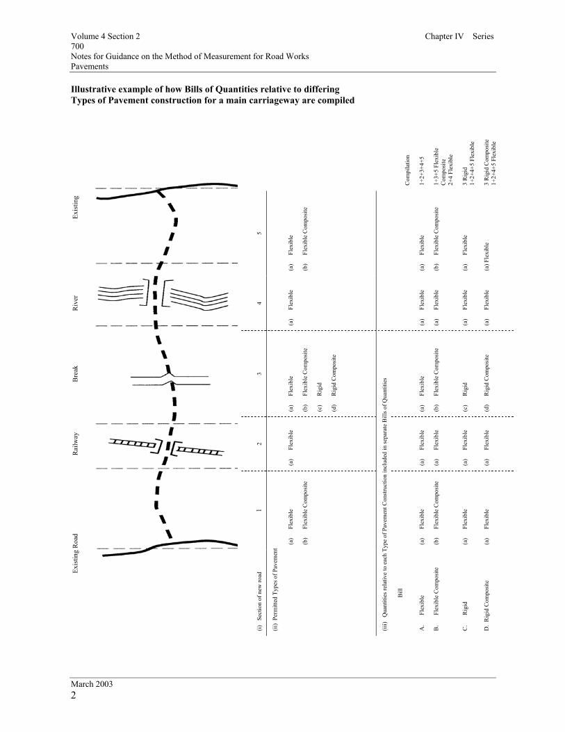
Illustrative example of how Bills of Quantities relative to differing Types of Pavement construction for a main carriageway are compiled
Com
pila
tion
1+2+
3+4+
5 1+
3+5
Flex
ible
C
ompo
site
2+
4 Fl
exib
le
3 R
igid
1+
2+4+
5 Fl
exib
le
3 R
igid
Com
posi
te
1+2+
4+5
Flex
ible
Exis
ting
5
(a)
Flex
ible
(b
) Fl
exib
le C
ompo
site
(a
) Fl
exib
le
(b)
Flex
ible
Com
posi
te
(a)
Flex
ible
(a
) Fle
xibl
e
Riv
er
4
(a
) Fl
exib
le
(a)
Flex
ible
(a
) Fl
exib
le
(a)
Flex
ible
(a
) Fl
exib
le
Bre
ak
3
(a)
Flex
ible
(b
) Fl
exib
le C
ompo
site
(c
) R
igid
(d
) R
igid
Com
posi
te
(a)
Flex
ible
(b
) Fl
exib
le C
ompo
site
(c
) R
igid
(d
) R
igid
Com
posi
te
Rai
lway
2
(a)
Flex
ible
(a
) Fl
exib
le
(a)
Flex
ible
(a
) Fl
exib
le
(a)
Flex
ible
1
(a)
Flex
ible
(b
) Fl
exib
le C
ompo
site
(a
) Fl
exib
le
(b)
Flex
ible
Com
posi
te
(a)
Flex
ible
(a
) Fl
exib
le
Exis
ting
Roa
d
(i)
Sect
ion
of n
ew ro
ad
(ii)
Perm
itted
Typ
es o
f Pav
emen
t
(iii)
Qua
ntiti
es re
lativ
e to
eac
h Ty
pe o
f Pav
emen
t Con
stru
ctio
n in
clud
ed in
sepa
rate
Bill
s of Q
uant
ities
Bill
A
. Fl
exib
le
B.
Flex
ible
Com
posi
te
C.
Rig
id
D.
Rig
id C
ompo
site

Volume 4 Section 2 Notes for Guidance on the Method of Measurement for Road Works Series 800
March 2003 1
Volume 4 home page
Series 800 is not taken up Volume 4 home page

Volume 4 Section 2 Notes for Guidance on the Method of Measurement for Road Works Series 900
March 2003 1
Volume 4 home page
Series 900 is not taken up Volume 4 home page

Volume 4 Section 2 Notes for Guidance on the Method of Measurement for Road Works Series 1000
March 2003 1
Volume 4 home page
Series 1000 is not taken up Volume 4 home page

Volume 4 Section 2 Chapter IV Series 1100 Notes for Guidance on the Method of Measurement for Road Works Kerbs, Footways and Paved Areas
March 2003 1
Series 1100: Kerbs, Footways and Paved Areas
Volume 4 home page Volume 4 home page
1 Steps The measurement of steps in this Series is intended for isolated steps and landings (eg steps to communication cabinets in cutting slopes). The Drawings should define within the Contract the extent of the steps and landings at each individual location and each complete set of steps and landings is measured individually at each location. Steps and landings incorporated in a structure should be measured in accordance with the appropriate Series of the MMRW. 2 Bituminous and Cement Bound Regulating Course Where the contract requires bituminous and cement bound regulating course in footways and paved areas a contract specific table should be prepared by the compiler and included within the Bill of Quantities immediately following the items of regulating course. This table should be in a similar format to that required for Series 700 – Pavements.
Volume 4 home page

Volume 4 Section 2 Chapter IV Series 1200 Notes for Guidance on the Method of Measurement for Road Works Traffic Signs and Road Markings
March 2003 1
Series 1200: Traffic Signs and Road Markings
Volume 4 home page Volume 4 home page
1 Road Studs Generally road studs will be chosen by the appropriate Overseeing Organisation to meet the specified requirements. The Contractor will submit details of the reflecting road studs he proposes to use in the works to the Overseeing Organisation for approval. 2 Removal of Road Markings The removal of road markings in connection with In-situ Recycling Processes is not required to be measured as this is already included with Series 700 Item Coverage paragraph 32(f). 3 Traffic Signal Installations - Network Cabling For the purposes of measurement of Traffic Signal Installations the network is defined as all cabling emanating from either an outstation transmission unit (O.T.U.), an outstation monitoring unit (O.M.U.) or an outstation monitoring and control unit (O.M.C.U.) and terminating at a location outside the limits of the site.
Volume 4 home page

Volume 4 Section 2 Notes for Guidance on the Method of Measurement for Road Works Series 1300
March 2003 1
Volume 4 home page
Series 1300 is not taken up Volume 4 home page

Volume 4 Section 2 Notes for Guidance on the Method of Measurement for Road Works Series 1400
March 2003 1
Volume 4 home page
Series 1400 is not taken up Volume 4 home page

Volume 4 Section 2 Notes for Guidance on the Method of Measurement for Road Works Series 1500
March 2003 1
Volume 4 home page
Series 1500 is not taken up Volume 4 home page

Volume 4 Section 2 Notes for Guidance on the Method of Measurement for Road Works Series 1600
March 2003 1
Volume 4 home page
Series 1600 is not taken up Volume 4 home page

Volume 4 Section 2 Chapter IV Series 1700 Notes for Guidance on the Method of Measurement for Road Works Structural Concrete
March 2003 1
Series 1700: Structural Concrete
Volume 4 home page Volume 4 home page
1 Curved Formwork The items for curved formwork in paragraph 13, Group II, Features 5, 6 and 7 are to be used for any formwork that is required to produce a permanent curved finish to the concrete. Formwork curved or hogged in construction before the placement of concrete and designed to achieve a permanent flat finish shall not be measured as curved. Formwork required to produce curved falls and cambers is measured as curved formwork. 2 Finishes to Concrete Unformed finishes (U1 to U5 etc.) should not be measured. They are covered by the item coverage in paragraph 4 of Series 1700. 3 Underbridges and Footbridges When underbridges up to 8 m span and footbridges are designed by the Contractor they are to be measured under Series 2500.
Volume 4 home page

Volume 4 Section 2 Notes for Guidance on the Method of Measurement for Road Works Series 1800
March 2003 1
Volume 4 home page
Series 1800 is not taken up Volume 4 home page

Volume 4 Section 2 Notes for Guidance on the Method of Measurement for Road Works Series 1900
March 2003 1
Volume 4 home page
Series 1900 is not taken up Volume 4 home page

Volume 4 Section 2 Chapter IV Series 2000 Notes for Guidance on the Method of Measurement for Road Works Waterproofing for Concrete Structures
March 2003 1
Series 2000: Waterproofing for Concrete Structures
Volume 4 home page Volume 4 home page
1 Additional Protective Layers The Specification requires an additional protective layer, in the form of a red tinted bituminous protection, to be laid on those areas of any waterproofing system that are to be overlaid with hot rolled surfacing materials. The Drawings should show these areas and also other areas that are to be provided with other types of additional protective layers, such as a protective concrete screed. These protective layers are included in the item coverage for waterproofing and are not measured separately.
Volume 4 home page

Volume 4 Section 2 Notes for Guidance on the Method of Measurement for Road Works Series 2100
March 2003 1
Volume 4 home page
Series 2100 is not taken up Volume 4 home page

Volume 4 Section 2 Notes for Guidance on the Method of Measurement for Road Works Series 2200
March 2003 1
Volume 4 home page
Series 2200 is not taken up Volume 4 home page

Volume 4 Section 2 Notes for Guidance on the Method of Measurement for Road Works Series 2300
March 2003 1
Volume 4 home page
Series 2300 is not taken up Volume 4 home page

Volume 4 Section 2 Chapter IV Series 2400 Notes for Guidance on the Method of Measurement for Road Works Brickwork, Blockwork and Stonework
March 2003 1
Series 2400: Brickwork, Blockwork and Stonework
Volume 4 home page Volume 4 home page
1 General The item coverage applicable to removing from store and relaying brickwork, blockwork and stonework includes for replacing items damaged during removal, cleaning, transportation and modifications. The requirements for this work and the expected recovery of second hand materials should be detailed in the Contract. Modifications of which the Contractor was not informed at the time of tender are not covered by this item coverage.
Volume 4 home page

Volume 4 Section 2 Notes for Guidance on the Method of Measurement for Road Works Series 2500
March 2003 1
Volume 4 home page
Series 2500 is not taken up Volume 4 home page

Volume 4 Section 2 Notes for Guidance on the Method of Measurement for Road Works Series 2600
March 2003 1
Volume 4 home page
Series 2600 is not taken up Volume 4 home page

Volume 4 Section 2 Notes for Guidance on the Method of Measurement for Road Works Series 2700
March 2003 1
Volume 4 home page
Series 2700 is not taken up Volume 4 home page

Volume 4 Section 2 Notes for Guidance on the Method of Measurement for Road Works Series 2800
March 2003 1
Volume 4 home page
Series 2800 is not taken up Volume 4 home page

Volume 4 Section 2 Notes for Guidance on the Method of Measurement for Road Works Series 2900
March 2003 1
Volume 4 home page
Series 2900 is not taken up Volume 4 home page

Volume 4 Section 2 Notes for Guidance on the Method of Measurement for Road Works Series 3000
March 2003 1
Volume 4 home page
Series 3000 is not taken up Volume 4 home page

Chapter II
General Principles

General Principles Method of Measurement
1 a
The Method of Measurement is intended for use for road contracts with any form of contract. Amendments may be required for particular Contract Conditions.
b
The Method of Measurement, is based on the Specification for Road Works and of the Road Construction Details published as Volume 1 and Volume 3 of the Manual of Contract Documents for Road Works and on the principle that full details of construction requirements are provided in the Contract. Additions or amendments to the Specification for Road Works or the Road Construction Details which are not adequately covered by the Method of Measurement will necessitate appropriate amendment to suit. Provision is made in Chapter III Preambles to Bill of Quantities, “Amendments to the Method of Measurement” to accommodate such amendments.
Bill of Quantities
2 a
In the Bill of Quantities the sub-headings and item descriptions identify the work covered by the respective items read in conjunction with the matters listed against the relevant marginal headings “Item coverage” in Chapter IV of the Method of Measurement, Chapter III Preambles to Bill of Quantities and amendments. The nature and extent of the work to be performed is to be ascertained by reference to the Drawings, Specification and Conditions of Contract.
b
Items included in the Bill of Quantities for work to be executed or goods, materials or services to be supplied by a Nominated Subcontractor shall be followed by separate items for: (i) Labours in connection therewith in the form of a lump sum. (ii) All other charges and profit in connection therewith in the form of a percentage.
Itemization - Groups and Features
3
Each item description is to be consistent with and be compounded from one or more of the Groups listed under the marginal headings “Itemisation” within the Series of Chapter IV of the Method of Measurement incorporating amendments introduced in the Preambles to the Bill of Quantities. An item description may contain Features from as many Groups as necessary to identify the work required, but may include only one Feature from any one Group.
Items in the Bill of Quantities
4
The Bill of Quantities, unless expressly stated otherwise in the Contract is to contain all those items compounded in accordance with the foregoing paragraph 3 required to comprise the Works (apart from Provisional Sums and Prime Cost Items which may be required).

Chapter III
Preparation of Bill of Quantities
(including Preambles to Bill of Quantities)

Preparation of Bill of Quantities Sub-division of Bill of Quantities
1
The Bill of Quantities is to be divided as appropriate into separate levels of identification, in the sequence set down in Table 1.
Quantities
2
Quantities shall be expressed in whole numbers except for units of measurement of tonnes and hectares in which case the quantities shall be to three decimal places. The following abbreviations shall be used for the units of measurement: Unit Abbreviation Unit Abbreviation millimetre mm sum sum metre M number no square millimetre
mm² hour hr
square metre M² week wk hectare ha item iem cubic metre M³ vehicle week v.wk kilogram kg man hour man hr tonne T vehicle day v. day
Units of Measurement
3
day day operative day op. day

Special Preliminary Items
4 Provision is made in Table 1 for the inclusion of “Special Preliminary” items in the Bill of Quantities. “Special Preliminary” items are not included in Chapter IV Units and Method of Measurement as their use is intended to be restricted and particular to a given Contract. “Special Preliminary” items shall not be used for Temporary Works, cofferdams, accesses, advance operations and the like unless the work or operation is unusual in relation to the Works, and:
a) the magnitude of such work, not separately measured, is such as to be disproportionately high in cost in relation to the measured work with which it is associated; or
b) an operation, not separately measured, is required to be executed far in
advance or after the main measured operation to which it relates. The inclusion of “Special Preliminary” items in a Contract shall be entirely at the discretion of the Overseeing Organisation. Whether a “Special Preliminary” item is included in the Bill of Quantities or not shall in no way relieve the Contractor of his obligations under the Contract.

Alternative Types of Pavement
5 Where the Contract provides for the tenderer to select the Type of Pavement to be constructed from a range of alternatives a separate Bill of Quantities is to be provided within Series 600 : Earthworks, of the Roadworks General Bill; and Series 700 : Pavements, of the Main Carriageway, Interchanges and Side Roads Bills as appropriate, for each Type of Pavement permitted by the Contract. Each of the individual Bills of Quantities within Series 600 of the Roadworks General Bill and in Series 700 of the Main Carriageway, Interchanges and Side Roads Bills as appropriate, is to be based on the thinnest pavement permitted by the Contract for the particular Type of Pavement to which it refers. Immediately preceding the separate sets of alternative Bills in Series 600 : Earthworks and Series 700: Pavements respectively an Index (Table 2) is to be provided of the Types of Pavement permitted by the Contract. Provision is to be made for only the one Bill of Quantities in Series 600 of the Roadworks General Bill and in Series 700 of the Main Carriageway, Interchanges and Side Roads Bills as appropriate which relates to the Type of Pavement elected to be constructed by the Contractor, to be priced and included in the Tender Total.
Alternative Types of 6 Safety Fence
Where the Contract provides for the tenderer to select either wire rope safety fence or tensioned corrugated beam safety fence to be constructed over given lengths, separate Bills of Quantities are to be provided containing alternative types of safety fence for the lengths in question. These Bills of Quantities are to be included within Series 400: Safety Fences, Safety Barriers and Pedestrian Guardrails. Immediately preceding the separate alternative Bills in Series 400 an Index (Table 3) is to be provided for the alternative types of safety fence permitted by the Contract. Provision is to be made for only the one Bill of Quantities in Series 400 of the Roadworks General Bill which relates to the type of safety fence elected to be constructed by the Contractor to be priced and included in the Tender Total.

Structures Where a 7 Choice of Designs is Offered
Where the Contract provides for a structure designed by the Contractor to be constructed as an alternative to the structure which has been designed by the Overseeing Organisation, a separate Bill of Quantities is to be provided for each of the two construction procedures permitted by the Contract. Each of the two individual Bills of Quantities is to be provided in accordance with the various Chapters and Series of the Method of Measurement for all the works contained within the Designated Outline (with the exception of those works scheduled as not to be included). For the structure designed by the Contractor the Bill of Quantities is to comprise a single item in accordance with Series 2500. The Bill for the structure designed by the Overseeing Organisation is to be compiled in accordance with the appropriate Series. Those works scheduled as not to be included in either of these alternative Bills of Quantities shall be included by the Overseeing Organisation in other Bills compiled in accordance with the appropriate Series. Provision is to be made for only the one Bill of Quantities which relates to the form of construction elected to be constructed by the Contractor to be priced and included in the Tender Total. Immediately preceding the separate alternative Bills of Quantities an Index (Table 4) is to be provided for the alternative forms of construction permitted by the Contract.
Structures Designed 8 by the Contractor
Where the Contract provides only for a structure designed by the Contractor to be constructed a Bill of Quantities comprising a single item for all the works within the Designated Outline (with the exception of those works scheduled as not to be included) is to be provided in accordance with Series 2500. Those works scheduled as not to be included in this single item are to be included by the Overseeing Organisation in other Bills compiled in accordance with the appropriate Series. Earthworks within the Designated Outlines shall not be included in the Earthworks Schedules.

Landscape and Ecology
9 Where the Contract includes for Landscape and Ecology a separate Bill of Quantities shall be provided within the Roadworks Bill as set down in Table 1. Payments for new planting, seeding and turfing measured in accordance with Series 3000 paragraphs 6 to 13 inclusive shall be subject to staged payments as set out in Table 5 which shall be completed by the compiler. This table shall be inserted immediately preceding the Collection page for the separate Bill of Quantities for Landscape and Ecology.
Preambles to Bill of Quantities 10
The matters set out under the heading “Preambles to Bill of Quantities” (1-18) hereafter are always to be included as a Preamble to the Bill of Quantities. Additional numbered Preambles may be included as necessary. Amendments to the Method of Measurement are to follow paragraph 20 (see notes to compiler).

Table 1
LEVEL 1
DIVISION
LEVEL 2
CONSTRUCTION HEADING
LEVEL 3
MMRW SERIES HEADINGS
NOTES
(i) Preliminaries Preliminaries 100 Preliminaries Special Preliminaries Should be inserted under level 3
(ii) Roadworks Roadworks general 200 Site Clearance 300 Fencing 400 Safety Fences, Safety Barriers and
pedestrian Guardrails 600 Earthworks
Goetechnics and Hedgebanks and the like should be inserted under level 3 Series 600
Main Carriageway 500 Drainage and Service Ducts 700 Pavements 1100 Kerbs, Footways and Paved Areas
Police observations platforms, cycle tracks, and the like should be inserted under level 3 Series 1100
Interchanges 500 Drainage and Service Ducts 700 Pavements
Cycle tracks and the like should be inserted under level 3 Series 1100
Side Roads 500 Drainage and Service Ducts 700 Pavements 1100 Kerbs, Footways and Paved Areas
Cycle tracks and the like should be inserted under level 3 Series 1100
Signs, Motorway Communications and Lighting
1200 Traffic Signs and Road Markings 1300 Road Lighting Columns, Brackets and CCTV Masts 1400 Electrical Work for Road Lighting and
Traffic Signs 1500 Motorway Communications
Landscape and Ecology (05/01)
3000 Landscape and Ecology

LEVEL 1
DIVISION
LEVEL 2
CONSTRUCTION HEADING
LEVEL 3
MMRW SERIES HEADINGS
NOTES
DIVISION SUB-DIVISION (iii) Structures Structure in form
of Bridge or Viaduct; Name or Reference
Special Preliminaries Special Preliminaries should be inserted as a separate construction heading under level 2
Piling 1600 Piling and Embedded Retaining walls
Substructure – End Supports
500 Drainage and Ducts 600 Earthworks 1100 Kerbs, Footways and Paved
Areas 1700 Structural Concrete 1800 Structural Steelwork 1900 Protection of Steelwork. Against Corrosion 2300 Bridge Expansion Joints and
Sealing of Gaps 2400 Brickwork, Blockwork and Stonework
Substructure- Intermediate Supports Substructure – Main Span Substructure – Approach Spans
As for End Supports To include piers and columns

LEVEL 1
DIVISION
LEVEL 2
CONSTRUCTION HEADING
LEVEL 3
MMRW SERIES HEADINGS
NOTES
DIVISION SUB-DIVISION Superstructure – Main Span
Superstructure – Approach Spans Superstructure – Arch Ribs
500 Drainage and Service Ducts 1700 Structural Concrete 1800 Structural Steelwork 1900 Protection of Steelwork
Against Corrosion 2100 Bridge Bearings 2300 Joints and Sealing of Gaps 2400 Brickwork, Blockwork and
Stonework
Finishings 400 Safety Fences, Safety Barriers And Pedestrian Guardrails
600 Earthworks 700 Pavements 1100 Kerbs, Footways and Paved Areas 2000 Waterproofing for Structures 2200 Parapets 2400 Brickwork, Blockwork and Stonework
Pavements, footways and the like to be included here if no Roadworks Bills of Quantities
Retaining Wall, Culvert Subway, Gantry, Large Headwall, Gabion Wall, Diaphragm Wall, Pocket Type Reinforced Brickwork Retaining Wall and the like; Name or Reference
Special Preliminaries Special Preliminaries should be inserted as a separate construction heading under level 2

LEVEL 1
DIVISION
LEVEL 2
CONSTRUCTION HEADING
LEVEL 3
MMRW SERIES HEADINGS
NOTES
DIVISION SUB-DIVISION Main Construction 500 Drainage and Service Ducts
600 Earthworks 1100 Kerbs, Footways and Paved
Areas 1600 Piling and Embedded
Retaining Walls 1700 Structural Steelwork 1800 Structural Steelwork 1900 Protection of Steelwork
Against Corrosion 2300 Bridge Expansion Joints and
Sealing of Gaps 2400 Brickwork, Blockwork and Stonework
Finshings 400 Safety Fences, Safety Barriers And Pedestrian Guardrails
600 Earthworks 700 Pavements 1100 Kerbs, Footways and Paved
Areas 2000 Waterproofing for Structures 2200 Parapets 2400 Brickwork, Blockwork and Stonework
Pavements, Footways and the like to be included here if no Roadworks Bill of Quantities

LEVEL 1
DIVISION
LEVEL 2
CONSTRUCTION HEADING
LEVEL 3
MMRW SERIES HEADINGS
NOTES
DIVISION SUB-DIVISION Structure Designed by the overseeing Organisation; Name or Reference
(iv) Structures Where a Choice of Designs is Offered
Structure Designed by the Contractor, Name or Reference
To include works within Designated outlines with the exception of works scheduled as not to be included. This division is not to be used where the Contract provides only for a structure designed by the Contractor
(v) Structures Designed by the Contractor
Structure: Name or Reference
To include works within Designated Outlines with the exception of works scheduled as not to be included
(vi) Service Areas Roadworks Structures
(vii) Maintenance Compounds Roadworks Structures
To comply with the principles set down above for Roadworks and Structures
(viii) Accommodation Works Interest; Name or Reference (ix) Works for Statutory or other Bodies Body; Name or Reference To comply with the
principles set down above for Roadworks and Structures
(x) Daywork Daywork
(xi) PC and Provisional Sum PC and Provisional Sum To include PC and Provisional sums not allocated to a particular construction heading

Table 2
(This Table 2 is an example of the introduction and index to be inserted as a separate page immediately preceding each set of the separate Bills of Quantities included within Series 600: Earthworks in the Roadworks General Bill and Series 700: Pavements in the main Carriageway, Interchanges and Side Roads Bills, to cover the alternative Types of Pavement included in the Contract.) # ( Bill No………..Roadworks General – Series 600: Earthworks) * ( Bill No…………Main Carriageway – Series 700: Pavements) * ( Bill No…………..Interchanges – Series 700: pavements) * ( Bill No…………… Side Roads – Series 700: Pavements A separate Bill of Quantities is provided for each of the Types of Pavement permitted by the Contract. Notwithstanding the provision paragraph 4 of the Preambles to the Bill of Quantities, the tenderer shall price, extend and carry to the collection of # ( bill No…Series 600 : earthworks) * (Bill No … Series 700: Pavements only that Bill of Quantities appropriate to the Type of Pavement he has elected to construct . The tenderer shall price the Bill of Quantities in Series 600 : Earthworks corresponding to the Type of Pavement he prices in Series 700 : Pavements which he has elected to construct.
Index Type of Pavement Bill No. Page(s) Flexible # ( 6A) * (7A)
Flexible Composite # ( 6B) * (7 B)
Rigid # ( 6 C) *(7 C)
(# Include when Index is for Series 600: Earthworks in Roadworks General Bill) (* Include when Index is for Series 700: Pavements in Main Carriageway, interchanges and Side Roads Bills as Appropriate)
Table 3

(This Table 3 is an example of the introduction and index to be inserted as a separate page immediately preceding the separate Bills of Quantities included within Series 400: Safety Fences , Safety Barriers and Pedestrian Guardrails in the Roadwork’s general Bill to cover the4 alternative types of safety fence included in the Contract.)
(bill No……….Roadworks General – Series 400: Safety Fence, Safety Barriers and Pedestrian Guardrails)
A separate Bill of Quantities is provided to include for each of the alternative types of safety fence for the lengths permitted by the Contract. Notwithstanding the provisions of paragraph 4 of the Preambles to the Bill of Quantities, the tenderer shall price, extend and carry to the collection of Bill 4 : Safety Barriers and Pedestrian Guardrails only that Bill of Quantities appropriate to the type of safety fence he has elected to construct.
Index Safety Fence Type Bill No. Page(s) Beam 4A Wire Rope 4B (The lengths of safety fence for which no alternative is permitted are to be included in both the beam and the wire rope Bills).
Table 4
(This Table 4 is an example of the introduction and index to be inserted as a separate page immediately preceding the separate Bills of Quantities included within the Bill for Structures Where a Choice of Designs is Offered ( as defined under paragraph 7 of the preparation under paragraph 7 of the preparation of Bill of Quantities.)
Bill No……….Structures Where a Choice of Designs is Offered A separate Bill of Quantities is provided for each of the two construction procedures permitted by the Contract. Notwithstanding the provisions of paragraph 4 of the Preambles to Bill of Quantities, the tenderer shall price, extend and carry to the collection of Bill No…:Structures Where A Choice of Designs is Offered, only that Bill of Quantities appropriate to the form of construction he has elected to construct.
Index Type of Structure Structure No. Bill No. Page(s) Structure Designed by the Overseeing Organisation …A Structure Designed by the Contractor …B (Repeat for each Structure)
Table 5

(This Table 5 is an example of the Staged Payment Scheduled for new Planting, Seeding and Turfing wok to be inserted as a separate page immediately preceding the Collection Page for the separate Bill of Quantities for Series 3000 – Landscape and Ecology.) Bill No……Series 3000 – Landscape and Ecology The following Staged Payments Schedule is to used for the assessment of payments for work included in the Bill of Quantities in respect of new Planting. Seeding and Turfing measured in accordance with Series 3000 paragraph 6 to 13 inclusive. Activity Percentage to be paid on
planting in accordance with Note 1 below. [ To be inserted by compiler]
Percentage to be paid in respect of post-planting works in accordance with Note 2 below. [To be inserted by Compiler]
Total
Grass seeding: High Frequency Cuts Medium Frequency cuts Low Frequency Cuts Minimal Frequency Cuts
100% 100% 100% 100%
Wildflower Seeding 100% Turfing 100% Shrubs including transplants
100%
Trees including transplants
100%
Wildflower Plants 100% Hedge Plants 100% Emergent, Marginal and Aquatic Plants
100%
Bulbs: In grassed areas In beds
100% 100%
Note 1: The percentage entered in this column shall be the proportion of the rates and prices in the Bill of
Quantities for those item which become due to the Contractor upon the completion of the particular operation.
Note 2: The percentage entered in this column shall be in proportion of the rates and prices in the Bill of Quantities in respect of post-planting works required to be carried out over the remainder of the
Contract Period. This proportion shall be divided equally over the period of the contract remaining (in months) after the specific planting has taken place to give a ‘periodic value’ in respect of post-planting works. Notwithstanding the contract payment terms this ‘periodic value’ shall be paid on accrual at ..[to be inserted by the Compiler]..monthly intervals with any balance due on completion of the whole of the Works.


MM
RW
SER
IES
HEA
DIN
GS
1600
Pili
ng a
nd E
mbe
dded
Ret
aini
ng w
alls

MM
RW
SER
IES
HEA
DIN
GS

MM
RW
SER
IES
HEA
DIN
GS

MM
RW
SER
IES
HEA
DIN
GS
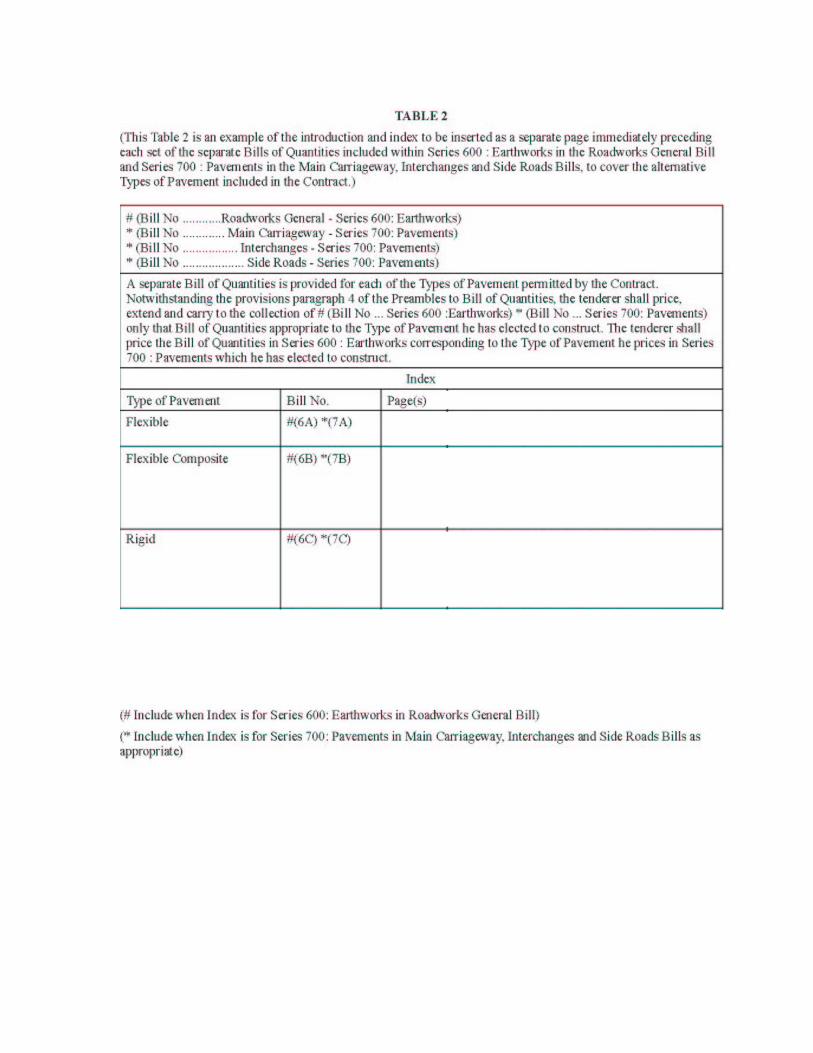


A
…B


Preambles to Bill of Quantities General Directions 1 The Bill of Quantities has been prepared in accordance with the Method of
Measurement for Road Works. 2 In the Bill of Quantities the sub-headings and item descriptions identify the work covered by the respective items, read in conjunction with the matters listed against the relevant marginal headings “Item coverage” in Chapter IV of the Method of Measurement for Road Works, these Preambles and the amendments to the Method of Measurement immediately following these Preambles. The nature and extent of the work is to be ascertained by reference to the Drawings, Specification and Conditions of Contract. The rates and prices entered in the Bill of Quantities shall be deemed to be the full inclusive value of the work covered by the several items including the following, unless expressly stated otherwise: (i) Labour and costs in connection therewith. (ii) The supply of materials, goods, storage and costs in connection therewith
including delivery to Site. Taking delivery of materials and goods supplied by others, unloading, storage, and costs in connection therewith.
(iii) Plant and costs in connection therewith. (iv) Fixing, erecting and installing or placing of materials and goods in position. (v) Temporary Works. ] (vi) The effect on the phasing of the Works or any element of the Works to the
extent set forth or reasonably implied in the documents on which the tender is based.
(vii) General obligations, liabilities and risks involved in the execution of the
Works set forth or reasonably implied in the documents on which the tender is based.
(viii) Establishment charges, overheads and profit. (ix) Waste. (x) Testing carried out by the Contractor in accordance with the particular
requirements of Appendix 1/5 including supplying results of tests, reports and certificates.
(xi) Supply and delivery of samples to the Overseeing Organisation in
accordance with the particular requirements of Appendix 1/6. (xii) Checking, inspecting, examining, measuring and verifying goods,
materials and workmanship including supplying results, reports and certificates.
(xiii) Attendance and transport for sampling and testing carried out by the
Overseeing Organisation. (xiv) Complying with Quality Assurance requirements of the contract and

providing certificates of conformity. (xv) Preparation and supply of detailed working drawings. (xvi) Awaiting approvals and consent. (xvii) Where stipulated complying with the particular requirements of Appendix 1/24.
Measurement 3 (i) The measurement of work shall be computed net from the dimensions stated in the Contract unless otherwise
stated in the Method of Measurement. (ii) Where the tender documents specify the Type of Pavement to be
constructed then the measurement of work shall be based upon the thinnest pavement construction and surfacing over structures permitted by the Contract for that Type of Pavement. Where the tender documents provide for the Contractor to select the type of safety fence, pavement or buried structure (where the structure is not within Designated Outlines) to be constructed then the measurement of all work in each area so affected shall be based upon the thinnest pavement construction and surfacing over structures permitted by the Contract in that area for the particular type of safety fence, pavement or buried structure the Contractor has elected to construct.
Pricing of Items 4 Each individual item shall have a rate or price entered against it. Rates and prices shall be expressed to two decimal places.
Alternative Specified Materials, Designs and Options Within Types of Pavement
Where in the Contract a choice of alternatives is permitted:
(i) the description billed and the rates and prices inserted shall be deemed to cover any of the permitted alternative materials or designs the Contractor may elect to use;
(ii) and where separate Bills of Quantities are provided within Series
600: Earthworks for each Type of Pavement permitted by the Contract the rates and prices inserted in respect of the earthworks for the particular Type of Pavement shall be deemed to cover the earthworks for any inherent permitted option within the Type of Pavement elected to be constructed by the Contractor;
(iii) and where separate Bills of Quantities are provided within Series
700: Pavements for each Type of Pavement permitted by the Contract the rates and prices inserted in respect of the particular Type of Pavement shall also be deemed to cover any inherent permitted option within the Type of Pavement elected to be constructed by the Contractor.
In all cases the rates and prices inserted in all Series of the Bill of Quantities shall be deemed to include for any adjustments of work content, rates, costs and the like occasioned by the choice of alternatives elected to be used or constructed by the Contractor.
Privately and Publicly Owned Services or Supplies
6 The information in the Contract as to the whereabouts of existing services and mains is believed to be correct but the Contractor shall not be relieved thereby of his obligations under the Contract. The Contractor shall include in his rates and prices for locating and taking measures for the support and full protection of pipes, cables and other apparatus during the progress of

the Works, obtaining the written consent of the appropriate authority to interrupt the service or supply and for keeping the Overseeing Organisation informed of all arrangements he makes with the owners of privately owned services or supplies, Statutory Undertakers and Public Authorities as appropriate.
Labours 7 Labours in connection with Nominated Sub-contractors shall include:
(i) in the case of work or services executed - for affording the use of existing working space, access, temporary roads, erected scaffolding, working shelters, staging, ladders, hoists, storage, latrines, messing, welfare and other facilities existing on Site and the provision of protection, water, electricity for lighting and clearing away rubbish and debris arising from the work;
(ii) in the case of goods, materials or services supplied - for taking
delivery, unloading, storing, protecting and returning crates, cartons and packing materials.
Roadworks Overall Requirements
8 The Contractor shall allow in his rates and prices for complying with requirements in respect of pavement construction, horizontal alignments, surface levels and surface regularity of pavement courses, dealing with changes in weather conditions, use of surfaces by traffic and construction plant, and general requirements for sub-bases and base courses.
Work Within and Below Non-tidal Open Water or Tidal Water
9 The Contractor shall allow in his rates and prices for taking measures required to execute work within and below non-tidal open water or tidal water. The Contractor shall include in his rates and prices for any investigations to ascertain actual boundaries, surface levels and ranges affected by non-tidal open water or tidal water.
Dealing with Flow 10 The Contractor shall allow in his rates and prices for taking measures to deal with the existing flow of water, sewage and the like.
Reimbursement of Fees, Overseeing Organisation’s Telephone Calls
11 The Contractor will be reimbursed the actual price paid by the Contractor in respect of:
(i) fees, rates and taxes - the sums certified as properly repayable to the Contractor in accordance with the Contract;
(ii) Overseeing Organisation’s telephone calls - telephone calls charged to the number or numbers allocated to the Overseeing Organisation. Any other cost, charge or expense in respect of these
items shall be allowed for in the rates and prices for temporary accommodation.
Site Limitations and Constraints
12 The Contractor shall allow in his rates and prices for complying with any limitations and constraints on the use of the Site.
Hard Material 13 For the purposes of the Contract the following are designated as Hard Material in accordance with Chapter 1 Definitions, paragraph 1(i)(i):
(a) .......* strata; (b) those deposits designated by limits shown on the Drawings; (c) existing pavements, footways, paved areas (but excluding unbound
materials) and foundations in masses in excess of 0.20 cubic metres.

Equivalent Products and Materials
14 Where the Contractor offers an equivalent product or material in place of the one identified or specified, then the rates and prices in the Bill of Quantities shall be deemed to include for all the obligations and costs associated with the incorporation of the equivalent into the Works, including design, provision of data and drawings, certificates, awaiting acceptance, resubmissions and modifications and amendments to the Works. Volume 4 home page Unless specifically stated to the contrary in the Contract the measurement of the Works affected by the incorporation of the equivalent products and materials shall be based on the Tender documents and not on the Works as amended and completed to incorporate the equivalent products and materials.
Permanent Works Designed by the Contractor
15 Where the Contract requires part(s) of the Permanent Works to be designed by the Contractor, the rates and prices in the Bill of Quantities shall include for all the obligations and costs associated with the incorporation of the Contractor’s design into the Works, including design, provision of data and drawings, certificates, awaiting approvals, resubmissions and modifications and amendments to the Works. Additionally the rates and prices in the Bill of Quantities shall include for the costs of all testing and sampling to be carried out by the Contractor in respect of workmanship, goods and materials incorporated into the Works or to prove the Contractor’s design.
Structures Designed by the Contractor
16 In respect of each priced Bill for a structure designed by the Contractor, the Contractor shall prepare a priced schedule of quantities. This priced schedule shall be prepared in accordance with the relevant Chapters and Series of the Method of Measurement and submitted to the Overseeing Organisation for acceptance. The quantities, rates and prices in the priced schedule of quantities shall in each case, when extended and totalled, give the amount entered in the priced Bill of Quantities against the item for the relevant structure designed by the Contractor. The priced schedule of quantities shall only be used for Payment Applications and for the valuation of variations ordered under the Contract in connection with structures designed by the Contractor. Unless specifically stated to the contrary in the Contract the measurement of the Works affected by the incorporation of the Contractor’s design shall be based on the Tender documents and not on the Works as amended and completed to incorporate the Contractor’s design. The parts of the Works included by the Contractor in the priced schedule of quantities shall include all the parts of the Works within the Designated Outline except those designed and scheduled by the Overseeing Organisation as not to be included.

Testing 17 Testing as paragraph 2(x) above, is in respect of tests to be carried out by the Contractor to verify workmanship, goods and materials incorporated into the permanent works and testing of the permanent works in order to prove the Overseeing Organisation’s design as set out in Appendix 1/5. Checking, inspecting, examining, measuring and verifying goods, materials and workmanship incorporated in the permanent works, as paragraph 2(xii) above, is in respect of other operations set forth or reasonably implied in the Contract to be carried out by the Contractor to demonstrate compliance with the particular requirements of the Contract, or to prove the Overseeing Organisation’s design where not separately listed in Appendix 1/5, but excluding trial erection of structural steelwork which shall be measured separately in accordance with Series 1800. Procedural trials, trial panels and trial areas required to be carried out or constructed as separate operations in advance of the permanent works in order to verify goods, materials and workmanship shall not be measured separately but are included within the item coverage for the relevant Series. Testing of existing structures and other investigative works shall be individually measured within the relevant Series.
Landscape and Ecology
18 The rates and prices inserted in the Bill of Quantities for new Planting, Seeding and Turfing measured in accordance with Volume 4 – Series 3000 include for all post-planting maintenance work required to be carried out in accordance with the Specification and the relevant Appendices. In order to properly reflect the scope and duration of the planting and postplanting requirements a series of staged payments for the various items of planting, seeding and turfing will be made in accordance with the Staged Payments Schedule. The Staged Payments Schedule is to be inserted in the Bill of Quantities immediately preceding the collection page for Landscape and Ecology and shall be used for assessing payments due to the Contractor in accordance with the Contract.
†Amendments to the Method of Measurement
19 For the purposes of the Contract the Method of Measurement for Highway Works is amended in accordance with the pages immediately following.
Volume 4 home page The Preambles to Bill of Quantities (duly completed) must be reproduced unaltered and bound in the Bill of Quantities. * To be completed by compiler as appropriate. † Where amendments to Chapter IV of the Method of Measurement are required in accordance with paragraph 1(b) of Chapter II, General Principles, this preamble should be the last numbered preamble and inserted immediately prior to the amendments.] Volume 4 home page

Volume 4 Section 2 Chapter IV Series 100 Notes for Guidance on the Method of Measurement for Road Works Preliminaries
Amendment – March 2003 1
Series 100: Preliminaries
Volume 4 home page
1 General These Notes for Guidance use generic terms and compilers should refer to the proposed particular Form of Contract being used for derivation of contract specific terminology. 2 Privately and Publicly Owned Services and Supplies Particulars of the services and supplies affected by the Permanent Works and any preliminary arrangements for alterations by the owner or authority responsible should be detailed in Appendix 1/16 of the Specification but not included in Items or Sums in the Bill of Quantities, apart from any permanent works for the alterations which are to be provided by the Contractor, for example ducts. Charges by the owner or authority responsible for these alterations will be paid by the Overseeing Organisation after scrutiny. Any alterations to services and supplies required for the Contractor’s temporary works, diversions and the like are the responsibility of the Contractor and are deemed to be covered by the rates and prices in the Bill of Quantities. 3 Maintenance of Highways Appendix 1/17 of the Specification specifies those maintenance functions which will be the responsibility of the Contractor within defined physical limits and time periods. The work scheduled in this Appendix is covered by the rates and prices inserted by the Contractor in the Bill of Quantities. 4 Contraflows (Traffic Safety and Management) There are three possible methods by which contraflows can be planned and designed:
(a) full proposals drawn up by the Overseeing Organisation; (b) outline proposals drawn up by the Overseeing Organisation and
completed by the Contractor; (c) full proposals drawn up by the Contractor.
Requirements under methods (a) or (b) should be scheduled in Appendix 1/17. Method (c) will be deemed as Contractor’s temporary works to be included in the contraflow item.

Volume 4 Section 2 Chapter IV Series 100 Notes for Guidance on the Method of Measurement for Road Works Preliminaries
Amendment – March 2003 2
It is recommended that the contraflow item is always included when traffic management is required thus allowing for Contractor’s proposals as described in method (c) above. Volume 4 home page 5 Temporary Diversion for Traffic The MMRW allows for temporary diversions for traffic to be measured as follows:
(a) Specific Locations - These may include those where, in the opinion of the compiler, the diversionary work is likely to be complicated, expensive, or its impact on or disruption of the Works is likely to be substantial. The description should include the appropriate reference from Appendix 1/18 of the Specification.
(b) Omnibus Item - This should include all diversions of a minor nature scheduled in Appendix 1/18 of the Specification. The omnibus item should not include in its description the references from Appendix 1/18 of the Specification.
(c) A separate omnibus item should always be provided for all diversions at locations proposed by the Contractor.
6 Damage to the Roadway The responsibility for repairing damage to roadways rests with the Contractor unless stated otherwise in Appendix 1/17 or 1/18. The compiler should check whether or not the Conditions of Contract requires the Contractor to insure and indemnify the Overseeing Organisation against loss, damage and claims. If so, this is covered by Preamble 2 (vii) to the Bill of Quantities. 7 Information Boards and Driver Information Signs The items in the Bills of Quantities for Information Boards shall only be in respect of those Information Boards detailed in Appendix 1/21 to the Specification. The Information Boards should not be confused with Driver Information Signs which, when required, will be detailed in Appendix 1/17 to the Specification and are included in the Item Coverage for Traffic Safety and Management.

Volume 4 Section 3 Series 200 Library of Standard Item Description for Road Works Site Clearance
March 2003 1
Series 200: Site Clearance
Item Root Narrative Unit Site Clearance 1 General site clearance ha
2 General site clearance area 1* ha
3 Demolition of building or structure 1* item
4 Demolition of group of buildings or structures 1* item
5 Partial demolition of individual structures 1* item
Take Up or Down and Set Aside for Re-use or Remove to Store or Tip off Site 6 Take up or down 2*3*4* m3
7 Take up or down 2*5* paving 6* m2
8 Take up or down 2*4* brickwork 6* m2
9 Take up or down 2*7*19* m
10 Take up or down 2*8*9* safety fencing 11* m
11 Take up or down 2*10*4*13* m
12 Take up or down 2*12* fence 13* m
13 Take up or down 2*14*4*19* m
14 Take up or down 2*15*16* m
15 Take up or down 2*17*18*19* no
16 Take up or down 2*20* no
Group Variables 1* (i) etc =[stated reference] 2* (i) =and set aside for reuse (ii) =and remove to store off Site
(iii) =and remove to tip off Site
3* (i) =blockwork (ii) =stonework 4* (i) etc =[stated Type] 5* (i) =precast concrete slab (ii) =stone flag (iii) =brick (iv) =cobble
Volume 4 Section 3 Series 200 Library of Standard Item Description for Road Works Site Clearance
March 2003 2
(v) =granite sett (vi) =block (vii) etc =[stated Type] 6* (i) etc =[stated depth or thickness] 7* (i) =precast concrete kerbs (ii) =granite kerbs (iii) =precast concrete channels (iv) =precast concrete edgings (v) =combined drainage and kerb blocks (vi) =linear drainage channel systems (vii) etc =[stated Type and feature] 8* (i) =untensioned single sided (ii) =untensioned double sided (iii) =tensioned single sided (iv) =tensioned double sided 9* (i) =corrugated beam (ii) =open box beam (iii) =rectangular hollow section beam 10* (i) =safety barriers (ii) =pedestrian guardrails 11* (i) =on timber posts (ii) =on steel posts (iii) =attached to structures 12* (i) =post and rail (ii) =cleft chestnut (iii) =chain link (iv) etc =[stated Type] 13* (o) =No entry (i) =300 mm high (ii) =375 mm high (iii) =450 mm high (iv) etc =525 mm high (and so on in steps of 75 mm) 14* (i) =copings (ii) =string courses (iii) etc =[stated named feature] 15* (i) =power cable (ii) =communications cable 16* (i) =laid singly (ii) =laid as a pair (iii) etc =[stated number] 17* (i) =bench seat (ii) =cattle trough (iii) etc =permanent bollard [stated type] (iv) =parking meter (v) =pedestrian crossing lights (vi) =lighting column including bracket arm and lantern (vii) =wall mounting including bracket arm and lantern (viii) =traffic sign

Volume 4 Section 3 Series 200 Library of Standard Item Description for Road Works Site Clearance
March 2003 3
(ix) =traffic sign including posts (x) =internally illuminated traffic sign (xi) =internally illuminated traffic sign including posts (xii) =externally illuminated traffic sign (xiii) =externally illuminated traffic sign including posts (xiv) =timber gate (xv) =metal gate (xvi) =stile (xvii) =road stud (xviii) =individual blocks (xix) =individual masonry features (xx) =individual stones (xxi) =chamber cover and frame (xxii) =gully grating and frame (xxiii) =feeder pillars (xxiv)etc =[stated named feature] 18* (o) =No entry (i) etc =[stated Type] 19* (o) =No entry (i) etc =[stated Size] 20* (i) etc =[stated Type of signal] (ii) etc =[stated Type of motorwarn assembly] (iii) etc =[stated Type of emergency telephone] (iv) =camera pole (v) etc =[stated Type of cabinet] (vi) etc =[stated Type of equipment]

Volume 4 Section 1 Chapter IV Series 400 Method for Measurement for Road Works Safety Fences, Safety Barriers and Pedestrian Guardrails
March 2003 1
Series 400: Safety Fences, Safety Barriers and Pedestrian Guardrails Definition 1 The term “beam” shall mean a longitudinal member spanning posts and mounting
brackets within the limits defined in paragraph 4 below. The term “mounting bracket” shall be deemed to include the term “bridge pier or concrete parapet mounting connection”. 2 The term “wire rope” shall mean the complete rope system for the wire rope safety fence comprising upper and lower ropes together with inherent component ropes of all types and tail ropes but excluding safety check ropes. Beam Safety Fences
Units 3 The units of measurement shall be:
(i) beams ............. linear metre. (ii) posts, mounting brackets, terminal sections, full height anchorages, expansion joint anchorages, connections to bridge parapets, connection pieces, concrete foundations and socketed foundations to posts ......... number.
Measurement 4 The measurement of beams shall be the developed length along the center line
of the beams or in the case of double sided fences and double rail fences, measured once only along the centre line of the posts, between the following points:
(a) the end of each beam type at a connection to bridge parapet or within
a connection piece assembly; (b) the connection of beams to terminal sections, full height anchorages
and expansion joint anchorages. 5 The measurement of terminal sections, full height anchorages, expansion joint
anchorages and connections to bridge parapets shall be the complete installation. Mounting brackets and all other posts required between those points defined in paragraph 4 shall be measured. Concrete foundations and socketed foundation to posts, between those points defined in paragraph 4, shall only be measured for those locations stated in the Contract.
6 The measurement of connection pieces shall be the complete installation.
7 The measurement of expansion joint anchorages shall be for each anchorage on each side of the expansion joint.
Itemisation 8 Separate items shall be provided for beam safety fences in accordance with
Chapter II paragraphs 3 and 4 and the following:
Group Feature I 1 Each type of beam. 2 Each type of post.
3 Each type of mounting bracket. 4 Each type of terminal section. 5 Each type of full height anchorage. 6 Each type of expansion joint anchorage. 7 Each type of connection to bridge parapet. 8 Each type of connection piece. 9 Each type of concrete foundation to post. 10 Each type of socketed foundation to post.
II 1 Straight or curved exceeding 120 metres radius.

Volume 4 Section 1 Chapter IV Series 400 Method for Measurement for Road Works Safety Fences, Safety Barriers and Pedestrian Guardrails
March 2003 2
2 Curved exceeding 50 metres radius but not exceeding 120 ______________ metres radius.
3 Curved not exceeding 50 metres radius. III 1 Double rail. IV 1 Double sided.
Beams 9 The items for beams shall in accordance with the Preambles to Bill of
Quantities General Directions include for: Item coverage (a) fabrication (as Series 1800 paragraph 6);
(b) protective system (as Series 1900 paragraph 4); (c) attachments, adjuster assemblies, expansion assemblies, fixings,
closure pieces and stiffeners; (d) adjustment of beams to flowing alignment; (e) tensioning or retensioning; (f) flaring; (g) painting.
Posts 10 The items for posts shall in accordance with the Preambles to Bill of
Quantities General Directions include for: Item coverage (a) fabrication (as Series 1800 paragraph 6);
(b) protective system (as Series 1900 paragraph 4); (c) driving in any material; (d) fixing to structures including attachment systems; (e) fixing to beam including spacers; (f) drilling or forming holes and pockets and casting in bolts, base plates and anchorage assemblies; (g) bedding; (h) filling.
Mounting Brackets 11 The items for mounting brackets shall in accordance with the Preambles to
Bill of Quantities General Directions include for: Item coverage (a) fabrication (as Series 1800 paragraph 6);
(b) protective system (as Series 1900 paragraph 4); (c) fixing to structures including adaptor platforms; (d) fixing to beam; (e) drilling or forming holes and pockets and casting in bolts, base plates
and anchorage assemblies. Terminal Sections, Full 12 The items for terminal sections, full height anchorages, expansion Height Anchorages, joint anchorages, connections to bridge parapets and connection pieces shall in Expansion Joint Anchorages, accordance with the Preambles to Bill of Quantities General Directions include

Volume 4 Section 1 Chapter IV Series 400 Method for Measurement for Road Works Safety Fences, Safety Barriers and Pedestrian Guardrails
March 2003 3
Connections to Bridge for: Parapets and Connection Pieces Item coverage (a) posts (as this Series paragraph 10); (b) beams (as this Series paragraph 9); (c) excavation in any material (as Series 600 paragraphs 17, 18, 19 and
23); (d) concrete (as Series 1700 paragraphs 5 and 10); (e) formwork (as Series 1700 paragraph 15); (f) reinforcement (as Series 1700 paragraph 26); (g) disposal of material (as Series 600 paragraph 39); (h) fixing to or setting in concrete; (i) terminal end shoes; (j) precast concrete fairings; (k) in the case of terminal sections to untensioned corrugated beam,
acceptable material, ramp, backfilling and compaction; (l) casings and plastic sheeting; (m) sockets, socket covers and filling. Concrete Foundations to 13 The items for concrete foundations to posts shall in accordance Posts with the Preambles to Bill of Quantities General Directions include for: Item coverage (a) excavation in any material (as Series 600 paragraphs 17, 18, 19 and
23); (b) disposal of material (as Series 600 paragraph 39); (c) concrete (as Series 1700 paragraphs 5 and 10); (d) formwork (as Series 1700 paragraph 15); (e) reinforcement (as Series 1700 paragraph 26); (f) plastic sheeting; (g) casings.
Socketed Foundations 14 The items for socketed foundations to posts shall in accordance with the to Posts Preambles to Bill of Quantities General Directions include for: Item coverage (a) fabrication (as Series 1800 paragraph 6);
(b) protective system (as Series 1900 paragraph 4); (c) concrete foundations to posts (as this Series paragraph 13); (d) socket covers and filling.
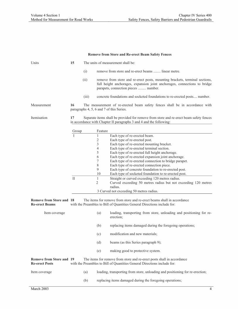
Volume 4 Section 1 Chapter IV Series 400 Method for Measurement for Road Works Safety Fences, Safety Barriers and Pedestrian Guardrails
March 2003 4
Remove from Store and Re-erect Beam Safety Fences
Units 15 The units of measurement shall be: (i) remove from store and re-erect beams ........ linear metre. (ii) remove from store and re-erect posts, mounting brackets, terminal sections,
full height anchorages, expansion joint anchorages, connections to bridge parapets, connection pieces ......... number.
(iii) concrete foundations and socketed foundations to re-erected posts.... number. Measurement 16 The measurement of re-erected beam safety fences shall be in accordance with
paragraphs 4, 5, 6 and 7 of this Series. Itemisation 17 Separate items shall be provided for remove from store and re-erect beam safety fences
in accordance with Chapter II paragraphs 3 and 4 and the following: Group Feature
I 1 Each type of re-erected beam. 2 Each type of re-erected post. 3 Each type of re-erected mounting bracket. 4 Each type of re-erected terminal section. 5 Each type of re-erected full height anchorage. 6 Each type of re-erected expansion joint anchorage. 7 Each type of re-erected connection to bridge parapet. 8 Each type of re-erected connection piece. 9 Each type of concrete foundation to re-erected post. 10 Each type of socketed foundation to re-erected post.
II 1 Straight or curved exceeding 120 metres radius. 2 Curved exceeding 50 metres radius but not exceeding 120 metres
radius. 3 Curved not exceeding 50 metres radius.
Remove from Store and 18 The items for remove from store and re-erect beams shall in accordance Re-erect Beams with the Preambles to Bill of Quantities General Directions include for:
Item coverage (a) loading, transporting from store, unloading and positioning for re-erection;
(b) replacing items damaged during the foregoing operations; (c) modification and new materials; (d) beams (as this Series paragraph 9); (e) making good to protective system. Remove from Store and 19 The items for remove from store and re-erect posts shall in accordance Re-erect Posts with the Preambles to Bill of Quantities General Directions include for: Item coverage (a) loading, transporting from store, unloading and positioning for re-erection; (b) replacing items damaged during the foregoing operations;

Volume 4 Section 1 Chapter IV Series 400 Method for Measurement for Road Works Safety Fences, Safety Barriers and Pedestrian Guardrails
March 2003 5
(c) modification and new materials; (d) posts (as this Series paragraph 10); (e) making good to protective system. Remove from Store and 20 The items for remove from store and re-erect mounting brackets shall in Re-erect Mounting accordance with the Preambles to Bill of Quantities General Directions include Brackets for: Item coverage (a) loading, transporting from store, unloading and positioning for
re-erection; (b) replacing items damaged during the foregoing operations; (c) modification and new materials; (d) mounting brackets (as this Series paragraph 11); (e) making good to protective system. Remove from Store and 21 The items for remove from store and re-erect terminal sections, full Re-erect Terminal height anchorages, expansion joint anchorages, connections to bridge parapets Sections Full Height and connection pieces shall in accordance with the Preambles to Bill of Anchorages Expansion Quantities General Directions include for: Joint Anchorages Connections to Bridge arapets and Connection Pieces Item coverage (a) loading, transporting from store, unloading and positioning for re-erection; (b) replacing items damaged during the foregoing operations;
(c) modification and new materials; (d) terminal sections, full height anchorages, expansion joint anchorages,
connections to bridge parapets and connection pieces (as this Series paragraph 12);
(e) making good to protective system. Concrete Foundations 22 The items for concrete foundations and socketed foundations to and Socketed re-erected posts shall in accordance with the Preambles to Bill of Quantities Foundations to General Directions include for: Re-erected Posts Item coverage (a) concrete foundations to posts (as this Series paragraph 13); (b) socketed foundations to posts (as this Series paragraph 14). Post Extension Units Units 23 The unit of measurement shall be: (i) post extension units .......... number. Itemisation 24 Separate items shall be provided for post extension units in accordance with Chapter II
paragraphs 3 and 4 and the following:

Volume 4 Section 1 Chapter IV Series 400 Method for Measurement for Road Works Safety Fences, Safety Barriers and Pedestrian Guardrails
March 2003 6
Group Feature I 1 Each type of post extension unit.
Post Extension Units 25 The items for post extension units shall in accordance with the Preambles to Bill of
Quantities General Directions include for: Item coverage (a) fabrication (as Series 1800 paragraph 6);
(b) protective system (as Series 1900 paragraph 4); (c) drilling existing posts; (d) fixing to existing posts.
Raising Existing Sockets Units 26 The unit of measurement shall be: (i) raising existing sockets ........... number. Itemisation 27 Separate items shall be provided for raising existing sockets in accordance with
Chapter II paragraphs 3 and 4 and the following:
Group Feature I 1 Raising each type of existing socket.
Raising Existing Sockets 28 The items for raising existing sockets shall in accordance with the Preambles to Bill of
Quantities General Directions include for: Item coverage (a) removing existing posts and setting aside for re-use;
(b) cleaning out sockets; (c) in situ concrete (as Series 1700 paragraph 5); (d) formwork (as Series 1700 paragraph 15); (e) loading, transporting from store, unloading and positioning for re-
erection; (f) removing from store and re-erecting posts (as this Series paragraph
19); (g) replacing items damaged during the foregoing operations; (h) making good to protective systems.
Wire Rope Safety Fence Units 29 The units of measurement shall be: (i) wire rope ........ linear metre.

Volume 4 Section 1 Chapter IV Series 400 Method for Measurement for Road Works Safety Fences, Safety Barriers and Pedestrian Guardrails
March 2003 7
(ii) posts, intermediate anchorages, end anchorages, concrete foundations and socketed foundations to posts ..... number.
Measurement 30 The measurement of wire rope shall be the undeveloped length measured once only
along the centre line of the fence on plan from midway between the anchor blocks at one end to midway between the anchor blocks at the other end.
31 The measurement of intermediate anchorages and end anchorages shall be the complete installation. Concrete foundations and socketed foundations shall only be measured for those locations stated in the Contract.
temisation 32 Separate items shall be provided for wire rope safety fences in accordance with
Chapter II paragraphs 3 and 4 and the following:
Group Feature I 1 Wire rope. 2 Each type of post.
3 Each type of intermediate anchorage. 4 Each type of end anchorage. 5 Each type of concrete foundation to post.
6 Each type of socketed foundation to posts. Wire rope 33 The items for wire rope shall in accordance with the Preambles to Bill of Quantities
General Directions include for: Item coverage (a) fabrication (as Series 1800 paragraph 6); (b) protective system (as Series 1900 paragraph 4); (c) rigging screws, threaded terminals, attachments, fittings and fixings; (d) adjustments and tensioning; (e) threading ropes into and around posts. Posts 34 The items for posts shall in accordance with the Preambles to Bill of Quantities
General Directions include for: Item coverage (a) fabrication (as Series 1800 paragraph 6); (b) protective system (as Series 1900 paragraph 4); (c) driving in any material; (d) fixing to structures including attachment systems; (e) post caps, excluders, hooks and fittings; (f) drilling or forming holes and pockets and casting in bolts, base plates, sockets
and anchorage assemblies; (g) bedding; (h) filling. Intermediate Anchorages 35 The items for intermediate anchorages and end anchorages shall in and End Anchorages accordance with the Preambles to Bill of Quantities General Directions include for:

Volume 4 Section 1 Chapter IV Series 400 Method for Measurement for Road Works Safety Fences, Safety Barriers and Pedestrian Guardrails
March 2003 8
Item coverage (a) fabrication (as Series 1800 paragraph 6); (b) protective system (as Series 1900 paragraph 4); (c) excavation in any material (as Series 600 paragraphs 17, 18, 19 and 23); (d) concrete (as Series 1700 paragraphs 5 and 10); (e) formwork (as Series 1700 paragraph 15); (f) reinforcement (as Series 1700 paragraph 26); (g) disposal of material (as Series 600 paragraph 39); (h) safety check ropes, fork terminals, pins, thimbles, ferrules, attachments,
fixings and fittings; (i) anchor frames, surface mounted anchors and sockets; (j) fixing to anchor block including attachment systems; (k) drilling or forming holes and pockets and casting in bolts, base plates, sockets
and anchorage assemblies. Concrete Foundations 36 The items for concrete foundations to posts shall in accordance To Posts with the Preambles to Bill of Quantities General Directions include for: Item coverage (a) excavation in any material (as Series 600 paragraphs 17, 18, 19 and 23); (b) disposal of material (as Series 600 paragraph 39); (c) concrete (as Series 1700 paragraphs 5 and 10); (d) formwork (as Series 1700 paragraph 15); (e) reinforcement (as Series 1700 paragraph 26); (f) plastic sheeting; (g) casings. Socketed Foundations 37 he items for socketed foundations to posts shall in accordance with the to Posts Preambles to Bill of Quantities General Directions include for: Item coverage (a) fabrication (as Series 1800 paragraph 6); (b) protective system (as Series 1900 paragraph 4); (c) concrete foundations to posts (as this Series paragraph 36); (d) socket covers and filling. Concrete Safety Barriers Units 38 The units of measurement shall be: (i) concrete safety barriers ...... linear metre.
(ii) concrete safety barrier terminations, transitions ...... number. Measurement 39 The measurement of concrete safety barriers shall be the developed length along the
centre line of the barriers between terminations.

Volume 4 Section 1 Chapter IV Series 400 Method for Measurement for Road Works Safety Fences, Safety Barriers and Pedestrian Guardrails
March 2003 9
Itemisation 40 Separate items shall be provided for concrete safety barriers in accordance with
Chapter II paragraphs 3 and 4 and the following:
Group Feature I 1 Each type of barrier.
2 Each type of termination. 3 Each type of transition.
II 1 Straight or curved exceeding 50 metres radius. 2 Curved not exceeding 50 metres radius.
Concrete Safety Barriers 41 The items for concrete safety barriers shall in accordance with the Preambles to Bill of
Quantities General Directions include for: Item coverage (a) excavation in any material (as Series 600 paragraphs 17, 18, 19 and
23); (b) disposal of material (as Series 600 paragraph 39); (c) concrete (as Series 1700 paragraph 5 and 10); (d) formwork (as Series 1700 paragraph 15); (e) reinforcement (as Series 1700 paragraph 26); (f) joints and gaskets including movement joints; (g) foundations and bases; (h) filling; (i) attachment systems and fixings; (j) adjustment to flowing alignment; (k) fabrication (as Series 1800 paragraph 6); (l) protective system (as Series 1900 paragraph 4); (m) cast-in sockets, bolts, nuts, washers; (n) make-up units; (o) dowel bars; (p) treatment at lighting columns and the like including cover plates, sub-frames, plates and fixings.
Concrete Safety Barrier 42 The items for concrete safety barrier terminations and transitions shall in Terminations and accordance with the Preambles to Bill of Quantities General Directions included for: Transitions Item coverage (a) concrete safety barriers (as this Series paragraph 41);
(b) fixing to or setting in concrete; (c) attachment systems and connectors for fixing to beam safety fences.
Pedestrian Guardrails and Handrails

Volume 4 Section 1 Chapter IV Series 400 Method for Measurement for Road Works Safety Fences, Safety Barriers and Pedestrian Guardrails
March 2003 10
Units 43 The unit of measurement shall be: (i) pedestrian guardrails, handrails ........... linear metre. Measurement 44 The measurement of pedestrian guardrails and handrails shall be the developed length
along the centre line. The height of pedestrian guardrails shall be the height between the top of the top rail and the finished level of the surface directly beneath the guardrail.
Itemisation 45 Separate items shall be provided for pedestrian guardrails and handrails in accordance
with Chapter II paragraphs 3 and 4 and the following:
Group Feature I 1 Each type of pedestrian guardrail.
2 Each type of handrail. II 1 Different heights.
III 1 Elements curved in plan to different radii. Pedestrian Guardrails 46 The items for pedestrian guardrails and handrails shall in and Handrails accordance with the Preambles to Bill of Quantities General Directions include for: Item coverage (a) excavation in any material (as Series 600 paragraphs 17, 18, 19 and 23);
(b) disposal of material (as Series 600 paragraph 39); (c) in situ concrete (as Series 1700 paragraph 5); (d) formwork (as Series 1700 paragraph 15); (e) reinforcement (as Series 1700 paragraph 26); (f) backfilling and compaction; (g) metal parapets (as Series 2200 paragraph 5); (h) gates (as Series 300 paragraph 6); (j) rivets, nuts, bolts, shims, washers, welds, clamps and the like.
Loading Tests on Post Foundations Units 47 The unit of measurement for loading test on post foundation shall be:
(i) loading test on post foundation carried out by Contractor, loading test on post foundation carried out by Overseeing Organisation ………… number.
Itemisation 48 Separate items shall be provided for loading test on post foundation in accordance with
Chapter II paragraphs 3 and 4 and the following:
Group Feature I 1 Loading test on post foundation carried out by Contractor.
2 Loading test on post foundation carried out by Overseeing Organisation.
II 1 Different types of safety fence posts. III 1 Different sizes of safety fence posts.
Loading Test on Post 49 The items for loading test on post foundation carried out by Foundation Carried Contractor shall in accordance with the Preambles to Bill of Quantities Out by Contractor General Directions include for:

Volume 4 Section 1 Chapter IV Series 400 Method for Measurement for Road Works Safety Fences, Safety Barriers and Pedestrian Guardrails
March 2003 11
Item coverage (a) posts (as this Series paragraph 10); (b) concrete foundations to posts (as this Series paragraph 13); (c) socketed foundations to posts (as this Series paragraph 14); (d) provision, maintenance and subsequent removal of test equipment; (e) provision, maintenance and subsequent removal of reaction vehicle; (f) preparation and submission of results to the Overseeing Organisation; (g) removal of test posts and foundations; (h) disposal of material (as Series 600 paragraph 39); (i) reinstatement and making good; (j) traffic safety and management (as Series 100 paragraph 26). Loading Test on Post 50 The items for loading test on post foundation carried out by Foundation Carried Overseeing Organisation shall in accordance with the Preambles to Bill of Out by Overseeing Quantities General Directions include for: Organisation Item coverage (a) posts (as this Series paragraph 10); (b) concrete foundations to posts (as this Series paragraph 13); (c) socketed foundations to posts (as this Series paragraph 14); (d) provision, maintenance and subsequent removal of reaction vehicle; (e) removal of test posts and foundations; (f) disposal of material (as Series 600 paragraph 39); (g) reinstatement and making good; (h) traffic safety and management (as Series 100 paragraph 26).

Volume 4 Section 2 Chapter IV Series 300 Notes for Guidance on the Method of Measurement for Road Works Fencing
March 2003 1
Series 300: Fencing
Volume 4 home page
1 Temporary Fencing The Specification requires the Contractor to erect temporary fencing in all situations where he does not provide permanent fencing immediately. To comply with the Specification, Health and Safety Regulations and the Conditions of Contract the Contractor has the choice of a range of four specified types of temporary fencing. This temporary fencing is not shown on the Drawings nor is it included in the Bill of Quantities. However, should some specific temporary fencing be required by the Overseeing Organisation then this should be shown on the Drawings and included within Appendix 3/1 and the Bill of Quantities. The Compiler should ensure that the obligations under the Form of Contract being utilised are sufficient and adequately cover the particular requirements of an individual scheme. 2 Concrete Foundations or Longer Posts Items are provided in the MMRW for concrete foundations to timber posts. These are only to be measured where such a requirement is identified in Appendices 1/15 or 3/1 of the Specification. Foundations in all other circumstances, including those for all posts other than timber, shall be deemed to be included within the fencing item to which they relate. Locations where longer posts are required should also be identified in Appendices 1/15 or 3/1, a specific Type reference should be given, and reference made in item descriptions.
Volume 4 home page

Volume 4 Chapter IV Series 500 Method of Measurement for Road Works Drainage and Service Ducts
March 2003 1
Series 500: Drainage and Service Ducts
Definitions 1 Any reference to ‘drain’ shall be deemed to include sewers and piped culverts.
2 Drains exceeding 900 mm internal diameter, box culverts, piped culverts and all associated chambers, headwalls, outfall works and concrete bagwork shall be measured in accordance with Series 2500 Special Structures.
3 Trenches and ducts in connection with electrical work for road lighting and traffic
signs cabling shall be measured in accordance with Series 1400.
4 Trenches and ducts in connection with motorway communications cabling shall be measured in accordance with Series 1500.
5 The Earthworks Outline is defined in Series 600 Earthworks paragraphs 1 to 6
inclusive and shall apply equally to this Series. 6 Where the ground level has been subjected to treatment, under the Contract, in respect
of ground improvement, mine workings, swallow holes and the like, for the purposes of this Series Existing Ground Level shall be the level obtained upon completion of any such treatment of the areas affected.
7 Sub-soil Level is defined as the level of the ground after the removal of topsoil required by the Contract.
8 Surcharge is defined as material placed on embankments for the purpose of loading the embankment for the periods stated in the Contract.
Drains and Service Ducts (Excluding Filter Drains, Narrow Filter Drains and Fin Drains)
Unit 9 The unit of measurement for drains and service ducts shall be:
(i) drains, service ducts ............ linear metre.
Measurement 10 The measurement of drains and service ducts shall be the summation of their individual lengths measured along the centre lines of the pipes between any of the following: (a) the internal faces of chambers; (b) the external faces of headwalls; (c) the intersections of the centre lines at pipe junctions; (d) the centre of gully gratings (or where no grating is provided, the centre of the gully); (e) the position of terminations shown in the Contract; (f) the point of change of stage depth.
11 The depth of drains and service ducts shall be the vertical measurement between the invert and the following:
(a) where the invert is below the Existing Ground Level - the Existing Ground Level except that where the Earthworks Outline is below the Existing Ground Level the measurement shall be taken to the Earthworks Outline;
(b) where the invert is at or above the Existing Ground Level - the

Volume 4 Chapter IV Series 500 Method of Measurement for Road Works Drainage and Service Ducts
March 2003 2
datum stated in the Contract, or where none is stated, the Earthworks Outline.
Notwithstanding the foregoing, where in the Contract a commencing level or a minimum level of cover is stated from which excavation shall commence, then the depth shall be taken to that stated level.
12 The average depth to invert shall be the calculated arithmetic mean
of the depths taken at intervals of 10 metres along the pipelines starting from the outfall end. For terminal lengths and pipelines less than 10 metres long the measurement of depths shall be taken at their ends.
13 The measurement of service ducts shall be for the complete construction irrespective of the number of ducts contained within any one trench. Where more than one duct is laid in a trench then the number of ducts shall be stated in the item description.
14 Drains and service ducts required to be designed by the Contractor shall be measured in accordance with Series 2500.
Itemisation 15 Separate items shall be provided for drains and service ducts (excluding filter drains, narrow filter drains and fin drains) in accordance with Chapter II paragraphs 3 and 4 and the following:
Group Feature I 1 Drains.
2 Service ducts.
II 1 Different internal diameters. III 1 Depths to invert not exceeding 2 metres. The average depth to invert to be stated to the nearest 25 mm.
2 Depths to invert exceeding 2 metres but not exceeding 4 metres and so on in steps of 2 metres.
The average depth to invert to be stated to the nearest 25 mm.
IV 1 Specified design groups.
2 Particular designs stated in the Contract V 1 Construction in trench.
2 Construction in heading. 3 Construction by jacking or thrust boring. 4 Suspended on discrete supports.
VI 1 In side slopes of cuttings or side slopes of embankments. Note: For each item which includes Group III Feature 1 or 2, an associated item shall be provided for adjustment of the rate for each 25 mm of difference in excess of 150 mm where the average depth to invert calculated from site measurement varies from that stated in the Bill of Quantities. The foregoing shall apply to both increases and decreases of average in excess of 150 mm, and will result in

Volume 4 Chapter IV Series 500 Method of Measurement for Road Works Drainage and Service Ducts
March 2003 3
either a positive or negative adjustment of the rate. Drains and Service Ducts
16 The items for drains and service ducts shall in accordance with the Preambles to Bill of Quantities General Directions include for: Item coverage (a) excavation of acceptable material (as Series 600 paragraphs 17 and 18); (b) excavation of unacceptable material (as Series 600 paragraph 19); (c) access shafts to headings and their subsequent reinstatement; (d) thrust pits and thrust blocks for pipe jacking and their removal on completion; (e) articulated pipes and fittings;
(f) cutting, laying, jointing and bedding; (g) building in pipes to headwalls and outfall works; (h) hangers, stools and discrete supports;
(i) bedding, haunching and surrounding;
(j) formwork (as Series 1700 paragraph 15); (k) backfilling and compaction;
(l) disposal of material (as Series 600 paragraph 39);
(m) movement joints to beds, surrounds and the like;
(n) reinstatement of unpaved areas;
(o) checking and cleaning;
(p) recording, staking and labelling;
(q) in the case of ducts, fixing draw ropes, removable stoppers, marker blocks and posts; (r) pipe schedules;
(s) lubricants, packing, grouting and caulking;
(t) surveys and recordings;
(u) protective system (as Series 1900 paragraph 4).
Filter Drains
Units 17 The units of measurement for filter drains shall be:
(i) filter drains ......... linear metre. (ii) filter material contiguous with filter drains ......... cubic metre. (iii) sub-base material ......... cubic metre.

Volume 4 Chapter IV Series 500 Method of Measurement for Road Works Drainage and Service Ducts
March 2003 4
(iv) lightweight aggregate infill .......... cubic metre.
(v) excavate and replace filter material ……. cubic metre. Measurement 18 The measurement of filter drains, excluding narrow filter drains,
shall be the summation of their individual lengths measured along the center lines of the pipe (or trench where no pipe is provided), between any of the following: (a) the internal faces of chambers; (b) the external faces of headwalls;
(c) the intersection of centre lines at junctions;
(d) the centre of gully gratings (or where no grating is provided the centre of the gully);
(e) the position of terminations shown in the Contract;
(f) the point of change of stage depth.
19 The depth of filter drains shall be the vertical measurement between the invert (or the centre line of the trench bottom where no pipe is provided) and the following: (a) where the invert is below the Existing Ground Level - the Existing Ground Level or the Earthworks Outline whichever is the lower, except that where the finished level of the filter material is above the Existing Ground Level the measurement shall be taken to the finished level of the filter material; (b) where the invert is at or above the Existing Ground Level - the datum stated in the Contract, or where none is stated, the finished level of the filter material. The calculation of average depth to invert of filter drains shall be as paragraph 12 of this Series taken along the centre line of the filter drain. Narrow filter drains shall be measured in accordance with paragraphs 25 to 28 of this Series.
20 The measurement of contiguous filter material shall be the volume of the material occupying the void between the filter drain and the adjacent carriageway, hardshoulder and hardstrip. The side of the contiguous filter material next to the filter drain shall be taken as the vertical extension of the trench side above capping or where no capping is provided above subgrade level. The measurement of sub-base material shall be the volume of the sub-base material within non-pavement verge or central reserve adjacent to the carriageway, hardshoulder and hardstrip filled to the outline stated in the Contract. The measurement of lightweight aggregate infill shall be the volume of the lightweight aggregate infill above the filter drain filled to the outline stated in the Contract. The measurement of excavate and replace filter material shall be the product of the lengths, widths and depths instructed by the Overseeing Organisation with no deduction for pipes, ducts or chambers. Lengths and widths shall be taken asthe lengths and widths at the level of the drain invert or, in the case that partial excavation is instructed, at the depth to which excavation is instructed by the Overseeing Organisation.
Itemisation 21 Separate items shall be provided for filter drains in accordance with Chapter II paragraphs 3 and 4 and the following:

Volume 4 Chapter IV Series 500 Method of Measurement for Road Works Drainage and Service Ducts
March 2003 5
Group Feature I 1 Filter drains.
2 Filter material contiguous with filter drains. 3 Sub-base material. 4 Lightweight aggregate infill. 5 Excavate and replace filter material.
II 1 Different internal diameters.
2 Different types of filter material. 3 Different types of sub-base material. 4 Different types of lightweight aggregate infill.
III 1 Depths to invert not exceeding 2 metres. The average depth to invert to be stated to the nearest 25 mm.
2 Depths to invert exceeding 2 metres but not exceeding 4 metres and so on in steps of 2 metres. The average depth to invert to be stated to the nearest 25 mm.
IV 1 Specified design groups.
2 Particular designs stated in the Contract.
V 1 In side slopes of cuttings or side slopes of
embankments.
Note: For each item which includes Group III Feature 1 or 2 an associated item shall be provided for adjustment of the rate for each 25 mm of difference in excess of 150 mm where the average depth to invert calculated from site measurement varies from that stated in the Bill of Quantities. The foregoing shall apply to both increases and decreases of average in excess of 150 mm, and will result in either a positive or negative adjustment of the rate.
Filter Drains 22 The items for filter drains shall in accordance with the Preambles to Bill of Quantities General Directions include for:
Item coverage (a) excavation of acceptable material (as Series 600 paragraphs 17 and 18);
(b) excavation of unacceptable material (as Series 600 paragraph 19);
(c) disposal of material (as Series 600 paragraph 39); (d) articulated pipes, and fittings;
(e) cutting, laying, jointing and bedding;
(f) bedding, haunching and surrounding;
(g) formwork (as Series 1700 paragraph 15);
(h) filter material and compaction;
(i) reinstatement of unpaved areas;

Volume 4 Chapter IV Series 500 Method of Measurement for Road Works Drainage and Service Ducts
March 2003 6
(j) checking and cleaning;
(k) recording, staking and labelling;
(l) geotextiles;
(m) topsoiling, seeding and turfing;
(n) mesh;
(o) pipe schedules;
(p) protective system (as Series 1900 paragraph 4).
Filter Material Contiguous 23 The items for filter material contiguous with filter drains, with Filter Drains, Sub-base sub-base material and lightweight aggregate infill shall in Material and Lightweight accordance with the Preambles to Bill of Quantities General Aggregate Infill Directions include for: Item coverage (a) compaction;
(b) formwork (as Series 1700 paragraph 15);
(c) geotextiles;
(d) mesh.
Excavate and Replace Filter 24 The items for excavate and replace filter material shall in Material accordance with the Preambles to Bill of Quantities General Directions
include for: Item coverage (a) excavation (as Series 600 paragraphs 18 and 19);
(b) disposal of material (as Series 600 paragraph 39);
(c) compaction of fill (as Series 600 paragraph 52);
(d) geotextiles.
Fin Drains and Narrow Filter Drains
Units 25 The unit of measurement shall be: (i) fin drains ............ linear metre.
(ii) narrow filter drains .......... linear metre.
Measurement 26 The measurement of fin drains and narrow filter drains shall
be the summation of their individual lengths measured along their centre lines between any of the following: (a) the internal faces of chambers; (b) the position of terminations shown in the Contract;

Volume 4 Chapter IV Series 500 Method of Measurement for Road Works Drainage and Service Ducts
March 2003 7
(c) the external faces of headwalls.
The depth of the fin drain or narrow filter drain shall be the vertical measurement between the invert and the Earthworks Outline.
Itemisation 27 Separate items shall be provided for fin drains and narrow filter drains in accordance with Chapter II paragraphs 3 and 4 and the following:
Group Feature I 1 Fin drains.
2 Narrow filter drains.
II 1 Specified design group. 2 Particular designs stated in the Contract.
III 1 Depth not exceeding 1.5 metres.
Fin Drains and Narrow Filter Drains 28 The items for fin drains and narrow filter drains shall in
accordance with the Preambles to Bill of Quantities General Directions include for: Item coverage (a) geotextiles and cores;
(b) backfilling and compaction;
(c) filter drains (as this Series paragraph 22);
(d) protection from ultra-violet light;
(e) marker tapes;
(f) lapping and jointing; (g) connections, attachments and fittings;
(h) treatment at chambers, gullies, pipelines and the like.
Connections
Units 29 The unit of measurement for connections shall be:
(i) connection to existing drain, existing piped culvert, existing chamber, permanently severed land or mole drain ............... number.
Measurement 30 Connections shall only be separately measured for connection to existing drains, existing piped culverts or existing chambers, and permanently severed land or mole drains.
Itemisation 31 Separate items shall be provided for connections in accordance with Chapter II paragraphs 3 and 4 and the following:

Volume 4 Chapter IV Series 500 Method of Measurement for Road Works Drainage and Service Ducts
March 2003 8
Group Feature I 1 Connection to existing drain and existing piped culvert.
2 Connection to existing chamber. 3 Connection to permanently severed land or mole drain.
II 1 Different diameters. III 1 Depths to invert not exceeding 2 metres.
2 Depths to invert exceeding 2 metres but not exceeding 4 metres and so on in steps of 2 metres.
Connections to Existing 32 The items for connection to existing drains, existing piped Drains, Existing Piped culverts, existing chambers, permanently severed land or mole drains Culverts, Existing shall in accordance with the Preambles to Bill of Quantities General Chambers, Permanently for: Severed Land or Mole Drains Item coverage (a) excavation of acceptable material (as Series 600 paragraphs 17 and
18);
(b) excavation of unacceptable material (as Series 600 paragraph 19);
(c) locating and making entry;
(d) backfilling and compaction;
(e) disposal of material (as Series 600 paragraph 39);
(f) making entry into chambers, concrete benching and channels, and making good the benching, channels and walls;
(g) locating severed ends of land and mole drains;
(h) pipes, fittings and saddles;
(i) bedding, haunching and surrounding, and filter material;
(j) formwork (as Series 1700 paragraph 15);
(k) sealing off disused ends;
(l) re-laying existing pipes disturbed.
Chambers and Gullies
Units 33 The unit of measurement shall be:
(i) chambers, gullies ............ number.
Measurement 34 The measurement shall be of the complete chamber or gully.
35 Depths of chambers shall be the distance between the top surface of the cover and the invert of the main channel, or where no channel is required by the Contract, the uppermost surface of the base slab.
Where no base slab is required the depth shall be taken to the bottom of the excavation.

Volume 4 Chapter IV Series 500 Method of Measurement for Road Works Drainage and Service Ducts
March 2003 9
Itemisation 36 Separate items shall be provided for chambers and gullies in
accordance with Chapter II paragraphs 3 and 4 and the following: Group Feature I 1 Chambers.
2 Gullies.
II 1 Specified design groups.
2 Particular designs stated in the Contract.
III 1 Depths not exceeding 1 metre.
2 Depths exceeding 1 metre but not exceeding 2 metres 3 and so on in steps of 1 metre
IV 1 Different types of covers or gratings.
Chambers 37 The items for chambers shall in accordance with the Preambles to Bill of Quantities General Directions include for:
Item coverage (a) excavation of acceptable material (as Series 600 paragraphs 17 and 18);
(b) excavation of unacceptable material (as Series 600 paragraph 19);
(c) locating existing drains;
(d) breaking into existing drains;
(e) connecting and re-connecting existing drains;
(f) construction of bases, walls, roof and cover slabs and shafts, surrounds and corbelling for cover;
(g) channels, fittings, benchings, building in pipes and fin drain
connections;
(h) cleaning;
(i) steps, safety chains, ladders, handholds and the like;
(j) covers, frames, seatings and bedding;
(k) lifting keys;
(l) concrete (as Series 1700 paragraphs 5 and 10);
(m) formwork (as Series 1700 paragraph 15);
(n) reinforcement (as Series 1700 paragraph 26);
(o) backfilling and compaction;
(p) disposal of material (as Series 600 paragraph 39);

Volume 4 Chapter IV Series 500 Method of Measurement for Road Works Drainage and Service Ducts
March 2003 10
(q) filling;
(r) notices;
(s) sealants (as Series 2300 paragraph 10); (t) brickwork (as Series 2400 paragraph 4);
(u) re-laying existing pipes disturbed; (v) pipework and fittings; (w) penstocks and ancillary equipment.
Gullies 38 The items for gullies shall in accordance with the Preambles to Bill of Quantities General Directions include for:
Item coverage (a) excavation of acceptable material (as Series 600 paragraphs 17 and 18);
(b) excavation of unacceptable material (as Series 600 paragraph 19);
(c) fittings including in situ concrete (as Series 1700 paragraph 5) bed and surround and jointing to pipes;
(d) gratings, frames, slabs, surrounds, aprons, seatings, liners and bedding;
(e) formwork (as Series 1700 paragraph 15);
(f) cleaning;
(g) backfilling and compaction;
(h) disposal of material (as Series 600 paragraph 39); (i) brickwork (as Series 2400 paragraph 4); (j) re-laying existing pipes disturbed.
Headwalls and Outfall Works
Measurement 39 Headwalls and outfall works and the like to pipes up to 900 mm internal diameter shall be measured in accordance with this Series paragraphs 40 to 42. Headwalls and outfall works and the like to pipes exceeding 900 mm internal diameter shall be measured in accordance with Series 2500. Headwalls and outfall works and the like constructed using concrete bagwork shall be measured in accordance with this Series paragraphs 77 to 80.
Units 40 The unit of measurement shall be:
(i) headwalls, revetments ........ number.
Itemisation 41 Separate items shall be provided for headwalls and revetments in accordance with Chapter II paragraphs 3 and 4 and the following:
Group Feature

Volume 4 Chapter IV Series 500 Method of Measurement for Road Works Drainage and Service Ducts
March 2003 11
I 1 Headwalls.
2 Revetments II 1 Different types. III 1 Different materials IV 1 Pipe not exceeding 100 mm internal diameter.
2 Pipe exceeding 100 mm but not exceeding 300 mm internal diameter. 3 Pipe exceeding 300 mm but not exceeding 600 mm internal diameter. 4 Pipe exceeding 600 mm but not exceeding 900 mm internal
diameter.
Headwalls and 42 The items for headwalls and outfall works shall in accordance with Outfall Works the Preambles to Bill of Quantities General Directions include for: Item coverage (a) excavation of acceptable material (as Series 600 paragraphs 17 and
18); (b) excavation of unacceptable material (as Series 600 paragraph 19);
(c) concrete (as Series 1700 paragraphs 5 and 10);
(d) formwork (as Series 1700 paragraph 15);
(e) backfilling and compaction;
(f) disposal of material (as Series 600 paragraph 39);
(g) brickwork, copings, string courses and the like (as Series 2400
paragraph 4);
(h) blockwork, stonework, copings, string courses, individual blocks, features or stones (as Series 2400 paragraph 8);
(i) lining of watercourses (as Series 600 paragraph 89); (j) drainage channel blocks (as Series 1100 paragraph 4); (k) building in pipes and fin drain connections;
(l) reinforcement (as Series 1700 paragraph 26); (m) miscellaneous metalwork (as Series 1800 paragraph 14); (n) waterproofing (as Series 2000 paragraph 4); (o) flap valves. Soft Spots and Other Voids
Units 43 The unit of measurement shall be:
(i) soft spots, other voids ......... cubic metre.
Measurement 44 The measurement of soft spots and other voids shall be the volume

Volume 4 Chapter IV Series 500 Method of Measurement for Road Works Drainage and Service Ducts
March 2003 12
of the void directed to be excavated or filled. For this measurement the width shall be taken for drains, service ducts and filter drains, as the internal diameter of the pipe plus 600 mm. Where no pipe is required the width shall be taken as 600 mm. For chambers, gullies and the like the measurement shall be taken as the horizontal area of the base slab or where no base slab is required the bottom of the excavation. The depths shall be measured from the underside of the thinnest permitted bed in any one group for trenches and from the underside of the base slab for chambers, gullies and the like.
Itemisation 45 Separate items shall be provided for soft spots and other voids in
accordance with Chapter II paragraphs 3 and 4 and the following:
Group Feature I 1 Excavation of soft spots and other voids.
2 Filling of soft spots and other voids. II 1 Different types of fill.
Excavation of Soft Spots and other Voids 46 The items for excavation of soft spots and other voids shall in
accordance with the Preambles to Bill of Quantities General Directions include for:
Item coverage (a) excavation of acceptable material (as Series 600 paragraphs 17 and 18); (b) excavation of unacceptable material (as Series 600 paragraph 19);
(c) disposal of material (as Series 600 paragraph 39).
Filling of Soft Spots 47 The items for filling of soft spots and other voids shall in and Other Voids accordance with the Preambles to Bill of Quantities General Directions include for: Item coverage (a) deposition of fill (as Series 600 paragraph 33);
(b) compaction of fill (as Series 600 paragraph 52);
(c) in situ concrete (as Series 1700 paragraph 5);
(d) formwork (as Series 1700 paragraph 15).
Supports Left in Excavation
Units 48 The unit of measurement shall be:
(i) supports left in excavation .......... square metre.
Measurement 49 The measurement shall be the area of face required by the Contract to be left with supports in position .
Itemisation 50 Separate items shall be provided for supports left in excavation in accordance with Chapter II paragraphs 3 and 4 and the following:
Group Feature I 1 Supports.

Volume 4 Chapter IV Series 500 Method of Measurement for Road Works Drainage and Service Ducts
March 2003 13
II 1 Timber. 2 Steel III 1 Different types. IV 1 Construction in trench.
2 Construction in pits. 3 Construction in heading.
Supports Left in Excavation 51 The items for supports left in excavation shall in accordance with
the Preambles to Bill of Quantities General Directions include for:
Item coverage (a) struts, walings and the like and working around them. Drainage and Service Ducts in Structures (Including Reinforced Earth Structures and Anchored Earth Structures)
Units 52 The unit of measurement shall be:
(i) drainage and service ducts in structures ............ item. Measurement 53 The components comprising the items of drainage and service
ducts in structures shall be identified and scheduled in the Contract.
Itemisation 54 Separate items shall be provided for drainage and service ducts in structures in accordance with Chapter II paragraphs 3 and 4 and the following:
Group Feature I 1 Drainage.
2 Service ducts II 1 Substructure - end supports.
2 Substructure - intermediate supports. 3 Superstructure. 4 Reinforced earth structure. 5 Anchored earth structure.
Drainage and Service 55 The items for drainage and service ducts in structures shall in Ducts in Structures accordance with the Preambles to Bill of Quantities General Directions include for: Item coverage (a) drains, service ducts, filter drains, fin drains and narrow filter
drains and connections (as this Series paragraphs 16,22, 28 and 32);
(b) chambers (as this Series paragraph 37);
(c) gullies (as this Series paragraph 38);
(d) pipework, gullies, downpipes, fittings and the like including brackets, hangers and straps, fixing to or building into the structure; (e) making good protective system, waterproofing;
(f) permeable backing including compaction and supports;

Volume 4 Chapter IV Series 500 Method of Measurement for Road Works Drainage and Service Ducts
March 2003 14
(g) channels.
Filling to Pipe Bays and Verges on Bridges
Units 56 The unit of measurement shall be:
(i) filling to pipe bays and verges on bridges .......... cubic metre.
Measurement 57 The measurement shall be the volume of the void stated in the Contract to be filled except that no deduction shall be made for drains, service ducts, services, supplies and the like and their supports.
Itemisation 58 Separate items shall be provided for filling to pipe bays and verges on bridges in accordance with Chapter II paragraphs 3 and 4 and the following:
Group Feature I 1 Filling to pipe bays and verges on bridges. II 1 Different types.
Filling to Pipe Bays 59 The items for filling to pipe bays and verges on bridges shall in and Verges on Bridges accordance with the Preambles to Bill of Quantities General Directions include for: Item coverage (a) deposition;
(b) complying with any restrictions on the placing and compacting of materials;
(c) compaction around drains, service ducts, services, supplies, supports and the like.
Replacement, Raising or Lowering of Covers and Gratings on Existing Chambers and Gullies
Definition 60 For the purpose of paragraphs 61 to 64 of this Series any reference to covers and gratings shall be deemed to include associated frames.
Units 61 The units of measurement shall be:
(i) replacement of covers and gratings on existing chambers and gullies ……… number.
(ii) raising or lowering of covers and gratings on existing chambers and gullies …….. number.
Measurement 62 When an existing cover or grating is to be raised/lowered and
replaced, separate items shall be measured for raising/lowering and replacement.
Itemisation 63 Separate items shall be provided for replacement, raising or
lowering of covers and gratings on existing chambers and gullies in accordance with Chapter II paragraphs 3 and 4 and the following:

Volume 4 Chapter IV Series 500 Method of Measurement for Road Works Drainage and Service Ducts
March 2003 15
Group Feature I 1 Replacement.
2 Raising the level. 3 Lowering the level.
II 1 Different sizes of cover.
2 Different sizes of grating. III 1 Different types of cover.
2 Different types of grating. IV 1 Different sizes of chamber.
2 Different sizes of gully. V 1 Different construction of chamber.
2 Different construction of gully. VI 1 Not exceeding 150 mm.
2 Exceeding 150 mm but not exceeding 300 mm and so on in steps of 150 mm.
Replacement, Raising 64 The items for replacement, raising or lowering of covers and or Lowering of Covers gratings on existing chambers and gullies shall in accordance with and gratings on Existing the Preambles to Bill of Quantities General Directions include for: Chambers and Gullies Item coverage (a) excavation of acceptable material (as Series 600 paragraphs 17 and
18);
(b) excavation of unacceptable material (as Series 600 paragraph 19);
(c) excavation of Hard Material (as Series 600 paragraph 23);
(d) take up existing cover or grating including frame and clean and set aside for re-use;
(e) demolition and preparation to receive new construction;
(f) construction of walls, roof and cover slabs and shafts, surrounds and corbelling for cover and making good;
(g) steps, safety chains, ladders, handholds, lifting keys and the like;
(h) bedding cover or grating including frame;
(i) concrete (as Series 1700 paragraphs 5 and 10);
(j) formwork (as Series 1700 paragraph 15);
(k) reinforcement (as Series 1700 paragraph 26);

Volume 4 Chapter IV Series 500 Method of Measurement for Road Works Drainage and Service Ducts
March 2003 16
(l) backfilling and compaction;
(m) disposal of material (as Series 600 paragraph 39);
(n) taking precautions to avoid damage to drains;
(o) cleaning;
(p) reinstatement of adjacent surfaces;
(q) brickwork (as Series 2400 paragraph 4);
(r) sealants (as Series 2300 paragraph 10);
(s) modification and new materials;
(t) replacing items damaged during the foregoing operations. Remove from Store and Reinstall Chamber Covers and Frames, and Gully Gratings and Frames
Units 65 The unit of measurement shall be:
(i) remove from store and reinstall chamber covers and frames, and gully gratings and frames .......... number.
Measurement 66 The measurement of remove from store and reinstall chamber
covers and frames and gully gratings and frames shall be the complete installation.
Itemisation 67 Separate items shall be provided for remove from store and reinstall chamber covers and frames and gully gratings and frames in accordance with Chapter II paragraphs 3 and 4 and the following:
Group Feature I 1 Remove from store and reinstall different types of chamber covers and frames.
2 Remove from store and reinstall different types of Gully gratings and frames.
II 1 Different sizes.
Remove from Store 68 The items for remove from store and reinstall chamber covers and Reinstall Chamber and frames and gully gratings and frames shall in accordance with t and Frames and Gully the Preambles to Bill of Quantities General Directions include for: Gratings and Frames Item coverage (a) loading, transporting from store, unloading and positioning for
reinstallation;
(b) replacing items damaged during the foregoing operations;
(c) modification and new materials;
(d) replacement, raising or lowering of covers and gratings on existing chambers and gullies (as this Series paragraph 64).
Grouting Up of Existing Drains and Service Ducts

Volume 4 Chapter IV Series 500 Method of Measurement for Road Works Drainage and Service Ducts
March 2003 17
Units 69 The unit of measurement shall be:
(i) grouting up of existing drains and service ducts ......... linear metre. Measurement 70 The measurement of grouting up of existing drains and service
ducts shall be the length to be grouted as stated in the Contract. Itemisation 71 Separate items shall be provided for grouting up of existing drains
and service ducts in accordance with Chapter II paragraphs 3 and 4 and the following: Group Feature I 1 Grouting up of existing drains and service
ducts.
II 1 Different diameters. III 1 Different types of grout.
Grouting Up of Existing Drains and Service 72 The items for grouting up of existing drains and service ducts shall Ducts in accordance with the Preambles to Bill of Quantities General Directions include for: Item coverage (a) excavation of acceptable material (as Series 600 paragraphs 17 and
18);
(b) excavation of unacceptable material (as Series 600 paragraph 19);
(c) breaking into drain or service duct and cleaning;
(d) mixing and placing grout;
(e) in situ concrete (as Series 1700 paragraph 5);
(f) formwork (as Series 1700 paragraph 15);
(g) backfilling and compaction;
(h) disposal of material (as Series 600 paragraph 39). Excavation in Hard Material
Units 73 The unit of measurement shall be:
(i) extra over excavation for excavation in Hard Material in drainage ......... cubic metre.
Measurement 74 The measurement shall be the volume of the voids formed by the removal of the Hard Material.
For the measurement of:
(a) drains, service ducts and filter drains (except fin drains and narrow filter drains), the width shall be taken as the internal diameter of the pipe plus 600 mm. Where no

Volume 4 Chapter IV Series 500 Method of Measurement for Road Works Drainage and Service Ducts
March 2003 18
pipe is required the width shall be taken as 600 mm;
(b) fin drains and narrow filter drains the width shall be taken as 300mm
(c) chambers, gullies and the like the area shall be taken as the horizontal area of the base slab or where no base slab is required the area of the bottom of the excavation;
(d) Excavation in hard material shall not be measured separately in connection with replacement and raising or lowering of covers and gratings on existing chambers and gullies.
Itemisation 75 Separate items shall be provided for extra over excavation for
excavation in Hard Material in drainage in accordance with Chapter II paragraphs 3 and 4 and the following:
Group Feature I 1 Extra over excavation for excavation in Hard
Material in drainage.
Extra Over Excavation for 76 The items for extra over excavation for excavation in Hard Excavation in Hard Material Material in drainage shall in accordance with the Preambles to Bill of
Quantities General Directions include for: Item coverage (a) excavation in Hard Material (as Series 600 paragraph 23).
Concrete Bagwork Units 77 The unit of measurement shall be:
(i) Concrete bagwork ……………..cubic metre. Measurement 78 No deduction shall be made for holes, ducts, pockets, sockets,
mortices and the like not exceeding 0.15 cubic metres each in volume.
Itemisation 79 Separate items shall be provided for concrete bagwork in accordance with Chapter II paragraphs 3 and 4 and the following:
Group Feature I 1 Concrete bagwork. II 1 In headwalls.
2 Other stated location.
III 1 With battered face.
Concrete Bagwork 80 The items for concrete bagwork shall in accordance with the Preambles to Bill of Quantities General Directions include for:

Volume 4 Chapter IV Series 500 Method of Measurement for Road Works Drainage and Service Ducts
March 2003 19
Item Coverage (a) excavation (as Series 600 paragraphs 18 and 19);
(b) disposal of material (as Series 600 paragraph 39);
(c) trials and trial panels;
(d)deposition, fill and compaction (as Series 600 paragraphs 33, 45 and 52); (e) filling bags with concrete and tucking in ends of bags;
(f) shaping bags and soaking;
(g) dowel bars (as Series 1700 paragraph 27);
(h) building in pipes;
(i) tying into existing work;
(j) construction of bagwork in more than one lift;
(k) in situ concrete (as Series 1700 paragraph 5);
(l) formwork (as Series 1700 paragraph 15);
(m) reinforcement (as Series 1700 paragraph 26);
(n) geotextiles (as Series 600 paragraph 60);
(o) water supply.
Cleaning Existing Drainage Systems Units 81 The units of measurement shall be:
(i) cleaning of piped drainage systems, drainage channels, linear drainage channel systems, combined drainage and kerb systems…………………….linear metre.
(ii) cleaning of bridge drainage system …………item.
(iii) cleaning of chambers, gullies ……………….number.
Measurement 82 The measurement of cleaning piped drainage systems, drainage channels,
linear drainage channel systems and combined drainage and kerb systems shall be the individual lengths measured along the centre lines between any of the following:
(a) the internal faces of chambers;
(b) the external faces of headwalls;
(c) the intersections of the centre lines at pipe junctions;
(d) the centre of gully gratings (or where no grating is provided, the centre of the gully);
(e) the position of terminations shown in the Contract.
The measurement of cleaning drainage channels, linear drainage channel systems, combined drainage and kerb systems and bridge drainage systems shall be deemed to include associated chambers, sumps and the like.

Volume 4 Chapter IV Series 500 Method of Measurement for Road Works Drainage and Service Ducts
March 2003 20
Itemisation 83 Separate items shall be provided for cleaning existing drainage
systems in accordance with Chapter II paragraphs 3 and 4 and the following: Group Feature I 1 Cleaning.
II 1 Piped drainage system.
2 Drainage channels. 3 Linear drainage channel system. 4 Combined drainage and kerb system. 5 Bridge drainage system. 6 Chambers. 7 Gullies.
III 1 Different stated sizes.
IV 1 Different stated locations.
Cleaning Existing Drainage Systems 84 The items for cleaning existing drainage systems shall in
accordance with the Preambles to Bill of Quantities General Directions include for: Item Coverage (a) marking;
(b) lifting chamber covers, replacement and bedding;
(c) rodding;
(d) flushing;
(e) water supply; (f) mandrelling;
(g) disposal of material (as Series 600 paragraph 39);
(h) recording and reporting;
(i) greasing;
(j) cleaning covers, gratings and frames, offlets and the like;
(k) filling with water;
(l) vacuum/air suction;
(m) locating obstructions and the like;
(n) contamination prevention measures;
(o) locating chambers and gullies.

Volume 4 Chapter IV Series 500 Method of Measurement for Road Works Drainage and Service Ducts
March 2003 21

Volume 4 Section 2 Chapter IV Series 600 Notes for Guidance on the Method of Measurement for Road Works Earthworks
March 2003 1
Series 600: Earthworks
Volume 4 home page
1 General Where the Contractor has obligations in respect of classification of earthworks materials then these obligations include sampling and testing in accordance with the directions given in the Contract. The Contractor retains overall responsibility to provide acceptable earthworks materials as defined in the Contract both when classification and determination of acceptability is done by the Contractor and when it is done by the Overseeing Organisation. The attention of compilers is drawn to the criteria for classification of earthworks materials which are set down in Clause 601.1 and Table 6/1 of the Specification as modified and extended to suit the requirements of any particular Contract by Appendix 6/1. Classification is based on the simple principle that all materials which meet the requirements for acceptability for use as fill forming any part of the Permanent Works, whatever their usage, are termed acceptable materials. Materials which fail to meet the criteria for acceptability for any of the classes of fill required for the Permanent Works are termed unacceptable materials. Separation between acceptable and unacceptable material in the measurement of excavation, disposal of material, deposition of fill and compaction of fill must conform strictly with the acceptability parameters established in the Specification. In particular, all materials excavated from within the Site, which at the point of excavation, comply with the acceptability requirements for any of the various classes of fill permitted by the Contract, notwithstanding that materials in any particular class may be surplus to the requirements of the Contract for that class, or outside the limits for other classes, shall be classified and measured as excavation of acceptable material. For the avoidance of doubt the Specification and the Method of Measurement provide for the inclusion amongst excavated acceptable materials of the lower categories of material not suitable for use in structural embankments but acceptable for use as fills in landscaping areas (Class 4 fills) and environmental earthwork bunds. These lower categories of material must therefore be included in the measurement of excavation, disposal of material, deposition of fill and compaction of fill as acceptable material. Those materials which, on excavation, fall outside the specified limits for acceptability or require further processing to render them acceptable for use in the Works, shall be classified and measured as excavation of unacceptable materials.

Volume 4 Section 2 Chapter IV Series 600 Notes for Guidance on the Method of Measurement for Road Works Earthworks
March 2003 2
It is emphasised that the Specification and the Method of Measurement only provide for a change in classification and measurement from excavation in unacceptable material to deposition of acceptable material where the Overseeing Organisation specifies that materials classified and measured as unacceptable on excavation shall be processed to render them acceptable for use as fill in the Permanent Works. Furthermore, compilers are advised that neither the Specification nor the Method of Measurement provide for, nor in any circumstances should they be amended to provide for, the deposition, importation or compaction of unacceptable materials. If the Contractor opts to render unacceptable material acceptable for use in the Works (as opposed to when the Overseeing Organisation has specified that this should take place) then measurement shall be as though the unacceptable material had been disposed of and acceptable material of the class rendered acceptable, imported. If the Contract requires that unacceptable material is rendered acceptable then that material is measured as treatment of unacceptable material Class U1 and then considered to be acceptable material arising from the Site.
2 Processing Materials When the Overseeing Organisation decides to assess and designate material within the excavation which can be processed into acceptable material for general fill or selected fill, he should state the Class or Classes of acceptable material with which the processed material must comply. The class of the processed material should be specified and the location of its excavation should be shown on the Drawings and referenced. The sequence of measurement items is as follows:
(i) Excavation of unacceptable material Class U1 (in cutting etc). (ii) Extra over excavation for excavation in Hard Material in cutting and
other excavations. (iii) Processing of unacceptable material Class U1 to acceptable material
stated class or classes. (iv) Deposition of acceptable material (in embankments etc). (v) Compaction of acceptable material (in embankments etc).
The earthworks schedules may require additional items under the fill sections depending on Specification and deposition requirements.
3 Compaction and Deposition of Fill

Volume 4 Section 2 Chapter IV Series 600 Notes for Guidance on the Method of Measurement for Road Works Earthworks
March 2003 3
The volume of material measured in Compaction of Fill should include the quantities measured in Imported Fill and Deposition of Fill. The quantity of material measured in Deposition of Fill should relate only to the acceptable material arising from the Site including material so arising as unacceptable but required to be processed to become acceptable and not that measured in Imported Fill. 4 Geological Terms Excavated material which comes within the definition of acceptable material should be billed as stated in the MMRW/LSID and not described by a geological term or common name e.g. chalk. 5 Alternative Types of Pavement Where the Contract provides for the Contractor to select the Type of Pavement a separate Earthworks Bill of Quantities is required to correspond with each alternative Type of Pavement. The measurement for each of the individual Bills of Quantities is to be based on the thinnest construction permitted for each Type of Pavement. The tenderer is required to price and extend only the Earthworks Bill which applies to his selected Type of Pavement.
6 Capping The material required and detailed in the Contract for use as capping may be obtained from various specified classes of material. This material should not be billed as “capping” material but should be as described in the MMRW and LSID under the appropriate feature classification for acceptable material. 7 Hard Material This note gives general guidance on the way Hard Material should be dealt with when included in contract documentation. The definition of Hard Material in the MMRW has evolved over a period of time and it should not be changed. The inclusion of the definition in contract documentation effectively excludes all other forms of definition. The aim is to achieve consistency of approach throughout the country giving benefit to the Overseeing Organisation and Contractors. There are two parts to the definition and in general they should be compatible.
The excavation of Hard Material has been recognised in the MMRW as warranting measurement as extra over normal excavation because of the relative cost of the removal of such material. Hard Material is defined for measurement purposes only, in Chapter I Definitions, paragraph 1(h) as the following:
(i) material so designated in the Preambles to Bill of Quantities;

Volume 4 Section 2 Chapter IV Series 600 Notes for Guidance on the Method of Measurement for Road Works Earthworks
March 2003 4
and/or
(ii) material which requires the use of blasting, breakers or splitters for its removal but excluding individual masses less than 0.20 cubic metres.
Sub-paragraph (ii) of the definition outlines the means of determining the volume of Hard Material when circumstances preclude the use of sub-paragraph (i). These circumstances should be rare. At the time of tender the Contractor should generally be made aware of what material is to be expected and he is deemed to have supplemented this by inspection where the Conditions of Contract so require. At the time of tender the Overseeing Organisation should designate which strata or deposits are to be measured as being Hard Material; bound materials in existing pavements and the like will always be Hard Material. In bulk earthworks, materials which in the Overseeing Organisation’s judgement may reasonably be removed by using conventional rippers, taking into account factors such as the location and extent of the excavation, the size of the project and other limitations, should not be designated as Hard Material. If the material found during the course of construction is that which was shown at the time of tender, or could be ascertained by the Contractor’s pre-tender inspection, then admeasurement should follow the same designations irrespective of the actual hardness of the material. If the material found in the course of construction is not as described in the tender documents or apparent by inspection, the Contractor may raise a claim if permitted under the Conditions of Contract. It will then be for the Contractor to demonstrate that the material could not reasonably have been foreseen and that extra costs had arisen, according to the terms of the Contract.
Difficulties can arise when the extent of designated strata is not clear. Soils are widely variable and the interface between strata can be indistinct: fragmented Hard Materials might gradually merge with other soils for example. The points to which the measurements of Hard Material strata are taken may then be ascertained by the application of sub-paragraph (ii) above. At the time of tender the Overseeing Organisation has to make a judgement regarding the extent of designated strata. In the course of construction a similar judgement will be required based upon observations in the field. Hard Material is only measured separately in Series 300: Fencing, Series 500: Drainage and Series 600: Earthworks. It is not likely that the application of sub-paragraph (ii) above will cause problems of measurement under Series 500. Drainage excavation usually will be done with backhoes appropriate to the size of the trench and it is unlikely that the Contractor would use other plant unless it was essential. The extent of the designated strata therefore should be apparent from performance and only a limited amount of judgement would be required. In bulk earthworks the position might not be so clear. For example, the Contractor might be excavating by means of scrapers and in areas where designated Hard Material strata are shown the scrapers might be augmented by other plant; the extent to which such plant is actually used would not show the limit of the Hard Material

Volume 4 Section 2 Chapter IV Series 600 Notes for Guidance on the Method of Measurement for Road Works Earthworks
March 2003 5
strata and the Overseeing Organisation would have to give a decision on the extent of the designated strata. Paragraph 13(c) of the Preambles to the Bill of Quantities sets out three methods of designating Hard Material for measurement purposes:
(a) designated strata (b) designated deposits with limits shown on the Drawings
(c) existing pavements, footways, paved areas and foundations.
The selection of (a) or (b) above is achieved by applying professional judgement to borehole data and other sources of information to determine those identifiable strata and deposits which are likely to create significant costs relative to the excavation of other materials in the Works. It is intended that the results of this judgement should be included in the Contract. The compiler should ensure that only one method of designation is used for any particular material. Once a strata or deposit has been designated as Hard Material it is not subject to reclassification. Conversely, the fact that a material similar to that designated as Hard Material in a deposit within defined limits shown on the Drawings, may be found elsewhere does not indicate that it will be measured as Hard Material in the other location. Designation of material as Hard Material is for measurement purposes and is not intended to indicate that the material has any particular level of strength, bearing capacity or other characteristic. Where Hard Material is designated by reference to named strata alone the total quantity excavated from within those strata is subject to admeasurement. Where deposits are designated by limits shown on the Drawings that volume is measured and paid for as Hard Material. For both methods of designation the material actually excavated may not fall within the definition of Hard Material as set out in sub-paragraph 1(h)(ii) of Chapter I. Hard Material designated under Preamble 13(c) i.e. existing pavements, footways, paved areas and foundations is subject to admeasurement but excluding any unbound materials within the pavement, footway, paved area, or foundation.
Volume 4 home page Notwithstanding the means of designating Hard Material, care must be taken to ensure that the quantity inserted in the Bill of Quantities is consistent with the information made available to the Contractor.
8 Crib Walling, Reinforced Earth Structures and Anchored Earth Structures When designed by the Contractor, these structures are to be measured under Series 2500. The references throughout Series 600 to these structures are included only to allow the Contractor to produce his priced schedules of quantities required by Preamble 16 to the Bill of Quantities.

Volume 4 Section 2 Chapter IV Series 600 Notes for Guidance on the Method of Measurement for Road Works Earthworks
March 2003 6
9 Typical Earthworks Schedules The schedules shown overleaf illustrate information to be provided by the Overseeing Organisation and incorporated in the Contract. The sub-division of the schedules should be based on substantial changes in the type of construction or at major physical obstructions. For example a sub-division may be appropriate in the roadworks schedule where a cut/fill interface is reached or where an area of embankment is to be surcharged. 10 Ground Water Lowering This item is for use when the Overseeing Organisation has either designed the method of de-watering or specified the reduced water level. It is not intended for the normal Site drainage as specified under General Requirements (Clause 602 of SRW). 11 Trial Pits The item for excavation of trial pits should be used for specific trial pits specified in the Contract or ordered by the Overseeing Organisation during the currency of the Works. It is not intended for the various testing and sampling required by the Contract and scheduled in Appendix 1/5 or 1/6. Trial pits excavated for the sole purpose of classification of earthworks materials are not to be measured as these are covered by Preamble 2(vii) to the Bill of Quantities; however, the extent of sampling should be clearly defined in the tender documents.
12 Perforation of Redundant Slabs, Basements and the Like The location and extent of perforation required should be detailed in Appendix 2/1. 13 Geotextiles Laps which are described in the Specification are included in item coverage for geotextiles and not measured separately. The measurement of geotextile shall be the developed area of the geotextile and this will include turn ups at edges, returns for anchorages and laps shown on the drawings. Volume 4 home page 14 Stated Class of Imported Material Bill compilers should not utilise Group 1 Feature 2, stated class of imported material, when excavated acceptable materials Classes 1 to 4 arising from site are inadequate or not present to satisfy the specific requirements of placement of acceptable material in particular locations. Any shortfall of acceptable materials Class 1 to 4 should be measured within Group 1 Feature 1.

Volume 4 Section 2 Chapter IV Series 600 Notes for Guidance on the Method of Measurement for Road Works Earthworks
March 2003 7
It is the responsibility of the compiler to make the appropriate engineering judgement in balancing those classes or sub-classes of acceptable materials that are available to the Contractor from excavations measured in Series 600 to the quantity of acceptable materials required for placement in the Works. 15 Ground Improvement - Vibrated Stone Columns Vibrated stone columns require separate itemisation for different diameters. Due to the nature of the process the final diameter of the stone column will differ from the diameter of the original hole formed. Classification should relate to the minimum diameter required, as specified in the Contract. Should the final diameter be larger than the minimum specified this is the responsibility of the Contractor and he should make allowance to his rates and prices in accordance with item coverage paragraph 113 of Series 600. 16 Imported Topsoil and Topsoiling When there is a shortfall of site won topsoil and the need to measure items for imported topsoil is identified then corresponding items for topsoiling should be measured in accordance with paragraphs 77 to 81. This measurement should include for the placing of topsoil Class 5A excavated from within the site and the placing of imported topsoil Class 5B. 17 Surcharge Material Excavation of Acceptable Material which is to be used as Surcharge, should be (a) included in the Earthworks Schedule and (b) identified separately. Note 9 above (on page 5) and page 9 of this Series provide a proforma folded A3-size sheet with a “Typical Roadworks Earthworks Schedule”. Below the heading of that schedule in the third row, is a sample entry “(Surcharge Ch 910-1155)”. The earthworks schedules should include the volumes of surcharge material placed and removed. Sufficient information should be given by the Overseeing Organisation in the tender documents (whether specified, drawn or quantified) to enable the surcharge requirement and the likely loss of surcharge material to be established both for inclusion in the earthworks balance and to enable the tenderer to separately identify these volumes. The inclusion at paragraph 18 of
“(p) disposal of surcharge material (as this Series paragraph 39);”
as item coverage is not intended to specifically cover the disposal of the measured volume of residual surcharge material as calculated in accordance with paragraph 15 (c). The measurement and earthworks balance is based on the re-use of residual surcharge material. Specification sub-Clauses 608.6 and 608.7 and Appendix 6/3 are particularly relevant. The Contractor may, however, wish for his own operational reasons to import material for the finished embankment and dispose of the residual surcharge, e.g. subject to (a) Appendix 6/3, and/or (b) Appendix 1/13. The replacement by the Contractor of acceptable material arising on site is an obligation imposed on the Contractor

Volume 4 Section 2 Chapter IV Series 600 Notes for Guidance on the Method of Measurement for Road Works Earthworks
March 2003 8
under sub-Clause 602.3 of the Specification. Item coverage for excavation has therefore been extended to include the cost of the Contractor’s optional disposal of surcharge. This principle would apply also to any constraints imposed by the Employer under the Contract which, in all practicality, prevented the re-use of surcharge material. MMRW measurement paragraphs have been drawn up to apply universally and in order to provide for use of all available acceptable arisings irrespective of optional or imposed constraints which obviate such use. Due allowance should be made by tenderers in their rates against the measured quantities to reflect their actual disposal/import requirements. Item coverage paragraph 18(p) provides for disposal of surcharge only where the Contractor opts for disposal to suit his method of working or where constraints in the contract inhibit re-use of surcharge material. Concerning Disposal of Material, MCRW 4.1 (MMRW) Series 600, paragraph 35(a) states that
“The measurement of disposal of acceptable material shall be, for acceptable material excluding Class 5A – the volume excavated from within the Site measured in this Series ……”
It is intended that this measurement should include the volume of Surcharge for removal measured under paragraph 15(c) and itemised under paragraph 16(Group III, Feature 8). The earthworks balance and the measurement paragraphs are based on the re-use of the residual material within the completed embankments (ie the final compacted volume after removal of surcharge). It is not uncommon for tenderers to have to include in their rates for essential items of work which are not actually measured. For example, excavation and backfilling of working space, over-filling an embankment for protection then trimming back to formation. To summarise, the measurement paragraphs include:
(a) the temporary surcharge volume in the total measured deposition and compaction volumes.
By later deducting
(b) the re-excavated surcharge volume at the end of the specified consolidation period,
these paragraphs operate to calculate
(c) the final disposal or import requirement based on the material required for the finished embankment (ie after removal of surcharge)
and to cover only

Volume 4 Section 2 Chapter IV Series 600 Notes for Guidance on the Method of Measurement for Road Works Earthworks
March 2003 9
(d) the loss of surcharge material due to consolidation of the embankment and its foundation.
Volume 4 home page To illustrate the above, three worked examples using a theoretical Bill of Quantities are included below: Example No 1 Shortfall of Excavated Material. Compaction of Fill = 1,000,000m3. Includes surcharge of 250,000m3. Excavation from cuttings etc = 600,000m3 Excavation in removal of surcharge - Paragraph 15 ( c) = 220,000m3* 820,000m3 Imported Fill = 1,000,000m3 – 820,000m3 = 180,000m3 Deposition of Fill 1,000,000m3 – 180,000m3 = 820,000m3 Disposal of Material 820,000m3 – (1,000,000m3 – 180,000m3) = 0m3 * Reflects settlement in embankment of 30,000m3. Example No 2 Surplus of Excavated Material. Compaction of Fill = 1,000,000m³. Includes surcharge of 250,000m³. Excavation from cuttings etc. = 800,000m³ Excavation in removal of surcharge - Paragraph 15 (c) = 220,000m³ * 1,020,000m³ Imported Fill = 1,000,000m³ - 1,020,000m³ = -20,000m³
Therefore Import Required = 0m³ Deposition of Fill = 1,000,000m³ - 0m³ = 1,000,000m³ Disposal of Material = 1,020,000m³ - (1,000,000m³ - 0m³) = 20,000m³ *Reflects settlement in embankment of 30,000m³ Example No 3 No site won material. Embankments constructed using Imported Fill. Compaction of Fill = 1,000,000m³ Includes surcharge of 250,000m³ Excavation from cuttings etc. = 0m³ Excavation in removal of surcharge - Paragraph 15(c) = 220,000 m³* 220,000m³ Imported Fill = 1,000,000m³ - 220,000m³ = 780,000m³

Volume 4 Section 2 Chapter IV Series 600 Notes for Guidance on the Method of Measurement for Road Works Earthworks
March 2003 10
Deposition of Fill** = 1,000,000m³ - 780,000m³ = 220,000m³ Disposal of Material = 220,000m³ - (1,000,000m³ - 780,000m³) = 0m³ *Reflects settlement in embankment of 30,000m³. ** Reflects temporary deposition of imported material used in surcharge.
Volume 4 home page

Volume 4 Section 1 Chapter IV Series 700 Method of Measurement for Road Works Pavements
March 2003 1
Series 700: Pavements Sub-base (Foundation Course CBM) Units 1 The unit of measurement shall be: (i) sub-base .......... square metre. Measurement 2 The measurement of sub-base shall be calculated using the width and
thickness required by the contractor. Note: See note paragraph 7
3 No deduction shall be made for openings of 1 square metre or less. Itemisation 4 Separate items shall be provided for sub-base in accordance with Chapter II
paragraphs 3 and 4 and the following:
Group Feature I 1 Each group or type of sub-base. II 1 In carriageway, hardshoulder and hardstrip.
2 In emergency crossing. 3 In lay-by and bus bay.
Sub-base 5 The items for sub-base shall in accordance with the Preambles to Bill of
Quantities General Directions include for: Item coverage (a) trial areas and trials; (b) making good after sampling and testing; (c) protection of material in transit and while awaiting tipping; (d) designing and verifying mixes (e) grading, measuring, mixing and depositing materials; (f) spreading and compaction; (g) cleaning, preparing and working on or up to existing surfaces and features; (h) curing and protection; (i) edge support; (j) maintenance of surface; (k) induced cracking;
(l) taking measures to protect the subgrade and sub-base from deterioration due to the ingress of water and the use of constructional plant;

Volume 4 Section 1 Chapter IV Series 700 Method of Measurement for Road Works Pavements
March 2003 2
(m) taking measures to improve the sub-base to protect the sub-base and subgrade from damage due to the Contractor’s method of construction and choice of constructional plant;
(n) shaping to cambers, falls and crowns; (o) provision of soundness test certificate.
Note: As the pavement according to the Directive for the standardization of Pavements for Traffic Areas’ includes also the foundation course and the CBM layer, this paragraph 5 may also need items of paragraph 9 of this series.
Pavement Units 6 The unit of measurement shall be: (i) base course, lower base course (unbound material), upper base course
(asphalt), binder course, surface course, concrete slab ......... square metre.
Measurement 7 The measurement of base course, lower base course, upper base course,
binder course, surface course and concrete slab shall be calculated using the width of the top surface of the course or slab and the required thickness.
Note: The width of the “top surface” of the course or slab shall be the width required by the Contract and shall exclude sloping sides or edges. No deductions shall be made for openings of 1 square metre or less. Itemisation 8 Separate items shall be provided for base course, lower base course, upper
base course, binder course, surface course and concrete slab in accordance with Chapter II paragraphs 3 and 4 and the following:
Group Feature I 1 Pavement. II 1 Base Course.
2 Lower base Course. 3 Upper base Course. 4 Binder course. 5 Surface course. 6 Concrete slab.
III 1 Each group or type. IV 1 Different thicknesses.
V 1 Reinforced. VI 1 In carriageway, hardshoulder and hardstrip. 2 In emergency crossing.
3 In lay-by and bus bay. VII 1 In overlay.
Base Course, Lower Base Course 9 The items for base course, lower base course, upper base course, Upper Base course, Binder surface course and concrete slab shall in accordance with the Preambles to Bill of Course, Surface Course and Quantities General Directions include for: Concrete Slab

Volume 4 Section 1 Chapter IV Series 700 Method of Measurement for Road Works Pavements
March 2003 3
Item coverage (a) trial areas and trials; (b) making good after sampling and testing; (c) protection of material in transit and while awaiting tipping; (d) designing and verifying mixes; (e) grading, measuring, reclaiming, mixing and depositing materials; (f) air entrainment; (g) spreading and compaction; (h) cutting back, saw cutting, cleaning, preparing and working on or up to existing surfaces and features; (i) edge support; (j) reinforcement (as Series 1700 paragraph 26); (k) waterproof and separation membranes; (l) chippings; (m) surface texturing; (n) formwork (as Series 1700 paragraph 15); (o) making joints; (p) forming or sawing grooves, cleaning, grit blasting, priming, caulking, temporary and permanent sealing of joints; (q) longitudinal, expansion, contraction, warping and construction joint
assemblies, including joint filler and crack inducers, tie and dowel bars, dowel bar cradles, caps and sheaths and inspection of dowel bars and corrosion protection to tie bars and coating to transverse reinforcement;
(r) shaping to cambers, falls and crowns; (s) forming sockets, recesses, openings, and bays; (t) curing and protection; (u) protection and masking and unmasking of kerbs, drainage channels,
chamber covers, gully gratings, expansion joints, and the like; (v) maintenance of surface; (w) taking measures to protect and maintain the pavement from deterioration by the use of constructional plant and the ingress of water and other materials;

Volume 4 Section 1 Chapter IV Series 700 Method of Measurement for Road Works Pavements
March 2003 4
(x) anchorages including excavation and disposal, steel beams, ground beams and thickening of slab; (y) measures required for aftercare and opening the road to traffic; (z) protective system to steel beams (as Series 1900 paragraph 4); (aa) slurry sealing, surface dressing, bituminous spray, resin based treatment and tack coat forming integral parts of the pavement; (bb) admixtures and additives; (cc) retarders, brushing and other measures necessary to provide exposed
aggregate textured surface including disposal of surplus mortar arising;
(dd) saw cutting and sealing bituminous overlays; (ee) bond-breaker tape.
(ff) Construction of longitudinal and transversal joints (edge rolling, joint
cutting, blode cutting; hot bitumen) Regulating Course Units 10 The units of measurement shall be:
(i) bituminous regulating course .......... tonne, cubic metre, or square metre.
(ii) cement bound regulating course ......... tonne, cubic metreor square
metre. Measurement 11 The measurement of bituminous regulating course by tonne shall be
calculated from the tonnage of material certified by the Overseeing Organisation. The tonnage certified by the Overseeing Organisation shall be only that material
included on delivery tickets which is incorporated in the Permanent Works in the locations and to the extent and thickness required by the Contract. Material in excess of the requirements of the Contract and material used for any other purpose shall not be included within the certified tonnage.
The measurement of bituminous regulating course by cubic metres or square metres shall be the volume of material or layer thickness measured to the outlines required by the Contract.
12 The measurement of cement bound regulating course shall be the volume of
material measured to the outlines required by the Contract. Itemisation 13 Separate items shall be provided for bituminous regulating courses and
cement bound regulating courses in accordance with Chapter II paragraphs 3 and 4 and the following:

Volume 4 Section 1 Chapter IV Series 700 Method of Measurement for Road Works Pavements
March 2003 5
Group Feature I 1 Each group or type of bituminous regulating course. 2 Each group or type of cement bound regulating course.
II 1 Lower base course. 2 Upper base course. 3 Base course. 4 Binder course.
5 Surface course. Bituminous and Cement 14 The items for bituminous and cement bound regulating course Bound Regulating Course shall in accordance with the Preambles to Bill of Quantities General Directions include for: Item coverage (a) base, lower base, upper base, binder course, surface course and concrete slab (as this Series paragraph 9); (b) weighing, tickets and copies; (c) material not laid as regulating course. Surface Treatment Units 15 The unit of measurement shall be: (i) surface treatment .......... square metre. Measurement 16 The measurement of surface treatment shall be calculated using the width of
the top surface to be treated as described in paragraph 7. 17 Surface treatment shall only be measured separately when the Contract
requires a separate or additional surface treatment to be applied to the pavement. Surface treatment forming an integral part of any specified group or type of pavement shall not be separately measured. No deductions shall be made for openings of 1 square metre or less.
Itemisation 18 Separate items shall be provided for surface treatment, in accordance with
Chapter II paragraphs 3 and 4 and the following:
Group Feature I 1 Slurry sealing. 2 Surface dressing. 3 Bituminous spray. 4 Resin based surface treatment. II 1 Different types. III 1 Different colours. IV 1 Different rates of spread.
Surface Treatment 19 The items for surface treatment shall in accordance with the Preambles to Bill
of Quantities General Directions include for: Item coverage (a) trial areas and trials; (b) spreading and rolling deposited materials; (c) tack coat (as this Series paragraph 24);

Volume 4 Section 1 Chapter IV Series 700 Method of Measurement for Road Works Pavements
March 2003 6
(d) in the case of resin based surface treatment certification of spraying equipment and supplying copy of certificate at monthly intervals to the Overseeing Organisation;
(e) measures required for aftercare and opening road to traffic. Tack Coat Units 20 The unit of measurement shall be: (i) tack coat ......... square metre. Measurement 21 For the purposes of measurement any reference to tack coat shall be deemed
to include bond coats. 22 Tack coat shall only be measured separately when the Contract requires a
separate or additional tack coat to be applied to an existing surface prior to the construction of the following course or treatment. Tack coat forming an integral part of any specified group or type of pavement or surface treatment shall not be separately measured.
Itemisation 23 Separate items shall be provided for tack coat in accordance with Chapter II
paragraphs 3 and 4 and the following:
Group Feature I 1 Tack coat. II 1 Different materials. III 1 Different rates of spread.
Tack Coat 24 The items for tack coat shall in accordance with the Preambles to Bill of Quantities General Directions include for: Item coverage (a) trial areas and trials; (b) making good after sampling and testing; (c) designing and verifying mixes; (d) grading, measuring, mixing and depositing materials; (e) making joints; (f) cleaning surfaces; (g) protection and masking and unmasking of kerbs, drainage channels,
chamber covers, gully gratings, expansion joints, road studs, road markings and the like and obtaining clean markings;
(h) cutting back, preparing and working on or up to adjacent faces,
surfaces and features; (i) admixtures and additives.

Volume 4 Section 1 Chapter IV Series 700 Method of Measurement for Road Works Pavements
March 2003 7
Cold Milling (Planing) Units 25 The unit of measurement shall be: (i) milling ......... square metre. Measurement 26 The measurement of milling shall be calculated using the width stated in the
Contract. No deductions shall be made for openings of 1 square metre or less.
Milling carried out as part of a repave recycle process shall not be separately measured.
Itemisation 27 Separate items shall be provided for milling in accordance with Chapter II
paragraphs 3 and 4 and the following:
Group Feature I 1 Milling. II 1 Different thicknesses or depths.
Milling 28 The items for milling shall in accordance with the Preambles to Bill of Quantities General Directions include for: Item coverage (a) re-shaping and rolling; (b) shaping to cambers, falls and crowns; (c) multiple handling of material; (d) loading into transport; (e) disposal of material (as Series 600 paragraph 39); (f) working around drainage channels, chamber covers, gully gratings, expansion joints and the like; (g) ramps; (h) removing road studs not required for re-use; (i) surface preparation and cleaning; (j) cutting out and removal of material by other means; (k) water supply and damping down; (l) electronic detection sweep, referencing and reports. (m) haulage and deposition in tip off site

Volume 4 Section 1 Chapter IV Series 700 Method of Measurement for Road Works Pavements
March 2003 8
Insitu Recycling - The Remix and Repave Processes Units 29 The unit of measurement shall be: (i) reshapre rescycle process…….. square metre (ii) repave recycle process .......... square metre. (iii) remix recycle process .......... square metre. Measurement 30 The measurement of insitu recycle processes shall be calculated using the
width stated in the Contract. No deductions shall be made for openings of 1 square metre or less.
Itemisation 31 Separate items shall be provided for insitu recycle processes in accordance
with Chapter II paragraphs 3 and 4 and the following:
Group Feature I 1 Reshape recycle process. 2 Repave recycle process. 3 Remix recycle process. II 1 Different thicknesses or depths.
Insitu Recycling - The Remix 32 The items for insitu recycle processes shall in accordance with the and Repave Processes Preambles to Bill of Quantities General Directions include for: Item coverage (a) milling (as this Series paragraph 28); (b) heating and scarifying; (c) base course, lower base course, upper base course, binder course,
surface course and concrete slab (as this Series paragraph 9); (d) make up to low areas and reprofiling; (e) removal of surface dressing; (f) removal of road markings; (g) reports. Reinstatement of Paved Areas Units 33 The unit of measurement shall be: (i) reinstatement of paved area ......... square metre. Measurement 34 The measurement of reinstatement of paved area shall be calculated using the
width of the top surface to be reinstated excluding sides and edges.
No deduction shall be made for openings of 1 square metre or less. The top surface for the following features shall be the widths or areas described below:

Volume 4 Section 1 Chapter IV Series 700 Method of Measurement for Road Works Pavements
March 2003 9
(a) for drains, sewers, piped culverts, service ducts and filter drains - the width shall be the internal diameter of the pipe plus 600 mm;
(b) for kerbs, channels, edgings, combined drainage and kerb blocks,
linear drainage channel systems and the like - the width of the foundations;
(c) for chambers, gullies, traffic signs, traffic signals, road lighting
columns and the like - the horizontal area of the base slab or where no base slab is required the area of the bottom of the excavation.
Itemisation 35 Separate items shall be provided for reinstatement of paved area in
accordance with Chapter II paragraphs 3 and 4 and the following:
Group Feature I 1 Each type of paved area reinstatement. II 1 Different thicknesses or depths.
Reinstatement of Paved Area 36 The items for reinstatement of paved area shall in accordance with the
Preambles to Bill of Quantities General Directions include for:
Item coverage (a) determination of the extent of the reinstatement and agreement with the Overseeing Organisation;
(b) sub-base (as this Series paragraph 5); (c) base course, lower base course, upper base course, binder course,
surface course and concrete slab (as this Series paragraph 9); (d) bituminous and cement bound regulating course (as this Series
paragraph 14); (e) surface treatment (as this Series paragraph 19); (f) kerbs, channels, edgings, combined drainage and kerb blocks and
linear drainage channel systems (as Series 1100 paragraph 4); (g) footways and paved areas (as Series 1100 paragraph 21); (h) scarifying; (i) milling (as this Series paragraph 28); (j) drilling holes; (k) tack coat (as this Series paragraph 24); (l) bringing to correct levels and surface regularity following settlement. Thin Bonded Repairs and Joint Repairs to Existing Concrete Carriageway Units 37 The units of measurement shall be: (i) thin bonded repairs .......... square metre. (ii) joint repairs ................ linear metre.

Volume 4 Section 1 Chapter IV Series 700 Method of Measurement for Road Works Pavements
March 2003 10
(iii) saw-cutting grooves …….. linear metre. (iv) sealing grooves ……… linear metre. Measurement 38 The measurement of thin bonded repairs shall be calculated using the plan
area of the top surface of each repair patch excluding areas of joint sealant. 39 Thin bonded repairs and joint repairs shall only be measured separately when
areas and lengths to be repaired are stated in the Contract. 40 The measurement of saw-cutting grooves shall be the summation of the
lengths of saw-cutting grooves stated in the Contract. 41 The measurement of sealing grooves shall be the summation of the lengths of
the sealed grooves stated in the Contract. Itemisation 42 Separate items shall be provided for thin bonded repairs and joint repairs in
accordance with Chapter II paragraphs 3 and 4 and the following:
Group Feature I 1 Thin bonded repairs. 2 Joint repairs. 3 Saw-cutting grooves.
4 Sealing grooves. II 1 Each type. III 1 Individual areas not exceeding 1 square metre on plan. 2 Individual areas exceeding 1 square metre but not exceeding 2 square metres on plan and so on in steps of 1 square metre. 3 In individual lengths not exceeding 1 linear metre.
4 In individual lengths exceeding 1 linear metre but not exceeding 2 linear metres and so on in steps of 1 linear metre.
IV 1 Depth of cut not exceeding 50mm. 2 Depth of cut exceeding 50mm but not exceeding 75mm and so on in steps of 25 mm. V 1 Different thicknesses or depths.
Thin Bonded Repairs and 43 The items for thin bonded repairs and joint repairs shall in Joint Repairs accordance with the Preambles to Bill of Quantities General Directions include for: Item coverage (a) determination of the area or length of the repair and agreement with
the Overseeing Organisation; (b) base course, lower base course, upper base course, binder course,
surface course and concrete slab (as this Series paragraph 9); (c) removal of any existing joint sealant and caulking material;
(d) removal of unsound concrete and cutting back reinforcement within
the repair area; (e) treatment of repair area and surrounds; (f) supply and application of clean water; (g) wetting and removal of excess water;

Volume 4 Section 1 Chapter IV Series 700 Method of Measurement for Road Works Pavements
March 2003 11
(h) finishing repair material flush with the level of the surrounding concrete slab and brushing and applying surface texture to match existing;
(i) reinstatement of sub-base; (j) disposal of material (as Series 600 paragraph 39).
Saw-cutting Grooves and 44 The items for saw-cutting grooves and sealing grooves shall in Sealing Grooves accordance with the Preambles to Bill of Quantities General Directions include for: Item coverage (a) preparing; (b) cleaning; (c) drying; (d) bond-breaker tape; (e) recording details; (f) disposal of material (as Series 600 paragraph 39).
Full Depth Repairs and Bay Replacement Repairs to Existing Concrete Carriageway
Units 45 The units of measurement shall be: (i) full depth repairs, bay replacement repairs ………. square metre. (ii) reinstatement of sub-base ……… cubic metre, tonne or square metre. Measurement 46 The measurement of full depth repairs and bay replacement repairs shall be
the summation of the individual areas to be repaired as stated in the Contract. Itemisation 47 Separate items shall be provided for full depth repairs and bay replacement
repairs to existing concrete carriageway in accordance with Chapter II Paragraph 3 and 4 and the following:
Group Feature I 1 Full depth repairs. 2 Bay replacement repairs. 3 Reinstatement of sub-base. II 1 In unreinforced slabs. 2 In reinforced slabs. III 1 Different thicknesses of slabs.
Full Depth Repairs and Bay 48 The items for full depth repairs and bay replacement repairs to Replacement Repairs to existing concrete carriageway shall in accordance with the Preambles to Bills of Existing Concrete Quantities General Directions include for: Carriageway

Volume 4 Section 1 Chapter IV Series 700 Method of Measurement for Road Works Pavements
March 2003 12
Item coverage (a) saw cutting and drilling to full depth; (b) excavation of acceptable material (as Series 600 paragraph 18); (c) excavation of unacceptable material (as Series 600 paragraph 19); (d) excavation in hard material (as Series 600 paragraph 23); (e) disposal of material (as Series 600 paragraph 39); (f) completion of formation (as Series 600 paragraph 88); (g) dowel bars and tie bars including drilling and supports, cleaning,
plugging with resin mortar and de-bonding and compressive discs; (h) sub-base (as this Series paragraph 5); (i) separation layer; (j) joint filler board; (k) joint groove forming strip; (l) concrete slab (as this Series paragraph 9).
Saw Cutting, Cracking and Seating Existing Jointed Reinforced Concrete Pavements
Units 49 The units of measurement shall be: (i) removal of existing bituminous overlay ………… square metre. (ii) main trial ………… item. (iii) re-assessment trial ………… number. (iv) saw cutting existing pavement ………… square metre. (v) cracking existing pavement ………… square metre. (vi) seating existing pavement ………… square metre. Measurement 50 The main trial shall be measured once only for the main trial area stated in the Contract. 51 The re-assessment trial shall be measured once only for each time that
the defined circumstances in the Contract require that such a trial be carried out as stated in the Contract.
52 The measurement of cracking and seating shall be the areas stated in the Contract to be cracked and seated. No deductions shall be made for openings of 1 square metre or less.
Itemisation 53 Separate items shall be provided for saw-cutting, cracking and seating
existing jointed reinforced concrete pavements in accordance with Chapter II paragraphs 3 and 4 and the following:

Volume 4 Section 1 Chapter IV Series 700 Method of Measurement for Road Works Pavements
March 2003 13
Group Feature I 1 Removal of existing bituminous overlay. 2 Main trial. 3 Re-assessment trial.
4 Saw-cutting existing pavement. 5 Cracking existing pavement. 6 Seating existing pavement.
II 1 Saw-cuts exceeding 50mm but not exceeding 70mm in depth.
2 Saw-cuts exceeding 70mm but not exceeding 90mm in depth.
3 Saw-cuts exceeding 90mm but not exceeding 110mm in depth, and so on in steps of 20mm.
III 1 Thickness not exceeding 50mm. 2 Thickness exceeding 50mm but not exceeding
100mm. 3 Thickness exceeding100mm but not exceeding
150mm, and so on in steps of 50mm. Note 1: Group II Features shall be applied only to Feature 4 of Group I.
Note 2: Group III Features shall be applied only to Features 5 and 6 of Group I.
Removal of Existing 54 The items for removal of existing bituminous overlay shall in Bituminous Overlay accordance with the Preambles to Bill of Quantities General Directions include for: Item coverage (a) excavation of acceptable material (as Series 600 Paragraph 18); (b) excavation of unacceptable material (as Series 600 paragraph 19); (c) excavation in hard material (as Series 600 paragraph 23); (d) disposal of material (as Series 600 paragraph 39); (e) milling (as Series 700 paragraph 28). Main Trial 55 The items for main trial shall in accordance with the Preambles to Bill of
Quantities General Directions include for: Item coverage (a) saw-cutting (as this Series paragraph 57); (b) cracking and seating existing pavements (as this Series paragraphs 58 and 59); (c) checking cracking; (d) checking saw cuts. Re-assessment Trial 56 The items for re-assessment trial shall in accordance with the Preambles to
Bill of Quantities General Directions include for: Item coverage (a) main trial (as this Series paragraph 55); (b) lost time, standing time and disruption caused by re-assessment trials.

Volume 4 Section 1 Chapter IV Series 700 Method of Measurement for Road Works Pavements
March 2003 14
Saw-cutting 57 The items for saw-cutting shall in accordance with the Preambles to Bill of Quantities General Directions include for:
Item coverage (a) locating existing joints; (b) water supply; (c) monitoring and adjusting plant and equipment; (d) removal of loose material and debris; (e) disposal of material (as Series 600 paragraph 39); (f) taking measurements and calculations; (g) observations and examinations; (h) coring, reinstatement and compaction; (i) marking reference chainages and grid; (j) giving of notices, keeping records, completing and supplying reports
and certificates; (k) lighting for core inspection. Cracking 58 The items for cracking shall in accordance with the Preambles to Bill of
Quantities General Directions include for: Item coverage (a) supply and application of clean water; (b) monitoring and adjusting plant and equipment; (c) removal of loose material and debris; (d) disposal of material (as Series 600 paragraph 39); (e) taking measurements and calculations; (f) observations and examinations; (g) cleaning; (h) coring, reinstatement and compaction; (i) marking reference chainages and grid; (j) giving of notices, keeping records, completing and supplying reports
and certificates; (k) providing and maintaining side restraint; (l) lighting for core inspection.

Volume 4 Section 1 Chapter IV Series 700 Method of Measurement for Road Works Pavements
March 2003 15
Seating 59 The items for seating shall in accordance with the Preambles to Bill of Quantities General Directions include for:
Item coverage (a) monitoring and adjusting plant and equipment; (b) removal of loose material and debris; (c) disposal of material (as Series 600 paragraph 39); (d) taking measurements and calculations; (e) observations and examinations; (f) rolling; (g) measures to rectify unstable seating; (h) giving of notices, keeping records, completing and supplying reports and certificates; (i) providing and maintaining side restraint;
Cracking and Seating Existing Jointed Unreinforced Concrete Pavements and CBM Bases
Units 60 The units of measurement shall be: (i) removal of existing bituminous overlay …… square metre. (ii) main trial …………item. (iii) re-assessment trial………… number. (iv) cracking ………...square metre. (v) seating ………...square metre. Measurement 61 The main trial shall be measured once only for the stated area. 62 The re-assessment trial shall be measured once only for each time that the
defined circumstances in the Contract require that such a trial be carried out as stated in the Contract.
63 The measurement of cracking and seating shall be the areas stated in the
Contract to be cracked and seated. No deductions shall be made for openings of 1 square metre or less.
Itemisation 64 Separate items shall be provided for cracking and seating existing jointed
unreinforced concrete pavements and CBM bases in accordance with Chapter II paragraphs 3 and 4 and the following:

Volume 4 Section 1 Chapter IV Series 700 Method of Measurement for Road Works Pavements
March 2003 16
Group Feature I 1 Removal of existing bituminous overlay. 2 Main trial.
3 Re-assessment trial. 4 Cracking. 5 Seating. II 1 Jointed unreinforced concrete pavements. 2 CBM bases. III 1 Thickness not exceeding 50mm. 2 Thickness exceeding 50mm but not exceeding 100mm. 3 Thickness exceeding100mm but not exceeding 150mm, and so on in steps of 50mm. IV 1 Transverse cracks exceeding 1.00m but not exceeding 2.00m centres.
2 Transverse cracks exceeding 2.00m but not exceeding 3.00m centres.
3 Transverse cracks exceeding 3.00m but not exceeding 4.00m centres. 4 Transverse cracks exceeding 4.00m but not exceeding 6.00m centres, and so on in steps of 2.00m.
Note 1: Group III Features shall be applied only to Features 4 and 5 of Group I. Note 2: Group IV Features shall be applied only to Feature 4 of Group I. Removal of Existing 65 The items for removal of existing bituminous overlay shall in Bituminous Overlay accordance with the Preambles to Bill of Quantities General Directions include
for: Item coverage (a) excavation of acceptable material (as Series 600 paragraph 18); (b) excavation of unacceptable material (as Series 600 paragraph 19); (c) excavation in hard material (as Series 600 paragraph 23); (d) disposal of material (as Series 600 paragraph 39); (e) milling (as this Series paragraph 28). Main Trial 66 The items for main trial shall in accordance with the Preambles to Bill of
Quantities General Directions include for: Item coverage (a) main trial (as this Series paragraph 55). Re-assessment Trial 67 The items for re-assessment trial shall in accordance with the Preambles to
Bill of Quantities General Directions include for: Item coverage (a) re-assessment trial (as this Series paragraph 56). Cracking 68 The items for cracking shall in accordance with the Preambles to Bill of
Quantities General Directions include for: Item coverage (a) cracking (as this Series paragraph 58).

Volume 4 Section 1 Chapter IV Series 700 Method of Measurement for Road Works Pavements
March 2003 17
Seating 69 The items for seating shall in accordance with the Preambles to Bill of Quantities General Directions include for:
Item coverage (a) seating (as this Series paragraph 59). Overbanding and Inlaid Crack Sealing Repair Systems Units 70 The units of measurement shall be: (i) simple overbanding repair system ….. linear metre. (ii) fill and overbanding repair system …. linear metre. (iii) inlaid sealing repair system …. linear metre. Measurement 71 The measurement of simple overbanding repair system, fill and overbanding
repair system and inlaid sealing repair system shall be the summation of the lengths stated in the Contract and shall be for the complete system.
Itemisation 72 Separate items shall be provided for simple overbanding repair system, fill
and overbanding repair system and inlaid sealing repair system in accordance with Chapter II paragraphs 3 and 4 and the following:
Group Feature I 1 Simple overbanding repair system. 2 Fill and overbanding repair system. 3 Inlaid sealing repair system. II 1 Different stated materials. III 1 Crack exceeding 5mm but not exceeding 10mm wide. 2 Crack exceeding 10mm but not exceeding 15mm wide. 3 Crack exceeding 15mm but not exceeding 20mm wide. IV 1 Stated width of crack.
Note: Group III Features shall be applied only to Group I Feature 2. Note: Group IV Feature shall be applied only to Group 1 Feature 3.
Overbanding and Inlaid 73 The items for overbanding and inlaid crack sealing repair systems shall Crack Sealing Repair in accordance with the Preambles to Bill of Quantities General Directions include for: Systems Item coverage (a) cleaning; (b) drying; (c) disposal of material (as Series 600 paragraph 39); (d) priming; (e) bond-breaker tape; (f) recording details.

Volume 4 Section 1 Chapter IV Series 700 Method of Measurement for Road Works Pavements
March 2003 18
Maintenance of Arrester Beds Units 74 The unit of measurement shall be: (i) maintenance of arrester bed ……. item. Itemisation 75 Separate items shall be provided for maintenance of arrester beds in
accordance with Chapter II paragraphs 3 and 4 and the following: Group Feature I 1 Maintenance of arrester bed. II 1 Stated location.
Maintenance of Arrester 76 The items for maintenance of arrester beds shall in accordance Beds with the Preambles to Bill of Quantities General Directions include for: Item Coverage (a) clearance of debris, litter and weed growth from granular material; (b) disposal of material (as Series 600 paragraph 39); (c) sweeping; (d) re-placing material on bed; (e) raking and levelling. Repairs and Patching Units 77 The units of measurement shall be: (i) repairs to potholes, repairs to depressions ………..kilogramme. (ii) patching ……. square metre. Measurement 78 The measurement of repairs to potholes and repairs to depressions shall be the
mass of specified material placed in the voids.
79 The measurement of patching shall be the area of the top surface of the patch. Itemisation 80 Separate items shall be provided for repairs and patching in accordance with
Chapter II paragraphs 3 and 4 and the following:
Group Feature I 1 Repairs to potholes. 2 Repairs to depressions. 3 Patching. II 1 Different thicknesses. III 1 Stated repair materials or system. IV 1 In areas not exceeding 5 square metres. 2 In areas exceeding 5 square metres but not exceeding 10 square metres. 3 In areas exceeding 10 square metres but not exceeding 15 square metres and so on in steps of 5 square metres.

Volume 4 Section 1 Chapter IV Series 700 Method of Measurement for Road Works Pavements
March 2003 19
Note: Groups II & IV features shall be applied only to Group I feature 3. Repairs and Patching 81 The items for repairs and patching shall in accordance with the Preambles to Bill of
Quantities General Directions include for: Item coverage (a) excavation of acceptable material (as Series 600 paragraph 18); (b) excavation of unacceptable material (as Series 600 paragraph 19); (c) excavation of hard material (as Series 600 paragraph 23); (d) disposal of material (as Series 600 paragraph 39); (e) milling (as this Series paragraph 28); (f) removing loose material and water; (g) tack coat (as this Series paragraph 24); (h) compaction and shaping;
(i) forming joints and sealing.

Volume 4 Section 1 Chapter IV Series 1100 Method of Measurement for Road Works Kerbs, Footways and Paved Areas
March 2003 1
Series 1100: Kerbs, Footways and Paved Areas
Kerbs, Channels, Edgings, Combined Drainage and Kerb Blocks and Linear Drainage Channel Systems
Units 1 The unit of measurement shall be:
(i) kerbs, channels, edgings, combined drainage and kerb blocks and linear drainage channel systems .......... linear metre.
Measurement 2 The measurement of kerbs, channels, edgings, combined drainage and kerb blocks and linear drainage channel systems shall be the lengths required by the Contract. No deduction shall be made for gaps of 1 linear metre or less.
Itemisation 3 Separate items shall be provided for kerbs, channels, edgings, combined
drainage and kerb blocks and linear drainage channel systems in accordance with Chapter II paragraphs 3 and 4 and the following:
Group Feature
I 1 Kerbs. 2 Channels. 3 Edgings. 4 Combined drainage and kerb blocks. 5 Linear drainage channel systems.
II 1 Permitted alternative materials and designs. 2 Different materials and designs. 3 Group reference.
III 1 Straight or curved exceeding 12 metres radius. 2 Curved not exceeding 12 metres radius.
Kerbs, Channels, Edgings, 4 The items for kerbs, channels, edgings, and combined drainage and Combined Drainage and Kerb kerb blocks and linear drainage channel systems shall in accordance Blocks and Linear Drainage with the Preambles to Bill of Quantities General Directions include Channel Systems for: Item coverage (a) trial mixes; (b) making good after sampling and testing;
(c) excavation of acceptable material (as Series 600 paragraphs 17 and 18);
(d) excavation of unacceptable material (as Series 600 paragraph 19);
(e) excavation in Hard Material (as Series 600 paragraph 23);

Volume 4 Section 1 Chapter IV Series 1100 Method of Measurement for Road Works Kerbs, Footways and Paved Areas
March 2003 2
(f) disposal of material (as Series 600 paragraph 39); (g) concrete (as Series 1700 paragraphs 5 and 10); (h) formwork (as Series 1700 paragraph 15); (i) reinforcement (as Series 1700 paragraph 26); (j) mixing materials and extruding kerbs;
(k) bedding, bonding, jointing, including movement joints, filling and sealing of joints;
(l) keying of surfaces and tack coats; (m) surface finishing, curing and protecting; (n) gratings, frames, bedding and seatings; (o) tie bars; (p) drainage holes or pipes through concrete; (q) quadrants, dropper kerbs and other special kerb units; (r) edge support; (s) preservation of timber; (t) cutting; u) drainage layer; (v) additional pavement material below channels; (w) backfilling and compaction; (x) special units and fittings; (y) connections to chambers;
(z) in the case of combined drainage and kerb blocks and linear drainage channel systems - design, certificates, provision of data and drawings, resubmissions, modifications and amendments to the Works.
(aa) in the case of combined drainage and kerb blocks and linear drainage channel systems - internal checking and cleaning;
(bb) reinstatement of surfaces.
Additional Concrete for Kerbs, Channels, Edgings, Combined Drainage and Kerb Blocks and Linear Drainage
Channel Systems Units 5 The unit of measurement shall be: (i) additional concrete for kerbs, channels, edgings, combined drainage and kerb blocks and linear drainage channel systems ........... cubic metre.

Volume 4 Section 1 Chapter IV Series 1100 Method of Measurement for Road Works Kerbs, Footways and Paved Areas
March 2003 3
Measurement 6 The measurement of additional concrete for kerbs, channels,
edgings, combined drainage and kerb blocks and linear drainage channel systems shall be the volume required by the Contract in excess of the standard requirements of the Contract for each type of kerb, channel, edging, combined drainage and kerb block or linear drainage channel system.
Itemisation 7 Separate items shall be provided for additional concrete for kerbs, channels,
edgings, combined drainage and kerb blocks and linear drainage channel systems in accordance with Chapter II paragraphs 3 and 4 and the following:
Group Feature
I 1 Additional concrete of different mixes, classes or grades.
II 1 To kerbs. 2 To channels. 3 To edgings. 4 To combined drainage and kerb blocks. 5 To linear drainage channel systems.
Additional Concrete for 8 The items for additional concrete for kerbs, channels,edgings, Kerbs,Channels,Edgings, combined drainage and kerb blocks and linear drainage channel systems Combined Drainage and Kerb shall in accordance with the Preambles to Bill of Quantities General Channel Systems Directions include for: Item coverage (a) excavation of acceptable material (as Series 600 paragraphs 17 and 18); (b) excavation of unacceptable material (as Series 600 paragraph 19); (c) excavation in Hard Material (as Series 600 paragraph 23); (d) in situ concrete (as Series 1700 paragraph 5); (e) formwork (as Series 1700 paragraph 15); (f) reinforcement (as Series 1700 paragraph 26); (g) forming, filling and sealing joints; (h) surface finishing, curing and protecting; (i) movement joints; (j) drainage holes or pipes through concrete; (k) disposal of material (as Series 600 paragraph 39). Remove from Store and Relay Kerbs, Channels, Edgings, Combined Drainage and Kerb Blocks and Linear Drainage Channel Systems

Volume 4 Section 1 Chapter IV Series 1100 Method of Measurement for Road Works Kerbs, Footways and Paved Areas
March 2003 4
Units 9 The unit of measurement shall be: (i) remove from store and relay kerbs, channels, edgings, combined drainage and kerb blocks and linear drainage channel systems .......... linear metre. Measurement 10 The measurement for remove from store and relay kerbs, channels, edgings, combined drainage and kerb blocks and linear drainage channel systems shall be the length required by the Contract. No deduction shall be made for gaps of 1 linear metre or less. Itemisation 11 Separate items shall be provided for remove from store and relay kerbs, channels, edgings, combined drainage and kerb blocks and linear
drainage channel systems in accordance with Chapter II paragraphs 3 and 4 and the following:
Group Feature
I 1 Remove from store and relay kerbs. 2 Remove from store and relay channels. 3 Remove from store and relay edgings. 4 Remove from store and relay combined drainage and kerb blocks. 5 Remove from store and relay linear drainage channel systems.
II 1 Different materials and designs.
III 1 Straight or curved exceeding 12 metres radius. 2 Curved not exceeding 12 metres radius.
Remove from Store and Relay 12 The items for remove from store and relay kerbs, channels, Kerbs, Channels, Edgings, edgings, combined drainage and kerb blocks and linear drainage channel Combined Drainage Kerb systems shall in accordance with the Preambles to Bill of Quantities Blocks and Linear Drainage General Directions include for: Channel Systems Item coverage (a) loading, transporting from store, unloading and positioning for relaying; (b) replacing items damaged during the foregoing operations; (c) modification and new materials; (d) kerbs, channels, edgings, combined drainage and kerb blocks and

Volume 4 Section 1 Chapter IV Series 1100 Method of Measurement for Road Works Kerbs, Footways and Paved Areas
March 2003 5
linear drainage channel systems (as this Series paragraph 4). Footways and Paved Areas Units 13 The units of measurement shall be: (i) footways and paved areas ......... square metre. (ii) bituminous regulating course ......... tonne. (iii) cement bound regulating course ......... cubic metre. Measurement 14 The measurement of footways and paved areas shall be calculated using the width of the top surface stated in the Contract. 15 In the case of flexible construction where a Group reference is
given for the whole construction, the total thickness of the combined sub-base, binder course, surface course and/or surface dressing shall be stated.
16 In all other cases of flexible construction the thickness of each course
shall be stated in the item description except that where a surface dressing is an integral part of any course then the combined thickness of the course and surface dressing shall be stated.
17 In the cases of in situ and precast concrete, stone, slab and block paving the thickness of the sub-base, bedding and paving shall be separately
stated in the item description. 18 The measurement of bituminous regulating course shall be the tonnage
certified by the Overseeing Organisation, being only that material included on delivery tickets which is incorporated in the Permanent Works in the locations and to the extent and thickness required by the Contract.
The measurement of cement bound regulating course shall be the volume of material measured to the outlines stated in the Contract. 19 No deduction shall be made for openings of 1 square metre or less. Itemisation 20 Separate items shall be provided for footways and paved areas in accordance with Chapter II paragraphs 3 and 4 and the following:
Group Feature
I 1 Footways. 2 Paved areas.
II 1 Different types of construction.
III 1 Different thicknesses.

Volume 4 Section 1 Chapter IV Series 1100 Method of Measurement for Road Works Kerbs, Footways and Paved Areas
March 2003 6
IV 1 Different sizes, groups or types.
V 1 Surfaces sloping at 10o or less to the horizontal. 2 Surfaces sloping at more than 10o to the horizontal.
VI 1 Regulating course of different groups or types.
Footways and Paved 21 The items for footways and paved areas shall in accordance with Areas he Preambles to Bill of Quantities General Directions include for: Item coverage (a) sub-base (as Series 700 paragraph 5); (b) edge support; (c) concrete (as Series 1700 paragraphs 5 and 10); (d) formwork (as Series 1700 paragraph 15); (e) void formers (as Series 1700 paragraph 16); (f) reinforcement (as Series 1700 paragraph 26); (g) joint filler and sealant (as Series 2300 paragraphs 9 and 10); (h) trial mixes; (i) laying to levels and falls; (j) bedding, jointing and pointing;
(k) straight, circular and radial cutting and fitting; (l) rough and fair cutting and fitting; (m) base, lower base, upper base, binder course, surface course and concrete slab (as Series 700 paragraph 9); (n) compacting; (o) membrane; (p) topsoiling (as Series 600 paragraph 80); (q) grass seeding (as Series 3000 paragraph 9). Bituminous and Cement 22 The items for bituminous and cement bound regulating course shall Bound Regulating in accordance with the Preambles to Bill of Quantities General Directions Course include for: Item coverage (a) bituminous and cement bound regulating course (as Series 700 paragraph 14).

Volume 4 Section 1 Chapter IV Series 1100 Method of Measurement for Road Works Kerbs, Footways and Paved Areas
March 2003 7
Remove from Store and Relay Paving Flags, Slabs and Blocks Units 23 The unit of measurement shall be: (i) remove from store and relay paving flags, slabs and blocks ........... square metre. Measurement 24 The measurement of remove from store and relay paving flags, slabs and blocks shall be the area of the top surface of the work stated in the Contract. No deduction shall be made for openings of 1 square metre or less. Itemisation 25 Separate items shall be provided for remove from store and relay
paving flags, slabs and blocks in accordance with Chapter II paragraphs 3 and 4 and the following:
Group Feature
I 1 Remove from store and relay paving in footways. 2 Remove from store and relay paving in paved areas.
II 1 Different types of construction.
III 1 Different thicknesses.
IV 1 Different sizes groups or types.
V 1 Surfaces sloping at 10o or less to the horizontal. 2 Surfaces sloping at more than 10° to the horizontal.
Remove from Store 26 The items for remove from store and relay paving flags, slabs and and Relay Paving Flags, blocks shall in accordance with the Preambles to Bill of Quantities General Slabs and Blocks Directions include for: Item coverage (a) loading, transporting from store unloading and positioning for relaying; (b) replacing items damaged during the foregoing operations; (c) modification and new materials; (d) footways and paved areas (as this Series paragraph 21).

Volume 4 Section 1 Chapter IV Series 1100 Method of Measurement for Road Works Kerbs, Footways and Paved Areas
March 2003 8
Steps 27 The unit of measurement shall be: (i) flights of steps ........ number. Measurement 28 The measurement of steps shall be the complete flight including landings.
Itemisation 29 Separate items shall be provided for steps in accordance with Chapter II
paragraphs 3 and 4 and the following: Group Feature I 1 Flight of steps. II 1 Different locations. Steps 30 The items for steps shall in accordance with the Preambles to Bill of Quantities General Directions include for: Item coverage (a) excavation of acceptable material (as Series 600 paragraphs 17 and 18); (b) excavation of unacceptable material (as Series 600 paragraph 19); (c) excavation in Hard Material (as Series 600 paragraph 23); (d) backfilling, compaction and reinstatement; (e) disposal of material (as Series 600 paragraph 39); (f) completion of formation (as Series 600 paragraph 85) (g) brickwork, blockwork and stonework (as Series 2400 paragraphs 4 and 8); (h) kerbs, channels, edgings, combined drainage and kerb blocks and linear drainage channel systems (as this Series paragraph 4); (i) footways and paved areas (as this Series paragraph 21); (j) surface finishing and non-slip treatment; (k) tread nosings; (l) pedestrian guardrails and handrails (as Series 400 paragraph 46); (m) fencing (as Series 300 paragraph 4); (n) concrete foundation to timber posts (as Series 300 paragraph 5); (o) gates and stiles (as Series 300 paragraph 6); (p) reinstatement of surfaces.

Volume 1 Series 1200 Specification for Road Works Traffic Signs
March 2003
1
Series 1200
TRAFFIC SIGNS
Contents
Clause Title Page 1201 Regulations, Sign Classification and Standards 2 1202 General Requirements for Permanent Traffic Signs 3 1203 Foundations for Permanent Traffic Signs and Signals 3 1204 Posts for Permanent Traffic Signs 4 1205 Sign Plates for Permanent Traffic Signs 4 1206 Faces for Permanent Traffic Signs 5 1207 Construction and Assembly of Permanent Traffic signs 5 1208 Location and Erection of Permanent Traffic Signs 7 1209 Covering of Permanent Traffic Signs 7 1210 Permanent Bollards 8 1211 Permanent Marker Posts 8 1212 Road Markings 8 1213 Road Studs 11 1214 Traffic Cones, Traffic Cylinders, Flat Traffic Delineators and other
Traffic Delineators 12 1215 Road Danger Lamps and High Intensity flashing Beacons 16 1216 Temporary Traffic Signs 16 1217 Traffic Signals 18 1218 Detector Loops 21 1219 Controlled and Un-Controlled Crossings 21 1220 Traffic Signs on Gantries 21 1221 Preparation and Finish of Metal and Other Surfaces 21

Volume 1 Series 1200 Specification for Road Works Traffic Signs
March 2003
2
TRAFFIC SIGNS 1201 Regulations, Sign Classification and Standards Regulations 1 Subject to paragraphs 2 and 3 below, all traffic signs used (including retro-reflecting road studs and road markings), whether permanent or temporary, shall be of the size, shape, colour and type prescribed for that use in The Traffic Signs Regulations and General Directions 1994 (Statutory Instrument 1994 No. 1519), including Working Drawings for Traffic Sign Design and Manufacture (Volumes 1, 2 and 3), the Zebra, Pelican and Puffin Pedestrian Crossings Regulations and General Directions 1997 (Statutory Instrument 1997 No. 2400) and subsequent amending Regulations. Other relevant requirements are contained in the above Regulations and General Directions. 2 Signs that are not prescribed in Regulations need to be specially authorised by the ADT. Where the Contractor proposes to use non-prescribed temporary traffic signs, he shall obtain the agreement of the Overseeing Organisation to their intended design and location. Where the Contractor proposes to use prescribed temporary traffic signs, he shall obtain the agreement of the police and the highway authority to their intended location. The Contractor shall obtain authorisation and approval from the Overseeing Organisation for the use of the signs at the specific locations proposed. 3 Signs that are changeable by means other than the purely mechanical require statutory type approval for their construction and operating mechanisms by the ADT. This requirement is in addition to the need for the design of the sign to be prescribed or
specially authorised. The Contractor’s proposal for signs that require statutory type approval shall include the reference numbers of any approval already issued in respect of that equipment. The signs shall not be installed until appropriate approval or confirmation of existing approval, by the Overseeing Organisation has been obtained. Sign Classification 4 For the purposes of the Contract the following classifications apply: (i) permanent traffic signs. Any of the
traffic signs prescribed in the Regulations, or specially authorised by the ADT, or any part thereof, designed to remain in position at the completion of the Permanent Works or a traffic cone, cylinder or other traffic delineator to be retained by the Employer;
(ii) prescribed temporary traffic signs. Any
of the traffic signs defined in the Regulations, or specially authorised by the ADT, or any part thereof, described in Appendix 12/1 which, unless otherwise described in Appendix 12/1, comply with the requirements of a permanent traffic sign but which will not remain in position at the completion of the Permanent Works;
(iii) temporary traffic signs. Any of the
traffic signs defined in the Regulations, or specially authorised by the ADT, or any part thereof, designed by the Contractor, in compliance with Clause 1216 which will not remain in position at the completion of the Permanent Works.
Volume 1 Series 1200 Specification for Road Works Traffic Signs
March 2003
3
1202 General Requirements for Permanent Traffic Signs 1 Materials for permanent traffic signs and their construction, assembly, location and erection shall comply with this Series, Series 1400 and the requirements described in Appendix 12/1. The manufacture and installation of traffic signs shall be in accordance with the quality management scheme described in Appendix A. 2 Each complete traffic sign or part thereof shall be capable of passing the tests in BS 873 : Part 1. 3 Sign panels of internally illuminated signs and luminaire face panels shall, unless otherwise described in Appendix 12/1, comply with impact Category 1 of BS 873 : Part 5. 4 All lit traffic signs shall comply with Category 1 luminance of BS 873 : Part 5 unless otherwise described in Appendix 12/1. 5 Before the commencement of fabrication of any traffic sign, unless otherwise stated in Appendix 12/1, the Contractor shall submit for the Overseeing Organisation’s approval: (i) fabrication drawings for ‘directional
informatory’ and ‘informatory’ signs as required in Appendix 1/4;
(ii) the information about ‘warning’,
‘regulatory’ and other traffic signs required in Appendix 12/1.
6 All traffic sign housings shall be provided with vandal and weather resistant locks. Keys, in the quantities stated in Appendix 12/1, shall be provided to the Overseeing Organisation. Types of lock shall be kept to a minimum.
7 The backs of traffic signs shall have a location identifying mark as described in Appendix 12/1. 8 Traffic signs shall be carefully handled to prevent damage, transported and stored in accordance with the sign face manufacturer’s instructions. 1203 Foundations for Permanent Traffic Signs and Signals 1 The type and size of foundations for permanent traffic signs and signals shall be as described in, and unless otherwise stated therein shall comply with, this Clause. 2 All excavations for foundations shall be carried out in compliance with Clause 604 and shall be cleared of all loose material before placing of concrete and backfilling. 3 Unless otherwise described in Appendix 12/1 traffic signs and signals supported by a single post placed in the ground shall have the post installed centrally in 300 mm diameter or square holes filled in compliance with Clause 2602 with mix ST2 concrete to within 150 mm of the ground surface. 4 Unless otherwise described in Appendix 12/1, posts shall be supported for a minimum of 3 days after placing the concrete and backfilling shall not take place until at least 48 hours after placing. 5 For traffic signals and illuminated signs provision shall be made for cable entry through the foundation by means of ducting as described in Appendix 12/1. 6 Where pockets are formed in concrete foundations their plan dimensions shall be sufficiently larger than those of the post to

Volume 1 Series 1200 Specification for Road Works Traffic Signs
March 2003
4
allow for positioning and bedding of the post and backfilling of the pocket. 7 All backfilling of foundations shall comply with Clause 611 except that where pipes or buried cables are installed it shall comply with Clauses 505 and 1421 respectively. 8 Reinstatement of existing surfaces above foundations shall comply with Clause 706. 1204 Posts for Permanent Traffic Signs 1 Posts for permanent traffic signs shall be as described in Appendix 12/1 and shall comply with BS 873 : Part 7, the surface protection requirements of BS 873 : Part 6 and with the following: (i) steel posts shall be tubular or
rectangular hollow section complying with BS EN 10 210, joists, universal beams or columns complying with BS 4, and shall be manufactured from steel complying with grade S275 JO or S275 J2;
(ii) aluminium posts shall be of tubular or
rectangular hollow section; (iii) concrete for reinforced or prestressed
concrete posts shall comply with Series 1700 and Appendix 12/1.
2 Posts shall not protrude above the top of the sign unless supporting an external luminaire, in which case the protrusion shall be kept to a minimum. 3 Internally illuminated posts for pedestrian crossing beacons shall comply with this Clause and where appropriate with BS 873 : Part 7. 4 Signs erected on a single post shall be positioned so that the post is in the centre of the
sign, unless otherwise described in Appendix 12/1. 5 Compartments for electrical equipment shall be as described in Appendix 12/1 and, wherever practicable, access doors shall be on the side of the compartment furthest from approaching traffic. In the case of signs supported by more than one post, such compartment shall be on the post furthest from the carriageway unless otherwise described in Appendix 12/1. 6 Flange plates shall have holes or slots as described in Appendix 12/1 to accommodate the attachment system. 1205 Sign Plates for Permanent Traffic Signs 1 All permanent sign plates shall comply with BS 873 : Part 6, and with this Clause. 2 Plate signs not exceeding 1.2 m in height and 2.4 m width shall be made of a single sheet. Where more than one sheet is used to make up a sign, the number of sheets shall be kept to a reasonable minimum and the separate sheets shall be rectangular and of comparable size and shape. 3 Extruded plank signs up to 4.8 m wide shall have no vertical joints. Above this size, joints in extruded planks should preferably be positioned at a vertical support; if not, then the vertical joints in adjacent planks should not be less than 1.0 m apart and only one joint per extruded plank is permitted. 4 Fabricated plank signs up to 4.8 m wide shall have no vertical joints, but each plank may be constructed from a maximum of two pieces of sub-strate material, producing one split line. Split lines should be lined up vertically or horizontally. Above 4.8 m wide, joints in the stiffening extrusions of adjacent planks should preferably be positioned at a vertical support; if not, then the vertical joints in the stiffening

Volume 1 Series 1200 Specification for Road Works Traffic Signs
March 2003
5
extrusions of adjacent planks should not be less than 1.0 m apart and only one such joint per fabricated plank shall then be permitted. 5 Where top and bottom light spill screens are required in Appendix 12/1, these shall extend for the whole width of the sign and be fabricated out of the same material as the sign plate. 6 Top and bottom light spill screens shall be considered as part of the sign plate and any stiffeners and mounting fittings shall be designed to accommodate the combined size. 1206 Faces for Permanent Traffic Signs 1 Faces for permanent traffic signs shall be as described in Appendix 12/1. They shall comply with BS 873 : Part 6 and with this Clause. 2 All plastics sheeting shall be fixed in accordance with the sheeting manufacturer’s instructions. 3 Only vertical and horizontal joints shall be permitted and all joints in plastics sheeting shall be overlapped by not less than 6 mm. The overlap in the horizontal joints shall be from the top. Butt joints in plastics sheeting shall not be used, except between individual planks or in electro cutable overlay film, or as recommended by the sheeting manufacturer. 4 All materials comprising the sign face, including the background, border and legends shall be carefully matched for colour at the time of sign fabrication to provide uniform appearance both by day and night. The sheeting manufacturer’s recommendations on colour matching methods shall be observed. 5 Letters, numerals, symbols and borders shall be clear cut, sharp edged and without cracks. 6 Any cut-out letters, numerals, symbols and borders shall be of material compatible with the
sheeting to which they are applied. They shall be applied in accordance with the sheeting manufacturer’s instructions. 7 Screen processed letters, numerals, symbols and borders shall be screen printed with materials in accordance with the sheeting manufacturer’s instructions. Any inks, pastes and finishing coats used shall be compatible with the sheeting material or the face panel of internally illuminated signs. 8 Sheeting materials including letters, numerals, symbols and borders shall be fully adhered and there shall be no air bubbles, creases, cracks or other blemishes. Where the sheeting manufacturer requires the assembled materials to be provided with a coat of clear lacquer, it shall be uniform and continuous. All lacquer shall be applied at the time of fabrication of the sign face and shall be of a type specified or supplied by the sheeting manufacturer. 1207 Construction and Assembly of Permanent Traffic Signs General 1 Construction and assembly of traffic signs shall comply with BS 873 : Part 6 and with this Clause. 2 All sign plates and planks, frames, purlins, posts and other components shall be de-burred prior to assembly. 3 Where framing and stiffening are not an integral part of the sign plate their joints shall be welded or joined with suitable brackets utilising nuts, bolts and washers. 4 Where purlins are adopted they shall be attached to each vertical member of the sign frame and the sign stiffening and framing shall

Volume 1 Series 1200 Specification for Road Works Traffic Signs
March 2003
6
be continuous in the vertical direction. Purlins shall be spaced equally apart. Connections shall be made at every point where a purlin crosses a post. 5 Where purlins are not adopted the sign stiffening and framing shall be continuous in the horizontal direction. 6 Rivets and other devices used for fixing sheet sign plates to their stiffeners or framework, or in the construction of housings, shall be of a material compatible with the materials being joined. Spacing of rivets or other fixing devices shall be uniform and shall not exceed 150 mm around the outside edge of any sheet or section of sheet, and shall not exceed 300 mm on cross braces. Hollow rivets shall not be used. Where sign plates need to be stiffened this shall be achieved in a manner such that the sign face material is not punctured or otherwise damaged to accommodate the stiffening. 7 An additional washer of neoprene, nylon or other suitable material shall be used between the sign face and any metal nuts, bolts, washers and screws to protect it from corrosive or other damaging effects. 8 Where supports to traffic signs, including external lighting luminaires, are required to have flange plates these shall be secured by anchorages and attachment systems complying with Series 1300. The bolts shall be lightly greased before final installation and they and their anchorages shall be installed so as to achieve the loadings, torque settings and other requirements described in Appendix 12/1. 9 Sheet and plank signs shall be connected to posts by an appropriate method. Banding systems shall be of stainless steel complying with AISI Grade 201. 10 Plank signs shall be assembled in accordance with the manufacturer’s instructions.
11 Where ferrous components are permitted any drilling of them shall be completed before the application of any finish. 12 Any hole drilled in plates with plastics sheeting to accommodate a rivet or bolt shall immediately prior to the insertion of the rivet or bolt have a clear lacquer, recommended by the plastics sheeting manufacturer, applied to its edge to prevent the ingress of moisture. The surfaces of rivets or bolts exposed on the sign face shall be covered by a suitable material of a colour to match that part of the face. 13 Prior to fitting any sign to any lighting column, the Contractor shall ensure that the sign is included in the technical approval of the lighting column in accordance with the Technical Approval Scheme adopted by the Overseeing Organisation and with Standard BD 26. No holes shall be drilled in the lighting column except those whose location and size are included in the technical approval. 14 Traffic signs to be erected on road lighting columns shall have fixings compatible with the column cross-section and finish. Wiring shall be contained in external conduit complying with BS 4568. Conduits shall be affixed to concrete lighting columns with stainless steel banding systems complying with AISI Grade 201. Conduits shall be affixed to other lighting columns with stainless steel clamps, which shall be screwed with stainless steel screws into tapped holes in the lighting column. Alternatively permanent cabling shall be placed on the inside of the lighting column and shall exit via a bushed drilled hole. Variable Message Traffic Signs 15 Variable message traffic signs shall comply with this Clause. 1208 Location and Erection of Permanent

Volume 1 Series 1200 Specification for Road Works Traffic Signs
March 2003
7
Traffic Signs 1 The approximate location of each traffic sign is described in Appendix 12/1. All traffic signs shall have their exact location determined and recorded in compliance with Clause 1403. 2 All posts shall be erected plumb and where two or more posts are provided for any one sign, the faces of the posts shall be lined up. 3 Signs erected on two posts shall have each post positioned so that the distance from the centre of the post to the edge of the sign plate is 300 mm unless otherwise described in Appendix 12/1. 4 Any pockets formed in concrete foundations to receive the posts shall be cleaned out immediately prior to erection. The posts shall be placed centrally in the pockets and be bedded on mortar designation (i) complying with Clause 2404 and, unless otherwise described in Appendix 12/1, the pockets shall be filled up to finished foundation level with mix ST5 concrete. 5 Traffic signs mounted on posts, except those on gantries, shall be erected to have their face plumb and be orientated in relation to the carriageway in accordance with Chapter 1 of the Traffic Signs Manual. 6 Traffic signs mounted on gantries shall be erected as described in Appendix 12/6 and all other traffic signs shall be erected as described in Appendix 12/1. 7 The site records required by Clause 1402, shall include daily records for non-lit traffic signs. 8 No traffic sign shall be dismantled, re-sited or removed without the prior approval of the Overseeing Organisation.
1209 Covering of Permanent Traffic Signs 1 Where it is required in Appendix 12/1 that permanent traffic signs be blanked-out or have an alternative message, the method to be adopted shall comply with the following, unless otherwise described in Appendix 12/1: (i) for plate signs: A cover plate compatible with the plate sign’s material, or a covering of a suitable, opaque, non damaging material, or, for covering periods of up to one year, a self adhesive plastic film to support the temporary sign face sheeting; (ii) for other traffic signs: A covering of a suitable, opaque, non damaging material. Volume 1 home page 2 Cover plates shall be suitably fixed to give a 10 mm minimum air gap between the sign face and cover plate. The fixing method shall not cause damage or staining to the sign face. Any holes remaining in the finished sign face after removal of the plate shall be filled with a suitable material, of a colour to match that part of the face. 3 Where self-adhesive plastic film is used it shall be compatible with the sign face materials and be applied and removed in compliance with the manufacturer’s instructions. 4 Any loose covering used must be sufficiently opaque to prevent reflection from and legibility of the covered sign and be securely fastened to the back of the sign. Under no circumstances shall tape or other adhesive material be applied to the face of the sign. Sufficient space shall be left between the covering and the face to permit air flow over the sign. 5 Traffic signs which are to be covered shall not be erected on trafficked highways without the covering in place.

Volume 1 Series 1200 Specification for Road Works Traffic Signs
March 2003
8
6 Removal of any covering shall be carried out with the minimum disturbance to traffic. 7 Irrespective of any requirement in Appendix 12/1 to cover signs, any traffic sign erected at such a time that its legend does not relate either wholly or in part to the traffic movement and route in operation, shall have its sign face securely covered with one of the materials in sub-Clause 1 of this Clause until such time as its legend is applicable. 1210 Permanent Bollards 1 Permanent bollards shall be as described in Appendix 12/1 and shall comply with appropriate Clauses of this Series. 2 Internally illuminated bollards and, unless otherwise described in Appendix 12/1 reflective-only bollards, shall be secured by stainless steel holding down bolts, nuts and washers. Holding down bolts and anchorages cast into the foundation shall be capable of complying with the performance requirements of BS 873 : Part 3 when tested as described therein. 3 All bolts shall be lightly greased before final installation and tightening to the bollard manufacturer’s torque setting. 1211 Permanent Marker Posts General 1 Permanent marker posts shall be constructed to the dimensions and be installed in the locations and by methods described in Appendix 12/2 and shall comply with this Series and sub-Clauses 2 and 3 of this Clause. Distance Marker Posts
2 Distance marker posts shall be made from plastics, timber, or other materials described in Appendix 12/2. Hazard Marker Posts 3 Hazard marker posts shall comply with BS 873 : Part 2. Post construction and colour and type of reflective marker shall be as described in Appendix 12/2. 1212 Road Markings General 1 Road markings shall be white or yellow (Classes Y1 and Y2) complying with BS EN 1436 Table 6, as appropriate except where an alternative shade has been specified in Appendix 12/3. The markings shall consist of continuous or intermittent lines, letters, figures, arrows or symbols and comply with sub-Clauses 2 to 12 of this Clause. Statutory requirements controlling road markings are contained in The Traffic Signs Regulations and General Directions 1994 (Statutory Instrument 1994 No. 1519) and subsequent amending Regulations. Permanent Road Markings 2 Permanent road markings shall be one of the following materials and comply with the colour, location and material type requirements described in Appendix 12/3: (i) thermoplastic road marking material or
paint in accordance with BS EN 1871; (ii) permanent preformed road markings in
accordance with BS EN 1790; (iii) other materials as described in
Appendix 12/3 to BS EN 1871.

Volume 1 Series 1200 Specification for Road Works Traffic Signs
March 2003
9
They shall be also tested in road trials to the Roll-over class P5 in accordance with the procedure stated in BS EN 1824 to demonstrate compliance with the performance requirements as stated in sub-Clauses 3 to6. The test report shall give particulars of the quality and quantity of the material, including drop on glass beads laid at the test site for future reference and comparison purposes should such a need arise. 3 Road markings shall have the following road performance as defined in BS EN 1436 for the period of the functional life starting from the date of application or when the road is trafficked, whichever is later. The materials to be used shall be to the same mix, material quality, quantity and rate of application as used on the test site. Property BS EN 1436
Reference Requirement* Value
Colour Table 6 1. White 2. Yellow Class Y1, Y2
X,y co-ordinates given x,y, co-ordinates given
Luminance Factor
Table 5 1.Class B2 2.Class B1
0.3 0.2
Skid Resistance
Table 7 1. Class S1 2. Class S1
45 45
Retrorefle-ctivity
Table 2 Class of R, For dr markings
1. Class R2 2. Class R1
100 80
* Note: 1 = White, 2 = Yellow 4 The width tolerances and thickness for screed, spray, preformed and extruded white or yellow lines shall be in accordance with The Traffic Signs Regulations and General Direction 1994. With the exception of the road markings listed in Article 29 (2) of The Traffic Signs Regulations and General Directions, in no case shall any materials be laid more than 5 mm thick. Unless specified, all white markings shall be reflectorised with glass beads in accordance with BS EN 1423 and BS EN 1424 by incorporation (apart from preformed markings) into the road marking mixture and to the wet surface of the marking.
Property BS EN 1436
Reference Requirements Value
Retroreflectivity Table 3 Class RW3 50
5 Where there is requirement for improved visibility in wet conditions at night, products showing the following performance in addition to that stated in sub- Clause 3 shall be used. 6 Where there is a requirement for improved skid resistance as referred to in Appendix 12/3 products showing the following performance in addition to that stated in sub-Clause 3 shall be used. Property BS EN 1436
Reference Requirements Value
Skid Resistance Table 7 Class S3 55
7 The pavement shall be prepared in accordance with the following: (i) Where the marking is to be applied on
concrete carriageways, the transverse texturing shall be freed from all traces of curing compound by wire brushing or other approved means. Prior to the application of the thermoplastic material a tack coat compatible with the road surface and the marking material shall be applied in accordance with the manufacturer’s instructions.
(ii) On surface dressed carriageways, all
loose chippings where the marking is to be applied shall be removed prior to application.
8 The application of permanent road markings shall be in accordance with the Sector Scheme described in Appendix A. Road marking materials shall only be applied to surfaces, which are clean and dry. Markings shall be free from raggedness at their edges and shall be uniform and free from streaks. Longitudinal road markings shall be laid to a regular alignment.

Volume 1 Series 1200 Specification for Road Works Traffic Signs
March 2003
10
Raised Rib Road Markings 9 Raised Rib Road Markings shall only be used on motorways with full width hardshoulders or all-purpose roads (both single and dual carriageway) with at least 1 metre wide hardstrips. They shall comply with sub-Clauses 1, 2(i), 3, 5, 6, 7 and 8 of this Clause. 10 Raised Rib Road Markings shall be white lines, which are continuous over the sections where they are specified in Appendix 12/3. Where specified in Appendix 12/3 gaps shall be provided for drainage purposes. 11 Raised Rib Road Markings shall be in accordance with The Traffic Signs Regulations and General Directions 1994 (Statutory Instrument 1994 No. 1519), Diagrams 1012.2 and 1012.3, as appropriate. Spacing of the transverse raised ribs shall be 500 mm or 250 mm as specified in Appendix 12/3. 12 Raised Rib Road Markings shall not be used adjacent to hatched areas or central reserve crossings except as prescribed for use with diagrams 1040.3, 1040.5 and 1042. Volume 1 home page Temporary Road Markings 13 Temporary road markings shall only be adopted with the prior approval of the Overseeing Organisation. They shall comply with sub-Clauses 1 to 8 of this Clause or if required to be removable, be constructed only from a proprietary preformed road marking material complying with BS EN 1790. 14 When temporary road markings are used on surfaces that will continue to be used by public traffic after their removal, any shadow trace remaining after their removal shall be permanently obliterated. Preformed materials shall not be used for this obliteration.
15 Temporary road markings constructed from a proprietary preformed road marking material shall only be adopted in locations and on types of road surface as described in Appendix 12/3 and shall comply with any other requirement therein. The marking material shall be new and together with any primer shall be stored and installed in accordance with the manufacturer’s instructions and within the recommended shelf life. 16 Temporary preformed road markings shall only be applied to surfaces that are clean and dry. Upon removal they shall be disposed of off Site and if any making good is necessary to the road surface it shall be satisfactorily carried out before the road is opened to traffic. Road Markings on Porous Asphalt Surfacing 17 Spray paint, thermoplastic applied by machine screed, spray or extrusion or preformed road markings shall be used for carriageway markings on porous asphalt surfacing. Manual screeding shall not be permitted except for directional arrows and similar markings. Removal of Road Markings 18 The removal of road markings on surfaces that will continue to be used by traffic shall be undertaken in a manner that will avoid damage to the surface. The removal of temporary road markings shall comply with sub-Clauses 14 and 15 of this Clause. The removal of permanent road markings shall be by mechanical means only. The Contractor shall submit details of the system he proposes to use to the Overseeing Organisation for approval.

Volume 1 Series 1200 Specification for Road Works Traffic Signs
March 2003
11
Masking of Road Markings 19 When black masking materials are required to cover existing permanent road markings, they shall either comply with BS 7962 or have received written type approval from the Overseeing Organisation and if required to be removable, be constructed from a proprietary preformed removable black masking material. 1213 Road Studs Retro-reflecting Road Studs 1 Statutory requirements controlling retro-reflecting road studs are contained in The Traffic Signs Regulations and General Directions 1994 (Statutory Instrument 1994 No. 1519) Regulations 28, 29 and Direction 50 and subsequent amending Regulations. 2 All retro-reflecting road studs shall comply with BS EN 1463-1 and 1463-2, and shall be installed in accordance with the manufacturer’s instructions and the Sector Scheme described in Appendix A. 3 Retro-reflecting road studs and components which do not fall into a category of BS EN 1463, but which have statutory type approval by the ADT for the Overseeing Organisation can be incorporated into the Works. They shall be installed in accordance with the manufacturer’s instructions. 4 The Contractor shall submit details of the retro-reflecting road studs he proposes to use in the Works to the Overseeing Organisation for approval. Retro-reflecting Road Studs 5 Permanent retro-reflecting road studs shall be installed in the locations and to any other requirements as described in Appendix 12/3.
Temporary Retro-reflecting Road Studs 6 Temporary retro-reflecting road studs shall be of the fluorescent green-yellow type to BS EN 1463-1 and shall be appropriate for the situation concerned. They shall not be used for a second application. Adhesive used for the temporary retro-reflecting road studs shall be removed from the carriageway on completion of the Works. Non retro-reflecting Road Studs 7 All non retro-reflecting road studs shall be installed in accordance with the manufacturer’s instructions in locations, and complying with any other requirements, described in Appendix 12/3. Retro-reflecting Road Studs on Porous Asphalt Surfacing 8 The edges of recesses for inset retro-reflecting road studs in porous asphalt surfacing shall be milled when the material has cooled to ambient temperature. Care shall be exercised when removing porous asphalt to form the recess to prevent damage occurring to the cut edges and to prevent detritus clogging the porous asphalt surfacing. Surface applied road studs should not be applied if there is evidence of moisture present on the surface of porous asphalt, nor should inset road studs be installed if moisture is present in the recess after milling of the asphalt. 1214 Traffic Cones, Traffic Cylinders, Flat Traffic Delineators and Other Traffic Delineators General 1 Traffic cones and traffic cylinders, hereinafter termed cones and cylinders, shall comply with

Volume 1 Series 1200 Specification for Road Works Traffic Signs
March 2003
12
Designation 1 or Designation 2 of BS 873 : Part 8. Cones shall be to Category A. 2 Flat Traffic Delineators, hereinafter termed FTDs, shall comply with sub-Clauses 3 to 17 of this Clause. 3 An FTD shall comprise a flat blade fixed to a base. The flat blade may incorporate stiffeners provided that they do not encroach into the white retro-reflective area. 4 FTDs shall be constructed of rubber or plastic materials. It shall be possible to insert and remove blades without requiring a special tool. The height of the FTD shall be 750 mm or 1000 mm as stated in Appendix 12/4. The width of the top of the blade shall be 45 ± 10 mm. Other dimensions shall be in accordance with Diagram 7102 of TSRGD 1994. 5 FTD bases shall be so designed that they will stack without binding and without causing damage to the retro-reflective surfaces. Additionally the blades and their attachment to the base or fixing shall be so designed that the blade’s face presents throughout its design life a plane to the approaching traffic no more than 12.5° from the vertical. 6 FTD bases may be coloured red, black, grey or brown. They may have a 100 mm wide white reflective line placed on one edge of the base provided: (i) the edge of the base where the white line
is to be attached comprises a sloping surface which is at an angle to the road surface of no more than 60° and is of such dimensions either to fully accommodate the 100 mm wide white line or, where the angle between the road surface and the sloping surface exceeds 30°, to accommodate at least 80 mm of the width of the white line, the excess
(maximum 20 mm) being returned onto the top surface of the base;
(ii) the material from which the base is
manufactured allows proper adhesion or attachment of the white reflective line to prevent it becoming detached during normal use;
(iii) the coverage of white reflective material
is maintained at more than 70% of the area treated.
7 The white reflective strip material shall comply with BS EN 1436 and BS EN 1871 or BS EN 1790 as appropriate. Additionally when tested using a portable retro-reflectometer the white line shall have a coefficient of retro-reflectance of Class R2 or better to Table 2 of BS EN 1436. 8 FTD blades shall be coloured red and white as indicated in Diagram 7102 of TSRGD 1994. 9 The white portions of the FTD blades shall comply with the chromaticity co-ordinates and luminance factor given in BS 873 : Part 6. 10 The red portions of the FTD shall comply with the chromaticity co-ordinates and luminance factor for traffic cones given in BS 873 : Part 8 when measured in accordance with BS 873 : Part 1. 11 That part of the blade coloured white shall comprise retro-reflective material, complying with the requirements for Class 1 or Class 2 as specified in BS 873 : Part 6, which shall be securely applied or attached to the blade to prevent it becoming detached during normal use. 12 The red portions may also be retro-reflective. 13 The minimum mass of the FTD including any ballast recommended by the manufacturer

Volume 1 Series 1200 Specification for Road Works Traffic Signs
March 2003
13
shall comply with the mass of a traffic cone as defined in BS 873 : Part 8. 14 FTDs shall be clearly and durably marked with the following information in the following order: (a) the name, trade mark or other means of
identification of the manufacturer or vendor;
(b) the title and date of this document, e.
Specification for Road Works, with appropriate date.
The marking shall be in characters legible at a normal reading distance such that the total area of the marking does not exceed 30 cm². Additionally the legend ‘DUAL CARRIAGEWAY AND MOTORWAY USE ONLY’ shall be applied to the lowermost red portion of the blade, using block capitals of minimum height 15 mm, in such a location that it can be clearly seen when the FTD is in position. 15 All markings shall be sufficiently durable to last the expected life of the FTD to which they are applied and in no case less than 5 years. 16 When checked by inspection and by rubbing lightly, first for 15 seconds with a piece of cloth soaked in water and then for 15 seconds with a piece of cloth soaked in petroleum spirit, followed by 15 seconds with a piece of cloth soaked in diesel oil, the marking shall still be legible. 17 FTDs shall be supplied with the following information: (a) instructions for ballasting (if required); (b) instructions for fixing blades to bases.
18 Other traffic delineators hereinafter termed delineators shall be as described in Appendix 12/4. 19 The Contractor shall submit to the Overseeing Organisation a copy of a test certificate confirming that samples of the identical type of cone, cylinder, FTD or delineator as those to be used in the Works and supplied as permanent cones, cylinders, FTDs or delineators under the Contract, have been tested and found to comply with sub-Clauses 1 to 18 of this Clause. Permanent Cones, Cylinders, FTDs and Other Delineators 20 Where required in Appendix 1/5 the Contractor shall arrange for the tests described in sub- Clauses 22 to 56 of this Clause, for cones, cylinders, FTDs and other delineators, to be carried out at a UKAS approved testing laboratory. The numbers to be tested, as given in Appendix 1/5, are to be selected at random from the batch to be supplied under the Contract. Failure of any test will result in rejection of the batch. Temporary Cones, Cylinders, FTDs and Other Delineators 21 The Contractor shall submit to the Overseeing Organisation certification substantiating that at least 1 in every 500 of any batch of cones, cylinders, FTDs and delineators to be used in the Temporary Works have passed the tests described in sub-Clauses 22 to 56 of this Clause as appropriate. Testing 22 Cones and cylinders shall be tested in compliance with BS 873 : Part 8. 23 FTDs shall be tested in compliance with sub- Clauses 24 to 55 of this Clause.

Volume 1 Series 1200 Specification for Road Works Traffic Signs
March 2003
14
24 Test procedures shall be carried out on each size of FTD and each method of attachment between blade and base. 25 When tested in accordance with sub-Clauses 31 to 38 of this Clause with the exception of the white retro-reflective material, no part of the FTD shall crack, split or deform. 26 When samples with retro-reflective portions attached are tested in accordance with sub-Clauses 31 to 38 of this Clause the coefficient of luminous intensity, R (as defined in Publication CIE No 54; Retro-reflection, definition and measurement), after testing shall be not less than 80% of the value previous to the test. 27 When tested in accordance with sub-Clauses 39 to 43 of this Clause, no part of the FTD with the exception of white retro-reflective material, shall crack, fracture or split and any ballast or ballast container shall not have become displaced within the base or separated from it. Any ballast container as either an integral part of the base or enclosed within it shall not have been damaged to the extent that ballast is discharged. Caps or bungs to ballast containers shall not have been forced from their sockets or other fixings. 28 When tested in accordance with sub-Clauses 44 to 49 of this Clause, no part of the FTD with the exception of white retro-reflective material shall crack, fracture or split. Bases shall remain in contact with the reference surface. 29 When tested in accordance with sub-Clauses 50 to 55 of this Clause, no part of the FTD with the exception of the white retro-reflective material shall crack, fracture or split. Bases shall remain in contact with the reference surface.
30 Throughout the tests in sub-Clauses 31 to 38, 44 to 49, and 50 to 55 of this Clause, the blade shall remain fixed in position. On completion of the testing in accordance with sub-Clauses 44 to 49 and 50 to 55 of this Clause the residual deflection of the top of the blade in any horizontal direction, measured 30 seconds to 60 seconds after completion of the tests, shall be not more than 12.5% of the height of the FTD. The height of the FTD, H, is as measured from the reference surface. Volume 1 home page Low Temperature Impact Test 31 The test shall be conducted using a steel ball swung on a pendulum. The apparatus shall be as shown in RCD Drawing Number K3. The steel ball shall have a mass of 0.9 ± 0.045 kg and be suspended by one or two steel pendulum wires of not more than 1 mm diameter so that the pendulum radius is 1750 ± 10 mm. The point of impact shall be vertically beneath the centre of radius of the pendulum and at a height on the specimen of H/2 ± 10 mm where H is the height of a FTD above the reference surface. 32 FTDs shall be fixed to the reference surface using the base. 33 The test shall be carried out on specimens with and without retro-reflective portions attached. 34 For samples with retro-reflective portions attached, the coefficient of luminous intensity, R, of every such face at an observation angle of 20° and at an entrance angle normal to the face of the blade prior to the conditioning shall be determined; the definitions of observation angle and entrance angle being those given in BS 873 : Part 1. 35 All test samples shall be conditioned for a period of not less than 2 hours at a temperature of -16 ± 2°C. Impact testing shall be carried out within 60 seconds after conditioning.

Volume 1 Series 1200 Specification for Road Works Traffic Signs
March 2003
15
36 Impact shall be made in ambient conditions of not greater than 20°C. 37 Within 1 hour of impacting, samples shall be immersed with retro-reflective portions attached, in water at 20 ± 5°C for 10 minutes. After draining for 10 minutes the coefficient of luminous intensity, R, shall be measured in accordance with sub-Clause 34 of this Clause. 38 The sample shall be examined and any damage, percentage change in the coefficient of luminous intensity, or any detachment of a blade from its base shall be reported. Drop Test 39 FTDs requiring the addition of ballast shall be ballasted as instructed by the manufacturer. 40 The FTD shall be conditioned for a period of not less than 2 hours at a temperature of 32 ± 2°C. 41 Within 1 minute after conditioning the FTD shall be suspended with its normal vertical axis horizontal (any cap or bung to a ballast container forming an integral part of the FTD shall be positioned uppermost) and with its lowest part 1500 ± 5 mm above a solid horizontal surface and dropped once vertically from rest onto the solid surface. 42 The test detailed in sub-Clause 41 shall be repeated after conditioning at a temperature of -16 ± 2°C. 43 Any damage observed shall be reported. Bending Test 44 The test shall be carried out on specimens with and without retro-reflective portions attached.
45 The blade shall be fixed to the base in accordance with the manufacturer’s instructions. The blade and its base shall be conditioned for a period of not less than 2 hours at a temperature of -16 ± 2°C. Within 1 minute after conditioning, the blade shall be bent over about its base line by applying a force to the face of the blade at a point on its vertical centre line H/2 ± 10 mm from the top, so that the top edge touches the reference surface or a surface coplanar with it as indicated in the RCD Drawing Number K3. H is the height of the FTD. When the top edge of the blade touches the reference surface the bending force shall be removed immediately. 46 From 30 seconds to 60 seconds after completion the maximum residual horizontal deflection of the top of the blade shall be measured from the vertical axis passing through the centre of the base of the blade and perpendicular to the reference surface. 47 The test shall be repeated in the opposite direction. 48 The procedure in sub-Clauses 45 to 47 of this Clause shall be repeated at a temperature of 32 ± 2°C. 49 The deflections, any damage observed, any detachment of the blade from its base, and any movement of the base shall be reported. Fatigue Test 50 The test shall be carried out on specimens with and without retro-reflective portions attached. This test is to be carried out on a different specimen to that or those tested in sub-Clauses 31 to 38 and 44 to 49 of this Clause. 51 The blade shall be fixed to the base in accordance with the manufacturer’s instructions. The test shall be carried out after conditioning the blade and its base for a period

Volume 1 Series 1200 Specification for Road Works Traffic Signs
March 2003
16
of not less than 2 hours at a temperature of -16 ± 2°C. 52 By applying a force to the face of blade at a point on its vertical centre line H/2 ± 10 mm from the top, the top of the blade shall be oscillated as indicated in the RCD Drawing Number K3 at a frequency of 60 oscillations per minute to 90 oscillations per minute at an amplitude of H/4 for 10 minutes with the reference surface held in a horizontal position. H is the height of the FTD. One oscillation is the movement from the upright position to the maximum amplitude in one direction, then to the maximum amplitude in the opposite direction and then the return to the upright position. 53 From 30 seconds to 60 seconds after completion the maximum residual horizontal deflection of the top of the blade shall be measured from the vertical axis passing through the centre of the base of the blade and perpendicular to the reference surface. 54 The procedure in sub-Clauses 51 to 53 of this Clause shall be repeated at a temperature of 32 ± 2°C. 55 The deflection, any damage observed and any detachment of the blade from its base shall be reported. 56 Other traffic delineators shall be tested in compliance with Appendix 12/4. 1215 Road Danger Lamps and High Intensity Flashing Beacons 1 Road danger lamps and high intensity flashing beacons shall be used in accordance with Regulations 43 and 42 respectively of TSRGD 1994, or Regulations 44 and 43 and shall comply with BS 3143.
1216 Temporary Traffic Signs 1 Temporary traffic signs shall be designed by the Contractor, comply with Clause 1201, satisfy Clause 117, have the consent of the Overseeing Organisation prior to installation, and comply with sub- Clauses 2 to 6 of this Clause. Temporary traffic signs shall comply with The Traffic Signs Regulations and General Directions 1994, or The Traffic Sign (Welsh and English Language Provisions) Regulations and General Directions 1985, and be designed in accordance with Working Drawings for Traffic Sign Design and Manufacture (Volumes 1, 2 and 3) and where appropriate Local Transport Notes. 2 Temporary traffic signs shall be constructed as follows: (i) plate signs and internally illuminated
signs:
(a) the coefficient of retro-reflection of the material for the faces of signs used for Type A or Type B works, as defined in Chapter 8 of the Traffic Signs Manual, and any amendment thereto including the amendments specified in sub-Clause 117.8, shall be as given in BS 873 : Part 6 for Class 1 material;
(b) where the sign is to be erected for
less than 6 months, it shall, unless Appendix 12/1 requires it to be constructed to a similar standard as a permanent sign, be either portable sign complying with BS 873: Part 2 or a fixed short life sign complying with sub-Clause 3 of this Clause;
(c) where the sign is to be erected for
periods of 6 months or more, or

Volume 1 Series 1200 Specification for Road Works Traffic Signs
March 2003
17
where Appendix 12/1 requires it to be constructed to the standard for a permanent sign, it shall comply with the requirements for permanent traffic signs;
(d) in addition to either (b) or (c)
above, electrical work related to temporary traffic signs shall comply with the Series 1400 except Clauses 1402, 1410 and 1425;
(ii) bollards and marker posts shall comply
with Clauses 1210 and 1211; (iii) road studs:
(a) temporary retro-reflecting road studs shall comply with Clause 1213 and only be installed for periods of up to 3 months and thereupon be replaced;
(b) if permanent retro-reflecting road
studs are used for temporary purposes they shall comply with Clause 1213 and have the prior approval of the Overseeing Organisation;
(iv) road markings, cones, cylinders and
delineators, road danger lamps and high intensity flashing beacons shall comply with Clauses 1212, 1214 and 1215 as appropriate;
(v) portable traffic signals and haul route
crossing signals shall, where relevant, comply with Clause 1217;
(vi) any other signal, lamp, barrier or device
shall be suitable for its intended purpose and where relevant shall comply with appropriate British Standards.
3 Fixed short life signs shall be constructed as follows: (i) materials:
(a) sign plates may be constructed of materials to the standard for a permanent sign, or alternatively shall be constructed of timber, hardboard, plywood or chipboard;
Volume 1 home page (b) stiffening frames for sign plates
constructed of timber, hardboard, plywood or chipboard, shall be constructed of timber, mild steel or aluminium sections;
(c) mounting posts shall be constructed
of steel, cast iron, aluminium alloy, reinforced or prestressed concrete or timber;
(d) fittings for signs made of materials
to the standard for a permanent sign shall be similar to those used for permanent signs. For signs made of timber, hardboard, plywood or chipboard, fittings shall be of steel, stainless steel, or brass wood screws, or wire nails. Adhesives may be used for fixing provided they are weatherproof and are not affected by variations in temperature;
(e) sign plates constructed of timber,
hardboard, plywood or chipboard shall be sealed or otherwise treated to ensure that the final finish will provide a satisfactory appearance and will not deteriorate during the period the sign is expected to be in use;
(ii) construction:

Volume 1 Series 1200 Specification for Road Works Traffic Signs
March 2003
18
(a) sign plates shall be constructed on similar principles to those required for permanent signs, although stiffening may be omitted provided the sign plate passes the bending test given in BS 873 : Part 1;
(b) stiffening frames constructed of
timber members shall be jointed so that they withstand adverse weather conditions;
(c) mounting posts constructed of
timber shall have dimensions that are sufficient to withstand the estimated loading on the sign;
(d) fixing of signs to the stiffening
frame where required, and to the mounting posts shall be by screwing, nailing or gluing;
(e) timber sign plates, stiffening frames
and mounting posts shall be preserved with copper/ chrome/ arsenic (CCA) complying with BS 4072. The sign plate face shall be finished to comply with BS 873 : Part 6.
4 Erection of temporary traffic signs mounted on posts shall comply with Clause 1208. 5 Any temporary covering of temporary traffic signs shall comply with Clause 1209. Any temporary covering of road studs and road markings shall comply with any requirements described in Appendix 12/3. 6 Removal of temporary traffic signs shall be carried out as soon as they become superfluous or a hazard to traffic. Methods of removal shall ensure the minimum disturbance to traffic consistent with safety. Making good shall be carried out immediately after removal of the traffic sign.
7 Posts shall not protrude above the top of the sign unless supporting an external luminaire, in which case the protrusion shall be kept to a minimum. 1217 Traffic Signals General 1 Traffic signals shall comprise road junction signals, pelican and puffin pedestrian crossing signals, haul route signals and wig-wag signals and shall be of the type described in Appendix 12/5. 2 Traffic signals shall comply with sub- Clauses 3 to 15 of this Clause and the requirements described in Appendix 12/5. The installation and maintenance of traffic signals shall be in accordance with the quality management scheme described in Appendix A. 3 Traffic signal equipment shall comply with BS 505 : 1971 (AMD 1990, 1976) as amended by Specification TR 0102. It shall consist of control equipment including detector loops of a type which has received statutory type approval by the ADT in accordance with the procedure described in Specification TRG 0500. They shall be maintained and serviced as described in Appendix 12/5. 4 All traffic safety and management measures associated with work on traffic signals shall comply with Clause 117, and any work entailing the switching off of existing signals shall not be carried out until the highway authority has been informed and until agreed alternative traffic management measures are in operation to safeguard and control vehicles using the highway. Controllers

Volume 1 Series 1200 Specification for Road Works Traffic Signs
March 2003
19
5 Controllers shall be provided and installed as described in Appendix 12/5. The cabinet shall be mounted on a foundation, with or without an adjacent inspection chamber as described in Appendix 12/5. The foundation shall make provision for the entry of the appropriate number of cable ducts. 6 Traffic signal controllers shall, in addition to any testing carried out in compliance with Clause 1424 be tested before delivery to Site and again after installation but before commissioning, to ensure they comply with the specification in Appendix 12/5. Cabling and Electrical Requirements 7 Traffic signal equipment on each post shall be connected to the controller in accordance with the requirements described in Appendix 12/5. 8 The installation shall comply with BS 7671 Regulations for Electrical Installations (IEE Wiring Regulations) and the rules and regulations of the electricity supplier which provides the supply. 9 Cables shall be PVC insulated and sheathed 600/1000 V grade with steel wire armouring to BS 6346 and shall be installed in ducts in compliance with Clause 1421 and terminated in compliance with Clause 1423. Reinstatement shall be in compliance with Clause # 706. 10 Earthing of all posts, pushbutton boxes and the controller cabinet shall comply with Clause 1420. One conductor in each cable between a post and the equipment cabinet shall be a protective conductor and shall bond the earth terminal at the post to the main earth terminal. 11 Cable testing shall be in accordance with Clause 1424. Tests (a), (b), (c), (e), (f), (g), (h)
and (j) as defined in sub-Clause 1424.2 shall be conducted and all measurements recorded. Telecommunications Carrier Interface 12 Where a connection interface to the plant of a telecommunications carrier is specified in Appendix 12/5 the installation shall comply with th rules and regulations of that carrier. Posts 13 Posts for traffic signals shall be installed in compliance with Clause 1203 and in the locations specified in Appendix 12/5. Signal Heads 14 All backing boards shall have a border of Class 1 retro-reflective material (white). Pressure sensitive material shall normally be supplied but vacuum applied material may be used in accordance with the manufacturer’s process. Application of pressure sensitive material shall take place only on dry surfaces. An ambient temperature of 15°C minimum is recommended for satisfactory adhesion. The material shall have a 50 mm width throughout. Where the continuous border bridges each backing board/signal head a distinct cut edge shall be made to avoid any subsequent stretching/ shrinkage of dissimilar surfaces. The finished border shall be of a neat appearance and not made up of short lengths of cuttings. Road Markings 15 Road markings associated with traffic signals shall comply with Clause 1212. 1218 Detector Loops 1 The installation and testing of detector loops shall be in accordance with Specification MCH 1540.

Volume 1 Series 1200 Specification for Road Works Traffic Signs
March 2003
20
1219 Controlled and Un-controlled Crossings 1 The location of controlled and un-controlled crossings shall be as described in Appendix 12/5. Details shall be as described in Appendix 12/5. 2 Surfacing of Zebra crossing areas shall be laid with materials and to methods specified in Appendix 12/5. The finished surfacing shall have a minimum skid resistance Class of S3 when tested in compliance with BS EN 1436. 3 Non retro-reflecting road studs shall comply with Clause 1213. 4 Road markings shall be white and comply with Clause 1212 for permanent markings and be of the material described in Appendix 12/5. 5 Traffic signals, related control and other equipment where incorporated in controlled crossings together with installation and reinstatement shall comply with Clause 1217 for permanent traffic signals. 1220 Traffic Signs on Gantries 1 Where traffic signs (including signals) are erected on gantries the signs shall comply with the requirements of the relevant Clauses of this Series. 2 Fabricated steel gantries shall be constructed to the requirements described in Appendix 12/6, and to comply with Series 1800. Reinforced or prestressed concrete gantries shall be as described in Appendix 12/6 and shall comply with Series 1700. Volume 1
1221 Preparation and Finish of Metal and Other Surfaces General 1 Permanent traffic signs and, where specified in Appendix 12/1 prescribed temporary traffic signs shall be prepared, protected against corrosion and finished in compliance with BS 873 : Part 6 and with sub-Clauses 2 to 9 of this Clause. Faces 2 Faces of sign plates shall be prepared to receive sign face materials in compliance with BS 873 : Part 6 and to the recommendations of the sign face material manufacturer following completion of any preparation and finish in sub-Clauses 3 and 6 of this Clause. Steel Sign Plates, Purlins, Frames and Fittings 3 Steel sign plates, frames and fittings and purlins shall be prepared and protected in compliance with BS 873 : Part 6 and be as described in Appendix 12/1. Preparation to clean steel 2nd Quality and painting of surfaces shall comply with Series 1900. Steel Posts and Post Housings 4 Steel posts and post housings shall be prepared and protected in compliance with BS 873 : Part 7. Painting shall comply with Series 1900 and be as described in Appendix 19/2. Aluminium or Aluminium Alloy Posts and Post Housings

Volume 1 Series 1200 Specification for Road Works Traffic Signs
March 2003
21
5 Aluminium or aluminium alloy posts and post housings shall, unless otherwise required in Appendix 19/2, be left unpainted, except for the bituminous coating required by BS 873 : Part 7 below ground level. A matt appearance shall be achieved in accordance with sub-Clause 6(ii) of this Clause. Aluminium or Aluminium Alloy Sign Plates, Framework and Stiffening and Luminaire Housings 6 Backs of aluminium or aluminium alloy sheet and planks forming plate signs and external parts of luminaire housings and other permanently exposed components shall, to prevent specular reflection, be dulled using a method to be agreed by the Overseeing Organisation or be coated with either paint or plastics as follows:
(i) plastics coating, and pre-treatment before its application, shall be in compliance with BS 873 : Part 6;
(ii) surfaces to be painted shall be
lightly abraded in accordance with sub-Clauses 1903.5 and 1903.6 or degreased and etch primed with primer detailed in Standard BD35, Item No. 14. Except for etch primed surfaces, all surfaces shall be immediately cleaned in accordance with sub-Clause 1903.9. All surfaces, including etch primed surfaces, shall be applied with one coat of matt polyurethane paint to Standard BD35, Item No. 168, and colour as described in Appendix19/2. The paint application shall comply with the appropriate recoat time (over etch primer) as detailed in the paint manufacturer’s data sheet and Clauses in Series 1900.
Internally Housed Electrical Components and Ancillary Equipment 7 Ferrous steel shall be finished inside and out by galvanizing, electro-plating or zinc or aluminium spray all in accordance with Series 1900, or other equivalent preparation and finish. Aluminium and other metals shall unless otherwise required in Appendix 14/4 be left untreated. Stainless Steel Components 8 Unless otherwise required in Appendix 19/2 stainless steel shall be left untreated except where the component is visible against the sign face when it shall be covered by a suitable material, of a colour to match that part of the face. Cast Iron and Cast Steel Components 9 External surfaces shall be prepared and protected as described in Appendix 19/2. Cabinets and feeder pillars shall have final coats of paint applied on Site after final installation including the fitting of any internal apparatus required as part of the Permanent Works. Internal surfaces shall unless otherwise specified in Appendix 19/2 receive the same treatment as for external surfaces except that final paint coats shall be applied before internal components are installed. Road Markings Permanent Road markings 1 Road marking shall have the following road performance as defined in BS EN 1436 for the period of the functional life starting from the date of application or when the road is trafficked, whichever is later. The materials to be used shall be to the same mix, material

Volume 1 Series 1200 Specification for Road Works Traffic Signs
March 2003
22
quality, quantity and rate of application as used on the test site. Property BS EN 1436
Reference Requirement* Value
Colour Table 6 1. White 2. Yellow Class Y1, Y2
X,y co-ordinates given x,y, co-ordinates given
Luminance Factor
Table 5 1.Class B2 2.Class B1
0.3 0.2
Skid Resistance
Table 7 1. Class S1 2. Class S1
45 45
Retrorefle-ctivity
Table 2 Class of R, For dr markings
1. Class R2 2. Class R1
100 80
* Note: 1 = White, 2 = Yellow 2 The width tolerances and thickness for screed, spray, preformed and extrusion white or yellow lines shall be in accordance with the Traffic Signs Regulations (Northern Ireland) 1997. With the exception of the road markings listed in Article 29 (2) of The Traffic Signs Regulations (Northern Ireland), in no case shall any materials be laid more than 5 mm thick. Unless otherwise specified, all white markings shall be reflectorised with glass beads in accordance with BS EN 1423 and 1424 by incorporation (apart from preformed markings) into the road marking mixture and to the wet surface of the marking. 3 Where there is requirement for improved visibility in wet conditions at night, products showing the following performance in addition to that stated in sub- Clause 3 shall be used. Property BS EN 1436
Reference Requirements Value
Retroreflectivity Table 3 Class RW3 50
4 Where there is a requirement for improved skid resistance as referred to in Appendix 12/3, products showing the following performance in addition to that stated in sub clause 3 shall be used. Property BS EN 1436
Reference Requirements Value
Skid Resistance Table 7 Class S3 55
5 The pavement shall be prepared in accordance with the following: (i) where the marking is to be applied on
concrete carriageways, the transverse texturing shall be freed from all traces of curing compound by wire brushing or other approved means. Prior to the application of the thermoplastic material a tack coat compatible with the road surface and the marking material shall be applied in accordance with the manufacturer’s instructions;
(ii) on surface dressed carriageways, all loose
chippings where the marking is to be applied shall be removed prior to application.
6 The application of permanent road markings shall b in accordance with the Sector Scheme described in Appendix A. Road marking materials shall only be applied to surfaces which are clean and dry. Markings shall be free from raggedness at their edges and shall be uniform and free from streaks. Longitudinal road markings shall be laid to a regular alignment. Raised Rib Road Markings 7 Raised Rib Road Markings shall only be used on motorways with full width hard shoulders or all-purpose roads (both single and dual carriageway) with at least 1 metre wide hard strips. They shall comply with sub- Clauses 1, 2(i), 3, 5, 6, 7 and 8 of this Clause. 8 Raised Rib Road Markings shall be white lines which are continuous over the sections where they are specified in Appendix 12/3. Where specified in Appendix 12/3 gaps shall be provided for drainage purposes.

Volume 1 Series 1200 Specification for Road Works Traffic Signs
March 2003
23
9 Raised Rib Road Markings shall be in accordance with The Traffic Signs Regulations (Northern Ireland) 1997, Diagrams 1012.2 and 1012.3, as appropriate. Spacing of the transverse raised ribs shall be 500 mm or 250 mm as specified in Appendix 12/3. 10 Raised Rib Road Markings shall not be used adjacent to hatched areas or central reserve crossings except as prescribed for use with diagrams 1040.3,1040.5 and 1042. Volume 1 home page Temporary Road Markings 11 Temporary road markings shall only be adopted with the prior approval of the Overseeing Organisation. They shall comply with sub-Clauses 1 to 8 of this Clause or if required to be removable, be constructed only from a proprietary preformed road marking material complying with BS EN 1790. 12 When temporary road markings are used on surfaces that will continue to be used by public traffic after their removal, any shadow trace remaining after their removal shall be permanently obliterated. Preformed materials shall not be used for this obliteration. 13 Temporary road markings constructed from a proprietary preformed road marking material shall only be adopted in locations and on types of road surface as described in Appendix 12/3 and shall comply with any other requirement therein. The marking material shall be new and together with any primer shall be stored and installed in accordance with the manufacturer’s instructions and within the recommended shelf life. 14 Temporary preformed road markings shall only be applied to surfaces that are clean and dry. Upon removal they shall be disposed of off Site and if any making good is necessary to the
road surface it shall be satisfactorily carried out before the road is opened to traffic. Road Markings on Porous Asphalt Surfacing 15 Spray paint, thermoplastic applied by machine screed, spray or extrusion. or preformed road markings shall be used for carriageway markings on porous asphalt surfacing. Manual screeding shall not be permitted except for directional arrows and similar markings. Removal of Road Markings 16 The removal of road markings on surfaces that will continue to be used by traffic shall be undertaken in a manner that will avoid damage to the surface. The removal of temporary road markings shall comply with sub-Clauses 14 and 15 of this Clause. The removal of permanent road markings shall be by mechanical means only. The Contractor shall submit details of the system he proposes to use to the Overseeing Organisation for approval. Masking of Road Markings 17 When black masking materials are required to cover existing permanent road markings, they shall either comply with BS 7962 or have received written type approval from the Overseeing Organisation and if required to be removable, be constructed from a proprietary preformed removable black masking material. 1213 Road Studs Retro reflecting Road Studs

Volume 1 Series 1200 Specification for Road Works Traffic Signs
March 2003
24
1 Statutory requirements controlling retro-reflecting road studs are contained in The Traffic Signs Regulations (Northern Ireland) 1997 and subsequent amending Regulations. 2 All retro reflecting road studs shall comply with BS EN 1463-1 and 1463-2, and shall be installed in accordance with the manufacturer’s instructions and the Sector Scheme described in Appendix A. 3 Retro reflecting road studs and components which do not fall into a category of BS EN 1463, but which have type approval of the Overseeing Organisation can be incorporated into the Works. They shall be installed in accordance with the manufacturer’s instructions. 4 The Contractor shall submit details of the retro reflecting road studs he proposes to use in the Works to the Overseeing Organisation for approval. Permanent Retro-reflecting Road Studs 5 Permanent retro reflecting road studs shall be installed in the locations and to any other requirements as described in Appendix 12/3. Temporary Retro-reflecting Road Studs 6 Temporary retro reflecting road studs shall be of the fluorescent green-yellow type to BS EN 1463-1 and shall be appropriate for the situation concerned. They shall not be used for a second application. Adhesive used for the temporary retro reflecting road studs shall be removed from the carriageway on completion of the Works. Non retro-reflecting Road Studs 7 All non-retro reflecting road studs shall be installed in accordance with the manufacturer’s
instructions in locations, and complying with any other requirements, described in Appendix 12/3. Retro-reflecting Road Studs on Porous Asphalt Surfacing 8 The edges of recesses for inset retro reflecting road studs in porous asphalt surfacing shall be milled when the material has cooled to ambient temperature. Care shall be exercised when removing porous asphalt to form the recess to prevent damage occurring to the cut edges and to prevent detritus clogging the porous asphalt surfacing. Surface applied road studs should not be applied if there is evidence of moisture present on the surface of porous asphalt, nor should inset road studs be installed if moisture is present in the recess after milling of the asphalt. Volume 1 home page

Volume 1 Series 1700Specification for Road Works Structural Concrete
March 2003 1
STRUCTURAL CONCRETE Contents Clause Title Page 1700 Refer to Series 000 - Introduction

MANUAL OF CONTRACT DOCUMENTS FOR ROAD WORKS VOLUME 1 SPECIFICATION FOR ROAD WORKS
SERIES 2000 WATERPROOFING FOR CONCRETE STRUCTURES Contents Clause Title Page 2001 General 2 2002 Protection of Bridge Deck Waterproofing During Construction 2 2003 Materials for Waterproofing Concrete Bridge Decks 3 2004 Materials for Waterproofing Below Ground Concrete Surfaces 3 2005 Workmanship for Waterproofing Concrete Bridge Decks 4 2006 Workmanship for Waterproofing Below Ground Concrete Surfaces 5 2007 Integrity Testing of Concrete Bridge Deck Waterproofing 6 2008 Repair and Replacement of Bridge Deck Waterproofing 6

Volume 1 Series 2000 Specification for Road Works Waterproofing for Concrete Structures
March 2003
2
WATERPROOFING FOR CONCRETE STRUCTURES 2001 General 1 Immediately before the application of the primer or laying of the waterproofing system or protective layer, the concrete surface or primed surface shall be clean, dry and free from laitance, loose aggregate dust and where the adhesion to the concrete would be impaired, free form curing liquids, compound and membranes. 2 The waterproofing membrane, primer and bonding agents including tack coat, shall be compatible with each other. 3 The use of ventilation layers, partial bonding or bond breakers with the waterproofing system is not permitted. 4 The surface finish for new bridge decks between parapet up stands and to top of buried structures to be waterproofed shall be Class U4 finish in accordance with sub-Clause 1708.4. 5 Existing waterproofing systems to bridge decks between parapet up stands are to be repaired or replaced in accordance with Clause 2008. 6 An additional protective layer shall be applied immediately above bridge deck waterproofing only to those areas shown on the Drawings and shall comply with this Series
2002 Protection of Bridge Deck Waterproofing During Construction 1 On any structure, providing no damage results, plant and equipment all fitted only with rubber tyres may stand or travel on waterproofing systems solely for the purposes of laying an additional protective layer or surfacing course on that structure. Rollers shall not be permitted to stand or travel directly on the waterproofing system. Where it is necessary for plant, equipment or traffic to stand or travel on a bridge deck that has been waterproofed (mastic asphalt waterproofing or proprietary waterproofing systems) with a permitted system before the laying of an additional protective layer, suitable temporary protection shall be provided. All such plant and equipment shall have its tyre treads regularly inspected and any embedded hard objects removed. 2 Temporary protection shall be provided where damage to the waterproofing, protective layer or additional protective layer could result from particular site traffic. 3 The protective layer of a two layer waterproofing system, or any protective layer additional to that included as part of a waterproofing system, shall be laid immediately after the waterproofing layer’s bonding agent has set or cured. Where a waterproofing membrane also serves as an adhesive for the protective layer, any additional protective layer shall not be laid until the liquid

Volume 1 Series 2000 Specification for Road Works Waterproofing for Concrete Structures
March 2003
3
waterproofing membrane/adhesive has set or cured. 2003 Materials for Waterproofing Concrete Bridge Decks Primer for Mastic Asphalt 1 Primer for sealing concrete surfaces prior to waterproofing shall be spirit based and compatible with mastic asphalt. The viscosity of the primer shall be such that it penetrates the concrete without forming a skin. Mastic Asphalt 2 Unless otherwise described in Appendix 20/2, mastic asphalt for waterproofing complying with NBS 6925, type R988. Where mastic asphalt for waterproofing complying with BS 6925, type T1097 is required, the hardness number at the time of laying shall not exceed 90 at 25 °C. Proprietary Waterproofing Systems 3 Proprietary Waterproofing systems incorporated in the Permanent Works shall have a current International Agreement Board Roads and Bridges Certificate. Each System shall also have a current PWS (Proprietary Waterproofing System) Data sheet cleared through IAB in their certification procedure. The contractor shall furnish the Engineer with 3 copies of the PWS Data Sheet and Annex ‘A’ a blank copy of which is shown in Appendix 20/1. The system shall not be adopted for the works until the Engineer has provided his written acceptance of the complete system, its
component materials, their characteristic properties and the preparation and installation instructions all as stated on the PWS Data Sheet and it s Annex ‘A’. When furnishing the Engineer with the PWS Data sheet the contractor shall include for acceptance any additional information or limitation necessary to cater for the conditions at site including climatic and environmental limitations, compatibility of materials and details at the interface of the waterproofing with the bridge deck movement joints. No departures from the specified constituent materials as stated on the International Agreement Board Roads and Bridges Certificate and the PWS Data Sheet shall be permitted. Additional Bituminous Protection 4 Bituminous protection where shown on the drawings as an additional protective layer, shall comply with BS 594 : Part 1 recipe Type F wearing course mixture Designation 0/3 except that 5% ± 0.5% of the total mix shall be inorganic red oxide and regarded as part of the filler content, where the additional protective layer is required to be tinted. 2004 Materials for Waterproofing Below Ground Concrete Surfaces Primer for Tar and Bitumen 1 Primer for sealing concrete surfaces prior to waterproofing shall be compatible with the selected tar or bitumen waterproofing material. The viscosity of the primer shall be such that it penetrates the concrete without forming a skin.

Volume 1 Series 2000 Specification for Road Works Waterproofing for Concrete Structures
March 2003
4
Tar 2 Tar shall comply with BS 76 of viscosity grade within the range 30-38°C equi-viscous temperature. Cut Back Bitumen 3 Cut back bitumen shall comply with BS 3690 : Part 1 of viscosity grade 50 seconds. Volume 1 home page Proprietary Materials 4 Subject to any restrictions specified in Appendix 20/2, proprietary materials may be used. 2005 Workmanship for Waterproofing Concrete Bridge Decks Mastic Asphalt 1 Unless otherwise agreed by the Engineer, the concrete surface shall be thoroughly sealed with evenly applied primer. The primer shall be well brushed in to avoid pending in any depression in the desk. 2 Mastic asphalt shall be laid directly onto the primer surface: (i) on horizontal surface and sloping
surfaces up to 30 °C to the horizontal in two coats or equal thickness to a total thickness of not less than 20 mm;
(ii) on vertical surface and sloping
surfaces of over 30 °C to the horizontal in two or three coats of equal thickness to a total thickness of not less than 20 mm.
3 The method of laying and workmanship shall comply with the recommendations of British Standard Code of Practice CP 144: Part 4: 1970, Section 4 except that: (i) in addition to sub-clause 4.6.1.,
visible blow holes and other defects shall be made good before laying a subsequent coat.
(ii) Sub-Clause 4.6.2. and 3 and 4.7.1,
2, 8 and 9 shall no apply; and (iii) details described in the contract
shall prevail over any conflicting requirements in the Code of Practice.
4 Joints shall be staggered a distance of at least 150mm between courses and their position and the sequence of working shall be agreed by the Engineer before commencement of the work. The mating edges of all the joints shall be intimately bonded. The surfaces of gullies or other metal features with which the waterproofing will be in contact shall be clean, dry and painted with at least 2 coats of cut back bitumen. 5 Proprietary waterproofing systems shall be only installed by applicators approved by the manufacturers and in accordance with the PWS Data Sheet and its Annex ‘A’. The formation of defects affecting the integrity of the membrane including pin/blow holes (continuous or non-continuous) and blisters in the waterproofing shall: (i) be made good by repair in
accordance with the International Roads and Bridges Agrément

Volume 1 Series 2000 Specification for Road Works Waterproofing for Concrete Structures
March 2003
5
Certificate before any subsequent layers are applied; or
(ii) require the system to be replaced
where directed by the Engineer. For sheet membranes bonded with oxidized bitumen the heating and temperature of the bitumen shall comply with the manufacturer’s requirements within the limits stated in BS 8000 : Part 4. A means of checking the bitumen temperature shall be provided. Sheet membranes shall wherever possible be laid in the direction that the additional protective layer or surfacing will be laid and compacted by roller. 6 Unless otherwise specified in the International Roads and Bridges Agrément Certificate, joints between sheets shall be lapped with end laps of at least 150 mm and side laps of at least 100 mm. The joints shall be arranged so that: (i) at no point are there more than
three thicknesses of sheeting and, (ii) water will drain away from the
exposed edge. 7 Proprietary waterproofing systems shall be laid to follow the contours of the concrete surface. Laps, ridges and ripples in waterproofing sheeting, and peaks and steps at butt joints in waterproofing boards, shall not be greater than 10 mm in height.
Additional Bituminous Protection 8 Bituminous protection complying with sub-Clause 2003.4 shall be laid on the clean and dry substrate, and compacted in accordance with Clause 901 to the areas and thickness shown on the Drawings. Bond Between Additional Protective Layer or Surfacing and the Waterproofing System 9 The additional protective layer or surfacing laid on the waterproofing system shall be firmly bonded to the system for the life of the system. Where a tack coat for the additional protective layer or surfacing is not provided as part of the waterproofing system, a satisfactory bond to the membrane shall be obtained from (i) a separate compatible tack coat or (ii) the binder within the directly
applied additional protective layer or surfacing.
Where the tack coat is of the type activated by the heat of the succeeding bituminous layer the rolling temperature of this layer shall be sufficient to ensure adhesion. 2006 Workmanship for Waterproofing Below Ground Concrete Surfaces Priming for Tar and Bitumen 1 Unless otherwise described in Appendix 20/2 and prior to the application of the selected tar or bitumen waterproofing, concrete surfaces shall be

Volume 1 Series 2000 Specification for Road Works Waterproofing for Concrete Structures
March 2003
6
thoroughly sealed with an evenly applied primer. The primer shall be well brushed in and not allowed to pond in any depressions. Tar 2 For tar waterproofing, two coats of tar shall be hot applied at a rate of spread per coat of 1 litre/m². The first coat shall be allowed to dry before the second coat is applied. Cut Back Bitumen 3 For bitumen waterproofing two coats of cut back bitumen shall be hot applied at a rate of spread per coat of 0.6 litre/m². The first coat shall be allowed to dry before the second coat is applied. Proprietary Materials 4 For proprietary materials the method of application, rate of spread, number of coats and other requirements for each system shall be as described in the manufacturer’s method statement and application requirements and shall satisfy the requirements of Appendix 20/2. 2007 Integrity Testing of Concrete Bridge Deck Waterproofing 1 Waterproofing systems to concrete bridge decks shall be tested where required in Appendix 20/2 in accordance with the requirements therein to verify the integrity of the waterproofing.
2008 Repair and Replacement of Bridge Deck Waterproofing 1 The repair and replacement of existing bridge deck waterproofing systems shall comply with the requirements of Clauses 2002, 2003, 2005 and 2007 and any additional requirements described in Appendix 20/1.

Volume 1 Series 2000 Specification for Road Works Waterproofing for Concrete Structures
March 2003
7