
Notes 11 Notes 10 Sample switching: Type DA 6 VP… 9 ...
12
1/10 Information on available spare parts: www.boschrexroth.com/spc Pressure cut-off valve, pilot operated Type DA 6 V Nominal size 6 Unit series 5X Maximum operating pressure 350 bar Maximum flow 40 l/min RE 26405/10.08 Table of contents Features: – For subplate mounting – Position of the ports according to ISO 5781-03-04-0-00 (devi- ating from the standard also without fixing bore) – Subplates according to data sheet RD 45052 (order separately) – As screw-in cartridge valve see data sheet RD 18107-01 – Adjustment type: Sleeve with hexagon and protective cap – 4 pressure stages – Switching pressure differential adjustable (10% to 50% of the nominal value) Content Page Features 1 Order details 2 Symbols 2 Function, Cross-sections 3 Specifications 4, 5 Characteristic curves 5, 6 Dimensions 7, 8 Sample switching 9 tb0246
Transcript of Notes 11 Notes 10 Sample switching: Type DA 6 VP… 9 ...
1/10
Information on available spare parts: www.boschrexroth.com/spc
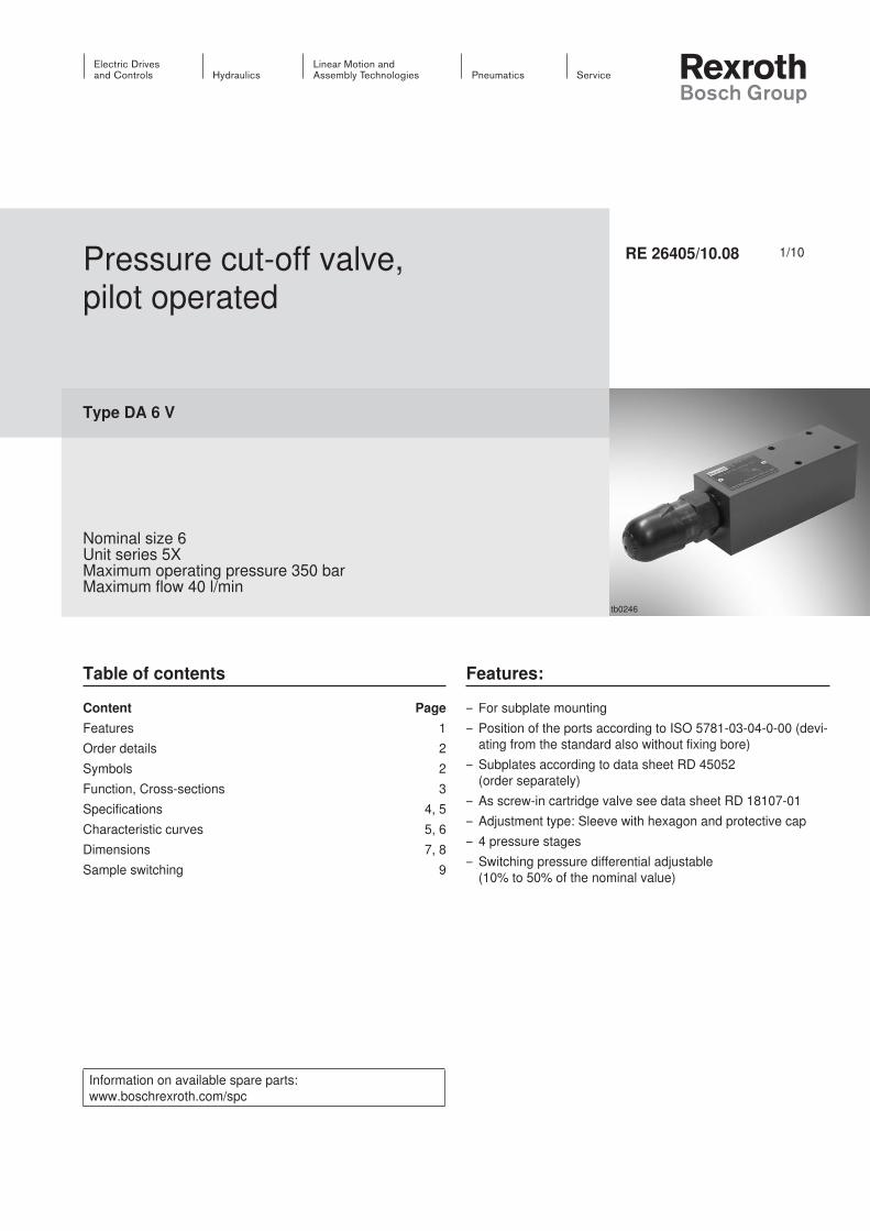
Pressure cut-off valve, pilot operated
Type DA 6 V
Nominal size 6Unit series 5XMaximum operating pressure 350 barMaximum flow 40 l/min
RE 26405/10.08
Table of contents Features:
– For subplate mounting– Position of the ports according to ISO 5781-03-04-0-00 (devi-
ating from the standard also without fixing bore)– Subplates according to data sheet RD 45052
(order separately)– As screw-in cartridge valve see data sheet RD 18107-01– Adjustment type: Sleeve with hexagon and protective cap– 4 pressure stages– Switching pressure differential adjustable
(10% to 50% of the nominal value)
Content PageFeatures 1Order details 2Symbols 2Function, Cross-sections 3Specifications 4, 5Characteristic curves 5, 6Dimensions 7, 8Sample switching 9
tb0246
InhaltTable of contents 1Features: 1Order details 2Symbols 2Function, Cross-sections 3Specifications (Please inquire in case the intended use of unit is outside the given values!) 4Note: Factory setting of the switching pressure differential 5Characteristic curves (measured with HLP46, ϑOil = 40 °C ±5 °C) 5Characteristic curves (measured with HLP46, ϑOil = 40 °C ±5 °C) 6Dimensions: Model “2A” (dimensions in mm) 7Dimensions: Model “2B” (dimensions in mm) 8Sample switching: Type DA 6 VP… 9Notes 10Notes 11Notes 12
2/10 Bosch Rexroth AG Hydraulics DA 6 V RE 26405/10.08
Order details
Pressure cut-off valve Nominal size 6 = 6Pilot controlled = VType of connectionPump connection in channel P (standard) = PPump connection in channel A = AAdjustment typeSleeve with hexagon and protective cap = 2Adjustment on A side = AAdjustment on B side = BUnit series 50 to 59 = 5X (50 to 59: unaltered mounting and connection dimensions)
Further information in the clear text
without designation = without fixing bore
/60 1) = with fixing bore/62 = with fixing bore and
locking pin ISO 8752-3x8-StSealing material
M = NBR seals V = FKM seals
(other seals at request) Attention!
Observe sealing capability of the hy-draulic fluid used!
FS = Freely adjustable switching pressure differential
Pressure range50 = 25 to 50 bar100 = 50 to 100 bar200 = 100 to 200 bar350 = 150 to 350 bar
DA 6 V 2 5X FS *
Preference types and standard units are shown in the EPS (standard price list).
1) Locking pin ISO 8752-3x8-St, Material no. R900005694 (order separately)
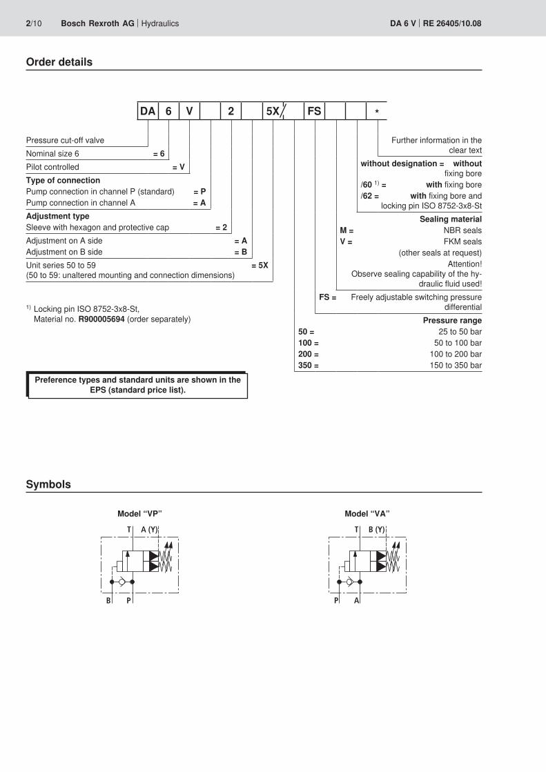
Symbols
Model “VP” Model “VA”
B P
T A (Y)
P A
T B (Y)

10 1
9
8 7 211
TA (Y) P B
6 5 4 3
12
13
Hydraulics Bosch Rexroth AGRE 26405/10.08 DA 6 V 3/10
Function, Cross-sections
Type DA 6 VP…
The type DA 6 V pressure valve is a pilot-operated pressure cut-off valve with continuously adjustable switching pressure differential. It basically consists of pilot control stage and main stage of the screw-in cartridge valve (1), check valve (2) and housing (3).Via connection B, the pump volume flow in P is led into the system accumulator. If the pressure at the consumer in con-nection B exceeds the set upper switching pressure, the pilot control valve opens and control liquid can flow off via con-nection A (Y). The check valve (2) closes the connection of connection B to connection P and the pump volume flow is switched to zero-pressure circulation (from P to T).
Type DA 6 VP– Switch-over of the pump volume flow from P to B (pump → consumer) in P to T (pump → tank)
The pump delivers via the check valve (2) into the hydro sys-tem (P to B). Via control line (4) and bore (5), the pressure present in channel B acts on the pilot control of the screw-in cartridge valve (1). At the same time, the pressure in chan-nel P is - via the bore (7) - existent on the spring-loaded side of the main piston (8). As soon as the upper switch-off pres-sure set via the adjusting spindle (6) in the screw-in cartridge valve (1) has been reached in the hydro system (channel B), the pilot control of the screw-in cartridge valve (1) opens the connection of the spring-loaded side of the main piston (8) to the control line (9) and thus externally via connection A (Y) into the tank. Due to the bore (7), a pressure drop at the main piston (8) results. The main piston (8) raises from the seat and opens the connection P to T. The check valve (2) closes the connection B to P and the pilot control of the screw-in car-tridge valve (1) is kept in an open position by the consumer load pressure in B.– Switch-over of the pump volume flow from P to B (pump → tank) in P to B (pump → consumer).
If, compared with the switch-off pressure, the consumer pres-sure in B has been reduced according to the lower pressure value set at the adjusting spindle (10), the pilot control of the screw-in cartridge valve (1) moves back into its initial position.
Thus, pressure builds up on the spring-loaded side of the main piston (8). This pressure closes the connection P to T by means of the spring (11) and the pump delivers via the check valve (2) into the hydro system from P to B again.
Type DA 6 VAIn this valve type, the pump connection is not designed in P but in A. The valve leads the pump volume flow from A to P or from A to T. The leakage connection is in B (Y).The switching processes comply with the “VP” design (This valve model serves the simpler linkage with multi-station manifold plates).
Notes!– Only indirect pressure limitation function:
There is no direct pressure limitation function of the pump pressure (to the tank), but only an indirect one via the check valve (2) and the control line (4) in the consumer channel.
– Setting the switching pressure differential: In the factory, the valves are with nominal pressure set to a switching pressure differential of approx. 10% to 12%. Set-tings of up to 50% of the nominal pressure are possible.
Upon delivery, the adjusting spindle (6) is set to the mini-mum settable, upper switching pressure, i.e. the adjusting spindle (6) is unscrewed to stop. By screwing the adjust-ing spindle (6) in, the upper switching pressure can be increased.
By screwing the adjusting spindle (10) in, the lower switch-ing pressure is increased and the switching pressure dif-ferential is thus reduced. By screwing the adjusting spindle (10) out, the lower switching pressure is reduced and the switching pressure differential is thus increased.
The pressure setting is secured using clamping screws (12) and lock nuts (13).

4/10 Bosch Rexroth AG Hydraulics DA 6 V RE 26405/10.08
Specifications (Please inquire in case the intended use of unit is outside the given values!)
generalMass kg 2,2Installation position AnyAmbient temperature range °C –30 to +80 (NBR seals)
–20 to +80 (FKM seals)
hydraulicMaximum operat-ing pressure (Type “DA 6 VP”)
– Connection A (Y) (leakage pilot control)
bar 100 1)
– Connection B (consumer) bar 350 (after switch-over P to T)– Connection P (pump) bar 350– Connection T (tank) bar 200
Maximum operat-ing pressure (Type “DA 6 VA”)
– Connection A (pump) bar 350– Connection B (Y) (leakage
pilot control)bar 100 1)
– Connection P (consumer) bar 350 (after switch-over A to T)– Connection T (tank) bar 200
Adjustment pres-sure range 2)
– Pressure stage 50 bar 25 to 50– Pressure stage 100 bar 50 to 100– Pressure stage 200 bar 100 to 200– Pressure stage 350 bar 150 to 350
Maximum volume flow l/min 40Hydraulic fluid Mineral oil (HL, HLP) according to DIN 51524 3); Hydraulic
fluids that are fast biodegradable according to VDMA 24568 (also see RE 90221); HETG (rape seed oil) 3); HEPG (poly glycoles) 4); HEES (synthetic esters) 4); other hydraulic fluids at request
Hydraulic liquid temperature range °C –30 to +80 (NBR seals) –20 to +80 (FKM seals)
Viscosity range – Maximum mm2/s 10 to 800– Recommended mm2/s 20 to 60
Maximum permitted degree of pollution of the hy-draulic fluid purity level according to ISO 4406 (c)
Class 20/18/15 5)
Switching pressure differential 2) % Adjustable from 10% to 50% of the nominal value
1) Attention! The existing pressure adds up to the set pressure! Within the adjustment range, the switching pressure differential remains unchanged!
2) When setting the switching pressure differential, the follow-ing instructions have to be complied with:
– The upper and lower switching point must lie within the adjustment range of the pressure stage (e.g. with a pres-sure stage of 100 bar: upper switching point 100 bar, lower switching point 50 bar ≙ 50% switching pressure differential)
– The lowest switching pressure differential possible largely depends on the system (set pressure, pump and consumer volume flow, accumulator size and initial pressure, line length and resistances, etc.). Here, the valve offers the possibility to optimally adjust the switching pressure differ-ential to the system. For the reasons mentioned above, the smallest settable switching pressure differential of the valve can, however, not always be realized at the system.
– General: Keep the pipe connection between DA valve and hydro accumulator as short and the resistance as low as possible and discharge the control oil (Y) in a depressur-ized form, if possible.
– Information regarding the factory setting of the switching pressure differential see page 5.
3) Suitable for NBR and FKM seals4) Only suitable for FKM seals 5) The purity levels stated for the components need to be
maintained in hydraulic systems. Effective filtration pre-vents faults and at the same time increases the service life of the components.
For selecting the filters, see Data Sheets RE 50070, RE 50076, RE 50081, RE 50086, RE 50087 and RE 50088.

Hydraulics Bosch Rexroth AGRE 26405/10.08 DA 6 V 5/10
Note: Factory setting of the switching pressure differential– In the factory, the valves are with nominal pressure set to a
switching pressure differential of approx. 10% to 12% and they are delivered in a depressurized condition (adjusting spindle (6) unscrewed to stop, see page 3).
– The setting is made with nominal pressure, a pump volume flow of approx. 10 l/min and a consumer volume flow of ap-prox. 2 l/min.
– With different system conditions (particularly with high pump and consumer volume flow), higher switching pres-sures could result. Here, the valve offers the possibility to optimally adjust the switching pressure differential to the system.
Characteristic curves (measured with HLP46, ϑOil = 40 °C ±5 °C)
Volume flow in l/min →
Volume flow in l/min →
Volume flow in l/min →
Volume flow in l/min →
Pres
sure
diff
eren
ce in
bar
→Pr
essu
re d
iffer
ence
in b
ar →
Pres
sure
diff
eren
ce in
bar
→Pr
essu
re d
iffer
ence
in b
ar →
∆p-qV characteristic curves, circulation pressure – model “VP” (P to T)
∆p-qV characteristic curves, circulation pressure – model “VA” (A to T)
Model “VP2B”
Model “VA2B”
Model “VP2A”
Model “VA2A”
Note!– The characteristic curves have been measured with exter-
nal, depressurized control oil return (circulation pressure).– The characteristic curves are valid for output pres-
sure = 0 bar over the whole volume flow range.
00
5 10 15 20 25 30 35 40
10
2
4
6
8
12
14
00
5 10 15 20 25 30 35 40
10
2
4
6
8
12
14
00
5 10 15 20 25 30 35 40
10
2
4
6
8
12
14
00
5 10 15 20 25 30 35 40
10
2
4
6
8
12
14

6/10 Bosch Rexroth AG Hydraulics DA 6 V RE 26405/10.08
Characteristic curves (measured with HLP46, ϑOil = 40 °C ±5 °C)
Volume flow in l/min →
Volume flow in l/min →
Volume flow in l/min →
Volume flow in l/min →
Pres
sure
diff
eren
ce in
bar
→Pr
essu
re d
iffer
ence
in b
ar →
Pres
sure
diff
eren
ce in
bar
→Pr
essu
re d
iffer
ence
in b
ar →
∆p-qV characteristic curves via check valve – model “VP” (P to B)
∆p-qV characteristic curves via check valve – model “VA” (A to T)
Model “VP2B”
Model “VA2B”
Model “VP2A”
Model “VA2A”
Note!– The characteristic curves have been measured with exter-
nal, depressurized control oil return (circulation pressure).– The characteristic curves are valid for output pres-
sure = 0 bar over the whole volume flow range.
00
5 10 15 20 25 30 35 40
10
2
4
6
8
12
14
00
5 10 15 20 25 30 35 40
10
2
4
6
8
12
14
00
5 10 15 20 25 30 35 40
10
2
4
6
8
12
14
00
5 10 15 20 25 30 35 40
14
2
4
6
8
10
12
Rt 4
0,01/100
F1 F2
F3F4
AT
B
PG
71130 1
16640
30
51
6,5
1 2
3 4
44
Hydraulics Bosch Rexroth AGRE 26405/10.08 DA 6 V 7/10
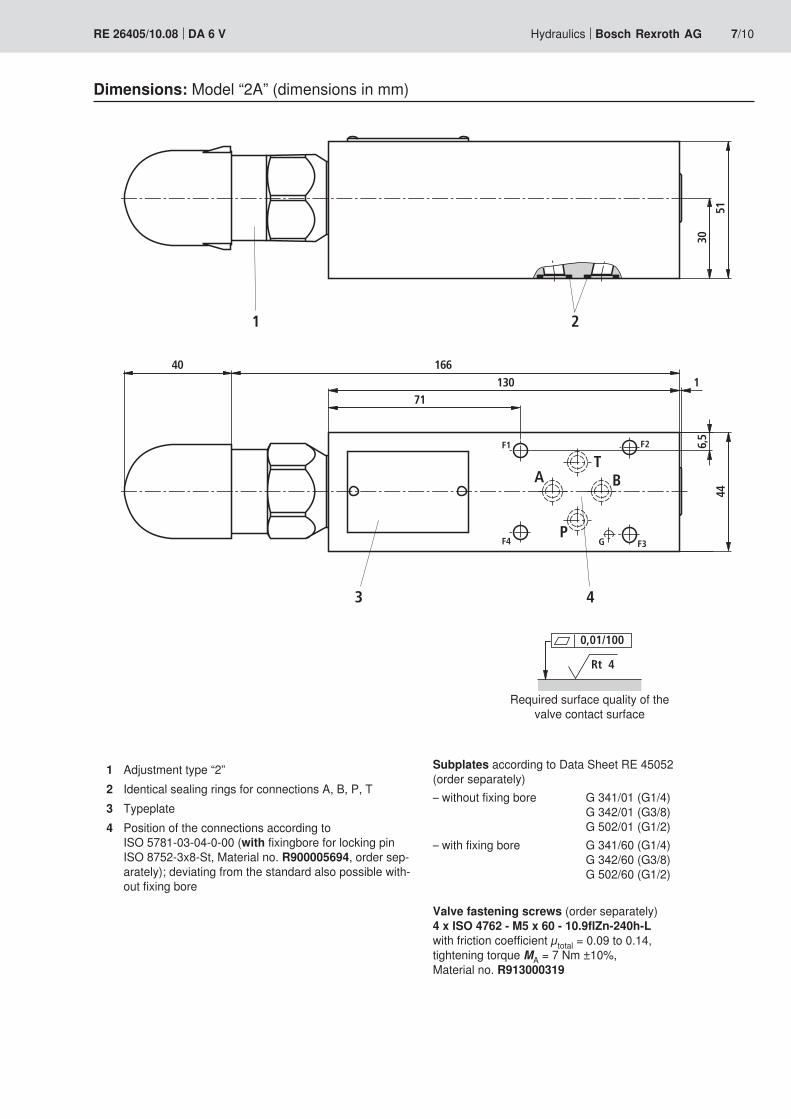
Dimensions: Model “2A” (dimensions in mm)
Subplates according to Data Sheet RE 45052 (order separately)– without fixing bore G 341/01 (G1/4) G 342/01 (G3/8) G 502/01 (G1/2)– with fixing bore G 341/60 (G1/4) G 342/60 (G3/8) G 502/60 (G1/2)
Valve fastening screws (order separately)4 x ISO 4762 - M5 x 60 - 10.9flZn-240h-L with friction coefficient µtotal = 0.09 to 0.14, tightening torque MA = 7 Nm ±10%, Material no. R913000319
Required surface quality of the valve contact surface
1 Adjustment type “2”2 Identical sealing rings for connections A, B, P, T3 Typeplate4 Position of the connections according to
ISO 5781-03-04-0-00 (with fixingbore for locking pin ISO 8752-3x8-St, Material no. R900005694, order sep-arately); deviating from the standard also possible with-out fixing bore

F1 F2
F3F4
AT
B
PG
201301
166 40
3051
6,5
12
34
44
8/10 Bosch Rexroth AG Hydraulics DA 6 V RE 26405/10.08
Dimensions: Model “2B” (dimensions in mm)
Subplates according to Data Sheet RE 45052 (order separately)– without fixing bore G 341/01 (G1/4) G 342/01 (G3/8) G 502/01 (G1/2)– with fixing bore G 341/60 (G1/4) G 342/60 (G3/8) G 502/60 (G1/2)
Valve fastening screws (order separately)4 x ISO 4762 - M5 x 60 - 10.9flZn-240h-L with friction coefficient µtotal = 0.09 to 0.14, tightening torque MA = 7 Nm ± 10%, Material no. R913000319
Required surface quality of the valve contact surface
1 Adjustment type “2”2 Identical sealing rings for connections A, B, P, T3 Typeplate4 Position of the connections according to
ISO 5781-03-04-0-00 (with fixingbore for locking pin ISO 8752-3x8-St, Material no. R900005694, order sep-arately); deviating from the standard also possible with-out fixing bore
Rt 4
0,01/100

Hydraulics Bosch Rexroth AGRE 26405/10.08 DA 6 V 9/10
Sample switching: Type DA 6 VP…
Information regarding the use:Keep the pipe connection between pressure cut-off valve and hydro accumulator as short and the resistance as low as possible!
Attention!– Accumulators may only be operated with suitable accumu-
lator safety equipment!– There is no direct pressure limitation function of the pump
pressure (to the tank), but only an indirect one via the check valve and the control line in the consumer channel (see page 3).
Hydo system with pressure accumulator Hydo system with high and low pressure pump
M
T
B
P A T
1
S
P
P A T
B
1
2 3
1 To the consumer2 High-pressure pump3 Low-pressure pump

Bosch Rexroth AG HydraulicsZum Eisengießer 197816 Lohr am Main, Germany Phone +49 (0) 93 52 / 18-0 Fax +49 (0) 93 52 / 18-23 [email protected] www.boschrexroth.de
© All rights Bosch Rexroth AG, including applications for property rights. All powers of disposal, such as rights of duplication and transfer, lie with us.The data specified above only serve to describe the product. It cannot be used to derive a particular property or suitability for a specific use. The information conveyed does not relieve the user of making own evaluations and performing own inspections. It must be remembered that our products are subject to a natural process of wear and aging.
10/10 Bosch Rexroth AG Hydraulics DA 6 V RE 26405/10.08
Notes

Bosch Rexroth AG HydraulicsZum Eisengießer 197816 Lohr am Main, Germany Phone +49 (0) 93 52 / 18-0 Fax +49 (0) 93 52 / 18-23 [email protected] www.boschrexroth.de
© All rights Bosch Rexroth AG, including applications for property rights. All powers of disposal, such as rights of duplication and transfer, lie with us.The data specified above only serve to describe the product. It cannot be used to derive a particular property or suitability for a specific use. The information conveyed does not relieve the user of making own evaluations and performing own inspections. It must be remembered that our products are subject to a natural process of wear and aging.
Hydraulics Bosch Rexroth AGRE 26405/10.08 DA 6 V 11/10
Notes

Bosch Rexroth AG HydraulicsZum Eisengießer 197816 Lohr am Main, Germany Phone +49 (0) 93 52 / 18-0 Fax +49 (0) 93 52 / 18-23 [email protected] www.boschrexroth.de
© All rights Bosch Rexroth AG, including applications for property rights. All powers of disposal, such as rights of duplication and transfer, lie with us.The data specified above only serve to describe the product. It cannot be used to derive a particular property or suitability for a specific use. The information conveyed does not relieve the user of making own evaluations and performing own inspections. It must be remembered that our products are subject to a natural process of wear and aging.
12/10 Bosch Rexroth AG Hydraulics DA 6 V RE 26405/10.08
Notes