NOTE TO USERS - Concordia University · Figure 2.4: Invoking the LoanAssesor Service in the Sample...
101
NOTE TO USERS This reproduction is the best copy available. ® UMI
Transcript of NOTE TO USERS - Concordia University · Figure 2.4: Invoking the LoanAssesor Service in the Sample...

NOTE TO USERS
This reproduction is the best copy available.
®
UMI


Automatic Quality of Service Adaptation for Composite
Web Services
Ming Qiao
A Thesis
in
The Department
of
Electrical and Computer Engineering
Presented in Partial Fulfillment of the Requirements for the Degree of Master of Applied Science at
Concordia University Montreal, Quebec, Canada
January 2009
© Ming Qiao, 2009

1*1 Library and Archives Canada
Published Heritage Branch
395 Wellington Street OttawaONK1A0N4 Canada
Bibliotheque et Archives Canada
Direction du Patrimoine de I'edition
395, rue Wellington Ottawa ON K1A0N4 Canada
Your We Votre reference ISBN: 978-0-494-63228-4 Our file Notre reference ISBN: 978-0-494-63228-4
NOTICE: AVIS:
The author has granted a nonexclusive license allowing Library and Archives Canada to reproduce, publish, archive, preserve, conserve, communicate to the public by telecommunication or on the Internet, loan, distribute and sell theses worldwide, for commercial or noncommercial purposes, in microform, paper, electronic and/or any other formats.
L'auteur a accorde une licence non exclusive permettant a la Bibliotheque et Archives Canada de reproduire, publier, archiver, sauvegarder, conserver, transmettre au public par telecommunication ou par Nnternet, preter, distribuer et vendre des theses partout dans le monde, a des fins commerciales ou autres, sur support microforme, papier, electronique et/ou autres formats.
The author retains copyright ownership and moral rights in this thesis. Neither the thesis nor substantial extracts from it may be printed or otherwise reproduced without the author's permission.
L'auteur conserve la propriete du droit d'auteur et des droits moraux qui protege cette these. Ni la these ni des extraits substantiels de celle-ci ne doivent etre imprimes ou autrement reproduits sans son autorisation.
In compliance with the Canadian Privacy Act some supporting forms may have been removed from this thesis.
While these forms may be included in the document page count, their removal does not represent any loss of content from the thesis.
Conformement a la loi canadienne sur la protection de la vie privee, quelques formulaires secondaires ont ete enleves de cette these.
Bien que ces formulaires aient inclus dans la pagination, il n'y aura aucun contenu manquant.
1*1
Canada

Abstract
Automatic Quality of Service Adaptation for Composite Web Services
Ming Qiao
Quality of Services (QoS) management has become an important issue for Web services.
Indeed, QoS is becoming a crucial and a distinguishing criterion among functionally
equivalent Web services. QoS Management consists of two complementary tasks:
monitoring and adaptation. Both are very challenging because of the unpredictable and
dynamic nature of Web service composition. We are motivated to solve the QoS problem
by taking advantage of some characteristics of composite Web services, such as their
similarity to traditional workflows.
In this thesis, we propose a broker based architecture that enables dynamic QoS
monitoring and adaptation for composite Web services. Our approach consists of
dynamically changing the execution paths of composed Web services by instrumenting
the BPEL process. A new construct flexPath is introduced for supporting alternate
execution paths definition in BPEL. We developed a BPEL compiler allowing automatic
instrumentation for BPEL definition files. The BPEL process is deployed using the
instrumented definition files in order to interact with the QoS broker during execution.
The QoS broker is a key component in our architecture and is responsible of monitoring
the QoS and managing the adaptation. We propose a broker that enables runtime
monitoring of QoS, prediction of potential QoS violation, and the selection of the best
execution path of the process in order to improve QoS when needed.

We developed a prototype to evaluate our proposed architecture. A case study is also
presented through an example BPEL process and a number of partner Web services. The
performance of the QoS adaptation has been analyzed and the results showed that the
QoS of the BPEL process has been considerably adapted and improved comparing to the
original one. In addition, we analyzed the major factors that affect the performance of
our prototype tool.
IV

ACKNOWLEDGEMENTS
I wish to express my gratitude and thanks to my supervisors Dr. Ferhat Khendek and Dr.
Rachida Dssouli. Thank you for providing help, support, and assistance all the time,
especially during the last stage of the research when email was the only method of
communications. Dr. Khendek, I have learned a lot from your suggestions, ideas, and
teachings. Your perpetual energy and enthusiasm in research have always motivated me.
Dr. Dssouli, thank you for your guidance and advices. Your understanding and
encouragement helped me go through the difficult times. I also want to thank Dr. Roch
Glitho for your valuable comments during the TSE Lab meetings. You helped me explore
research from a different perspective, which is more industry-oriented.
I would like to take this opportunity to thank Dr. Mohamed Adel Serhani, Joana Sequeira
Torreira da Silva, and everyone in the TSE lab. Thank you for all the fruitful discussions
which inspired me a lot. I appreciate all the help you provided from paper writing to
software tools.
I would also like to acknowledge the financial support from Natural Sciences and
Engineering Research Council of Canada (NSERC), Ericsson Canada Inc. and from
PROMPT Quebec.
This thesis would not have been possible without the immense support I have been
getting from my family. Thank you for believing in me from the beginning to the end
without any doubt. The deepest gratitude goes to my wife and my parents for all your
help, caring and love. To you, I dedicate this work.
Table of Contents
LIST OF FIGURES xi
LIST OF ACRONYMS AND ABBREVIATIONS ix
CHAPTER 1: INTRODUCTION 1
1.1 INTRODUCTION TO THE RESEARCH DOMAIN 1
1.2 PROBLEM STATEMENT 3
1.3 GOALS AND MOTIVATIONS 4
1.4 THESIS CONTRIBUTIONS 5
1.5 ORGANIZATION OF THE THESIS 5
CHAPTER 2: WEB SERVICES: COMPOSITION, ADAPTATION AND QOS 8
2.1 WEB SERVICES 8
2.1.1 Definition and Architecture of Web Services 8
2.1.2 Web Service Technology Stacks 10
2.1.2.1 SOAP: Simple Object Access Protocol 12
2.1.2.2 WSDL: Web Services Description Language 12
2.1.2.3 UDD1: Universal Description, Discovery, and Integration 12
2.1.3 Web Service Composition and BPEL 13
2.2 QoS FOR WEB SERVICES 18
2.2.7 QoS Specifications 19
2.2.2 Managing QoS for Web Services 20
2.2.3 QoS of Composite Web Services 22
2.3 QoS ADAPTATION 24
2.4 SUMMARY 26
vi

CHAPTER 3: STATE-OF-THE-ART IN QOS ADAPTATION FOR WEB SERVICES 27
3.1 QOS-ADAPTIVE WEB SERVICES 28
3.1.1 Web Service Replication 28
3.1.2 Web Service Relocation 30
3.1.3 Dynamic Web Service Invocation 31
3.2 QOS-ADAPTIVE WORKFLOWS 33
3.3 QoS ADAPTATION FOR COMPOSITE WEB SERVICES 35
3.3.1 Dynamic Partner Web Services Re-selection 35
3.3.2 Dynamic Modification of Composition Schema 38
3.3.3 Automated Planning 40
3.3.4 AOP Method 41
3.4 A BROKER-BASED ARCHITECTURE OF QOS MANAGEMENT FOR WEB SERVICES 42
3.5 SUMMARY 44
CHAPTER 4: AN ARCHITECTURE FOR QOS ADAPTATION FOR COMPOSITE WEB SERVICES 46
4.1 FLEXPATH: AN EXTENSION FOR BPEL 46
4.2 THE OVERALL ARCHITECTURE FOR QOS-ADAPTIVE COMPOSITE WEB SERVICES 48
4.3 PROCEDURE OF QOS ADAPTATION BASED ON THE PROPOSED ARCHITECTURE 51
4.4 SUMMARY 53
CHAPTER 5: BPEL PROCESS INSTRUMENTATION 54
5.1 AUTOMATIC INSTRUMENTATION USING JDOM 54
5.2 INSTRUMENTATION OF PARTNERLINKTYPE AND PARTNERLINK FOR THE BROKER 56
5.3 INSTRUMENTATION OF PROBES 57
5.4 INSTRUMENTATION OF PATHSELECTOR 59
5.5 SUMMARY ,61
vii

CHAPTER 6: A QOS BROKER FOR AUTOMATIC MONITORING AND ADAPTATION 62
6.1 TOPOLOGY INTERPRETER 62
6.2 QoS MONITOR 65
6.3 QoS ADAPTOR 66
6.4 SUMMARY 68
CHAPTER 7: A PROTOTYPE TOOL AND CASE STUDY 69
7.1 IMPLEMENTATION OF PROTOTYPE TOOL 69
7.1.1 Implement the BPEL Compiler for Automatic Instrumentation 70
7.1.2 Implement the QoS Broker 70
7.2 A CASE STUDY 74
7.3 SUMMARY 79
CHAPTER 8: CONCLUSION 81
8.1 SUMMARY OF CONTRIBUTIONS 81
8.2 FUTURE WORK 82
REFERENCES 84
viii

List of Figures
Figure 2.1: Web Service Architectural Model 9
Figure 2.2: Web Service Technology Stacks (taken from [W3C 2004]) 11
Figure 2.3: A Sample BPEL Process Developed by Active Endpoints 17
Figure 2.4: Invoking the LoanAssesor Service in the Sample BPEL Process 18
Figure 2.5: Web Service Composition Patterns (taken from [Jaeger 2004]) 23
Figure 3.1: Web Service Replication Using a Gateway 28
Figure 3.2: Web Service Replication without Using a Gateway 29
Figure 3.3: Web Service Relocation 30
Figure 3.4: Dynamic Web Service Invocation 32
Figure 3.5: Dynamic Partner Web service Re-selection 36
Figure 3.6: Dynamic Modification of Composition Schema at Run-time 39
Figure 3.7: Broker-based Architecture for QoS-enabled Web services 43
Figure 4.1: Defining Alternate Execution Path in BPEL 47
Figure 4.2: Overall Architecture for QoS-adaptive Composite Web Services 49
Figure 4.3: Component Interaction of Proposed Architecture 51
Figure 5.1: Architecture of the BPEL compiler 55
Figure 5.2: Example of partnerLink for a QoS Broker 56
Figure 5.3: Example of partnerLinkType for a QoS Broker 57
Figure 5.4: Example of Probe Instrumentation 58
Figure 5.5: Design of the Probe 59
Figure 5.6: Instrumentation of Probes and pathSelectors 60
ix

Figure 5.7: Design of the pathSelector 61
Figure 6.1: Modeling a <sequence> Activity 64
Figure 6.2: Modeling a <flexPath> 65
Figure 6.3: Determine the Probability of Violation of Response Time 67
Figure 7.1: Part of WSDL of the QoS Broker 70
Figure 7.2: Class Definition of Sections in Topology Interpreter 73
Figure 7.3: The Instrumented Example BPEL Process 74
Figure 7.4: Modeling the Example BPEL Process in the Topology Interpreter 75
Figure 7.5: QoS Statistics of the Original BPEL Process 76
Figure 7.6: QoS Statistics of the Original BPEL Process with f = 100% 77
Figure 7.7: QoS Statistics of the QoS- adaptable Process with f = 90% 78
Figure 7.8: QoS Statistics of the QoS- adaptable Process with f = 80% 78
X

List of Acronyms and Abbreviations
AOP:
BPEL:
BPML:
CORBA:
DOM:
DTD:
FTP:
HTTP:
HTN:
HOP:
JMS:
OASIS:
OS:
QOS:
RAM:
RMI:
RPC:
SMTP:
SOA:
SOAP:
UDDI:
Aspect-Oriented Programming
Business Process Execution Language
Business Process Modeling Language
Common Object Requesting Broker Architecture
Document Object Model
Document Type Definition
File Transfer Protocol
Hypertext Transfer Protocol
Hierarchical Task Network
Internet Inter-Orb Protocol
Java Message Service
Organization for the Advancement of Structured Information Standards
Operation System
Quality of Service
Random-access memory
Remote Method Invocation
Remote Procedure Call
Simple Mail Transfer Protocol
Service-Oriented Architecture
Simple Object Access protocol
Universal Description, Discovery, and Integration

W3C: World Wide Web Consortium
WS: Web Service
WSCI: Web Services Choreography Interface
WSDL: Web Services Description Language
WSFL: Web Services Flow Language
WWW: World Wide Web
XML: Extensible Markup Language
Xll

Chapter 1
Introduction
This chapter presents a brief introduction to the domain, the problem statement, the
motivations and the contributions of this thesis.
1.1 Introduction to the Research Domain
The concept of service is now familiar to the computer science community. Thinking in
terms of service offers a new point of view for designing computer applications. A rough
definition of service would be to provide a "black-box" application that can be invoked
by humans and other applications. SOA (Service-Oriented Architecture) defines how
services communicate with each other. OASIS (Organization for the Advancement of
Structured Information Standards) defines SOA as a paradigm for organizing and
utilizing distributed capabilities that may be under the control of different ownership
domains [OASIS 2006]. Based on SOA, a service exposes its functionalities to other
services through interfaces by using defined protocols. The services are loose-coupled
which means the interaction among services is independent to the underlying
technologies used by implementing the services such as the operation systems,
programming languages, etc.
Among many approaches that can implement the service-oriented architecture, for
instance, Jini, CORBA, etc., Web service technology has gained broad academic and
industry acceptance. An application can be defined as a Web service which is accessible
via standard internet protocols. Web service protocols are defined on top of a common
data exchange standard which is XML. These protocols allow the communication among
services to be platform independent. More specifically, how to interact with a Web
service is defined by its messages and operations rather than its implementation details.
This makes achieving the loose-coupling among Web services easier. In recent years,
Web service has become a comprehensive solution for helping enterprises to create
reusable services.
One of the key aspects of Web services is that a service can be composed of other
services. Assembling multiple Web services into a new service is called Web service
composition [Srivastava 2003] [Aalst 2003]. The composition can be defined using Web
service composition languages. Defining a composition includes providing logics of
interactions between the composed service and the Web services that participate in it
[Khalaf 2003]. Some composition languages are workflow-based which makes the task
of composing Web services similar to defining a workflow.
Since Web services wrap applications into services, the QoS of Web services would be
one of the major concerns for service clients. QoS of Web services includes service
quality such as latency, availability, timeliness and reliability [Chen 2003]. Service
providers face challenges to guarantee the end-to-end QoS for their Web services given
the dynamic and the flexible environments of service execution. Therefore, it is critical
for them to have QoS management support to assure the QoS provided to the clients.
1.2 Problem Statement
As mentioned in the previous section, QoS plays an important role for both service
providers and requestors. A Web service should not only be manageable from the
functionality perspective but also from non-functional aspects perspective. However,
QoS for Web services is not managed in a well-structured manner nowadays. There are
several aspects that should be included in a successful QoS management architecture.
QoS specification, measurement, selection, monitoring, verification, negotiation, and
adaptation are among those aspects.
A composite Web service is a special kind of Web service. Besides the issue of having a
well-defined QoS management architecture, it is also facing its own QoS challenges
because of its composite nature. For instance, figuring out the relationship between the
composite QoS and the QoS of participating services is an important question that needs
to be addressed.
Among many aspects in the QoS management, QoS adaptation is a topic that has not
been studied thoroughly. In the Web service domain, this actually means the building of a
Web service, which is QoS-adaptable. The QoS of a Web service constantly changes
during run-time due to the dynamic variations of, for example, resource availability,
traffic, etc. This kind of fluctuation can make the QoS completely unacceptable.
3

Therefore a QoS-adaptable Web service is defined as a service that is able to adapt to the
QoS variation (e.g. degradation) at run-time. This is exactly the problem we are
addressing in this thesis: define an architecture that enables automatic QoS adaptation for
Web services. More specifically, we focus on composite Web services.
1.3 Goals and Motivations
Existing Web service standards do not support QoS adaptation. A QoS-adaptive Web
service is capable of maintaining its QoS at an acceptable level. Without the QoS
adaptability, QoS contracts would be meaningless to the clients, especially in Web
services' rapid changing environment.
There are several goals that we want to achieve in this thesis. First, the adaptation should
be automatic, which means it should happen without human's intervention. The
procedure of monitoring QoS, making decision of when to trigger the adaptation, and the
action of adaptation should all be executed automatically.
Second, we believe that the QoS adaptation should be triggered as soon as the QoS
violation is expected to happen at run-time. The point here is the adaptation should not
wait until the QoS requirement has already been violated. In other words, our goal is to
build a pro-active adaptation technique.
The third goal to achieve is that the QoS adaptation should not stop the composite Web
service execution. This is a drawback of some existing adaptation techniques. For
example in [Canfora 2005], the service execution has to stop in order to re-plan the
composition for improving the QoS. We believe that a good adaptation scheme for Web
4
services should be able to dynamically improve the QoS of the current running instance
without stopping it.
1.4 Thesis Contributions
To solve aforementioned issues, we propose an architecture that enables automatic QoS
monitoring and adaptation by dynamically changing the execution paths of composed
Web services when necessary. Our main contributions include:
1. A broker-based architecture supporting QoS-adaptable composite Web service
2. A QoS broker design which is capable of interpreting the schema of composite Web
services, monitoring the QoS, predicting the potential QoS violation, and triggering
QoS adaptation.
3. A new activity for BPEL called "flexPath" which enables the definition of alternate
execution path in BPEL. Note that BPEL is a language for defining Web services
composition that will be introduced in the next chapter.
4. A mechanism for automatically instrumenting BPEL processes for the purpose of
adaptation.
1.5 Organization of the Thesis
The second chapter gives an overview of Web services, the QoS issue for Web services,
and the QoS adaptation in particular. We introduce the Web service paradigm in general
at the beginning. Then, we discuss in detail Web services composition. We discuss the
5
issue of managing QoS for Web services in the second half. Similarly, we discuss the
issue for Web services in general first before moving to the case of composite Web
services. Finally, we discuss the problem of QoS adaptation.
The third chapter studies the related work in the area of QoS adaptation. We discuss a
broker-based approach to manage QoS for Web services, on which our proposed
architecture is based. Then, we introduce approaches of creating flexible workflows. We
introduce and discuss related work on QoS adaptation, including approaches for general
Web services and composite Web services. We also discuss a broker-based WS-QoS
management architecture which provides a foundation to our work. A summary of the
state-of-the-art in this area concludes this chapter.
The fourth chapter describes our proposed architecture in detail. We introduce the main
components of the architecture and explain their respective roles. We also describe the
procedure of the QoS adaptation for a typical composite Web service execution.
The fifth chapter introduces our proposed approach of BPEL instrumentation. The
mechanism of automatic instrumentation is described in this chapter as well as how to
instrument different parts of a BPEL description.
The sixth chapter describes our proposed QoS broker design. We explain the design of
the three main modules in the QoS broker: the Topology Interpreter, the QoS Monitor,
and the QoS Adaptor. For each module: the detailed design of the main features, the
interface and interaction with other components are introduced and discussed.

The prototype implementation, a case study, and the analysis are provided in the seventh
chapter. This chapter discusses the implementation architecture of the prototype tool and
explains in detail a case study. Details on the test environment, some performance
measurements and analysis are also provided.
The last chapter concludes the thesis by summarizing the contributions and pointing out
possible future work.
7
Chapter 2
Web Services: Composition, Adaptation and QoS
This chapter contains three sections. Section 1 discusses the Web service paradigm
including Web service composition. Section 2 studies the QoS issue for Web services.
Section 3 extends the discussion into one of the most important QoS aspects, i.e. QoS
adaptation.
2.1 Web Services
Web service technology allows different applications to be exposed as services via the
network and interact with each other through standardized XML-based techniques. In this
section, we will answer the following questions: What is Web service? What is the
architecture of Web services? What are the major standards of Web services and what are
their roles respectively?
2.1.1 Definition and Architecture of Web Services
Based on the definition by W3C [W3C 2004], a Web service is a software system
designed to support interoperable machine-to-machine interaction over a network. It has
an interface described in a machine-processable format, for instance WSDL (Web
Services Description Language). Other systems interact with the Web service in a manner
prescribed by its description using SOAP (Simple Object Access protocol) messages,
8

typically conveyed using HTTP with an XML serialization in conjunction with other
Web-related standards.
The concept of Web service is always being confused with Web applications. The main
difference between them is: Web services are designed for machine-use, while Web
applications, such as a JavaScript application which can be accessed from a Web page,
are mainly designed for human-use. Due to the fact that Web services are platform-
independent and can be requested and invoked directly by other applications, they are
generally more modular, self-aware, reusable, and manageable than Web applications
[Papazoglou 2004].
Figure 2.1 illustrates the Web service architecture. There are three main components in
this architecture: service registry which acts as a searchable directory for published
service interfaces, service provider who creates, implements, and announces the service,
and service requestor who uses the service.
Service Registry (UDDI)
\
•Bind-
\
* Service Provider
Figure 2.1: Web Service Architectural Model
9

In this architecture, the service providers describe the interfaces and properties of their
Web services by using WSDL. They then register the services into service registries
using UDDI (Universal Description, Discovery, and Integration). Service registries act as
Yellow Pages allowing the service requestors to discover services they want. After
finding a service, the requestor obtains the necessary information to access the service
such as the address of the service's WSDL file from the registry. Then, the requestors can
invoke the services using the SOAP in either asynchronous messaging or RPC (Remote
Procedure Call) mode.
As illustrated in Figure 2.1, the operations among the three roles in the Web service
architecture are defined as publish, find, and bind:
1. Publish: This operation consists of two parts: defining the service interface through
WSDL by the service provider, and registering the service into service registry
through UDDI.
2. Find: The service requestor uses this operation to find the service. It contains
discovering the service from UDDI, and finding the location for service invocation.
3. Bind: The actual run-time service invocation happens on the bind operation. In this
operation, the service requestor initiates the request to the service provider, reaches an
agreement with the provider about service running, and invokes the service.
2.1.2 Web Service Technology Stacks
Web services involve a lot of technologies. W3C illustrates the Web service technology
stacks as in Figure 2.2 in its working group note [W3C 2004]. A number of technologies
10

from different layers have become key Web service standards which define how to
design, deploy, and run Web services.
s E C u R
T Y
OB CI
- I <D n •a 3 o_ o n
F*
p in
3 u
Processes D'SiDvery. Angrerption Choreography
Descriptions . " I . . - • • I . • * ! • I • 1
Messages
SOAP Extensions Reliability, Correlation, Transactions.
SOAP
Communications HTTP, SMTP, FTP, JMS, HOP,
Figure 2.2: Web Service Technology Stacks (taken from [W3C 2004])
Figure 2.2 provides a bottom-up view for Web service technologies. Starting from the
bottom layer, many ubiquitous network protocols can be used as the communication
protocols to carry Web services. This is one of the most important advantages of Web
services that they are able to be accessed over different networks. From this layer up, a
few of XML-based standards including SOAP, WSDL, and UDDI define the Web service
messaging, description, and discovery. They are now well-accepted as core standards of
Web services. The highest layer consists of standards that define the logics and strategies
of business processes, such as languages for Web service compositions. In this section,
we discuss the core standards in detail: SOAP, WSDL, and UDDI.
n
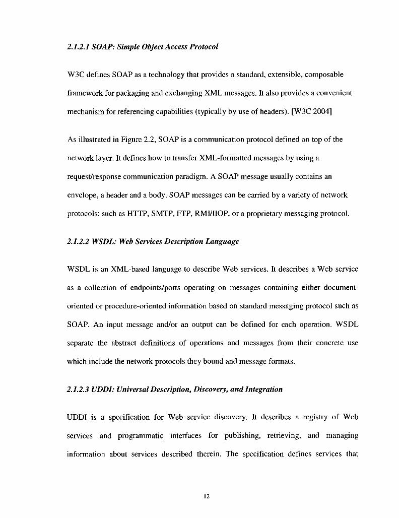
2.1.2.1 SOAP: Simple Object Access Protocol
W3C defines SOAP as a technology that provides a standard, extensible, composable
framework for packaging and exchanging XML messages. It also provides a convenient
mechanism for referencing capabilities (typically by use of headers). [W3C 2004]
As illustrated in Figure 2.2, SOAP is a communication protocol defined on top of the
network layer. It defines how to transfer XML-formatted messages by using a
request/response communication paradigm. A SOAP message usually contains an
envelope, a header and a body. SOAP messages can be carried by a variety of network
protocols: such as HTTP, SMTP, FTP, RMI/IIOP, or a proprietary messaging protocol.
2.1.2.2 WSDL: Web Services Description Language
WSDL is an XML-based language to describe Web services. It describes a Web service
as a collection of endpoints/ports operating on messages containing either document-
oriented or procedure-oriented information based on standard messaging protocol such as
SOAP. An input message and/or an output can be defined for each operation. WSDL
separate the abstract definitions of operations and messages from their concrete use
which include the network protocols they bound and message formats.
2.1.2.3 UDDI: Universal Description, Discovery, and Integration
UDDI is a specification for Web service discovery. It describes a registry of Web
services and programmatic interfaces for publishing, retrieving, and managing
information about services described therein. The specification defines services that
12

support the description and discovery of (1) businesses, organizations, and other Web
services providers, (2) the Web services they make available, and (3) the technical
interfaces which may be used to access and manage those services. [OASIS 2004]
2.1.3 Web Service Composition and BPEL
One of the main advantages of Web services is the possibility of composing them for
creating new ones. The logic of a composite Web service is implemented by individual
services which participate in the composition. This is similar to the traditional workflow
which is defined as an aggregation of activities [Dustdar 2005].
Defining Web service composition is still an open research area where a large number of
approaches have been proposed. Many of composition approaches use programming
languages to link Web services and define the transition among them. [Milanovic 2004]
points out that a composition approach should meet several requirements including
nonfunctional properties, connectivity, correctness, scalability and automaticity:
1. Nonfunctional properties: Nonfunctional properties such as QoS should be addressed
in the composition description since the composing services are running in a highly
dynamic distributed environment. Unfortunately, QoS specifications have not been
integrated into most of today's approaches. When composing a service, these
approaches only focus on how to meet the user's functional requirement.
2. Connectivity: A composition links multiple Web services together. These Web
services can be running in different platforms or connected through different network
technologies. Connectivity refers to the messaging and interfacing among the
13

composed service and partner services. A good composition approach should provide
seamless message exchanging among different parties in the composition.
3. Correctness: The correctness means the truthfulness of the composed service's
specifications and properties, such as security or dependability.
4. Scalability: The composition framework should scale with the number of the
participating Web services in the composition.
5. Automaticity: The composition should be done with minimum human intervention. It
is a complex topic about how to achieve high level of automaticity on service
composition. Most existing mechanisms such as BPEL are still considered as manual
composition.
Existing well-known Web service composition languages include BPEL, WSFL,
XLANG, WSCI, and BPML. WSFL (Web Service Flow Language) which is proposed by
IBM and XLANG which is proposed by Microsoft are considered as the first generation
of the composition languages. They are similar in terms of composition functionality, but
they are not compatible. Researchers from IBM, Microsoft, BEA Systems, SAP, and
Siebel Systems then developed the second generation composition language called BPEL
which stands for Web Services Business Process Execution Language. This language
combines WSFL, XLANG and BEA Systems' WSCI (Web Services Choreography
Interface). It is now seen as the de-facto standard of the composition language.
BPEL is an XML language that specifies Web service based business process behavior.
Multiple Web services can be composed into a BPEL process which can be deployed as a
new Web service. The BPEL process is defined to achieve a certain task by interacting
14

with different Web services. These Web services are called partners in BPEL. The
designer needs to define interactions between the process Web service and each partner
Web service. In BPEL, this interaction is modeled as partnerLinkTypes. A
parterLinkType normally defines the roles of two partners and the relationship between
them. Note that the BPEL process itself is considered as a partner as well.
BPEL can define two different types of processes: abstract process and executable
process. An abstract process is only a conceptual definition of a process which is not
meant to be executed. It is not used much so far. In this thesis, when talking about BPEL
processes we always refer to executable processes.
The BPEL process description is defined in an XML file which conforms to the BPEL
standard. The latest BPEL standard is WS-BPEL 2.0 standardized by OASIS at 2007
which is defined in [OASIS 2007]. This standard specifies a process schema as a set of
activities connected by links. BPEL defines two types of activities: structured activities
and basic activities.
1. Structured Activities:
• Flow: defines parallel and control dependencies processing
• ForEach: defines processing multiple branches
• If: defines conditional behavior
• Pick: defines selective event processing
• RepeatUntil: defines repetitive execution
• Sequence: defines sequence processing
• While: defines repetitive execution
15

2. Basic Activities:
• Assign: updating variables and partner links
• Empty: doing nothing
• Exit: immediately ending a process
• ExtensionActivity: adding new activity types
• Invoke: invoking Web service operations
• Receive: providing Web service operations
• Reply: providing Web service operations
• Throw: signaling internal faults
• Rethrow: propagating faults
• Wait: delayed execution
A typical BPEL process life cycle consists of three phases: design phase, deployment
phase and execution phase. The designer defines the process schema in the BPEL
definition file, the process interface in the WSDL file, and optionally the deployment
detail in deployment description files at the design phase. These files are then deployed
on the service provider's Web server. At runtime phase, a process instance is created
when a user invoke the process. An instance is terminated when the execution is
completed.
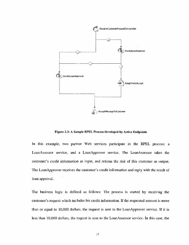
Let us look at an example of BPEL process now. Figure 2.3 shows a loan approval
process which is a sample included in ActiveBPEL V3.1 [ActiveBPEL]. This process
receives a customer's loan request for a certain amount. It returns the result of whether
the loan is approved to the customer.
16
ReceiveCustomerRequestForLoanAmt
\ j f ; InvokeLoanApprover
\J~
- # ~
i InvokeLoanAssessor
4 p - " j AssignYestoAccept
«... AcceptMessageToCustomer
Figure 2.3: A Sample BPEL Process Developed by Active Endpoints
In this example, two partner Web services participate in the BPEL process: a
LoanAssessor service, and a LoanApprover service. The LoanAssessor takes the
customer's credit information as input, and returns the risk of this customer as output.
The LoanApprover receives the customer's credit information and reply with the result of
loan approval.
The business logic is defined as follows: The process is started by receiving the
customer's request which includes his credit information. If the requested amount is more
than or equal to 10,000 dollars, the request is sent to the LoanApprover service. If it is
less than 10,000 dollars, the request is sent to the LoanAssessor service. In this case, the

LoanAssessor evaluates the risk of this customer and return the result to the BPEL
process. If the risk is low, the loan is approved and the final result is sent back to the
customer. Otherwise, the request is sent further to the LoanApprover. The result of the
LoanApprover is considered as the final result which is then replied to the customer.
Figure 2.4 gives a snippet of the BPEL definition of this process.
<bpel:invoke inputVariable="request" name= outputVariable="risk"partnerLink="assessor'
<bpel:targets>
"lnvokeLoanAssessor"operation="check" portType="lns:riskAssessmentPT">
<bpel:target linkName="receive-to-assess"/> </bpel:targets> <bpel:sources>
<bpel:source linkName="assess-to-approve"> <bpel:transitionCondition>$risk.level!
</bpel:source> = 'low'</bpel:transitionCondition>
<bpel:source linkName="assess-to-setMessage"> <bpel:transitionCondition>$risk. level =
</bpel:source> </bpel:sources>
</bpel:invoke>
= 'low'</bpel :transitionCondition>
Figure 2.4: Invoking the LoanAssesor Service in the Sample BPEL Process
2.2 QoS for Web Services
The need for QoS support for Web services is driven by two demands [Tian 2004]: From
the service requestor's perspective, they expect to experience good service performance,
such as fast response time, low cost, etc. A service with poor QoS is always unacceptable
even if it satisfies user's functional requirement. From the service provider's perspective,
offering QoS-aware Web services is able to attract more customers and therefore gaining
more profit. It is an important differentiator for providing a better service compared to the
competitors. For example, they can provide the same service in different quality levels to
18

meet different level of demands from customers. For services which are demanding on
some QoS dimensions, QoS guarantees can be offered to the customers. For instance, IP
phone service requires the latency to be less than a certain level. To provide good QoS,
service provides normally need to find an optimal relation between user satisfaction and
resource utilization.
Many researchers tend to believe that the main issue of Web service QoS at this moment
is the QoS specification and management. QoS specification is the issue of defining the
QoS parameters for Web services, such as response time, cost, etc. QoS management is a
generic term which consists of different management functions such as QoS monitoring,
adaptation, etc.
2.2.1 QoS Specifications
QoS can be measured from different dimensions. A QoS parameter is a property of the
service in a given dimension which is observed by the Web service users [Menasce 2002].
Defining the QoS parameters is fundamental for designing QoS-aware Web services. It
allows the user to specify their QoS requirement, and evaluate the service's QoS
performance. This section describes a number of important QoS parameters of Web
services.
1. Response Time: It is the time a Web service takes to react to a given request. From
the user's perspective, response time can be measured from the moment when the
service request is sent until the moment when the response is received. Normally,
faster response time is considered as better.
19
2. Availability: It is the proportion of time that a Web service in usable state.
Availability is usually measured for a random observation period. It is often
calculated as the ratio of the up time of a service to the total observation period.
Higher availability indicates higher degree of operability of a service which is usually
considered as better.
3. Throughput: Throughput is the average rate of service requests that are successfully
handled. Due to the limitation on resources, higher throughput always causes longer
response time [Kalepu 2003]. It is the service provider's task to balance between
these two QoS dimensions.
4. Reliability: Reliability is the probability that a Web service handles its requests as
required within a maximum period of time [Kalepu 2003].
5. Security: Security is to measure the degree of safety that a Web service can provide.
It could contain many safety-related properties, such as authentication mechanisms,
confidentiality, data integrity, protection from vicious attacks, etc. [Menasce 2002].
6. Cost: It is the price that a user needs to pay for using a Web service. Normally, users
expect lower cost. However, providing high quality of services always requires higher
cost from service providers. A good provider should try to offer their services with
low cost without sacrificing too much on other QoS dimensions.
2.2.2 Managing QoS for Web Services
QoS-enabled Web Services provisioning is achieved through a number of phases, each of
which is an important function of QoS management [Serhani 2004]:
1. QoS specification: QoS specification defines dimensions of quality that the users are
20

interested for a certain Web service. It is the foundation of QoS management system.
Normally, the user can pay attention to multiple QoS parameters at the same time.
Modeling each of them and finding out their relationship should be done prior to
managing the QoS for a service. The user can specify an overall QoS requirement
before invoking the service. The QoS management system should be able to break
down this requirement for each individual QoS parameters.
2. QoS measurement: QoS measurement defines algorithms and procedures to measure
a QoS parameter at run-time. Choosing a method to measure a QoS parameter
depends on its characteristics. It is an important step to be executed when verifying
or monitoring the QoS.
3. QoS selection: The service requestor should be able to select the service from
different candidates based on QoS requirement. In this case, the user's requirement
needs to be mapped to service provider's QoS model. Then the selection is often
modeled as a multi-criteria decision task [Serhani 2004]. For a composite Web
service, QoS selection can be also referred to the task that planning a service
composition for a certain QoS goal.
4. QoS negotiation: It is the phase when the service requestor and the service provider
try to reach a QoS agreement. It could happen before the requestor bind to the service
or after the agreement is violated during the execution. It is a challenge for both
parties to be able to negotiate without human's intervention. Normally, the
negotiation is guided by pre-defined policies.
5. QoS monitoring: The run-time QoS should be monitored regularly. The service
provider need to keep track of the actual QoS in order to decide whether the QoS
21
adaptation is required, and record the overall QoS performance after the execution is
done. For each individual QoS parameter, appropriate method, frequency, and
locations should be chosen for monitoring.
6. QoS adaptation: QoS adaptation is to maintain the run-time QoS as guaranteed in
the agreement. Normally it involves the action to improve a degraded QoS. In some
cases, the service provider might want to decrease the QoS in order to free some
resources. QoS adaptation is initiated by comparing the actual QoS with a threshold.
It will be further discussed later in this chapter.
2.2.3 QoS of Composite Web Services
The QoS of a composite Web service can be modeled as an aggregation of QoS of each
individual partner services [Menasce 2004]. Understanding the relationship between the
global QoS and QoS of participating services can help to achieve higher degree of
flexibility when managing the QoS for composite services. For example, the QoS of
composition might be able to be altered by changing the composition logic. In order to
study this relationship, we first need to understand service composition patterns.
[Jaeger 2004] introduces seven patterns for Web service composition based on the
workflow patterns in the workflow management. Each of these patterns represents a basic
structural element of composition, such as a sequence, a loop, or a parallel execution. The
logic of a composition can therefore be modeled as a single or a combination of multiple
patterns. Figure 2.3 is taken from [Jaeger 2004] to illustrate these seven patterns.
22

Figure 2.5: Web Service Composition Patterns (taken from [Jaeger 2004])
CP1 is a simple sequential pattern. CP2 is a loop pattern where the service(s) execution is
repeated for certain times. CP3 to CP7 are five parallel patterns. CP3 is XOR split
followed by a XOR join. CP4 is AND split followed by an AND join. CP5 is AND split
followed by an m-out-of-n join. CP6 is OR split followed by OR join, while CP7 is OR
split followed by an m-out-of-n join. Understanding composition patterns can help us
abstract the composition logic, especially when using workflow-based language such as
BPEL to define the composition.
Since a composition can always be modeled by these patterns, studying the aggregation
of QoS of for each pattern allow us to model the QoS of the composition. A number of
works [Jaeger 2004] [Cardoso 2002] [Menasce 2004] [Yu 2005] have been done to
23

model the aggregation QoS for different QoS parameters, such as response time,
availability, cost, etc. based on composition patterns.
2.3 QoS Adaptation
In a service-oriented environment, a QoS-adaptive service is one which is able to adapt
itself to the change in QoS. The term QoS-adaptive should not be confused with QoS-
aware. A QoS-aware service is one that can provide different levels of QoS to cope with
the change in the service execution environment. However, QoS-adaptive means
maintaining the initial QoS agreement if possible. When the agreement has been violated
or is to be violated, QoS adaptation is triggered. There are a few crucial aspects required
to be studied when designing an adaptation scheme:
1. Who should initiate the QoS adaptation? In most cases, QoS adaptation is triggered
by the service provider who is responsible for maintaining the service agreement.
However, the client can trigger the adaptation as well under certain business
requirements.
2. What is the level of automation of QoS adaptation? Ideally, the adaptation can be
triggered and maintained without human's intervention. However, it is a difficult goal
to achieve when dealing with highly flexible and autonomous Web services. That is
why a lot of existing adaptation schemes still require partially or fully attention from
human.
3. Which QoS parameters are considered for adaptation? When multiple QoS
parameters are specified for a service, either part of them or all of them can be
specified as the targets of adaptation. In this case, multiple QoS parameters construct
24

a multi-dimension space which represents the scope of overall QoS. This space can be
divides as two different areas: accepted QoS, and un-accepted QoS. The goal of
adaptation is to try to keep the overall QoS in the area of accepted QoS.
4. What are the conditions to trigger the adaptation? The conditions are normally
boundary values of QoS. It could be thresholds of minimum values or maximum
values. Again for multiple QoS parameters, these values that represent the overall
QoS should be mapped to each individual QoS dimension.
5. When should the adaptation be triggered? Obviously, if the overall QoS degrades
below the threshold, the adaptation should be triggered immediately. However, a pro
active scheme can be implemented so that the adaptation can be triggered in advance
to prevent the QoS become un-acceptable. In this case, the threshold is usually still
acceptable QoS value. Note that in some cases the QoS adaptation needs to be
triggered as well when the QoS "outperforms". In this thesis, we call the QoS is
degraded either it is becoming too bad or too good.
6. What is the QoS goal to achieve for a given adaptation? A goal should be set as a
condition to terminate the adaptation in order to minimize the waste of resources.
Theoretically, the adaptation should not bring the QoS beyond this goal.
7. What method is used to achieve the adaptation goal? Any mechanism that can alter
the QoS can be chosen for adaptation. For example, load balancing can be used at a
server to improve the throughput of a video playback service.
25
2.4 Summary
In this chapter, we introduced the necessary background knowledge for our research. We
explained the concept of Web services, the Web service architecture, and the main
technologies of Web services. We discussed the Web service composition and the
existing composition languages. We also looked into BPEL in detail.
Next, we studied the QoS issue of Web services. We discussed a few of most important
QoS parameters of Web services. Then, we discussed the QoS management for Web
services, and the involved activities such as QoS monitoring, adaptation, etc. As a special
case of Web service, QoS for composite Web services was studied at the end of this
section. We studied different composition patterns and their aggregation QoS.
In the last section, we discussed QoS adaptation by breaking it down to a number of sub-
tasks. In the next chapter, the related work of QoS adaptation for Web services will be
reviewed.
26

Chapter 3
State-of-the-Art in QoS Adaptation for Web Services
A lot of work has been done for QoS adaptation in networking. Several approaches have
been proposed for adapting QoS at network or middleware layers [Nahrstedt 2001].
Existing solutions include task scheduling, network flow control, resource management,
etc. Resource management consists of methods, for instance, bandwidth allocation on
Web servers, power management, etc. There are also other approaches that focus on QoS
adaptation on certain application domains [Nahrstedt 2001]. For example, adaptive media
coding and compression schemes can be used to create QoS-adaptive video applications.
Supporting QoS adaptation at middleware layer has become a hot topic in recent years. In
such cases, managing QoS requirement and adaptation polices can be easily separated
from applications' functionality implementation [Mujumdar 2005].
Supporting QoS adaptation for Web services is still immature as Web service is a
relatively new area. In this chapter, we discuss the related work in the area of Web
services first. Given the similarity between Web service composition and traditional
workflow management, we discuss how the problem is proposed to be solved for
workflow before we move on to Web service composition. In the third section, we review
four approaches proposed for composite Web services. Finally, we look into an important
work which is a broker-based solution for QoS management for Web services.
3.1 QoS-adaptive Web services
There are three types of techniques to support QoS adaptation for Web services in the
literature: Web service replication, Web service relocation, and dynamic Web service
invocation. All these approaches are generic solutions for Web services. For example,
they treat different types of Web services as the same, either is a composite one or a basic
one.
3.1.1 Web Service Replication
The basic idea of Web service replication is generating a number of replicas for a given
Web service so that the service requestor can choose different replicas to bind according
to the execution environment change. Existing approaches include [Keidl 2003] [Silva
2004] [Zegura 2000].
Service Requestor
Figure 3.1: Web Service Replication Using a Gateway
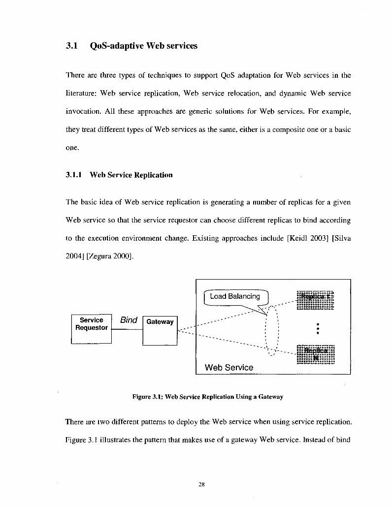
There are two different patterns to deploy the Web service when using service replication.
Figure 3.1 illustrates the pattern that makes use of a gateway Web service. Instead of bind
28
Bind Gateway
Load Balancing
Web Service
I 1 Replica 1 j
•
"V->'-.__ ; Replica ! ": N j

to the service directly, the service requestor binds to the gateway. The gateway is
responsible for dispatching the requests to different replicas.
Client Application
Service Selector
Service Requestor
Bind
Web Service
Replica 1
Replica N
Figure 3.2: Web Service Replication without Using a Gateway
Another deployment pattern is shown in Figure 3.2. Instead of using a gateway service to
select the replicas, a service selector is implemented at the service invocation layer of the
client software. It decides which replica to bind based on different policies and directly
binds to it. [Silva 2004] is an example that utilizes this pattern.
At the execution time, the service requestor can choose more than one replica to bind at
the same time. In this case, load balancing are normally required to distribute the traffic
to multiple replicas.
Replicas can be either offered by the service provider or found through UDDI. If
provided by the service provider, replicas are just service instances which are duplicated
from the original service and distributed to different hosts. Replicas can also be found
through UDDI for a given tModel. At run time, the service user can query a registry to
find out all the service instances (replicas) against a certain tModel.
29

The selection of replicas is another important issue of service replication. It is often
modeled as a selecting the best set of replicas for binding. If QoS of a replica degrades, it
is de-selected and a new set of replicas is re-selected.
Most of the existing approaches of service replication focus on developing algorithms for
replica selection, replica load-balancing mechanisms, etc. They are normally motivated
by improving the fault-tolerant ability of Web services. The adaptation is triggered by
service faults. However, we believe that the adaptation should happen not only in the case
of invocation failure, but also when the QoS will be potentially violated.
3.1.2 Web Service Relocation
Web service relocation is a method to transport a service instance from one host to
another one (location) at run time without the service requestor's awareness. Similar to
the service replication, the purpose of this technique normally is to improve the ability of
fault tolerance of the Web services. The service is relocated as soon as the current host is
detected in fault status which is illustrated by Figure 3.3.
Service Requestor
Bind Proxy
„ - -
' • " - - - . _
Web Service
\ Inst i
^
ar
V
,ce A ; Host 1
7
^ Instance * \ H o s t 2
Figure 3.3: Web Service Relocation
30

Fluid [Pratistha 2004] is a framework supporting Web service relocation. It allows Web
services to be nomadic so that they can transport to different destinations for adapting to
the changes in the surrounding environment. It is implemented by using mobile agent
technology. A proxy is built between the service provider and requestor. The requestor
can retrieve the location information from the proxy. [Pratistha 2004] points out the main
requirements of service relocation: reactivity, transportability, and adaptability.
1. Reactivity: is the ability of a Web service to trigger the relocation automatically
when sensing the need from surrounding changes.
2. Transportability: is the ability that allows a Web service to be relocated to a different
host.
3. Adaptability: allows a service to detect its context such as available resources of the
destination host, and adapt itself by reconfigure its structure to this context.
Both Web service relocation and replication alter the QoS by redeploy different resources
of the service provider for the running services. Some future improvements that
researchers are currently working on include improving the performance, scalability, and
extending to different type of Web services.
3.1.3 Dynamic Web Service Invocation
Based on the existing Web service standards, the selection of services can not be changed
once they are invoked at runtime. Improving QoS by dynamically choosing different
Web services to execute is the goal of this method. It is illustrated in Figure 3.4.

In service relocation or replication, the requestor always binds to the same service. These
techniques improve the QoS by changing the internal implementation of the service.
However, the method of dynamic service invocation moves the binding from one service
to another one. Therefore an important requirement of this method is that the new service
should have the same functional signature as the original one.
UDDI
! Web service A : -• i
' i
Swappable
- ~ " i
Web service B ! i i
Figure 3.4: Dynamic Web Service Invocation
[Yu 2004] proposes an architecture which extends Web service architecture to support
dynamic service invocation. They introduce a proxy between the service requestor and
the Web services. The proxy has a few functionalities: it monitors the status of the current
running service. When the status changes, for example, the current service is temporary
unavailable, the proxy retrieves a list of candidate services with the same function from
UDDI. A new service is then chosen from them and the proxy starts to dispatch the traffic
to it.
QoS adaptation can be achieved by dynamically binding to a new service with better QoS
if the current one can not provide an acceptable QoS. One of the main challenges of this
32
Service Requestor
DlflU
approach is the performance issue. The migration from one service to another should be
fast and reliable. In addition, the service execution can not be stopped during the change.
3.2 QoS-Adaptive Workflows
Since composing Web services is similar to designing a workflow [Aalst 2003], we
discuss some existing approaches to support QoS adaptation for workflow in this section.
In Workflow management, flexibility is a workflow's ability to modify its execution in
order to meet certain goals. If maintaining QoS is the goal, being flexible can be a way to
make the workflow QoS adaptable. In order to understand flexibility, a few concepts
need to be explained first. The business process of a workflow is modeled by its
type/schema [Petra 1999]. It defines the workflow by using workflow specification
language at design phase. At the execution phase, workflow instances are instantiated
from the workflow type.
A summary of the existing strategies for supporting flexible workflow is given in [Petra
1999]. They summarize two ways to achieve flexibility: by selection, or by adaptation:
1. Flexibility by selection: A number of alternate execution paths are defined in the
workflow type. At runtime, the execution path can be altered to one of these pre
defined alternatives. This strategy is called flexibility by selection. It can be further
divided into two methods:
a) Advance Modeling: At design time, every concrete alternate execution path is
defined.

b) Late Modeling: At design time, only abstract "black boxes" are defined for
the alternate execution paths. The concrete paths are defined at runtime.
2. Flexibility by adaption: Instead of defined at design phase, alternate execution paths
are generated on the fly at runtime and inserted into type definition or part of the
instances. Flexibility by adaption contains two methods as well:
a) Type adaption: The change does not affect running instances. Only the type
definition is modified. Therefore, the future instances will use the new workflow
definition.
b) Instance adaption: Opposite to type adaption, instance adaption changes the
running instances immediately. This change is only applied to individual
instance.
We need to point out that type adaption and instance adaption are not black or white.
Some recent researches combine them together to achieve better performance. In these
works, instance changes are monitored at run-time. Those appeared with high frequency
are collected and a type level change is made to reflect them.
If we compare these two strategies, flexibility by selection can be considered as
"anticipated" since the freedom offered to the execution is pre-defined at design time.
However, flexibility by adaption gives unanticipated freedom to the execution which only
response to the runtime variation. Although flexibility by adaption is more flexible, it is
expected to have worse performance due to the overhead introduced at run-time.
As we mentioned at the beginning of this section, flexibility can be used to develop QoS-
adaptable workflows. [Klingemann 2000] proposed a framework to achieve this. At
34

design time, alternate execution paths are inserted into the workflow schema definition.
On the other hand, the QoS goal is specified along with other functional specifications of
the workflow. At runtime, the possibility of successful fulfilling the QoS goal for each
possible execution paths is calculated based on the runtime monitored QoS. The most
optimized one is automatically chosen to meet the goal.
Although this approach is more focused on the QoS specification and the optimization
algorithm of path selection, the idea of improving QoS by changing the execution path at
run-time inspires us to solve the problem in the domain of Web service composition.
3.3 QoS Adaptation for Composite Web services
In this section, we review the state-of-the-art of supporting QoS adaptive composite Web
services. Since it is an evolving area, there are not many approaches that have been
proposed. Plus, none of them provide a comprehensive solution. Based on the strategy
used for QoS adaptation, we divide the existing works into 4 groups: 1) dynamic partner
Web services re-selection, 2) dynamic modification of composition schema, 3) automated
planning, and 4) AOP (Aspect-Oriented Programming) method. These 4 types of
approaches will be studied in this section.
3.3.1 Dynamic Partner Web Services Re-selection
Partner Web services are the basic units that form the composition. Based on the current
standards, the composition schema is developed at the design phase. During this stage,
which partner Web service should be selected for each task has decided. Current way of
composition does not offer any flexibility to change a partner Web service at run-time.
35
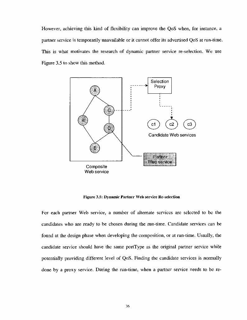
However, achieving this kind of flexibility can improve the QoS when, for instance, a
partner service is temporarily unavailable or it cannot offer its advertised QoS at run-time.
This is what motivates the research of dynamic partner service re-selection. We use
Figure 3.5 to show this method.
Composite Web service
Selection Proxy
d ) ( c2 ) ( c 3
Candidate Web services
Partner Web service
Figure 3.5: Dynamic Partner Web service Re-selection
For each partner Web service, a number of alternate services are selected to be the
candidates who are ready to be chosen during the run-time. Candidate services can be
found at the design phase when developing the composition, or at run-time. Usually, the
candidate service should have the same portType as the original partner service while
potentially providing different level of QoS. Finding the candidate services is normally
done by a proxy service. During the run-time, when a partner service needs to be re-
36

selected, the best candidate service is found and swapped with the current one. This task
can be also fulfilled by the proxy service.
[Karastoyanova 2004] proposes a mechanism called "find and bind" to support partner
service re-selection. They introduce a new activity find_bind for BPEL. Before the
invocation of each partner service, a find_bind is executed. Within this activity, the
UDDI registry is queried and a list of candidate services is retrieved. Then based on
certain policies, the best candidate is chosen and the subsequent invocation activity will
bind to it. This approach can provide an optimized service selection for every task.
However, the overhead introduced by find_bind is not negligible.
Another approach is proposed in [Canfora 2005]. Unlike the previous work, this approach
will not trigger the re-selection unless the overall QoS becomes un-acceptable. When the
re-selection is triggered, the execution stops. Which part of the composition has not been
executed is determined. Then the best candidate service is chosen for each remaining
partner service to maximize the overall QoS. After the re-binding is done, the service
execution is restored. This approach is able to provide good flexibility and the overall
QoS goal is taken into account. However, stopping the execution for the re-selection is
not acceptable in many cases.
[Patel 2003] proposes an architecture called WebQ. Instead of assigning a single partner
service to a task, a set of candidate services is assigned. Load balancing is used to
distribute traffic to different candidates. When a candidate service is detected providing
poor QoS, it will be de-selected and another set of candidates will be chosen to provide
best possible QoS. This work is focused on designing the selection algorithm. It does not
provide enough detail for the adaptation procedure.
A middleware approach is introduced in [Zeng 2004]. Similar to [Canfora2005], they re-
plan the selection of all the partner services which are about to be executed during the
run-time under the consideration of overall QoS. However, they also focus only on
selection algorithm.
The last work we would like to discuss is TRAP/BPEL which is proposed in [Onyeka
2007]. It is a framework which utilizes the transparent shaping programming model to
provide self-healing and self-optimization to BPEL process. They are more interested in
the programming detail of proxy implementation for service re-selection.
3.3.2 Dynamic Modification of Composition Schema
Although changing individual partner services provides flexibility for QoS adaptation,
sometimes we need to change the composition logic to gain bigger impact on the overall
QoS.
38

Composite Web service
Figure 3.6: Dynamic Modification of Composition Schema at Run-time
The modification of the composition schema can happen at any phase. If it happens at
non-execution phase, all the new instances will use the modified schema. A modification
that happens at execution phase is shown in Figure 3.6. When the QoS is becoming
unacceptable, the modification is triggered. A more optimized schema is designed for the
rest of the composition which is normally the un-executed portion right after the current
execution point. The new schema which might contains new logic or partner Web
services will replace the old one.
[Karastoyanova 2004] introduces a new activity called <evaluate> for BPEL. This
activity is designed for 2 purposes: changing the portType of a partner Web service at
39

run-time, and changing the composition schema at run-time. In order to change the
schema dynamically, the basic idea is to use the <evaluate> activity to wrap the portion
of the schema that is supposed to change. Also, assign a template which is a piece of
reusable code to the substitution schema in the <evaluate> activity. At runtime, the user
has to provide concrete parameters for the template to form a new schema to replace the
wrapped portion of <evaluate> activity. The need of user intervention may interrupt the
service execution which is not expected by the user sometimes. Also their approach
requires extending the current BPEL standards.
[Yu 2005] also proposes an approach. In this work, the designer specifies alternate
execution paths that can replace part of or all the composition. A composition manager
then find out all the possible execution plans based on user's input prior to the execution.
At runtime, when a service encounters problems, the execution engine select the best
backup path from the stored execution plan and switch to it for the rest of the process.
Although this work enables the composite Web service to change its schema on the fly,
the change is triggered only by the error of a partner service.
3.3.3 Automated Planning
Automated planning is a branch of artificial intelligence. The main concern is about
generating action sequence to meet certain goals. Given its similarity with Web service
composition, some researchers have tried to solve the composition issue by using
automated planning tools.

An example is the approach that is proposed in [Vukovic 2004]. They use a planner tool
called SHOP2 to change the composition logic when the monitored context environment
changes. SHOP2 is a HTN (Hierarchical Task Network) based planner. Its main feature is
implementing an abstract task by decomposing it and forming an execution plan. The
context and composition goal are fed into SHOP2. It generates a SHOP2 plan which is
then transformed into a BPEL schema. The proposed architecture contains a monitor
which constantly monitors the context. When the context changes, a new SHOP2 plan
will be generated and transformed into another BPEL schema. Although their work is not
designed for adapting QoS change, the core concept of how to solve the adaptation issue
is similar.
Changing the composition logic through planner is an interesting idea. However, there
are still a lot of challenges to be overcome such as how to fully map the Web service
description to the domain of planning.
3.3.4 AOP Method
AOP is a programming paradigm which aims at separating crosscutting concerns with
other functionalities. There are three key concepts in the AOP model: join point, pointcut
and advice. They are the basic units to define an aspect.
1. Join points are points in the execution of a program. For example, join points in
object-oriented programs can include method calls, constructor calls, field read/write,
etc.

2. In order to modularize crosscutting concerns, pointcut is introduced as a set of related
join points.
3. An advice specifies certain codes that run at a join point. It can be executed before,
after, or around a join point. The advice specifies when and what behavior must be
executed at the selected join points.
Since an aspect can be virtually anything, a number of existing approaches [Charfi 2004]
[Courbis 2004] [Verheecke 2004] use AOP to develop QoS-adaptive composite Web
services. Generally, these approaches define new composition logic as aspects and insert
them into the composition definition. If the composition schema needs to be modified at
run-time for adapting QoS change, the execution engine can just activate / de-activate the
appropriate aspects. The advantage of AOP is that advices can be executed before, after
or around a given point. It is therefore possible to add, delete, or replace activities in a
composition dynamically.
Using AOP to enable the dynamic change of composition logic has become an active
topic although AOP itself is immature and lack of tool support. These approaches
normally require modification to the current composition execution engine.
3.4 A Broker-based Architecture of QoS Management for Web
Services
In this section we discuss an approach of Web service QoS management proposed by M.
A. Serhani et al. [Serhani 2005] [Serhani 2006]. The reason we discuss it in a separate

section is that their idea of using QoS broker to do the QoS monitoring and adaptation
has been adopted by our research. Their architecture is illustrated in Figure 3.7.
Find
UDDIe
Publish
Service Requestor
Bind
.̂ QoS negotiation
Service Provide
- v V.
'QoS monitoring and adaptation
Figure 3.7: Broker-based Architecture for QoS-enabled Web services
Different from the standard Web service architecture, they introduce a QoS broker and
replace the traditional UDDI registry with a QoS-enabled registry called UDDIe [Ali
2003]. UDDIe allows service providers to publish their services with non-functional
specifications. It enables that a service is selected based on QoS constraints. The key
component is their architecture is the QoS broker. The broker is responsible for QoS
provisioning and management for Web services. It is a third-party Web service that can
be found through UDDI.
When a service provider publishes its Web service to UDDIe, it needs to receive a
certification from the QoS broker to prove the authenticity of the service's claimed QoS.
If a service requestor look up a service through UDDIe, it can use the result of the
certification to ensure the trustworthy of the service's QoS. When the requestor chooses
43

the service, the QoS broker initiates a QoS negotiation between the requestor and the
provider. Once both of them reach an agreement of the QoS level, the negotiation is done
and the agreement is stored into the broker's database. The requestor can then bind to the
service. During the execution, the broker is responsible for monitoring the run-time QoS.
If the QoS violates the agreement, a QoS adaptation is initiated by the broker until the
QoS becomes acceptable again. If the adaptation fails, a re-negotiation will be triggered
so that a new agreement can be reached.
This architecture is reported in [Serhani 2005] which inspires us to use a similar broker in
our architecture to solve QoS issues. Their work has focused on basic Web services, i.e.
Web services which do not result from a composition. We adapt the concept of QoS
broker and propose a new design to support composite Web services. Another
architecture, CompQoS, introduced in [Serhani 2006] supports composite Web services.
However, it is more focused on QoS management and monitoring, while we focus on
QoS adaptation.
3.5 Summary
In this chapter we reviewed the state-of-the-art of QoS adaptation for Web services. We
first gave a brief review of the research works on QoS adaptation. Then we studied the
approaches for supporting QoS-adaptive Web services. Three different types of solutions
were discussed, which include Web service replication, Web service relocation, and
dynamic Web service invocation. These solutions are generic for Web services. They do
not address the specific requirements of composite Web services.

Since our research focus on composite services, the related works were studied in the
next section. We summarized these approaches into 4 different methods: dynamic partner
Web services re-selection, dynamic modification of composition schema, automated
planning, and AOP method. For each type of method, its advantages and disadvantages
were studied.
The last section discussed a broker-based architecture for QoS management. This work
introduced an idea of solving QoS for Web services by using a third party broker. The
broker allows QoS negotiation, monitoring and adaptation to be integrated into the Web
service architecture. Our approach adopts this idea to solve the issue for composite Web
services.
We mentioned the requirements of supporting QoS adaptation for composite Web
services in Chapter 1. Through reviewing the state-of-the-art, we found that none of the
related work is able to meet all these requirements. From the next chapter, we will
introduce our proposed approach and explain how it solves these requirements.
45

Chapter 4
An Architecture for QoS Adaptation for Composite Web
Services
Since BPEL is considered as the de-facto standard of composition languages, we focus on
the Web service composition that is defined by BPEL in our work. The architecture we
propose enables automatic QoS monitoring and adaptation by dynamically changing the
execution paths of composed Web service when needed. In order to integrate the
definition of alternate execution paths into BPEL, we propose a new construct called
flexPath for BPEL which will be discussed in the first section. In the second section, we
will introduce the overall architecture and its major components. A typical procedure of
how QoS monitoring and adaptation works based on our architecture will be shown in the
third section.
4.1 flexPath: An Extension for BPEL
Current BPEL standard only supports one execution path. Once the BPEL process is
defined at the design phase, there is only one possible path for the process to be executed.
In order to provide flexibility into the process execution, we introduce the concept of
alternate execution path into process definition which is shown in Figure 4.1.
As we can see in Figure 4.1, the original execution path is a sequential execution of
activity W, X, Y, and Z. Then we add one alternate path for activity Y. It is a sequential
46

execution of activity A and B. In this example, the process now contains 2 possible
execution paths: WXYZ, or WXABZ. The changeable portion is Y/AB which is wrapped
by a new construct called flexPath. Therefore, a flexPath defines a segment of process
where multiple execution paths are defined. Among these paths, one of them is assigned
as the default path. The other paths are all backups which can be switched to at run-time.
original execution path alternate execution path
Figure 4.1: Defining Alternate Execution Path in BPEL
A question might be brought up at this point: current BPEL standard defines construct
such as <switch> to allow the definition of possible multiple branches that the process
make take. Is it doing the same job as flexPath? Similar question has been answered in
the domain of traditional workflow management. Conceptually, <switch> in BPEL
language represents an or-split/join structure. From the programming perspective,
flexPath is similar to an or-split/join structure. However, [Klingemann 2000] points out
47

that from the workflow perspective, they are different, only the chosen path in an or-
split/join is considered as a "correct" path and the decision is made based on the
evaluation of a predicate and cannot be influenced, while the flexPath has the opposite
characteristics.
In the rest of the thesis, the term flexPath refers to the segment in the BPEL process that
is wrapped in a flexPath structure.
4.2 The Overall Architecture for QoS-adaptive Composite Web
Services
Our proposed architecture is based on the usage of a third party QoS broker. This idea is
brought from the work of Serhani et al. as we mentioned in Chapter 3. The QoS broker is
responsible for managing the QoS and can be exposed as a Web service. In our
architecture, however, the broker is specifically designed to monitor the QoS of a
composed Web service and managing the QoS adaptation for it when needed. Figure 4.2
illustrates our proposed architecture.
48

Q o S Broker Web Service
Topology interpreter
QoS Monitor
QoS Adapter
>S§|is!W&S?
1 V
Service Requestor
s
,
-
Partner Web Services
': VVSiv;.
WS21
WS221
WS222
W S 3
1 flexPath
BPEL Compi ler
Figure 4.2: Overall Architecture for QoS-adaptive Composite Web Services
The architecture consists of five main components: Service requestor, BPEL process,
partner Web services, BPEL compiler, and QoS broker:
1. Service requestor is the customer that invokes the composite Web service.
2. BPEL process is the composed Web service published by the service provider.
3. Partner Web services are the basic units that form the composition of the BPEL Web
service. They can be published by the same service provider who publish the BPEL
process, or other service providers.
4. BPEL compiler is a tool for instrumenting the BPEL process. After a BPEL process is
designed, it needs to be instrumented to make it adaptation-enabled. Without the
instrumentation, the BPEL process will not be able to be managed by the QoS broker.
49
5. QoS broker is published as a Web service responsible for managing the QoS of BPEL
processes. It mainly interacts with the BPEL process during the run-time to monitor
its QoS and change its execution path when the QoS is too poor. It also interacts with
the service requestor and the partner Web services. As mentioned in [Serhani 2005],
each service needs to get a certification from the QoS broker to verify their claimed
QoS before they are published in UDDI. Therefore, for each partner Web service,
there should be at least 2 pieces of data stored in the broker's database: its claimed
QoS, and its actual QoS based on its past performance statistics. The broker also
needs to communicate with the service requestor for tasks like QoS negotiation
[Serhani 2005]. After a successful negotiation, the QoS agreement is stored in the
broker's database. It is a key reference for the broker to decide whether the adaptation
should be initiated at runtime. The main components of the QoS broker include
topology interpreter, QoS monitor, QoS adapter, and QoS database. They will be
explained in detail later.
Note that UDDI registry is not included in our architecture. It is because that we do not
need it to participate into the task of QoS monitoring and adaptation. It is preferable that
the service providers publish their composite Web services into a QoS-enabled registry
such as UDDIe. In that case, the broker can directly get the QoS information of each
service from the registry.
50

4.3 Procedure of QoS Adaptation Based on the Proposed
Architecture
We introduced the overall architecture and its main components in the previous section.
In this section, we describe how the BPEL service adapts to the QoS goal based on this
architecture. Figure 4.3 describes how the components interact with each other.
Service Requestor
QoS Broker BPEL Process I Partner Web Services
BPEL Compiler
1: Define the workflow with flexPath
2: Certify its claimed QoS
3: Response with the certification result
, 4: Request for instrumentation
5: Response with adaptation-ready version
6: Initate the QoS negotiation
with the service prqvider
6: Response of negotiation
11: Bind - ^ T n
* i 12: Initiate the workflow execution
13: Resquest for QoS management
14: QoS monitoring u > 15: Initiate the QoS adaptation
16: Nbtify with the result of execution
Figure 4.3: Component Interaction of Proposed Architecture
51

1. During the design phase, the BPEL process designer finds all the segments inside the
process that can be replaced by alternate execution paths. He defines a flexPath
wrapping each segment with all the possible alternate execution paths.
2. Before publishing at the UDDI registry, all the services including partner Web
services and the BPEL service itself need to get a certification from the QoS broker.
The QoS broker stores the QoS information of these services.
3. The BPEL process is then sent to the BPEL compiler for instrumentation with new
activities which interact with the broker. The service provider then use the
instrumented BPEL definition files which are considered as adaptation-enabled to
deploy on the server.
4. Before the service requestor binds to the BPEL Web service, the broker starts the
negotiation between them in terms of QoS. Once an agreement is reached, the QoS
contract is stored into the broker's database.
5. The service requestor binds to the BPEL service.
6. At the execution phase, an instance of the BPEL process is instantiated whenever a
request is received from the requestor.
7. As the BPEL process starts to execute, it sends the BPEL definition files to the
broker. The broker abstracts the topology from the definitions, and starts the adapter
and monitor to manage the QoS of the execution.
8. During the execution, the QoS monitor measures the QoS at certain places in the
process. As soon as the QoS is considered as unacceptable, the adapter will trigger
the adaptation. It finds out the next flexPath to be executed, and calculates the best
execution path among all the alternate paths. The result of path selection is sent to
52

the BPEL process. The BPEL process switches to the new path according to the
notification from the broker.
9. After a successful execution, the broker updates the historical QoS data of each
partner Web service by using its QoS results.
4.4 Summary
In this chapter, we discussed our proposed architecture. We introduced our extension to
BPEL which is a construct called flexPath to support alternate execution paths in the
BPEL definition. Our solution is changing the execution path of the BPEL process during
the run-time in order to adapt to QoS degradation.
The overall architecture was discussed in section 2. We use a QoS broker to monitor the
QoS and manage the adaptation for the BPEL process. The process is instrumented by a
BPEL compiler before deployment so that it is able to be managed by the broker. The
main components of the architecture and their roles were studied in this section. In the
next section, we studied the interaction among these components. From the next chapter,
we will discuss the design of each component in our architecture.
53

Chapter 5
BPEL Process Instrumentation
As we mentioned in the previous chapters, the BPEL process needs to be instrumented in
our architecture. We discuss the procedure of instrumentation in this section. Describing
a BPEL process usually contains a number of files. There should be at least a BPEL
definition file, a WSDL file, and a file to define the deployment details. In our
architecture, we design a BPEL compiler which takes these files as input and
automatically modifies them. The content added to these files is responsible for
communicating with the broker at run-time to fulfill the task of QoS monitoring and
adaptation. Mainly, there are three things that are inserted by the BPEL compiler:
partnerLinkType and partnerLink of the broker, probes, and PathSelectors. The design of
BPEL compiler will be discussed in the first section. The instrumentation of each type of
contents will be discussed in the second section.
5.1 Automatic Instrumentation Using JDOM
The architecture of the BPEL compiler is described in Figure 5.1. All the files that need
to be instrumented are written in XML. These XML files are first parsed by an XML
parser. Then we use JDOM [JDOM] to model it in JAVA. After the instrumentation is
done, new XML files are generated.
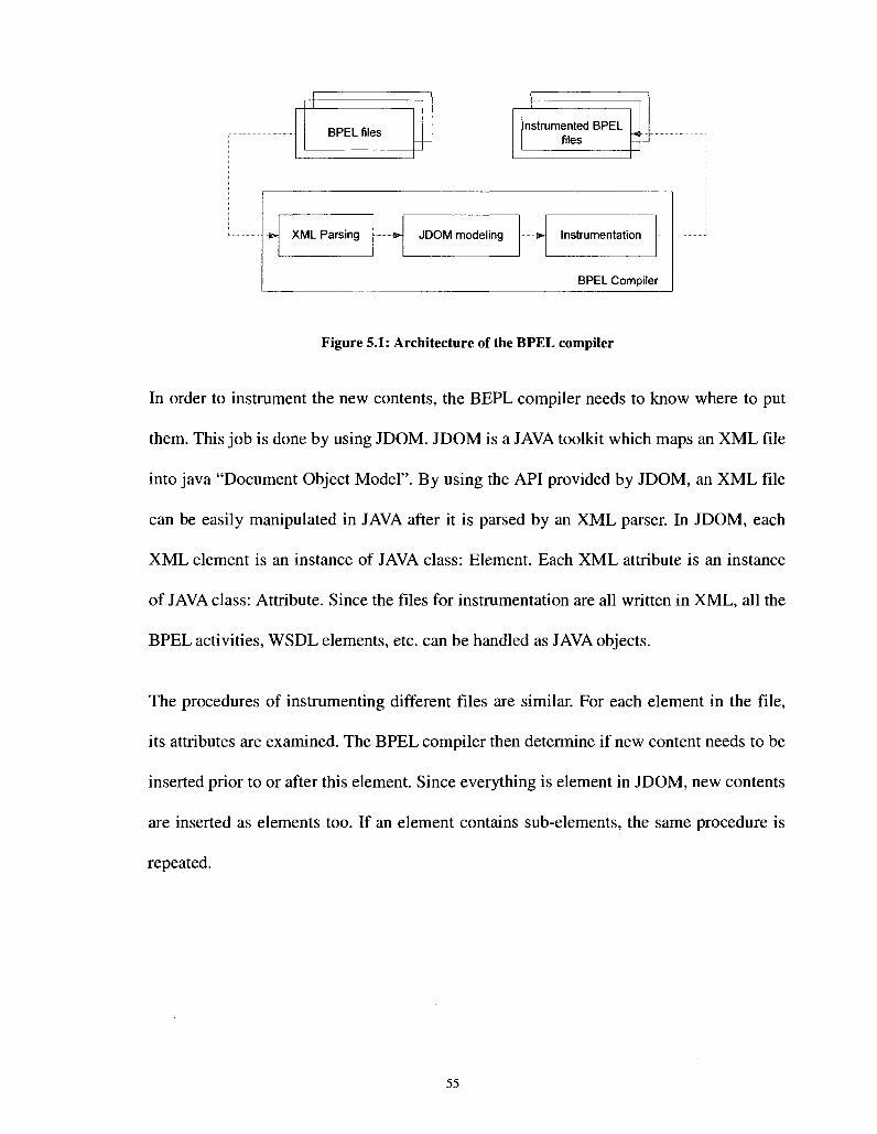
nstrumented BPEL
XML Parsing *- JDOM modeling »• Instrumentation
BPEL Compile r
Figure 5.1: Architecture of the BPEL compiler
In order to instrument the new contents, the BEPL compiler needs to know where to put
them. This job is done by using JDOM. JDOM is a JAVA toolkit which maps an XML file
into java "Document Object Model". By using the API provided by JDOM, an XML file
can be easily manipulated in JAVA after it is parsed by an XML parser. In JDOM, each
XML element is an instance of JAVA class: Element. Each XML attribute is an instance
of JAVA class: Attribute. Since the files for instrumentation are all written in XML, all the
BPEL activities, WSDL elements, etc. can be handled as JAVA objects.
The procedures of instrumenting different files are similar. For each element in the file,
its attributes are examined. The BPEL compiler then determine if new content needs to be
inserted prior to or after this element. Since everything is element in JDOM, new contents
are inserted as elements too. If an element contains sub-elements, the same procedure is
repeated.
55
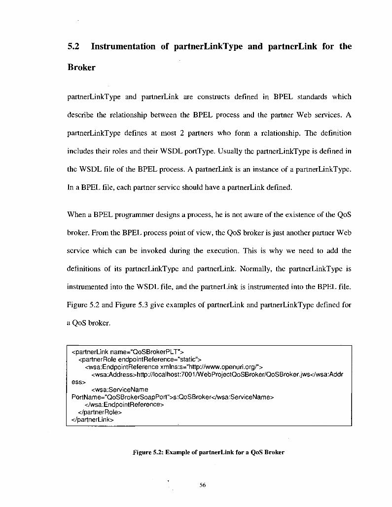
5.2 Instrumentation of partnerLinkType and partnerLink for the
Broker
partnerLinkType and partnerLink are constructs defined in BPEL standards which
describe the relationship between the BPEL process and the partner Web services. A
partnerLinkType defines at most 2 partners who form a relationship. The definition
includes their roles and their WSDL portType. Usually the partnerLinkType is defined in
the WSDL file of the BPEL process. A partnerLink is an instance of a partnerLinkType.
In a BPEL file, each partner service should have a partnerLink defined.
When a BPEL programmer designs a process, he is not aware of the existence of the QoS
broker. From the BPEL process point of view, the QoS broker is just another partner Web
service which can be invoked during the execution. This is why we need to add the
definitions of its partnerLinkType and partnerLink. Normally, the partnerLinkType is
instrumented into the WSDL file, and the partnerLink is instrumented into the BPEL file.
Figure 5.2 and Figure 5.3 give examples of partnerLink and partnerLinkType defined for
a QoS broker.
<partnerl_ink name="QoSBrokerPLT"> <partnerRoleendpointReference="static">
<wsa:EndpointReferencexmlns:s="http://www.openuri.org/"> <wsa:Address>http://localhost:7001/WebProjectQoSBroker/QoSBroker.jws</wsa:Addr
ess> <wsa:ServiceName
PortName="QoSBrokerSoapPort">s:QoSBroker</wsa:ServiceName> </wsa:EndpointReference>
</partnerRole> </partnerLink>
Figure 5.2: Example of partnerLink for a QoS Broker
56

<plnk:partnerLinkType name="QoSBrokerPLT"> <plnk:role name="QoSBrokerProvider">
<plnk:portType name="ns1 :QoSBroker" /> </plnk:role>
</plnk:partnerLinkType>
Figure 5.3: Example of partnerLinkType for a QoS Broker
5.3 Instrumentation of Probes
We define a probe as a group of activities with the main task to invoke QoS broker Web
service for the purpose of QoS monitoring. It is instrumented into the BPEL file. During
the run-time, the probes are the locations where the monitor measures the QoS. For
example, each time the execution of a partner service is completed, the QoS should be
measured. Therefore, at least one probe should be inserted prior to and after a partner
service invocation. We also wrap each flexPath with 2 probes so that its QoS can be
monitored as a whole. An example of instrumenting probes into a BPEL file is shown in
Figure 5.4.
57

Receive
Invoke WS2A
Invoke WS2B
( Reply ) Original BPEL
BPEL Compiler
probe
Invoke WS2A
Receive
Invoke WS1:
Invoke WS2B
Intrumented C Reply J BPEL
Figure 5.4: Example of Probe Instrumentation
Each probe is a sequence of BPEL activities. The brief design of a probe is shown in
Figure 5.5. Three actions are executed in a probe. At first, a unique probe ID is generated
and assigned to the probe. This ID is used by the QoS broker in order to identify the
probe. The probe then invokes the QoS broker Web service. As soon as the broker is
invoked, it measures the current QoS and decides if the adaptation should be triggered.
This decision is included in the response which is sent back to the probe. It will be used
to update a flag called isAdaptationRequired defined in the BPEL process. It is a variable
that is instrumented into the BPEL file. This flag indicate whether or not the adaptation
should be triggered. Whenever a flexPath is about to be executed, this flag is checked. If
it is TRUE, then the BPEL process knows that a better execution path needs to be
selected within this flexPath.
58

=:sequence>
Assign a probe ID
Invoke QoS monitor
Update isAdaptationRequired
Request to QoS broker
H|> s ® x
Response from QoS broker
Figure 5.5: Design of the Probe
Not all the probes are designed in the same way. For example, the first and the last one
have their own tasks. Except doing the aforementioned actions, the first probe in the
process needs to send the BPEL definition as a XML string to the broker. It is for the
broker to understand the schema of the composition at the beginning of the execution.
The last probe needs to collect some extra information such as the statistics of the
performance of the execution.
5.4 Instrumentation of pathSelector
We define a pathSelector as a group of activities that are responsible for selecting the
execution path of a flexPath. It is always inserted right before a flexPath. Figure 5.6
shows the result of instrumenting probes and pathSelectors into the previous example
which is described in Figure 5.4.
59

Receive
Invoke WS1
. ( Reply Intrumented V
BPEL
Invoke WS2A
- - J
Invoke WS2B
Figure 5.6: Instrumentation of Probes and pathSelectors
As same as the probe, a pathSelector is a sequence of BPEL activities. Its design is shown
in Figure 5.7. A unique pathSelector ID is generated and assigned for each pathSelector.
Then it checks the flag isAdaptationRequired. If it is FALSE, the pathSelector will do
nothing and the default execution path will be selected for the following flexPath. If the
flag is TRUE, it will ask the QoS broker which path to choose. Upon receiving the
request from the pathSelector, the broker determines the best execution path based on the
pathSelector's location and the current QoS.
60

<sequence>
Assign a pathSelector ID
Y ¥
Invoke QoS adapter
Update execution Path ID
isAdaptationRequired = FALSE
Request to QoS broker
Response from QoS broker
Figure 5.7: Design of the pathSelector
5.5 Summary
In this chapter, we explained the process of instrumentation which is accomplished by the
BPEL compiler. The design of the compiler was discussed in the first section. The
instrumentation is done by using JDOM toolkit. We then introduced the concept of probe
and pathSelector. They are activities inserted into BPEL file for communicating with QoS
monitor and adapter in the broker. We studied the design of them, and where they should
be instrumented. We also discussed the instrumentation of partnerLink and
partnerLinkType of the broker into BPEL and WSDL files.
61

Chapter 6
A QoS Broker for Automatic Monitoring and Adaptation
We introduced and discussed automatic instrumentation of BPEL processes in the
previous chapter. In this chapter, we will discuss the design of the QoS broker in detail.
As we mentioned in Chapter 4, the broker consists of 4 components: topology interpreter,
QoS monitor, QoS adapter, and QoS database. We will study the design of each
component in this chapter.
6.1 Topology Interpreter
While monitoring a running process, there are two important things that the broker needs
to know: 1) what is the schema of this running instance? 2) Where is the current
execution point, such as the location of the last probe and the next flexPath? This task is
done by the Topology Interpreter.
When the BPEL process starts its execution, the first probe will notify the broker with its
BPEL definition. Similar to the instrumentation process, the Topology Interpreter parses
this BPEL file by using JDOM. However, the JDOM representation is not able to provide
details such as the locations of probes, flexPaths, etc. We therefore designed a tree data
structure on top of the JDOM representation to represent the schema.
Before we explain the topology abstraction, we need to understand different patterns in
Web service composition. We have discussed the composition patterns in Chapter 2. In a
composed Web service, the relationship between basic partner Web services can be
sequential, parallel, conditional, or loop [Yu 2005]. [Cardoso 2002] shows that all these
patterns can be converted into the sequential one. Therefore, this thesis focuses on BPEL
processes containing only sequential composition.
Now let us continue the discussion of designing the data structure that models the BPEL
process. In this tree data structure, each node is called a section. Every section is a BPEL
activity. The root section represents the BPEL process itself. Not all the BPEL activities
are mapped to a section. For example, we ignore the <assign> activity since it is
unrelated to the execution path modeling. In our research, the only changeable units in an
execution path are invocations to partner Web services. Other activities are ignored
during the topology modeling.
There are three types of sections: Partner Web service invocation, sequence, and flexPath.
The section whose type is "partner Web service invocation" represents a <invoke> to a
single partner Web service. The section whose type is "sequence" represents a
<sequence> activity. For structured activities, since we only handle the sequential pattern
of the composition, the only structured activity we need to handle in the topology
interpreter is <sequence>. The section whose type is "flexPath" represents a <flexPath>
activity.
A section can contain sub-sections. Therefore each BPEL activity that is mapped to a
section may belong to other sections. If a section represents a basic BPEL activity such as
63
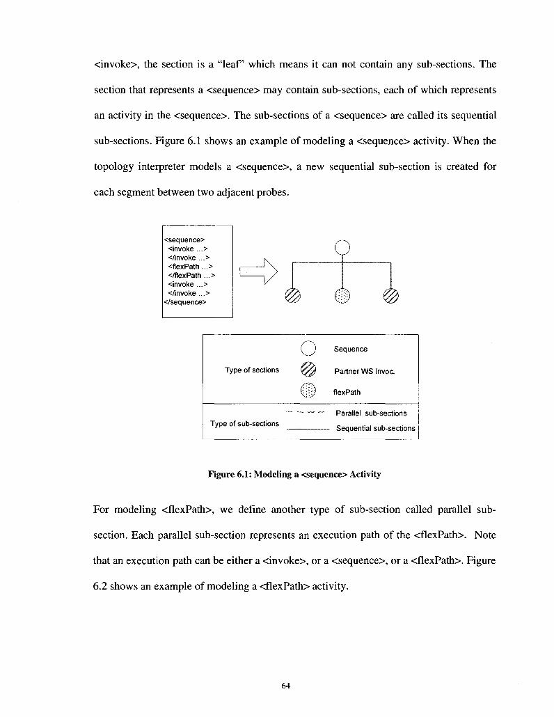
<invoke>, the section is a "leaf which means it can not contain any sub-sections. The
section that represents a <sequence> may contain sub-sections, each of which represents
an activity in the <sequence>. The sub-sections of a <sequence> are called its sequential
sub-sections. Figure 6.1 shows an example of modeling a <sequence> activity. When the
topology interpreter models a <sequence>, a new sequential sub-section is created for
each segment between two adjacent probes.
<sequence> <invoke ...> </invoke ...> <flexPath ...> </flexPath ...> <invoke ...> </invoke ...>
</sequence>
Type of sections
„
Type of sub-sections
o @
m
Sequence
Partner WS Invoc.
flexPath
Parallel sub-sections
- Sequential sub-sections
Figure 6.1: Modeling a <sequence> Activity
For modeling <flexPath>, we define another type of sub-section called parallel sub
section. Each parallel sub-section represents an execution path of the <flexPath>. Note
that an execution path can be either a <invoke>, or a <sequence>, or a <flexPath>. Figure
6.2 shows an example of modeling a <flexPath> activity.
64

<flexPath> <execution path ...> <invoke ...> </invoke ...> <invoke ...> </invoke ...>
</execution path ...> <execution path ...> <invoke ...> </invoke ...> <sequence ...> </sequence ...>
</execution path ...> </flexPath>
Type of sections
Type of sub-sections
o @
m
Sequence
Partner WS Invoc.
flexPath
Parallel sub-sections
Sequential sub-sections
Figure 6.2: Modeling a <flexPath>
To answer the second question, we establish ownerships between a probe and its
associated section. Also, the topology interpreter tracks the order of execution among
sections. Therefore as long as the broker knows the ID of a probe, it knows the execution
point of the BPEL process. Locating flexPath is handled in a similar way.
6.2 QoS Monitor
We monitor the QoS of a running process by using the QoS monitor in the broker. Each
time a probe is invoked, it will notify the QoS monitor to calculate the current QoS. The
scheme used by the calculation depends on the QoS parameters. In this thesis we study
one dimensional QoS only and we pick response time as our QoS parameter. The QoS
65

monitor calculates t„ - ti as the response time at probe n, where tj is the time when the
monitor gets the notification from probe i.
Note that the response time we measure at the broker is not the same as the response time
the user experiences. This is the limitation when using a 3rd party monitor to measure
QoS. However we also need to know that setting up a monitor at the client side is
generally unrealistic.
6.3 QoS Adaptor
The QoS Adapter plays a key role in the broker by executing two main tasks: for each
flexPath, it has to decide whether the adaptation needs to be triggered. If the adaptation is
necessary, it must find a better execution path in order to improve the degraded QoS.
In order to decide if adaptation is required, the adapter needs to answer a key question: is
the current QoS too low? If yes, the adaptation will then be triggered. Let us look at an
example: at flexPathm, the adapter retrieves the current response time Tm from the
monitor. If the QoS contract is Tc, then the condition to trigger the adaptation is P(Tm +
Tf > Tc) > x, where 0 < x < 100%. Here x is the probability threshold that is set by the
broker administrator. Tf is the future QoS which is predicted by the broker. This
prediction is based on the historical QoS data of each partner Web service. If the broker
has no QoS data record for a partner Web service, it will use its claimed QoS. Note that
how to predict Tf is another subject, which is out of the scope of this thesis.
After deciding the triggering of adaptation, the next step is to find the best alternate
execution path. Let us continue with the aforementioned example. We need to divide Tf
66

into two parts: Tf.fpath and Tf-resH where Tf.fpath is the predicted future response time of the
current flexPath, and Tf.rest is the predicted future response time of the rest of the process.
Assume there are N different execution paths in this flexPath, and the adapter measures
their predicted response time to be Tf.fpathi, ..., Tf.fpathN. Let Pn = P(Tm + Tf.fpathn + Tf.rest >
Tc), where n = 1 ... N. Then path k will be selected as the best path if Pk <= x, and Pk is
the greatest among all Pn which satisfies this condition. If there is more than one path
with the same predicted response time, we randomly chose one. If no alternate path is
able to meet the requirement, the path with the shortest predicted response time will be
selected. The whole procedure is illustrated in Figure 6.3.
Receive
tf-fPath1
BPEL Process
Reply J-
tm (executed)
tf-fPalh tf-fPathn
tf-rest
Figure 6.3: Determine the Probability of Violation of Response Time
67
Again, we only consider Response time in our research. When multiple QoS parameters
are involved, the best execution path should have the best overall QoS. A path with the
best QoS in one dimension is not necessary the overall best. For example, a faster
response time is normally associated with a higher price.
6.4 Summary
In this chapter, we studied the design of the QoS broker which has 4 major components:
topology interpreter, QoS monitor, QoS adapter, and QoS database. We first explained
how the topology interpreter extracts the schema of a BPEL process by modeling its
BPEL definition as a tree data structure. We explained how the topology interpreter tracks
the current execution point by using the tree data structure.
We then studied the QoS monitor and QoS adapter. In our research, they are designed to
handle one QoS parameter only: response time. QoS monitor measures the date and time
at every probe to calculate the latest response time. QoS adapter uses the current
measured response time, the predicted future response time of the un-executed segment
of the process, and the QoS contract to determine if the adaptation needs to be initiated. If
so, it also determines which execution path is the best on the next flexPath.
We pointed out that the algorithm used in the QoS broker depends highly on the QoS
parameters that need to be handled. On the next chapter, we will discuss the
implementation of the prototype tool and use a case to study our architecture.
68

Chapter 7
A Prototype Tool and Case Study
We implemented a prototype tool that includes a BPEL compiler and a QoS broker based
on our architecture. We also built a few example BPEL processes and a number of
dummy partner Web services to evaluate our proposed architecture. In this chapter we
discuss the implementation of the prototype tool. We then use an example to do a case
study, and analyze the result of the QoS adaptation.
7.1 Implementation of Prototype Tool
In our prototype tool, the BPEL compiler is written in Java. The broker and dummy Web
services are designed and deployed through BEA WebLogic 9.2 [WebLogic]. The BPEL
process is designed and deployed by using ActiveBPEL 3.1 [ActiveBPEL]. All the
components run on a stand-alone computer which has Intel Pentium 4 3.0GHz CPU, 1GB
RAM with Microsoft Windows XP SP2 as operating system.
When designing BPEL processes, we use <switch> activity to simulate flexPath given the
similarity between the <switch> activity and the flexPath construct. The <switch> will
choose the execution path based on the information retrieved from the corresponding
pathSelector.
69
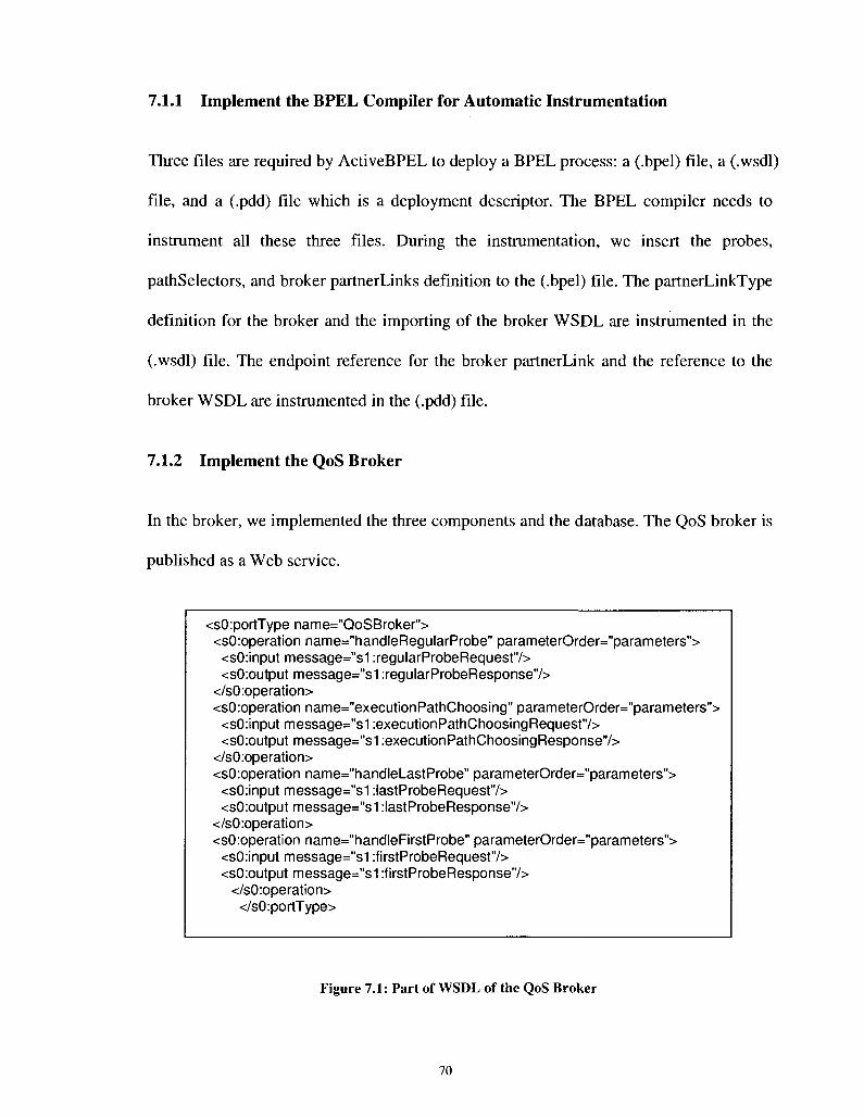
7.1.1 Implement the BPEL Compiler for Automatic Instrumentation
Three files are required by ActiveBPEL to deploy a BPEL process: a (.bpel) file, a (.wsdl)
file, and a (.pdd) file which is a deployment descriptor. The BPEL compiler needs to
instrument all these three files. During the instrumentation, we insert the probes,
pathSelectors, and broker partnerLinks definition to the (.bpel) file. The partnerLinkType
definition for the broker and the importing of the broker WSDL are instrumented in the
(.wsdl) file. The endpoint reference for the broker partnerLink and the reference to the
broker WSDL are instrumented in the (.pdd) file.
7.1.2 Implement the QoS Broker
In the broker, we implemented the three components and the database. The QoS broker is
published as a Web service.
<sO:portType name="QoSBroker"> <sO:operation name="handleRegularProbe" parameterOrder="parameters">
<sO:input message="s1 :regularProbeRequest"/> <sO:output message="s1 :regularProbeResponse"/>
</sO:operation> <sO:operation name="executionPathChoosing" parameterOrder="parameters">
<sO:input message="s1 :executionPathChoosingRequest"/> <sO:output message="s1 :executionPathChoosingResponse"/>
</sO:operation> <sO:operation name="handleLastProbe" parameterOrder="parameters">
<sO:input message="s1 :lastProbeRequest"/> <sO:output message="s1 :lastProbeResponse'7>
</sO:operation> <sO:operation name="handleFirstProbe" parameterOrder="parameters">
<sO:input message="s1 :firstProbeRequest"/> <sO:output message="s1 :firstProbeResponse"/>
</sO:operation> </sO:portType>
Figure 7.1: Part of WSDL of the QoS Broker
70

The portType of the QoS broker Web service is defined as in Figure 7.1. In this prototype
tool we define 4 operations for the QoS broker:
1. handleFirstProbe: this operation handles the invocation from the first probe of a
BPEL process.
a) Input message:
i. bpelDefinition (type = xs:string)
ii. probelD (type = xs:int)
b) Output message:
i. none
c) Description: The QoS broker does a few things in this operation. It asks the
topology interpreter to model the schema of the process by analyze the BPEL
definition which is included in the input message. It also initiates the QoS
monitor and adapter to start managing the running instance.
2. handleRegularProbe: this operation handles the invocation from a probe which is
neither the first nor the last one of a BPEL process.
a) Input message:
i. probelD (type = xs:int)
b) Output message:
i. currentResponseTimelnSec (type = xs:float)
ii. adaptationFlag (type = xs:boolean)
c) Description: In this operation, the QoS monitor measures the current QoS
(response time) and send it back through the output message. The QoS adapter
asks the topology interpreter for the current execution point by passing the probe
71

ID from the input message. After knowing which part of the process has been
executed and which has not, the adapter determines if the current QoS becomes
unacceptable by using the measured QoS from the monitor and the QoS contract
stored in the broker's database. If the answer is yes, the adaptation flag in the
output message will be set to TRUE. Otherwise it remains FALSE.
3. handleLastProbe: this operation handles the invocation from the last probe of a
BPEL process.
a) Input message:
i. probelD (type = xs:int)
b) Output message:
i. finalResponseTimelnSec (type = xs:float)
c) Description: Upon receiving the invocation from the last probe, the QoS monitor
and adapter are notified to stop managing the QoS for the running instance. The
final measured QoS (response time) is retrieved from the QoS monitor and sent
through the output message.
4. executionPathChoosing: this operation handles the invocation from a pathSelector
of a BPEL process.
a) Input message:
i. pathSelectorlD (type = xs:int)
b) Output message:
i. suggestedExecutionPath (type = xs:int)
c) Description: In this operation, the QoS adapter first uses the pathSelectorlD to
determine the current execution point through topology interpreter. It then
72
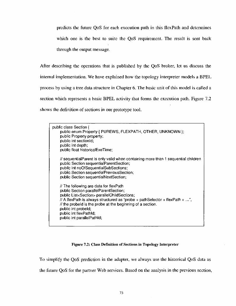
predicts the future QoS for each execution path in this flexPath and determines
which one is the best to suite the QoS requirement. The result is sent back
through the output message.
After describing the operations that is published by the QoS broker, let us discuss the
internal implementation. We have explained how the topology interpreter models a BPEL
process by using a tree data structure in Chapter 6. The basic unit of this model is called a
section which represents a basic BPEL activity that forms the execution path. Figure 7.2
shows the definition of sections in our prototype tool.
public class Section { public enum Property { PUREWS, FLEXPATH, OTHER, UNKNOWN }; public Property property; public int sectionld; public int depth; public float historicalExeTime;
// sequentialParent is only valid when containing more than 1 public Section sequential ParentSection; public int noOfSequentialSubSections; public Section sequential PreviousSection; public Section sequentialNextSection;
// The following are data for flexPath public Section parallelParentSection; public List<Section> parallelChildSections; // A flexPath is always structured as "probe + pathSelector + // the probeld is the probe at the beginning of a section. public int probeld; public int flexPathld; public int parallelPathld;
sequential children
flexPath + ...",
Figure 7.2: Class Definition of Sections in Topology Interpreter
To simplify the QoS prediction in the adapter, we always use the historical QoS data as
the future QoS for the partner Web services. Based on the analysis in the previous section,
73

we also simplify the condition for triggering the adaptation as: Tm + Tf_fpath + Tf_rest > Tc *
f, where f is a prediction factor with value from 0 to 100%. The reason of introducing this
factor is to compensate the system overhead. We will show the impact of the factor in the
next section. As for the QoS contract, we do not want to make it too tight or too loose
which is rare in reality. Thus, we choose the QoS contract to be equal to the overall
historical response time of the BPEL process.
7.2 A Case Study
Invoke: VVS21
I
Instrumented BPEL
Invoke WS231
Invoke WS22
(Si TiexPath 2
Invoke WS2321
Invoke WS 2322
Invoke WS 233
[ Q Reply ~)
m Q
probe
pathSelector
default execution path
Figure 7.3: The Instrumented Example BPEL Process
In order to evaluate out prototype tool, we design a BPEL process which invokes a
74
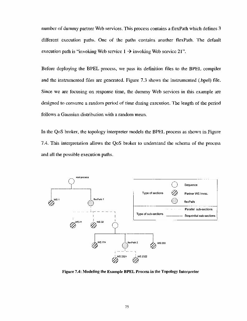
number of dummy partner Web services. This process contains a flexPath which defines 3
different execution paths. One of the paths contains another flexPath. The default
execution path is "invoking Web service 1 -> invoking Web service 21".
Before deploying the BPEL process, we pass its definition files to the BPEL compiler
and the instrumented files are generated. Figure 7.3 shows the instrumented (.bpel) file.
Since we are focusing on response time, the dummy Web services in this example are
designed to consume a random period of time during execution. The length of the period
follows a Gaussian distribution with a random mean.
In the QoS broker, the topology interpreter models the BPEL process as shown in Figure
7.4. This interpretation allows the QoS broker to understand the schema of the process
and all the possible execution paths.
root process
WS1
Type of sections
Type of sub-sections
o m m
Sequence
Partner WS Invoc.
flexPath
Parallel sub-sections
- Sequential sub-sections
WS 2321 > WS 2322
Figure 7.4: Modeling the Example BPEL Process in the Topology Interpreter
75
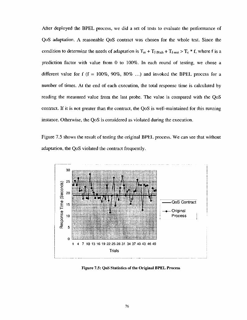
After deployed the BPEL process, we did a set of tests to evaluate the performance of
QoS adaptation. A reasonable QoS contract was chosen for the whole test. Since the
condition to determine the needs of adaptation is Tm + Tf.fpath + Tf.rest > Tc * f, where f is a
prediction factor with value from 0 to 100%. In each round of testing, we chose a
different value for f (f = 100%, 90%, 80% ...) and invoked the BPEL process for a
number of times. At the end of each execution, the total response time is calculated by
reading the measured value from the last probe. The value is compared with the QoS
contract. If it is not greater than the contract, the QoS is well-maintained for this running
instance. Otherwise, the QoS is considered as violated during the execution.
Figure 7.5 shows the result of testing the original BPEL process. We can see that without
adaptation, the QoS violated the contract frequently.
30 , - _ _ _ - ^ .
QoS Contract
—•— Original Process
1 4 7 10 13 16 19 22 25 28 31 34 37 40 43 46 49
Trials
Figure 7.5: QoS Statistics of the Original BPEL Process

We then instrument the process and test it again with the prediction factor in the broker
set to 100%. The result is shown in Figure 7.6. The global QoS improved a bit compared
to the original process. However, the contract violation still happens quite frequently.
•QoS Contract]
-•—With Adapt. f=100%
0 & 1 4 7 10 13 16 19 22 25 28 3134 37 40 43 46 49
Trials
Figure 7.6: QoS Statistics of the QoS- adaptable BPEL Process with f = 100%
When we set the prediction factor to 90%, the result is shown in Figure 7.7. The global
QoS improved more, and so does the possibility of QoS violation. Still, there are about
30% of instances had un-acceptable QoS at the end.
77

7 10 13 16 19 22 25 28 31 34 37 40 43 46 49
Trials
-QoS Contract
-•—With Adapt. f=90%
Figure 7.7: QoS Statistics of the QoS- adaptable Process with f = 90%
25
to T3 C o o 0)
co. 0)
E f-d) u> c o Q_ to CD DC
20
15
10
5
-QoS Contract
• With Adapt. f=80%
1 4 7 10 13 16 19 22 25 28 31 34 37 40 43 46 49
Trials
Figure 7.8: QoS Statistics of the QoS- adaptable Process with f = 80%
Figure 7.8 is the result after we set the prediction factor to 80%. Finally, we can now
hardly see QoS contract violations.
78
By comparing the results above, we can see that our proposed adaptation architecture
works as expected when an appropriate prediction factor is chosen. If the factor is too
high, the prediction result will be sometimes inaccurate due to the overhead of the
instrumentation.
We can conclude from the test that it is critical to use an appropriate algorithm to
determine the threshold for adaptation. The algorithm should accurately predict the QoS
for non-executed part of the BPEL process. Also it needs to reflect the correct amount of
overhead that the QoS broker introduced.
The test also revealed some limitations of our architecture. The QoS is improved by
changing the execution path, and the execution paths use different partner Web services
and different composition logic to differentiate from each other. When deploying the
process, if the partner Web services that can be found for a given task all have similar
QoS performance, it is possible that none of the alternate execution paths can offer
enough improvement on QoS. On the other hand, the same result might be seen even if
the most optimized composition logic is used in alternate execution paths.
7.3 Summary
In this chapter, we looked into a specific case study to evaluate our architecture. We build
a test bed that contains a QoS broker, a BPEL compiler, and a BPEL process which
invokes a number of dummy partner Web services. We presented the implementation of
the QoS broker and the BPEL compiler. We choose response time as a QoS parameter to
be handled.
79

The test has been performed in different configurations of QoS broker. We modified the
condition for deciding the adaptation threshold in each configuration. The result shows
that the relationship between the adaptation algorithms used in the broker and the
performance of the adaptation. We can achieve a very satisfactory result by tuning the
configuration of the QoS broker.
80
Chapter 8
Conclusion
This chapter gives a summary of the research contributions reported in this thesis.
Potential future work is also pointed out.
8.1 Summary of Contributions
In this paper we proposed an architecture for enabling dynamic QoS adaptation for
composite Web services. Our architecture uses a broker-based scheme where a QoS
broker manages the QoS monitoring and adaptation for BPEL processes. Our main
contributions are:
1. We introduced a method of generating adaptation-enabled BPEL processes through
instrumentation. The instrumentation is done using a BPEL compiler. When the user
provides the BPEL definition files to the BPEL compiler, it analyzes the XML
schema of these files, and instruments the files. The new contents allow for the
BPEL process to communicate with the QoS broker at run-time. The instrumented
contents include: partnerLinkType and partnerLink of the broker, probes, and
pathSelectors. We implemented a prototype of the BPEL compiler which is able to
automatically instrument the BPEL files designed by ActiveBPEL.
2. We proposed a new construct called flexPath for BPEL. This allows the designer to
define multiple alternate execution paths in a BPEL process.
81

3. We built QoS broker's functionalities that are lacking in the related work. The broker
in our architecture supports QoS monitoring and adaptation for BPEL process. Our
broker consists of three main components:
a) Topology Interpreter that is responsible for analyzing the schema of the process;
b) QoS Monitor that monitors the runtime QoS;
c) QoS Adapter that initiates the adaptation according to the QoS status. The QoS
adaptation is achieved by changing the execution path of the BPEL process. The
adapter is able to figure out the best execution path for a given portion of the
process. Another functionality of the adapter is to determine the current QoS
status. It predicts the QoS for the portion of the process that has not been
executed yet. The predicted QoS is then used to decide if the possibility of the
QoS violation is high enough to trigger the adaptation.
4. We also studied the factors that might impact adaptation performance. In order to
evaluate the architecture, we implemented the prototypes of the BPEL compiler and
the QoS broker. An example of BPEL process has been used to test the prototypes.
8.2 Future Work
As future work, a few possible directions can be taken to extend our architecture to
achieve more comprehensive functionalities and better performance:
1. We can extend the architecture to accommodate multiple QoS parameters handling.
This might require mostly the changes on the mechanisms for QoS monitoring,
algorithms to measure the QoS, algorithms to predict the QoS, and algorithms to
calculate potential QoS violations.
82
2. A thorough and complete evaluation and analysis of the architecture can be
undertaken.
3. We can also consider instrumenting the alternate execution paths on-the-fly by
selecting partner Web services dynamically. One of the limitations of our
architecture is that the alternate execution paths are defined statically at the design
phase. The invocation of the partner Web services which form these paths are
therefore defined statically as well. Dynamically binding to partner Web services and
using them to form new execution path may be an approach to increase the flexibility
of the adaptation.
83

References
[Aalst 2003] W.M.P. van der Aalst, "Don't go with the flow: Web services composition standards exposed", IEEE Intelligent Systems, Jan/Feb 2003, vol. 18, pp. 72-76.
[ActiveBPEL] ActiveBPEL open source engine, http://www.activevos.com
[Ali 2003] Ali Shaikhl Ali, Omer F. Rana, Rashid Al-Ali, David W. Walker, "UDDIe: An Extended Registry for Web Services", Workshop on Service Oriented Computing: Models, Architectures and Applications, IEEE Computer Society Press, Florida, USA, January 2003.
[Canfora 2005] G. Canfora, M.D. Penta, R. Esposito, M.L. Villani, "QoS-aware replanning of composite Web services", In the Proceedings of the IEEE International Conference on Web Services (ICWS 2005), pp. 121-129, Florida, USA, July 2005.
[Cardoso 2002] J. Cardoso et al., "Modeling quality of service for workflows and web service composition", Technical Report, University of Georgia, 2002.
[Charfi 2004] A. Charfi, M. Mezini, "Aspect-Oriented Web Service Composition with A04BPEL", ECOWS, Erfurt, Germany, 2004.
[Chen 2003] H. Chen, T. Yu, K. J. Lin, "QCWS: an implementation of QoS-capable multimedia Web services", In the Proceedings of Fifth International Symposium on Multimedia Software Engineering, pp. 38-45, Taichung, Taiwan, 2003.
[Courbis 2004] C. Courbis, A. Finkelstein, "Towards an Aspect Weaving BPEL engine", Third AOSD Workshop on Aspects, Components, and Patterns for Infrastructure Software (ACP4IS, a workshop associated with AOSD'04), Lancaster, UK, 2004.
[Dustdar 2005] S. Dustdar, W. Schreiner, "A survey on web services composition", International Journal of Web and Grid Services, vol. 1, No. 1, pp. 1-30, 2005.
[Jaeger 2004] M.C. Jaeger, G. Rojec-Goldmann, G. Muhl, "QoS aggregation for Web service composition using workflow patterns", In the Proceedings of Eighth IEEE International Enterprise Distributed Object Computing Conference (EDOC 2004), pp. 149-159, California, USA, September 2004.
[JDOM] JDOM, http://www.jdom.org/
[Kalepu 2003] S. Kalepu, S. Krishnaswamy, S.W. Loke, "Verity: a QoS metric for selecting Web services and providers", In the Proceedings of Fourth International Conference on Web Information Systems Engineering Workshops (WISE 2003), pp. 131-139, Rome, Italy, December 2003.
84

[Karastoyanova 2004] D. Karastoyanova, A. Buchmann, "Extending Web Service Flow Models to Provide for Adaptability", OOPSLA'04, Vancouver, Canada, 2004.
[Keidl 2003] M. Keidl, S. Seltzsam, A. Kemper, "Reliable Web Service Execution and Deployment in Dynamic Environments", Technologies for E-Services, Springer Berlin / Heidelberg, vol. 2819/2003, pp. 104-118, 2003.
[Khalaf 2003] R. Khalaf, N. Mukhi, S. Weerawarana, "Service-Oriented Composition in BPEL4WS", In the Proceedings of the 12th International World Wide Web Conference (WWW 2003) Alternate Track Papers and Posters, Budapest, Hungary, May 2003.
[Klingemann 2000] J. Klingemann, "Controlled Flexibility in Workflow Management", In the Proceedings of the 12th International Conference on Advanced Information Systems Engineering (CAiSE), pp. 126-141, Stockholm, Sweden, 2000.
[Menasce 2002] D.A. Menasce, "QoS issues in Web services", IEEE Internet Computing, vol. 6, no. 6, pp. 72-75, Nov/Dec 2002.
[Menasce 2004] D.A. Menasce, "Composing Web Services: A QoS View", IEEE Internet Computing, vol. 8, no. 6, pp. 88-90, Nov/Dec 2004.
[Milanovic 2004] N. Milanovic, M. Malek, "Current solutions for Web service composition", IEEE Internet Computing, vol. 8, no. 6, pp. 51-59, Nov/Dec 2004.
[Mujumdar 2005] S. Mujumdar, "Model-Based Framework To Design QoS Adaptive DREApplications", Vanderbilt University, 2005.
[Nahrstedt 2001] K. Nahrstedt, D. Xu, D. Wichadakul, B. Li, "QoS-aware middleware for ubiquitous and heterogeneous environments", IEEE Communications Magazine, vol. 39, no. 11, pp. 140-148, Nov 2001.
[OASIS 2004] "Introduction to UDDI: Important Features and Functional Concepts", http://www.uddi.org/pubs/uddi-tech-wp.pdf, OASIS, 2004.
[OASIS 2006] "Reference Model for Service Oriented Architecture", www.oasis-open.org/committees/download.php/16587/wd-soa-rm-cd 1 ED.pdf, OASIS, 2006.
[OASIS 2007]: "Web Services Business Process Execution Language Version 2.0", http://docs.oasis-open.Org/wsbpel/2.0/wsbpel-v2.0.pdf, OASIS, 2007.
[Onyeka 2007] O. Ezenwoye, S.M. Sadjadi, "TRAP/BPEL: A Framework for Dynamic Adaptation of Composite Services", In Proceedings of the International Conference on Web Information Systems and Technologies (WEBIST-2007), Barcelona, Spain, March 2007.
85

[Papazoglou 2004] Michael P. Papazoglou, Jean-jacques Dubray, "A Survey of Web Service Technologies", Technical Report DIT-04-058, Informatica e Telecomunicazioni, University of Trento, 2004.
[Patel 2003] C. Patel et al., "A QoS Oriented Framework for Adaptive Management of Web Service based Workflows", LNCS Vol. 2736, Springe, pp. 826-835, 2003.
[Petra 1999] P. Heinl, S. Horn, S. Jablonski, J. Neeb, K. Stein, M. Teschke, "A comprehensive approach to flexibility in workflow management systems", ACM SIGSOFT Software Engineering Notes, vol. 24 , Issue 2, pp. 79-88, March 1999.
[Pratistha 2004] I. Pratistha, A. Zaslavsky, "Fluid: supporting a transportable and adaptive web service", In the Proceedings of the 2004 ACM symposium on Applied computing, pp. 1600 -1606, Nicosia, Cyprus, 2004.
[Serhani 2004] M.A. Serhani, "Web Services: Development & QoS Management", Concordia University, 2004.
[Serhani 2005] M.A. Serhani, R. Dssouli, A. Hafid, H. Sahraoui, "A QoS broker based architecture for efficient web services selection", In the Proceedings of 2005 IEEE International Conference on Web Services (ICWS2005), pp. 113-120, Florida, USA, 2005.
[Serhani 2006] M. A. Serhani et al., "CompQoS: Towards an Architecture for QoS composition and monitoring (validation) of composite web services", In the Proceedings of the International Conference on Web Technologies, Application, and Services (WTAS), Calgary, Canada, 2006.
[Silva 2004] JAF da Silva, N das Chagas Mendonca, "Dynamic Invocation of Replicated Web Services", In the Proceedings of the WebMedia & LA-Web 2004 Joint Conference 10th Brazilian Symposium on Multimedia and the Web 2nd Latin American Web Congress (LA-Webmedia'04), pp. 22-28, Ribeirao Preto, Brazil, October 2004.
[Srivastava 2003] B. Srivastava, J. Koehler, "Web service composition: Current solutions and open problems ", In the Proceedings of ICAPS 2003 Workshop on Planning for Web Services, Trento, Italy, June 2003.
[Tian 2004] M. Tian, A. Gramm, H. Ritter, J. Schiller, R. Winter, "A Survey of current Approaches towards Specification and Management of Quality of Service for Web Services", Praxis der Informationsverarbeitung und Kommunikation. Volume 27, Issue 3, pp. 132-139, July/August 2004.
[Verheecke 2004] B. Verheecke, M.A. Cibran, V. Jonckers, "Aspect-Oriented Programming for Dynamic Web Service Monitoring and Selection", Web services, Springer Berlin / Heidelberg, vol. 3250/2004, pp. 15-29, 2004.
86

[Vukovic 2004] M. Vukovic, P. Robinson, "Adaptive, planning based, web service composition for context awareness", International Conference on Pervasive Computing, Vienna, Austria, April 2004.
[W3C 2004] W3C, "Web Service Architecture", http://www.w3.org/TR/2004/NOTE-ws-arch-20040211/, W3C Working Group Note 11, February 2004.
[WebLogic] BEA Weblogic platform, http://www.bea.com
[Yu 2004] J. Yu, G. Zhou, "Dynamic Web Service Invocation Based on UDDI", In the Proceedings of the IEEE International Conference on E-Commerce Technology for Dynamic E-Business (CEC-East'04), pp. 154-157, Beijing, China, September 2004.
[Yu 2005] T. Yu and K. Lin, "A Broker-Based Framework for QoS-Aware Web Service Composition ", In the Proceedings of the 2005 IEEE International Conference on e-Technology, e-Commerce and e-Service (EEE'05) on e-Technology, e-Commerce and e-Service, pp. 22-29, Hong Kong, China, March 2005.
[Zegura 2000] E.W. Zegura, M. H. Ammar, Z. Fei, S. Bhattacharjee, "Application-Layer Anycasting A Server Selection Architecture and Use in a Replicated Web Service", IEEE/ACM Transactions on Networking, Volume 8, Issue 4, pp.455-466, Aug 2000.
[Zeng 2004] L. Zeng, B. Benatallah, A.H.H. Ngu, M. Duma, J. Kalagnanam, H. Chang, "QoS-Aware Middleware for Web Services Composition", IEEE Transactions on Software Engineering, vol. 30, Issue 5, pp. 311-327, May 2004.
87