
NOTE In order to accommodate clearer type, larger charts ... · keep abreast of later information...
83
NOTE In order to accommodate clearer type, larger charts and graphs, and more detailed illustrations, this edition of the IO-320 Series Operator’s Manual, Lycoming Part Number 60297-31 is presented in an 8-1/2 x 11 inch format. This edition is a complete manual, current as of the date of issue. The manual incorporates all previously issued revisions. This manual will be kept current by revisions available from Lycoming distributors or from the factory. All revisions will be accompanied by an Operator’s Manual Revision page which will identify the revision level, the date of the revision, and the pages revised, added or deleted. All revisions will be supplied in the 8-1/2 x 11 inch format.
Transcript of NOTE In order to accommodate clearer type, larger charts ... · keep abreast of later information...
NOTE
In order to accommodate clearer type, larger charts and graphs, and more
detailed illustrations, this edition of the IO-320 Series Operator’s Manual,
Lycoming Part Number 60297-31 is presented in an 8-1/2 x 11 inch
format. This edition is a complete manual, current as of the date of issue.
The manual incorporates all previously issued revisions.
This manual will be kept current by revisions available from Lycoming
distributors or from the factory. All revisions will be accompanied by an
Operator’s Manual Revision page which will identify the revision level, the
date of the revision, and the pages revised, added or deleted. All revisions
will be supplied in the 8-1/2 x 11 inch format.

Operator’s Manual
Lycoming
IO-320 Series
Approved by FAA
3rd Edition Part No. 60297-31
652 Oliver Street
January 2007Williamsport, PA. 17701 U.S.A.570/323-6181

IO-320 Series Operator’s ManualLycoming Part Number: 60297-31
©2006 by Lycoming. All rights reserved.Lycoming and “Powered by Lycoming” are trademarks or registered trademarks ofLycoming.
All brand and product names referenced in this publication are trademarks or registeredtrademarks of their respective companies.
For additional information:
Mailing address:
Lycoming Engines652 Oliver StreetWilliamsport, PA 17701 U.S.A.
Phone:
Factory: 570-323-6181Sales Department: 570-327-7268Fax: 570-327-7101
Lycoming’s regular business hours are Monday through Friday from 8:00 AMthrough 5:00 PM Eastern Time (-5 GMT)
Visit us on the World Wide Web at:http://www.lycoming.textron.com

LYCOMING OPERATOR’S MANUAL
ATTENTION
OWNERS, OPERATORS, AND MAINTENANCE PERSONNEL
gine, its specifications, and detailed information onhow to operate and maintain it. Such maintenance procedures that may be required in conjunction withperiodic inspections are also included. This manual is intended for use by owners, pilots and maintenancepersonnel responsible for care of Lycoming powered aircraft. Modifications and repair procedures arecontained in Lycoming overhaul manuals; maintenance personnel should refer to these for such procedures.
SAFETY WARNING
Neglecting to follow the operating instructions and to carry out periodic maintenance procedures can resultin poor engine performance and power loss. Also, if power and speed limitations specified in this manualare exceeded, for any reason, damage to the engine and personal injury can happen. Consult your localFAA approved maintenance facility.
SERVICE BULLETINS, INSTRUCTIONS, AND LETTERS
Although the information contained in this manual is up-to-date at time of publication, users are urged tokeep abreast of later information through Lycoming Service Bulletins, Instructions and Service Letterswhich are available from all Lycoming distributors or from the factory by subscription. Consult the latestrevision of Service Letter No. L114 for subscription information.
NOTE
The illustrations, pictures and drawings shown in this publication are typical of the subject matter theyportray; in no instance are they to be interpreted as examples of any specific engine, equipment or partthereof.
iii

LYCOMING OPERATOR’S MANUAL
IMPORTANT SAFETY NOTICE
Proper service and repair is essential to increase the safe, reliable operation of all aircraft engines. Theservice procedures recommended by Lycoming are effective methods for performing service operations.Some of these operations require the use of tools specially designed for the task. These special tools must beused when and as recommended.
It is important to note that most Lycoming publications contain various Warnings and Cautions whichmust be carefully read in order to minimize the risk of personal injury or the use of improper servicemethods that may damage the engine or render it unsafe.
It is also important to understand that these Warnings and Cautions are not all inclusive. Lycoming couldnot possibly know, evaluate or advise the service trade of all conceivable ways in which service might bedone or of the possible hazardous consequences that may be involved. Accordingly, anyone who uses aservice procedure must first satisfy themselves thoroughly that neither their safety nor aircraft safety will bejeopardized by the service procedure they select.
iv

WARRANTYNEW AND REBUILT ENGINES
(1) WARRANTY AND REMEDY: Lycoming Engines, a division of Avco Corporation (hereinafter “Lycoming”)warrants each new Lycoming reciprocating engine to be free from defect in material or workmanship under normaluse and service. Lycoming’s sole obligation under this warranty is limited to replacement or repair of parts whichare determined by Lycoming to have been defective within a period of twenty-four (24) months after new aircraftdelivery to the original retail purchaser or first user, or twenty-four (24) months from the date of first operation. Thewarranty period of twenty-four (24) months commences on the earlier of the date of first operation after new aircraftdelivery to the original retail purchaser or first user, or twenty-four (24) months from the date of shipment fromLycoming. Lycoming will, in connection with the foregoing warranty, cover reimbursement of reasonable freightcharges with respect to any such warranty replacement or repair.
(2) Within the warranty period, Lycoming will reimburse the Purchaser for labor charges associated with warrantyrelated issues. Lycoming will only reimburse the cost of such labor charges in connection with repair orreplacement of parts as provided in Lycoming’s then current Removal and Installation Labor and AllowanceGuidebook. Spare parts installed as warranty replacement on engines which are covered by this New EngineWarranty will be warranted for the balance of the original warranty period or for the spare part warranty, whicheveris the greater. Replacement of parts may be with either new or reconditioned parts, at Lycoming’s election. A claimfor warranty on any part claimed to be defective must be reported in writing to Lycoming’s WarrantyAdministration within 60 days of being found to require repair or replacement by the purchaser or service facility.Warranty adjustment is contingent upon the Purchaser complying with the Lycoming’s Warranty Administrationdisposition instructions for defective parts. Failure to comply with all of the terms of this paragraph may, atLycoming’s sole option, void this warranty.
(3) THIS WARRANTY IS GIVEN AND ACCEPTED IN PLACE OF (i) ALL OTHER WARRANTIES ORCONDITIONS, EXPRESS OR IMPLIED, INCLUDING BUT NOT LIMITED TO THE IMPLIED WARRANTIESOR CONDITION OF MERCHANTABILITY AND FITNESS FOR A PARTICULAR PURPOSE AND (ii) ANYOBLIGATION, LIABILITY, RIGHT, CLAIM OR REMEDY IN CONTRACT OR IN TORT (DELICT),INCLUDING PRODUCT LIABILITIES BASED UPON STRICT LIABILITY, NEGLIGENCE, OR IMPLIEDWARRANTY IN LAW AND PURCHASER HEREBY WAIVES SUCH RIGHTS AND CLAIMS.
(4) THIS WARRANTY IS THE ONLY WARRANTY MADE BY LYCOMING. THE PURCHASER’S SOLEREMEDY FOR A BREACH OF THIS WARRANTY OR ANY DEFECT IN A PART IS THE REPAIR ORREPLACEMENT OF ENGINE PARTS AND REIMBURSEMENT OF REASONABLE FREIGHT CHARGES ASPROVIDED HEREIN. LYCOMING EXCLUDES LIABILITY, WHETHER AS A RESULT OF A BREACH OFCONSEQUENTIAL DAMAGES, INCLUDING, BUT NOT LIMITED TO, DAMAGE TO THE ENGINE OROTHER PROPERTY (INCLUDING THE AIRCRAFT IN WHICH THE ENGINE IS INSTALLED), COSTS ANDEXPENSES RESULTING FROM REQUIRED CHANGES OR MODIFICATIONS TO ENGINE COMPONENTSAND ASSEMBLIES, CHANGES IN RETIREMENT LIVES AND OVERHAUL PERIODS, LOCAL CUSTOMSFEES AND TAXES, AND COSTS OR EXPENSES FOR COMMERCIAL LOSSES OR LOST PROFITS DUE TOLOSS OF USE OR GROUNDING OF THE AIRCRAFT IN WHICH THE ENGINE IS INSTALLED OROTHERWISE. LYCOMING’S TOTAL LIABILITY FOR ANY AND ALL CLAIMS RELATED TO ANYENGINE SHALL IN NO CASE EXCEED THE ORIGINAL SALES PRICE OF THE ENGINE. SELLER MAKESNO WARRANTY AND DISCLAIMS ALL LIABILITY WITH RESPECT TO COMPONENTS OR PARTSDAMAGED BY, OR WORN DUE TO, CORROSION.

(5) This warranty shall not apply to any engine or part thereof which has been repaired or altered outsideLycoming’s factory in any way so as, in Lycoming’s sole judgment, to affect its durability, safety or reliability, orwhich has been subject to misuse, negligence or accident. Repairs and alterations which use or incorporate parts andcomponents other than genuine Lycoming parts or parts approved by Lycoming for direct acquisition from sourcesother than Lycoming itself are not warranted by Lycoming, and this warranty shall be void to the extent that suchrepairs and alterations, in Lycoming’s sole judgment, affect the durability, safety or reliability of the engine or anypart thereof, or damage genuine Lycoming or Lycoming-approved parts. No person, corporation or organization,including Distributors of Lycoming engines, is authorized by Lycoming to assume for it any other liability inconnection with the sale of its engines or parts, nor to make any warranties beyond the foregoing warranty nor tochange any of the terms hereof. NO STATEMENT, WHETHER WRITTEN OR ORAL, MADE BY ANYPERSON, CORPORATION OR ORGANIZATION, INCLUDING DISTRIBUTORS OF LYCOMING ENGINESMAY BE TAKEN AS A WARRANTY NOR WILL IT BIND LYCOMING. NO AGREEMENT VARYING THETERMS OF THIS WARRANTY OR LYCOMING’S OBLIGATIONS UNDER IT IS BINDING UPONLYCOMING UNLESS IN WRITING AND SIGNED BY A DULY AUTHORIZED REPRESENTATIVE OFLYCOMING.
(6) All legal actions based upon claims or disputes pertaining to or involving this warranty including, but not limitedto, Lycoming’s denial of any claim or portion thereof under this warranty, must be filed in the courts of generaljurisdiction of Lycoming County, Commonwealth of Pennsylvania or in the United States District Court for theMiddle District of Pennsylvania located in Williamsport, Pennsylvania. In the event that Purchaser files such anaction in either of the court systems identified above, and a final judgment in Lycoming’s favor is rendered by suchcourt, then Purchaser shall indemnify Lycoming for all costs, expenses and attorneys’ fee incurred by Lycoming indefense of such claims. In the event Purchaser files such a legal action in a court other than those specified, andLycoming successfully obtains dismissal of that action or transfer thereof to the above described court systems, thenPurchaser shall indemnify Lycoming for all costs, expenses and attorneys’ fees incurred by Lycoming in obtainingsuch dismissal or transfer.
(7) Any invalidity of a provision of this Warranty shall not affect any other provision, and in the event of a judicialfinding of such invalidity, this Agreement shall remain in force in all other respects.
Effective September 2006 Revision “M”
Ô§½±³·²¹ Û²¹·²»
652 Oliver StreetWilliamsport, Pennsylvania
17701(570) 323-6181
www.lycoming.textron.com

LYCOMING OPERATOR’S MANUAL
TABLE OF CONTENTS
Page
SECTION 1 DESCRIPTION 1-1
SECTION 2 SPECIFICATIONS 2-1
SECTION 3 OPERATING INSTRUCTIONS 3-1
SECTION 4 PERIODIC INSPECTIONS 4-1
SECTION 5 MAINTENANCE PROCEDURES 5-1
SECTION 6 TROUBLE-SHOOTING 6-1
SECTION 7 INSTALLATION AND STORAGE 7-1
SECTION 8 TABLES 8-1
v

LYCOMING OPERATOR’S MANUAL
vi

LYCOMING OPERATOR’S MANUAL
SECTION 1DESCRIPTION
Page
General.......................................................................................................................................................... 1-1
Cylinders....................................................................................................................................................... 1-1
Valve Operating Mechanism ...................................................................................................................... 1-1
Crankcase ..................................................................................................................................................... 1-1
Crankshaft .................................................................................................................................................... 1-1
Connecting Rods .......................................................................................................................................... 1-1
Pistons ........................................................................................................................................................... 1-2
Accessory Housing ....................................................................................................................................... 1-2
Oil Sump ....................................................................................................................................................... 1-2
Cooling System............................................................................................................................................. 1-2
Induction System.......................................................................................................................................... 1-2
Lubrication System...................................................................................................................................... 1-2
Priming System ............................................................................................................................................ 1-3
Ignition System............................................................................................................................................. 1-3
Model Application Table............................................................................................................................. 1-3

This Page Intentionally Left Blank.

LYCOMING OPERATOR’S MANUAL SECTION 1IO-320 SERIES DESCRIPTION
SECTION 1
DESCRIPTION
The IO, AIO and LIO-320 series are four cylinder, direct drive, and horizontally opposed air-cooledengines.
In referring to the location of the various engine components, the parts are described in their relationshipto the engine as installed in the airframe. Thus, the power take-off end is considered the front and theaccessory drive end the rear. The sump section is considered the bottom and the opposite side of the enginewhere the shroud tubes are located the top. Reference to the left and right side is made with the observerfacing the rear of the engine. The cylinders are numbered from front to rear, odd numbers on the right, evennumbers on the left. The direction of rotation for accessory drives is determined with the observer facing thedrive pad. The direction of rotation of the crankshaft, viewed from the rear, is clockwise.
NOTE
The letter “L” in the model prefix denotes the reverse rotation of the basic model. Example:model IO-320-C has clockwise rotation of the crankshaft. Therefore, LIO-320-C hascounterclockwise rotation of the crankshaft. Likewise, the rotation of the accessory drives ofthe LIO-320-C are opposite those of the basic model as listed in Section 2 of this manual
Operational aspects of both engines are the same and performance curves and specificationsfor the basic model will apply to the model with reverse rotation.
Cylinders – The cylinders are of the conventional air-cooled construction with the two major parts, head andbarrel, screwed and shrunk together. The heads are made from an aluminum alloy casting with a fullymachined combustion chamber. Rocker shaft bearing supports are cast integral with the head along withhousings to form the rocker boxes for both valve rockers. The cylinder barrels, which are machined fromchrome nickel molybdenum steel forgings, have deep integral cooling fins and the inside of the barrels areground and honed to a specified finish.
Valve Operating Mechanism – A conventional type camshaft is located above and parallel to the crankshaft.The camshaft actuates hydraulic tappets, which operate the valves through push rods and valve rockers. Thevalves rockers are supported on full floating steel shafts. The valve springs bear against hardened steel seatsand is retained on the valve stems by means of split keys.
Crankcase – The crankcase assembly consists of two reinforced aluminum alloy castings, fastened togetherby means of studs, bolts and nuts. The mating surfaces of the two castings are joined without the use of agasket, and the main bearing bores are machined for use of prevision type main bearing inserts.
Crankshaft – The crankshaft is made from a chrome nickel molybdenum steel forging. All bearing journalsurfaces are nitrided.
Connecting Rods – The connecting rods are made in the formThey have replaceable bearing inserts in the crankshaft ends and bronze bushings in the piston ends. Twobolts and nuts through each cap retain the bearing caps on the crankshaft ends.
1-1
SECTION 1 LYCOMING OPERATOR’S MANUALDESCRIPTION IO-320 SERIES
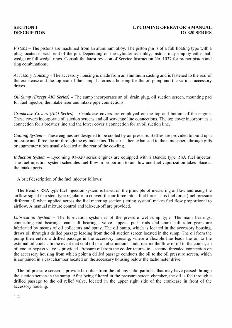
Pistons – The pistons are machined from an aluminum alloy. The piston pin is of a full floating type with aplug located in each end of the pin. Depending on the cylinder assembly, pistons may employ either halfwedge or full wedge rings. Consult the latest revision of Service Instruction No. 1037 for proper piston andring combinations.
Accessory Housing – The accessory housing is made from an aluminum casting and is fastened to the rear ofthe crankcase and the top rear of the sump. It forms a housing for the oil pump and the various accessorydrives.
Oil Sump (Except AIO Series) – The sump incorporates an oil drain plug, oil suction screen, mounting padfor fuel injector, the intake riser and intake pipe connections.
Crankcase Covers (AIO Series) – Crankcase covers are employed on the top and bottom of the engine.These covers incorporate oil suction screens and oil scavenge line connections. The top cover incorporates aconnection for a breather line and the lower cover a connection for an oil suction line.
Cooling System – These engines are designed to be cooled by air pressure. Baffles are provided to build up apressure and force the air through the cylinder fins. The air is then exhausted to the atmosphere through gillsor augmenter tubes usually located at the rear of the cowling.
Induction System – Lycoming IO-320 series engines are equipped with a Bendix type RSA fuel injector.The fuel injection system schedules fuel flow in proportion to air flow and fuel vaporization takes place atthe intake ports.
A brief description of the fuel injector follows:
The Bendix RSA type fuel injection system is based on the principle of measuring airflow and using theairflow signal in a stem type regulator to convert the air force into a fuel force. This fuel force (fuel pressuredifferential) when applied across the fuel metering section (jetting system) makes fuel flow proportional toairflow. A manual mixture control and idle-cut-off are provided.
Lubrication System – The lubrication system is of the pressure wet sump type. The main bearings,connecting rod bearings, camshaft bearings, valve tappets, push rods and crankshaft idler gears arelubricated by means of oil collectors and spray. The oil pump, which is located in the accessory housing,draws oil through a drilled passage leading from the oil suction screen located in the sump. The oil from thepump then enters a drilled passage in the accessory housing, where a flexible line leads the oil to theexternal oil cooler. In the event that cold oil or an obstruction should restrict the flow of oil to the cooler, anoil cooler bypass valve is provided. Pressure oil from the cooler returns to a second threaded connection onthe accessory housing from which point a drilled passage conducts the oil to the oil pressure screen, whichis contained in a cast chamber located on the accessory housing below the tachometer drive.
The oil pressure screen is provided to filter from the oil any solid particles that may have passed throughthe suction screen in the sump. After being filtered in the pressure screen chamber, the oil is fed through adrilled passage to the oil relief valve, located in the upper right side of the crankcase in front of theaccessory housing.
1-2

LYCOMING OPERATOR’S MANUAL SECTION 1IO-320 SERIES DESCRIPTION
This relief valve regulates the engine oil pressure by allowing excessive oil to return to the sump, whilethe balance of the pressure oil is fed to the main oil gallery in the right half of the crankcase. During itstravel through this main gallery, the oil is distributed by means of separate drilled passages to the mainbearings of the crankshaft. Separate passages from the rear main bearings supply pressure oil to bothcrankshaft idler gears. Angular holes are drilled through the main bearings to the rod journals. Oil from themain oil gallery also flows to the cam and valve gear passages, and is then conducted through branchpassages to the hydraulic tappets and camshaft bearings. Oil enters the tappets through indexing holes andtravels out through the hollow push rods to the valve mechanism, lubricating the valve rocker bearings andvalve stems. Residual oil from the bearings, accessory drives and the rocker boxes is returned by gravity tothe sump, where after passing through a screen it is again circulated through the engine. Pressure build upwithin the crankcase is held to a minimum by means of a breather located on the accessory housing.
In addition, model IO-320-C1A incorporates oil jets in the crankcase. The oil jets furnish an oil spray toprovide internal cooling for the pistons.
Priming System – Provision for a primer system is provided on all engines employing a carburetor. Fuelinjected engines do not require a priming system.
Ignition System – Two magnetos furnish dual ignition. Consult Table 1 for model application. Bendixmagnetos are designed to permit periodic internal maintenance; Slick Electro magnetos are designed tooperate approximately 900 hours without internal maintenance.
TABLE 1
MODEL APPLICATIONModel Magnetos DimensionsIO-320 Left Right Height Width Length
-A1A, -A2A* S4LN-200 S4LN-204 19.22 32.24 33.59-B1A, -B2A* S4LN-21 S4LN-20 19.22 32.24 33.59-B1B S4LN-21 S4LN-20 19.22 32.24 33.59-B1C S4LN-21 S4LN-20 19.22 32.24 32.09-B1D S4LN-1208 S4LN-1209 19.22 32.24 32.09-B1E 4251 4250 19.22 32.24 32.09-C1A, -C1B S4LN-21 S4LN-21 19.22 32.24 33.59-D1A, -D1B S4LN-1227 S4LN-1209 23.18 32.24 30.70-D1C 4251 4250 23.19 32.24 29.05-E1A, -E2A* S4LN-21 S4LN-20 23.18 32.24 29.56-E1B 4051 4050 23.19 32.24 29.05-E2B* 4051 4050 23.18 32.24 29.05
AIO-320-A1A, -A2A* S4LN-1208 S4LN-1209 20.76 32.24 30.08-A1B, -A2B* S4LN-1227 S4LN-1209 20.76 32.24 30.08-B1B S4LN-1227 S4LN-1209 20.76 32.24 30.08-C1B S4LN-1227 S4LN-1209 25.57 32.24 30.08
LIO-320-B1A S4RN-21 S4RN-20 19.22 32.24 33.59-C1A S4RN-21 S4RN-21 19.22 32.24 33.59
* - Fixed Pitch Propeller
1-3

This Page Intentionally Left Blank.

LYCOMING OPERATOR’S MANUAL
SECTION 2SPECIFICATIONS
Page
Explanatory Note ......................................................................................................................................... 2-1
Specifications – IO-320-A1A, -A2A, -E1A, -E1B, -E2A, -E2B................................................................. 2-2
Specifications – IO-320-B1A, -B1B, -B1C, -B1D, -B2A, -E1A, -D1B;AIO-320; LIO-320...................................................................................................................................... 2-2
Specifications – IO-320-C1A, -C1B............................................................................................................ 2-2
Specifications – IO-320-B1E, -D1C ............................................................................................................ 2-3
Accessory Drive Ratio.................................................................................................................................. 2-3
Detail Weights .............................................................................................................................................. 2-3

This Page Intentionally Left Blank.

LYCOMING OPERATOR’S MANUAL SECTION 2IO-320 SERIES SPECIFICATIONS
SECTION 2
SPECIFICATIONS
The model specifications shown on the following pages of this section are divided according to modeldesignation. When differences among models can be clearly stated, the specifications of more than onemodel are combined in a single group; otherwise each model has its specifications listed separately. Also, asadditional models are added to this series, new specification pages containing data pertinent to the newmodels will be added.
2-1

SECTION 2 LYCOMING OPERATOR’S MANUALSPECIFICATIONS IO-320 SERIES
SPECIFICATIONS
IO-320-A1A, -A2A, -E1A, -E1B, -E2A, -E2B
FAA Type Certificate ................................................................................................................................. 1E12Rated horsepower...........................................................................................................................................150Rated speed, RPM........................................................................................................................................2700Bore, inches.................................................................................................................................................5.125Stroke, inches..............................................................................................................................................3.875Displacement, cubic inches.........................................................................................................................319.8Compression ratio ....................................................................................................................................... 7.0:1Firing order ............................................................................................................................................. 1-3-2-4Spark occurs, degrees BTC..............................................................................................................................25Valve rocker clearance (hydraulic tappets collapsed) ......................................................................... .028-.080Propeller drive ratio ....................................................................................................................................... 1:1Propeller drive rotation (viewed from rear) ........................................................................................Clockwise
IO-320-B1A, -B1B, -B1C, -B1D, -B2A, -D1A, -D1B; AIO-320; LIO-320
FAA Type Certificate ................................................................................................................................. 1E12Rated horsepower...........................................................................................................................................160Rated speed, RPM........................................................................................................................................2700Bore, inches.................................................................................................................................................5.125Stroke, inches..............................................................................................................................................3.875Displacement, cubic inches.........................................................................................................................319.8Compression ratio ....................................................................................................................................... 8.5:1Firing order* ........................................................................................................................................... 1-3-2-4Spark occurs, degrees BTC..............................................................................................................................25Valve rocker clearance (hydraulic tappets collapsed) ......................................................................... .028-.080Propeller drive ratio ....................................................................................................................................... 1:1Propeller drive rotation
All but LIO-320 Series......................................................................................................................ClockwiseLIO-320 Series......................................................................................................................Counterclockwise
IO-320-C1A, -C1B
FAA Type Certificate ................................................................................................................................. 1E12Rated horsepower...........................................................................................................................................160Rated speed, RPM........................................................................................................................................2700Bore, inches.................................................................................................................................................5.125Stroke, inches..............................................................................................................................................4.375Displacement, cubic inches.........................................................................................................................319.8Compression ratio ....................................................................................................................................... 8.5:1Firing order* ........................................................................................................................................... 1-3-2-4Spark occurs, degrees BTC..............................................................................................................................25Valve rocker clearance (hydraulic tappets collapsed) ......................................................................... .028-.080Propeller drive ratio ....................................................................................................................................... 1:1Propeller drive rotation
All but LIO-320 Series......................................................................................................................ClockwiseLIO-320 Series......................................................................................................................Counterclockwise
* - LIO-320 Series Only
2-2

LYCOMING OPERATOR’S MANUAL SECTION 2IO-320 SERIES SPECIFICATIONS
SPECIFICATIONS (CONT.)
IO-320-B1E, -D1C
FAA Type Certificate ................................................................................................................................. 1E12Rated horsepower...........................................................................................................................................160Rated speed, RPM........................................................................................................................................2700Bore, inches.................................................................................................................................................5.125Stroke, inches..............................................................................................................................................4.875Displacement, cubic inches.........................................................................................................................319.8Compression ratio ....................................................................................................................................... 8.5:1Firing order ............................................................................................................................................. 1-3-2-4Spark occurs, degrees BTC..............................................................................................................................25Valve rocker clearance (hydraulic tappets collapsed) ......................................................................... .028-.080Propeller drive ratio ....................................................................................................................................... 1:1Propeller drive rotation (viewed from rear) ........................................................................................Clockwise
*Accessory Drive Drive Ratio **Direction of Rotation
Starter 13.556:1 CounterclockwiseStarter 16.556:1 CounterclockwiseGenerator 1.910:1 ClockwiseGenerator 2.500:1 ClockwiseAlternator 3.250:1 ClockwiseTachometer 0.500:1 ClockwiseMagneto 1.000:1 ClockwiseVacuum Pump 1.300:1 CounterclockwiseProp. Gov. AN20010
Mounted on Accy. Hsg. 0.866:1 ClockwiseMounted on Crankcase 0.895:1 Clockwise
Fuel Pump AN20003 1.000:1 Counterclockwise
Dual Drives
* - When applicable.** - Viewed facing drive pad.
NOTE that LIO-320 series engines will have opposite rotation to the above.
DETAIL WEIGHTS
1. Engine, Standard, Dry Weight.
Includes fuel injector, magnetos, spark plugs, ignition harness, intercylinder baffles, tachometer drive,starter and generator (alternator) drive, starter and generator (alternator) with mounting bracket.
2-3

SECTION 2 LYCOMING OPERATOR’S MANUALSPECIFICATIONS IO-320 SERIES
DETAIL WEIGHTS (CONT.)
IO-320 SERIES
LBS.
-A1A, -A2A ...................................................................................................................................................280-E1B ...............................................................................................................................................................283-B1B, -E1A, -E2A, -E2B ...............................................................................................................................285-B1A, -B2A, -B1C .........................................................................................................................................287-B1D...............................................................................................................................................................288-D1A ..............................................................................................................................................................291-D1B...............................................................................................................................................................293-C1A...............................................................................................................................................................301-D1C...............................................................................................................................................................306-B1E ...............................................................................................................................................................307-C1B...............................................................................................................................................................313
AIO-320 SERIES
LBS.
-A1A, -A2A ...................................................................................................................................................306-A1B, A2B, -B1B, -C1B................................................................................................................................307
2-4

LYCOMING OPERATOR’S MANUAL
SECTION 3OPERATING INSTRUCTIONS
Page
General.......................................................................................................................................................... 3-1
Prestarting Items of Maintenance .............................................................................................................. 3-1
Starting Procedures ..................................................................................................................................... 3-1
Cold Weather Starting ................................................................................................................................ 3-2
Ground Running and Warm-Up................................................................................................................ 3-2
Ground Check .............................................................................................................................................. 3-3
Operation in Flight ...................................................................................................................................... 3-4
Fuel Mixture Leaning Procedure ........................................................................................................... 3-4
Leaning to Exhaust Gas Temperature Gage ..................................................................................... 3-4
Leaning to Flowmeter.......................................................................................................................... 3-5
Leaning with Manual Mixture Control ............................................................................................. 3-5
Engine Flight Chart ..................................................................................................................................... 3-5
Operating Conditions .................................................................................................................................. 3-6
Engine Shut Down ....................................................................................................................................... 3-7
Performance Curves .................................................................................................................................... 3-9

This Page Intentionally Left Blank.
LYCOMING OPERATOR’S MANUAL SECTION 3IO-320 SERIES OPERATING INSTRUCTIONS
SECTION 3
OPERATING INSTRUCTIONS
1. GENERAL. Close adherence to these instructions will greatly contribute to long life, economy andsatisfactory operation of the engine.
NOTE
YOUR ATTENTION IS DIRECTED TO THE WARRANTIES THAT APPEAR IN THEFRONT OF THIS MANUAL REGARDING ENGINE SPEED, THE USE OF SPECIFIEDFUELS AND LUBRICANTS, REPAIRS AND ALTERATIONS. PERHAPS NO OTHER ITEMOF ENGINE OPERATION AND MAINTENANCE CONTRIBUTES QUITE SO MUCH TOSATISFACTORY PERFORMANCE AND LONG LIFE AS THE CONSTANT USE OFCORRECT GRADES OF FUEL AND OIL, CORRECT ENGINE TIMING, AND FLYINGTHE AIRCRAFT AT ALL TIMES WITHIN THE SPEED AND POWER RANGE SPECIFIEDFOR THE ENGINE. DO NOT FORGET THAT VIOLATION OF THE OPERATION ANDMAINTENANCE SPECIFICATIONS FOR YOUR ENGINE WILL NOT ONLY VOID YOURWARRANTY BUT WILL SHORTEN THE LIFE OF YOUR ENGINE AFTER ITS WARRANTYPERIOD HAS PASSED.
New engines have been carefully run-in by Lycoming; therefore, no further break-in is necessary insofaras operation is concerned; however, new or newly overhauled engines should be operated on straightmineral oil for a minimum of 50 hours or until oil consumption has stabilized. After this period, a change toan approved additive oil may be made, if so desired.
NOTE
Cruising should be done at 65% to 75% power until a total of 50 hours has accumulated oroil consumption has stabilized. This is to ensure proper seating of the rings and is applicableto new engines, and engines in service following cylinder replacement or top overhaul of oneor more cylinders.
The minimum fuel octane rating is listed in the flight chart, Part 8 of this section. Under no circumstancesshould fuel of a lower octane rating or automotive fuel (regardless of octane rating) be used.
2. PRESTARTING ITEMS OF MAINTENANCE. Before starting the aircraft engine for the first flight of theday, there are several items of maintenance inspection that should be performed. These are described inSection 4 under Daily Pre-Flight Instruction. They must be observed before the engine is started.
3. STARTING PROCEDURES.
The following starting procedures are recommended, however, the starting characteristics of variousinstallations will necessitate some variation from these procedures.
NOTE
Cranking periods must be limited to ten (10) to twelve (12) seconds with a five (5) minuterest between cranking periods.
3-1
SECTION 3 LYCOMING OPERATOR’S MANUALOPERATING INSTRUCTIONS IO-320 SERIES
a. Fuel Injected Engines (Cold).
(1) Perform preflight inspection.
(6) Open throttle wide open, move until a slight but steady flow isnoted (approximately 3 to 5 second
(8) Open throttle ¼ of travel.
(9) Set magneto selector switch. (Consult airf
(10) Engage starter.
(12) Move mixture control slowly
(13) Check oil pressure gage. If minimum oil pressure is not indicated within thirty seconds, stopengine and determine trouble.
b. Fuel Injected Engines (Hot). Because of the fact that the fuel percolates and the system must becleared of vapor, it is recommended that the same procedure be used as outlined for cold engine start.
4. COLD WEATHER STARTING. During extreme cold weather, it may be necessary to preheat the engineand oil before starting.
5. GROUND RUNNING AND WARM-UP.
The engines covered in this manual are air-pressure cooled and depend on the forward speed of the aircraftto maintain proper cooling. Particular care is necessary, therefore, when operating these engines on theground. To prevent overheating, it is recommended that the following precautions be observed.
NOTE
Any ground check that requires full throttle operation must be limited to three minutes, orless if the indicated cylinder head temperature should exceed the maximum stated in thismanual.
3-2

LYCOMING OPERATOR’S MANUAL SECTION 3IO-320 SERIES OPERATING INSTRUCTIONS
a. Head the aircraft into the wind.
c. Operate only with the propeller in minimum blade angle setting.
d. Warm-up at approximately 1000-1200 RPM. Avoid prolonged idling and do not exceed 2200 RPM onthe ground.
e. Engine is warm enough for take-off when the throttle can be opened without the engine faltering.
6. GROUND CHECK.
a. Warm-up as directed above.
b. Check both oil pressure and oil temperature.
d. (Where applicable.) Move the propeller control through its complete range to check operation andreturn to full low pitch position. Full feathering check (twin engine) on the ground is notrecommended but the feathering action can be checked by running the engine between 1000-1500RPM; then momentarily pulling the propeller control into the feathering position. Do not allow theRPM to drop more than 500 RPM.
e. A proper magneto check is important. Additional factors, other than the ignition system, affectmagneto drop-off. They are load-power output, propeller pitch and mixture strength. The importantthing is that the engine runs smoothly because magneto drop-off is affected by the variables listedabove. Make the magneto check in accordance with the following procedures.
(1) Controllable Pitch Propeller – With propeller in minimum pitch angle, set the engine to produce50-65% power as indicated by the manifold pressure gage. Mixture control should be in the fullrich position. At these settings, the ignition system and spark plugs must work harder because ofthe greater pressure within the cylinders. Under these conditions ignition problems, if they exist,will occur. Magneto checks at low power settings will only indicate fuel-air distribution quality.
NOTE
Aircraft that are equipped with fixed pitch propeller, or not equipped with manifold pressuregage, may check magneto drop-off with engine operating at a maximum of 2000-2100 RPM.
(2) Switch from both magnetos to one and note drop-off, return to both until engine regains speed andswitch to the other magneto and note drop-off, then return to both. Drop-off should not exceed 175RPM and should not exceed 50 RPM between magnetos. A smooth drop-off past normal is usuallya sign of a too lean or too rich mixture.
f. Do not operate on a single magneto for too long a period, a few seconds is usually sufficient to checkdrop-off and will minimize plug fouling.
3-3

SECTION 3 LYCOMING OPERATOR’S MANUALOPERATING INSTRUCTIONS IO-320 SERIES
7. OPERATION IN FLIGHT.
ctions for recommended power settings.
b. Fuel Mixture Leaning Procedure.
Improper fuel/air mixture during flight is responsible for many engine problems, particularly duringtake-off and climb power settings. The procedures described in this manual provide proper fuel/airmixture when leaning Lycoming engines; they have proven to be both economical and practical byeliminating excessive fuel consumption and reducing damaged parts replacement. It is thereforerecommended that operators of all Lycoming aircraft power plants utilize the instructions in thispublication any time the fuel/air mixture is adjusted during flight.
Manual leaning may be monitored by exhaust gas temperature indication, fuel flow indication, andby observation of engine speed and/or airspeed. However, whatever instruments are used inmonitoring the mixture, the following general rules should be observed by the operator of Lycomingengines.
GENERAL RULES
Never exceed the maximum red line cylinder head temperature limit.
For maximum service life, cylinder head temperatures should be maintained below 435°F(224°C) during high performance cruise operation and below 400°F (205°C) for economycruise powers.
Do not manually lean engines equipped with automatically controlled fuel system.
Maintain mixture control in “Full Rich” position for rated take-off, climb and maximumcruise powers (above approximately 75%). However, during take-off from high elevationairport or during climb, roughness or loss of power may result from over-richness. In such acase adjust mixture control only enough to obtain smooth operation – not for economy.Observe instruments for temperature rise.
Always return the mixture to full rich before increasing power settings.
Operate the engine at maximum power mixture for performance cruise powers and at besteconomy mixture for economy cruise power; unless otherwise specified in the airplaneowners manual.
During let-down flight operations it may be necessary to manually lean uncompensatedfuel injected engines to obtain smooth operation.
1. LEANING TO EXHAUST GAS TEMPERATURE GAGE.
a. Normally aspirated engines with fuel injectors.
3-4

LYCOMING OPERATOR’S MANUAL SECTION 3IO-320 SERIES OPERATING INSTRUCTIONS
(1) Maximum Power Cruise (approximately 75% power) – Never lean beyond 150°F onrich side of peak EGT unless aircraft operator’s manual shows otherwise. Monitorcylinder head temperatures.
(2) Best Economy Cruise (approximately 75% power and below) – Operate at peakEGT, or if desired, drop 50°F on rich side of peak EGT.
2. LEANING TO FLOWMETER.
Lean to applicable fuel-flow tables or lean to indicator marked for correct fuel-flow foreach power setting.
3. LEANING WITH MANUAL MIXTURE CONTROL (Economy Cruise, 75% power or less)without flowmeter or EGT gage.
a. Fuel Injected Engines.
(1) Slowly move mixture control from “Full Rich” position toward lean position.
(2) Continue leaning until slight loss of power is noted (loss of power may or may not beaccomplished by roughness).
(3) Enrich until engine runs smoothly and power is regained.
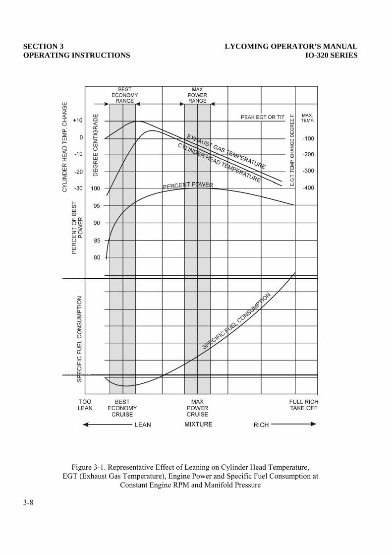
As shown in Figure 3-1, if engine speed and throttle setting are kept constant at normal cruise conditions,the affect of leaning on engine power and engine temperatures will be as shown. Power drops rapidly whenthe engine is leaned beyond peak exhaust gas temperature; also, best power is attained on the rich side ofpeak exhaust gas temperature.
8. ENGINE FLIGHT CHART.
Model Aviation Grade Fuel
IO-320-A1A, -A2A, -E1A, -E2A, -E1B, -E2B 80/87 octane, minimumIO-320-B1A, -B2A, -B2B, -B2C, -B1D 91/96 or 100/130 octane, minimumIO-320-D1A, -D1B 91/96 or 100/130 octane, minimumIO-320-B1E, -C1A, -C1B, -D1C 100/100LL octane, minimumAIO-320 Series 91/96 or 100/130 octane, minimumLIO-320-B Series 91/96 or 100/130 octane, minimumLIO-320-C Series 100/130 octane, minimum
NOTE: Aviation grade 100LL fuels in which the lead content is limited to 2 c.c. per gal. are approved forcontinuous use in the above listed engines.
3-5

SECTION 3 LYCOMING OPERATOR’S MANUALOPERATING INSTRUCTIONS IO-320 SERIES
ALL MODELS
*Recommended Grade OilAverage MIL-L-6082 Ashless Dispersant
Ambient Air Grades Grades
Above 80°F (26.66°C) SAE 60 SAE 60Above 60°F (15.55°C) SAE 50 SAE 40 or SAE 5030°F to 90°F (-1.11°C to 32.22°C) SAE 40 SAE 40
0°F to 70°F (-17.77°C to 21.11°C) SAE 20 SAE 30 or SAE 40Below 10°F (-12.22°C) SAE 20 SAE 30
* - Refer to the latest edition of Service Instruction No. 1014.
Oil Sump Capacity.........................................................................................................................8 U.S. Quarts
Minimum Safe Quantity in Sump..................................................................................................2 U.S. Quarts
OPERATING CONDITIONS
Average Oil Inlet TemperatureAmbient Air Desired Maximum
Above 80°F (26.66°C) 180°F (82°C) 245°F (118°C)Above 60°F (15.55°C) 180°F (82°C) 245°F (118°C)30°F to 90°F (-1.11°C to 32.22°C) 180°F (82°C) 245°F (118°C)
0°F to 70°F (-17.77°C to 21.11°C) 170°F (77°C) 225°F (107°C)Below 10°F (-12.22°C) 160°F (71°C) 210°F ( 99°C)
Oil Pressure, psi Maximum Minimum Idling
Normal Operating 90 60 25Start and Warm-Up 100
Fuel Pressure, psi Maximum Desired Min.
IO-320-B, -D, -E Series;AIO-320; LIO-320-B
Inlet to fuel pump 35 ----- -2Inlet to fuel injector 45 ----- 12Inlet to fuel pump with
injector in idle cut-off 55 ----- ----
IO-320-C Series; LIO-320-CInlet to fuel pump 45 ----- -2Inlet to fuel injector 45 ----- 14Inlet to fuel pump with
injector in idle cut-off 55 ----- ----
3-6

LYCOMING OPERATOR’S MANUAL SECTION 3IO-320 SERIES OPERATING CONDITIONS
OPERATING CONDITIONS (CONT.)
Fuel Max. *Max.Cons. Oil Cons. Cyl.Head
Operation RPM HP Gal./Hr. Qts./Hr. Temp.
IO-320-A, -E Series
Normal Rated 2700 150 ----- .67 500°F (260°C)Performance Cruise
(75% Rated) 2450 110 10.0 .37 500°F (260°C)Economy Cruise
(65% Rated) 2350 97 8.8 .33 500°F (260°C)
IO-320-B, -C, -D; AIO-320; LIO-320 Series
Normal Rated 2700 160 ----- .72 500°F (260°C)Performance Cruise
(75% Rated) 2450 120 10.0 .40 500°F (260°C)Economy Cruise
(65% Rated) 2350 104 8.8 .35 500°F (260°C)
the engine, maintain cylinder head temperaturesbetween 150°F and 435°F during continuous operation.
9. ENGINE SHUT-DOWN.
a. Set propeller at minimum blade angle (where applicable).
b. Idle until there is a decided decrease in cylinder head temperature.
d. When engine stops, turn ignition switch off.
3-7
SECTION 3 LYCOMING OPERATOR’S MANUALOPERATING INSTRUCTIONS IO-320 SERIES
Figure 3-1. Representative Effect of Leaning on Cylinder Head Temperature,EGT (Exhaust Gas Temperature), Engine Power and Specific Fuel Consumption at
Constant Engine RPM and Manifold Pressure
3-8

LYCOMING OPERATOR’S MANUAL SECTION 3IO-320 SERIES OPERATING INSTRUCTIONS
IO-320-A, -E Series
3-9

SECTION 3 LYCOMING OPERATOR’S MANUALOPERATING INSTRUCTIONS IO-320 SERIES
IO-320-A Series
3-10

LYCOMING OPERATOR’S MANUAL SECTION 3IO-320 SERIES OPERATING INSTRUCTIONS
IO-320-E Series
3-11

SECTION 3 LYCOMING OPERATOR’S MANUALOPERATING INSTRUCTIONS IO-320 SERIES
IO-320-B, -D Series; AIO-320; LIO-320-B
3-12

LYCOMING OPERATOR’S MANUAL SECTION 3IO-320 SERIES OPERATING INSTRUCTIONS
IO-320-B, -D; AIO-320; LIO-320
3-13

SECTION 3 LYCOMING OPERATOR’S MANUALOPERATING INSTRUCTIONS IO-320 SERIES
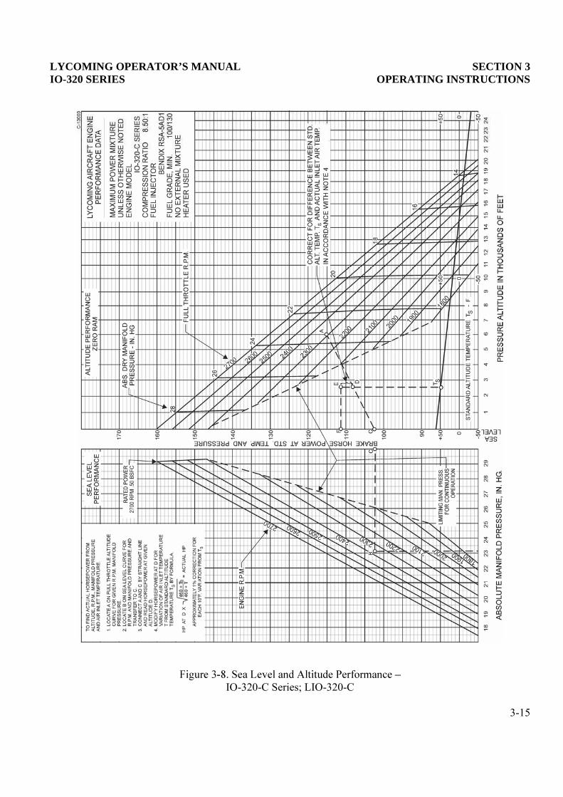
IO-320-C Series; LIO-320-C
3-14
LYCOMING OPERATOR’S MANUAL SECTION 3IO-320 SERIES OPERATING INSTRUCTIONS
IO-320-C Series; LIO-320-C
3-15

This Page Intentionally Left Blank.

LYCOMING OPERATOR’S MANUAL
SECTION 4PERIODIC INSPECTIONS
Page
General.......................................................................................................................................................... 4-1
Pre-Starting Inspection ............................................................................................................................... 4-1
Daily Pre-Flight............................................................................................................................................ 4-2
25-Hour Inspection ...................................................................................................................................... 4-2
50-Hour Inspection ...................................................................................................................................... 4-2
100-Hour Inspection .................................................................................................................................... 4-3
400-Hour Inspection .................................................................................................................................... 4-4
Non-Scheduled Inspection........................................................................................................................... 4-4

This Page Intentionally Left Blank.

LYCOMING OPERATOR’S MANUAL SECTION 4IO-320 SERIES PERIODIC INSPECTIONS
SECTION 4
PERIODIC INSPECTIONS
NOTE
Perhaps no other factor is quite so important to safety and durability of the aircraft and itscomponents as faithful and diligent attention to regular checks for minor troubles andprompt repair when they are found.
The operator should bear in mind that the items listed in the following pages do notconstitute a complete aircraft inspection, but are meant for the engine only. Consult theairframe manufacturer’s handbook for additional instructions.
Pre-Starting Inspection – The daily pre-flight inspection is a check of the aircraft prior to the first flight ofthe day. This inspection is to determine the general condition of the aircraft and engine.
The importance of proper pre-flight inspection cannot be over emphasized. Statistics prove severalhundred accidents occur yearly directly responsible to poor pre-flight inspection.
Among the major causes of poor pre-flight inspection are lack of concentration, reluctance toacknowledge the need for a check list, carelessness bred by familiarity and haste.
4-1
SECTION 4 LYCOMING OPERATOR’S MANUALPERIODIC INSPECTIONS IO-320 SERIES
1. DAILY PRE-FLIGHT.
b. Be sure magneto ground wires are connected.
c. Check oil level.
d. See that fuel tanks are full.
e. Check fuel and oil connections, note minor indications for repair at 50-hour inspection. Repair anymajor leaks before aircraft is flown.
f. Open the fuel drain to remove any accumulation of water and sediment.
g. Make sure all shields and cowling are in place and secure. If any are missing or damaged, repair orreplacement should be made before the aircraft is flown.
h. Check controls for general condition, travel and freedom of operation.
i. Induction system air filter should be inspected and serviced in accordance with the airframe
2. 25-HOUR INSPECTION. After the first twenty-five hours operating time, new, rebuilt, or newlyoverhauled engines should undergo a 50-hour inspection including draining and renewing lubricating oil.Engines equipped with oil pressure screen are required to comply with the following inspection after every25 hours of operating time.
a. Lubrication System (Engines Equipped with Oil Pressure Screen)-
(1) Remove oil suction and oil pressure screens and check carefully for presence of metal particlesthat are indicative of internal engine damage. Clean and reinstall the oil suction and oil pressurescreens. Drain and renew the lubricating oil.
NOTE
Change the oil at least every four (4) months even if the engine has not accumulated 25hours since the last oil change.
3. 50-HOUR INSPECTION. In addition to the items listed for daily pre-flight inspection, the followingmaintenance checks should be made after every 50 hours of operation.
a. Ignition System –
(1) If fouling of spark plugs has been apparent, rotate bottom plugs to upper position.
(2) Examine spark plug leads of cable and ceramics for corrosion and deposits. This condition isevidence of either leaking spark plugs, improper cleaning of the spark plug walls or connectorends. Where this condition is found, clean the cable ends, spark plug walls and ceramics with adry, clean cloth or a clean cloth moistened with methyl-ethyl-ketone. All parts should be clean anddry before reassembly.
4-2

LYCOMING OPERATOR’S MANUAL SECTION 4IO-320 SERIES PERIODIC INSPECTIONS
(3) Check ignition harness for security of mounting clamps and be sure connections are tight at sparkplug and magneto terminals.
b. Fuel and Induction System – Check the primer lines (where applicable) for leaks and security of theclamps. Remove and clean the fuel inlet strainers. Check the mixture control and throttle linkage fortravel, freedom of movement, security of the clamps and lubricate if necessary. Check the air intakeducts for leaks, security, filter damage; evidence of dust or other solid material in the ducts isindicative of inadequate filter care or damaged filter. Check vent lines for evidence of fuel or oilseepage; if present, fuel pump may require replacement.
c. Lubrication System (Engines Equipped with an External Full Flow Oil Filter) –
(1) Remove oil suction and oil pressure screens and check carefully for presence of metal particlesthat are indicative of internal engine damage.
(2) Replace external full flow oil filter element. Drain and renew lubricating oil.
NOTE
Change the oil at least every four (4) months event if the engine has not accumulated 50hours since the last oil change.
(3) Check oil leaks, particularly at connections for security of anchorage and for wear due to rubbingor vibration, for dents and cracks.
d. Exhaust System – Check attaching flanges at exhaust ports on cylinder for evidence of leakage. If theyare loose, they must be removed and machined flat before they are reassembled and tightened.Examine exhaust manifolds for general condition.
e. Cooling System – Check cowling and baffles for damage and secure anchorage. Any damaged ormissing part of the cooling system must be repaired or replaced before the aircraft resumes operation.
f. Cylinders – Check rocker box covers for evidence of oil leaks. If found, replace gasket and tightenscrews to specified torque (50 inch lbs.).
Check cylinders for evidence of excessive heat which is indicated by burned paint on the cylinder.This condition is indicative of internal damage to the cylinder and, if found, its cause must bedetermined and corrected before the aircraft resumes operation.
4. 100-HOUR INSPECTION. In addition to the items listed for daily pre-flight and 50-hour inspection, thefollowing maintenance checks should be made after every one hundred hours of operation.
a. Electrical System –
(1) Check all wiring connected to the engine or accessories. Any shielded cables that are damagedshould be replaced. Replace clamps or loose wires and check terminals for security andcleanliness.
(2) Remove spark plugs; test, clean and regap. Replace if necessary.
4-3

SECTION 4 LYCOMING OPERATOR’S MANUALPERIODIC INSPECTIONS IO-320 SERIES
b. Magnetos – Check breaker points for pitting and minimum gap. Check for excessive oil in the breakercompartment, if found, wipe dry with a clean lint free cloth. The felt located at the breaker pointsshould be lubricated in accordance with the magne ions. Check magneto toengine timing. Timing procedure is described in Section 5, 1, b of this manual.
c. Engine Accessories – Engine mounted accessories such as pumps, temperature and pressure sensingunits should be checked for secure mounting, tight connections.
d. Cylinders – Check cylinders visually for cracked or broken fins.
e. Engine Mounts – Check engine mounting bolts and bushings for security and excessive wear. Replaceany bushings that are excessively worn.
f. Fuel Injector Nozzles and Fuel Lines – Check fuel injector nozzles for looseness. Tighten to 60 inchpounds torque. Check fuel lines for fuel stains which are indicative of fuel leaks. Repair orreplacement must be accomplished before the aircraft resumes operation.
5. 400-HOUR INSPECTION – In addition to the items listed for daily pre-flight, 50-hour and 100-hourinspections, the following maintenance check should be made after every 400 hours of operation.
Valve Inspection – Remove rocker box covers and check for freedom of valve rockers when valves areclosed. Look for evidence of abnormal wear or broken parts in the area of the valve tips, valve keeper,springs and spring seats. If any indications are found, the cylinder and all of its components should beremoved (including the piston and connecting rod assembly) and inspected for further damage. Replace anyparts that do no conform with limits shown in the latest revision of Special Service Publication No. SSP-1776.
6 NON-SCHEDULED INSPECTIONS. Occasionally, service bulletins or service instructions are issued byLycoming Engines that require inspection procedures that are not listed in this manual. Such publications,usually are limited to specified engine models and become obsolete after corrective modification has beenaccomplished. All such publications are available from Lycoming distributors, or from the factory bysubscription. Consult the latest revision of Service Letter No. L114 for subscription information.Maintenance facilities should have an up-to-date file of these publications available at all times.
4-4

LYCOMING OPERATOR’S MANUAL
SECTION 5MAINTENANCE PROCEDURES
Page
General.......................................................................................................................................................... 5-1
Ignition and Electrical System
Ignition Harness and Wire Replacement................................................................................................ 5-1
Timing Magneto to Engine
Bendix Magneto ..................................................................................................................................... 5-1
Slick Magneto ......................................................................................................................................... 5-1
Fuel System
Repair of Fuel Leaks................................................................................................................................. 5-4
Fuel Injector Fuel Inlet Screen Assembly............................................................................................... 5-4
Fuel Grade and Limitations..................................................................................................................... 5-5
Air Intake Ducts and Filter...................................................................................................................... 5-5
Idle Speed and Mixture Adjustment ....................................................................................................... 5-5
Lubrication System
Oil Grades and Limitations...................................................................................................................... 5-5
Oil Suction and Oil Pressure Screens ..................................................................................................... 5-6
Oil Pressure Relief Valve.......................................................................................................................... 5-6
Cylinders....................................................................................................................................................... 5-6
Generator or Alternator Belt Tension ..................................................................................................... 5-10

This Page Intentionally Left Blank.

LYCOMING OPERATOR’S MANUAL SECTION 5IO-320 SERIES MAINTENANCE PROCEDURES
SECTION 5
MAINTENANCE PROCEDURES
The procedures described in this section are provided to guide and instruct personnel in performing suchmaintenance operations that may be required in conjunction with the periodic inspections listed in thepreceding section. No attempt is made to include repair and replacement operations that will be found in theapplicable Lycoming Overhaul Manual.
1. IGNITION AND ELECTRICAL SYSTEM.
a. Ignition Harness and Wire Replacement – In the event that an ignition harness or an individual lead isto be replaced, consult the wiring diagram to be sure harness is correctly installed. Mark location ofclamps and clips to be certain the replacement is clamped at correct locations.
b. Timing Magnetos to Engine – Although several combinations of magnetos are used on this seriesengine, (see Table of Models for model application) the timing procedures, with the exception of themethod of turning the magnetos to the correct breaker position, are the same for all magnetos.
NOTE
Either the impulse coupling or retard breaker magneto (whichever is applicable) is installedon the left side of the engine.
(1) Remove a spark plug from No. 1 cylinder and place a thumb over the spark plug hole. Rotate thecrankshaft in direction of normal rotation until the compression stroke is reached, this is indicatedby a positive pressure inside the cylinder tending to push the thumb off the spark plug hole.Continue rotating the crankshaft until the advance timing mark on the front face of the starter ringgear is in exact alignment with the small hole lo position on the front faceof the starter housing. (Starter ring gear may be marked at 20° and 25°. Consult enginespecifications or nameplate for correct timing mark of your installation.)
NOTE
If the crankshaft is accidentally turned in the direction opposite normal rotation, repeat theabove procedure as accumulated backlash will make the final timing incorrect.
(2) At this point, the engine is ready for assembly of the magnetos.
(a) Bendix Magnetos – Remove the inspection plugs from both magnetos and turn the drive shaft indirection of normal rotation until the first painted chamfered tooth on the distributor gear isaligned in the center of the inspection window.
(b) Slick Magnetos –accomplished in the following manner.
5-1
SECTION 5 LYCOMING OPERATOR’S MANUALMAINTENANCE PROCEDURES IO-320 SERIES
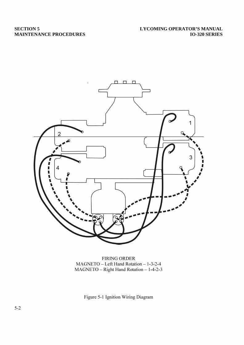
FIRING ORDER
Figure 5-1 Ignition Wiring Diagram
5-2

LYCOMING OPERATOR’S MANUAL SECTION 5IO-320 SERIES MAINTENANCE PROCEDURES
FIRING ORDER
Figure 5-2. Ignition Wiring Diagram (Optional)
5-3

SECTION 5 LYCOMING OPERATOR’S MANUALMAINTENANCE PROCEDURES IO-320 SERIES
Impulse Coupling Magneto – Hold the T1 or B1 lead wire spring 1/16 in. to 1/8 in. away fromthe magneto frame and turn the impulse coupling one click at a time until a strong spark jumpsbetween the spring and the frame. Hold the magneto firmly so the coupling will not movebeyond the point where it trips and the spark occurs. Reverse the rotation approximately 25°until the timing pin hole appears in the center of the vent plug hole. Hold the rotor by insertingthe timing pin and line the timing pin with the center of the vent plug hole.
Conventional Magneto – Hold the B1 head wire spring 1/8 in. away from the frame. Turn thegear counterclockwise vigorously through the flux lines until a strong spark occurs at the lead.Reverse the rotation into the flux until the timing pin hole appears in the center of the ventplughole and insert the timing pin into the hole.
(3) Being sure that the gear does not move from this position, install gaskets and magnetos on theengine. Secure with washers and nuts; tighten only finger tight.
NOTE
In order to turn the shaft on an impulse coupling magneto, depress the pawl on the impulsecoupling with the finger.
(4) Using a battery powered timing light, attach the positive lead to a suitable terminal connected tothe ground terminal of the magneto and the negative lead to any unpainted portion of the engine.Rotate the magneto in its mounting flange to a point where the light comes on, then slowly turn itin the opposite direction until the light goes out. Bring the magneto back slowly until the light justcomes on. Repeat this with the second magneto.
NOTE
Some timing lights operate in the reverse manner as described above, the light comes onwhen the breaker points open. Check your timing light instructions.
(5) After both magnetos have been timed to the engine, check, as described below, to ascertain thatboth magnetos are set to fire together.
(6) Back off the crankshaft a few degrees, the timing lights should go out. Bring the crankshaft slowlyback in direction of normal rotation until the timing mark and the hole in the starter housing are inalignment. At this point, both lights should go on simultaneously. Tighten nuts to specified torque.
c. Generator or Alternator Output – The generator or alternator (whichever is applicable) should bechecked to determine that the specified voltage and current are being obtained.
2. FUEL SYSTEM.
a. Repair of Fuel Leaks – In the event a line or fitting in the fuel system is replaced, only a fuel-solublelubricant, such as clean engine oil or Loctite Hydraulic Sealant, may be used on the threads. Any otherthread lubricant or compound must not be used.
b. Fuel Injector Fuel Inlet Screen Assembly – Remove the assembly and check the screen for distortionor openings in the strainer. Replace for either of these conditions. Clean screen assembly in solventand dry with compressed air and reinstall. The fuel inlet screen assembly is tightened to 65-70 inchpounds on fuel injectors.
5-4
LYCOMING OPERATOR’S MANUAL SECTION 5IO-320 SERIES MAINTENANCE PROCEDURES
c. Fuel Grades and Limitations – The recommended aviation grade fuel for the subject engines is listedin Section 3, Item 9.
In the event that the specified fuel is not available at some locations, it is permissible to use higheroctane fuel. Fuel of a lower octane than specified is not to be used. Under no circumstances shouldautomotive fuel be used (regardless of octane rating).
NOTE
It is recommended that personnel be familiar with latest revision of Service Instruction No.1070 regarding specified fuel for Lycoming engines.
d. Air Intake Ducts and Filter – Check all air intake ducts for dirt or restrictions. Inspect and service airfilters as instructed in th
e. Idle Speed and Mixture Adjustment –
(1) Start the engine and warm up in the usual manner until oil and cylinder head temperatures arenormal.
normal, proceed with idle adjustment.
(3) Set throttle stop screw so that the engine idles at the airframe manufactRPM. If the RPM changes appreciably after making idle mixture adjustment during thesucceeding steps, readjust the idle speed to the desired RPM.
(4) When the idling speed has been stabilized, move the cockpit mixture control lever with a smooth,achometer for any change during
the leaning process. Caution mustposition before the RPM can drop to a point where the engine cuts out. An increase of more than
rich idle mixture. An immediate decrease inRPM (if not preceded by a momentary increase) indicates the idle mixture is too lean.
If step (4) indicates that the idle adjustment is too rich or too lean, turn the idle mixtureadjustment in direction required for correction, and check this new position by repeating the aboveprocedure. Make additional adjustments as necessary until a check results in a momentary pick-upof approximately 50 RPM. Each time the adjustment is changed, the engine should be run up to2000 RPM to clean the engine before proceeding with the RPM check. Make final adjustment ofthe idle speed adjustment to obtain the desired idling RPM with closed throttle. The above methodaims at a setting that will obtain maximum RPM with minimum manifold pressure. In case thesetting does not remain stable, check the idle linkage; any looseness in this linkage would causeerratic idling. In all cases, allowance should be made for the effect of weather conditions and fieldaltitude upon idling adjustment.
3. LUBRICATION SYSTEM.
a. Oil Grades and Limitations – Service the engine in accordance with the recommended grade oil asspecified in Section 3, Item 8.
5-5

SECTION 5 LYCOMING OPERATOR’S MANUALMAINTENANCE PROCEDURES IO-320 SERIES
b. Oil Suction and Oil Pressure Screens – At each 25-hour inspection remove, inspect for metalparticles, clean and reinstall, not to exceed four (4) months between oil changes.
NOTE
On installations employing full flow oil filters, this step is not practical at this time, butshould be observed at the 50-hour inspection, not to exceed four (4) months between oilchanges.
(1) Non-Adjustable Oil Pressure Relief Valve – The function of the oil pressure relief valve is tomaintain engine oil pressure within specified limits. The valve, although not adjustable, may becontrolled by the addition of a maximum of nine (9) P/N STD-425 washers under the cap toincrease the pressure or the use of a spacer (Lycoming P/N 73629 or 73630) to decrease pressure.A modification on later models has eliminated the need for the spacers. Particles of metal or otherforeign matter lodged between the ball and seat will result in faulty readings. It is advisable,therefore, to disassemble, inspect and clean the valve if excessive pressure fluctuations are noted.
(2) Oil Pressure Relief Valve (Adjustable) – The adjustable oil relief valve enables the operator tomaintain engine oil pressure within the specified limits. If the pressure under normal operatingconditions should consistently exceed the maximum or minimum specified limits, adjust the valveas follows:
With the engine warmed up and running approximately 2000 RPM, observe the reading on theoil pressure gage. If the pressure is above maximum or below minimum specified limits, stopengine and screw the adjusting screw outward to decrease pressure or inward to increase pressure.Depending on installation, the adjusting screw may have only a screw driver slot and is turnedwith a screw driver; or may have the screw driver slot plus a pinned .375-24 castellated nut andmay be turned with either a screw driver or a box wrench.
4. CYLINDERS. It is recommended that as a field operation, cylinder maintenance be confined toreplacement of the entire assembly. For valve replacement, consult the proper overhaul manual. This shouldbe undertaken only as an emergency measure.
a. Removal of Cylinder Assembly.
(1) Remove exhaust manifold.
(2) Remove rocker box drain tube, intake pipe, baffle and any clips that might interfere with theremoval of the cylinder.
(3) Disconnect ignition cables and remove the bottom spark plug.
(4) Remove rocker box cover and rotate crankshaft until piston is approximately at top center of thecompression stroke. This approximate position may be located by observing top of piston throughthe spark plug hole and also watching the valve action.
5-6
LYCOMING OPERATOR’S MANUAL SECTION 5IO-320 SERIES MAINTENANCE PROCEDURES
(5) Slide valve rocker shafts from cylinder head and remove the valve rockers. Valve rocker shaftscan be removed when the cylinder is removed from the engine. Remove rotator cap from exhaustvalve stem.
(6) Remove push rods by grasping ball end and pulling rod out of shroud tube. Detach shroud tubespring and lock plate and pull shroud tubes through holes in cylinder head.
NOTE
The hydraulic tappets, push rods, rocker arms and valves must be assembled in the samelocation from which they were removed.
(7) Remove cylinder base nuts and hold down plates (where employed) then remove cylinder bypulling directly away from crankcase. Be careful not to allow the piston to drop against thecrankcase, as the piston leaves the cylinder.
b. Removal of Valves and Valve Springs from Cylinder – Place the cylinder over a block of wood so as tohold the valves in a closed position. Compress the valve springs using the valve spring compressor.Remove the split keys from the end of the valve stem. The valve springs and valve spring seats maynow be removed from the cylinder head. Hold the valve stems so that the valves will not fall out andremove the cylinder from the holding block. The valves may now be removed from the inside of thecylinder.
c. Removal of Piston from Connecting Rod – Remove the piston pin plugs. Insert piston pin pullerthrough piston pin, assemble puller nut; then proceed to remove piston pin. Do not allow connectingrod to rest on the cylinder bore of the crankcase. Support the connecting rod with heavy rubber band,discarded cylinder base oil ring seal, or any other non-marring method.
d. Removal of Hydraulic Tappet Sockets and Plunger Assemblies – It will be necessary to remove andbleed the hydraulic tappet plunger assembly so that dry tappet clearance can be checked when thecylinder assembly is reinstalled. This is accomplished in the following manner:
(1) Remove the hydraulic tappet push rod socket by inserting the forefinger into the concave end ofthe socket and withdrawing. The sock will usually stick to the finger firmly enough to be pulledout of the tappet body. If the socket cannot be removed in this manner, it may be removed bygrasping the edge of the socket with a pair of needle nose pliers. However, care must be exercisedto avoid scratching the socket.
(2) To remove the hydraulic tappet plunger assembly, use the special Lycoming service tool. In theevent the tool is not available, the hydraulic tappet plunger assembly may be removed by a hookin the end of a short piece of lockwire, inserting the lockwire so that the hook engages the springof the plunger assembly. Draw the plunger assembly out of the tappet body by gently pulling thewire.
CAUTION
NEVER USE A MAGNET TO REMOVE HYDRAULIC PLUNGER ASSEMBLIES FROMTHE CRANKCASE. THIS CAN CAUSE THE CHECK BALL TO REMAIN OFF ITS SEAT,RENDERING THE UNIT INOPERATIVE.
5-7

SECTION 5 LYCOMING OPERATOR’S MANUALMAINTENANCE PROCEDURES IO-320 SERIES
e. Assembly of Hydraulic Tappet Plunger Assemblies – To assemble the unit, unseat the ball by insertinga thin clean bronze wire through the oil inlet hole. With the ball off its seat, insert the plunger andtwist clockwise so that the spring catches.
f. Assembly of Valves in Cylinder – Prelubricate valve stems with Molytex Grease O or equivalent andinsert each valve stem in its respective valve guide. Place cylinder over a block of wood so that thevalves are held against the seats and assemble the lower valve spring seat, auxiliary valve spring andouter valve spring over the valve stem and guide. Place the upper valve spring seat on top of thesprings.
NOTE
When installing valve springs, place the dampened end of spring (close wound coils markedwith dye or lacquer) toward the cylinder.
Using a valve spring compressor, compress the valve springs and place the split keys in the groovearound the upper end of the valve stem. Slowly release the pressure on the valve spring compressorand allow the upper spring seat to lock itself in place around the valve keys.
d. Assembly of Cylinder and Related Parts – Rotate the crankshaft so that the connecting rod of thecylinder being assembled is at the top center position that corresponds with both valves closed.
(1) Place each plunger assembly in its respective tappet body and assemble the socket on top ofplunger assembly.
(2) Assemble piston with rings so that the cylinder number stamped on the piston pin boss is towardthe front of the engine. The piston pin should be a hand push fit. If difficulty is experienced ininserting the piston pin, it is probably caused by carbon or burrs in the piston pin hole. Duringassembly, always use a generous quantity of oil, both in the piston hole and on the piston pin.
(3) Assemble one piston pin plug at each end of the piston pin and place a new rubber oil seal ringaround the cylinder skirt. Coat piston and rings and the inside of the cylinder generously with oil.
(4) Using a piston ring compressor, assemble the cylinder over the piston so that the intake andexhaust ports are at the bottom of the engine. Push the cylinder all the way on, catching the ringcompressor as it is pushed off.
NOTE
Before installing cylinder hold-down nuts, lubricate crankcase thru-stud threads with anyone of the following lubricants, or combination of lubricants.1. 90% SAE 50W engine oil and 10% STP.2. Parker Thread Lube.3. 60% SAE 30W engine oil and 40% Parker Thread Lube.
(5) Assemble hold-down plates (where applicable) and cylinder base hold-down nuts and tighten asdirected in the following steps.
5-8
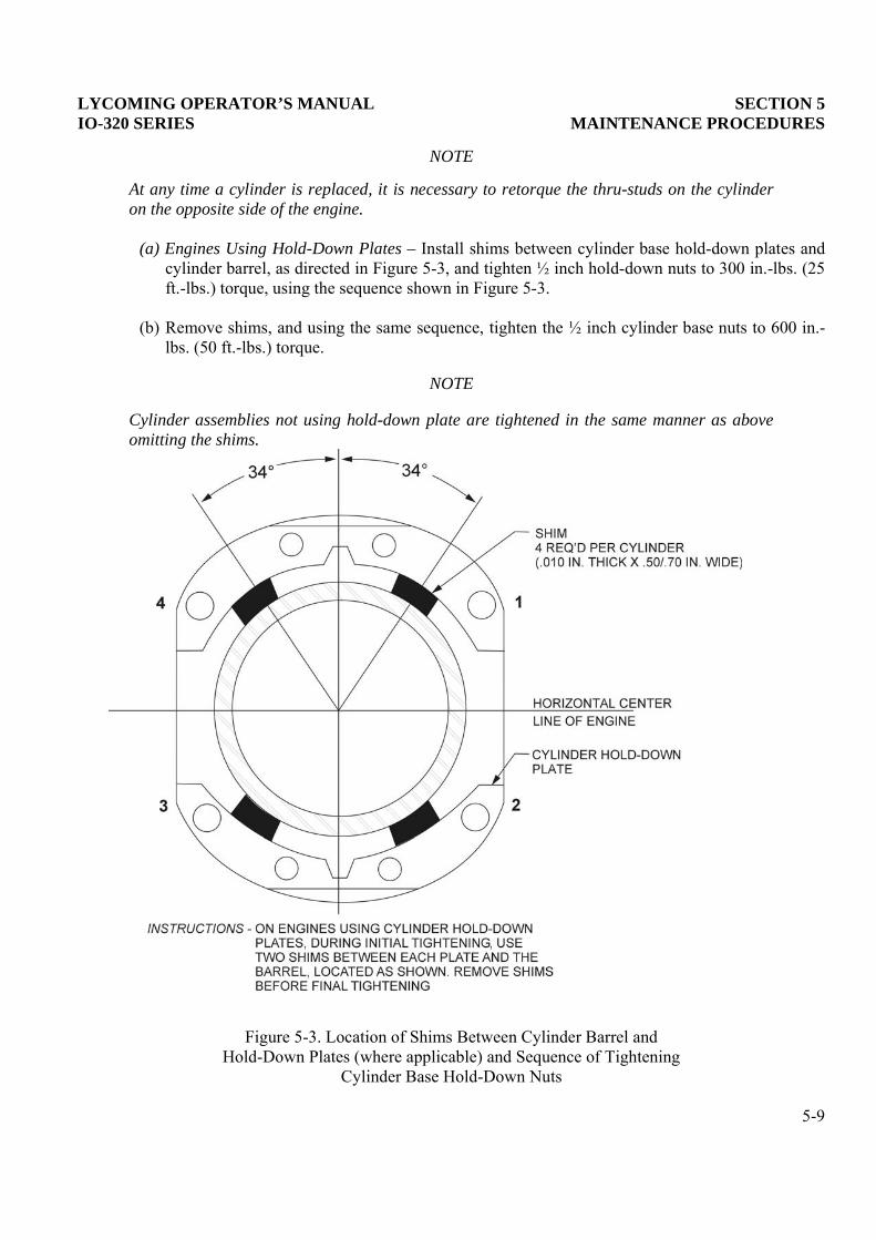
LYCOMING OPERATOR’S MANUAL SECTION 5IO-320 SERIES MAINTENANCE PROCEDURES
NOTE
At any time a cylinder is replaced, it is necessary to retorque the thru-studs on the cylinderon the opposite side of the engine.
(a) Engines Using Hold-Down Plates – Install shims between cylinder base hold-down plates andcylinder barrel, as directed in Figure 5-3, and tighten ½ inch hold-down nuts to 300 in.-lbs. (25ft.-lbs.) torque, using the sequence shown in Figure 5-3.
(b) Remove shims, and using the same sequence, tighten the ½ inch cylinder base nuts to 600 in.-lbs. (50 ft.-lbs.) torque.
NOTE
Cylinder assemblies not using hold-down plate are tightened in the same manner as aboveomitting the shims.
Figure 5-3. Location of Shims Between Cylinder Barrel andHold-Down Plates (where applicable) and Sequence of Tightening
Cylinder Base Hold-Down Nuts
5-9

SECTION 5 LYCOMING OPERATOR’S MANUALMAINTENANCE PROCEDRUES IO-320 SERIES
(c) Tighten the inch hold-down nuts to 300 in.-lbs. (25 ft.-lbs.) torque. Sequence of tightening isoptional.
(d) As a final check, hold the torque wrench on each nut for about five seconds. If the nut does notturn, it may be presumed to be tightened to correct torque.
CAUTION
AFTER ALL CYLINDER BASE NUTS HAVE BEEN TIGHTENED, REMOVE ANY NICKS INTHE CYLINDER FINS BY FILING OR BURRING.
(6) Install a new shroud tube oil seal on the crankcase end of each shroud tube and fit a new annularring in the groove provided in the rocker box and of each shroud tube. Install each shroud tubethrough rocker box and seat the end firmly in the crankcase. Place a spacer, two springs, a lockplate and nut over the stud provided in the rocker box and secure both shroud tubes in place. Bendthe tang of the lock plate to prevent the nut and spring from loosening.
(7) Assemble each push rod in its respective shroud tube, and assemble each rocker in its respectiveposition by placing rocker between bosses and sliding valve rocker shaft in place to retain rocker.Before installing exhaust valve rocker, place rotator cap over end of exhaust valve stem.
(8) Be sure that the piston is at top center of compression stroke and that both valves are closed.Check clearance between the valve stem tip and the valve rocker. In order to check this clearance,place the thumb of one hand on the valve rocker directly over the end of the push rod and pushdown so as to compress the hydraulic tappet spring. While holding the spring compressed, thevalve clearance should be between .028 and .080 inch. If clearance does not come within theselimits, remove the push rod and insert a longer or shorter push rod, as required, to correctclearance.
NOTE
Inserting a longer push rod will decrease the valve clearance.
(9) Install intercylinder baffles, rocker box covers, intake pipes, rocker box drain tubes and exhaustmanifold.
5. GENERATOR OR ALTERNATOR DRIVE BELT TENSION.
Check the tension of a new belt 25 hours after installation. Refer to latest revision of Service InstructionNo. 1129 for methods of checking generator or alternator drive belt tension.
5-10

LYCOMING OPERATOR’S MANUAL
SECTION 6TROUBLE-SHOOTING
Page
Failure of Engine to Start............................................................................................................................ 6-1
Failure of Engine to Idle Properly.............................................................................................................. 6-2
Low Power and Uneven Running............................................................................................................... 6-2
Failure of Engine to Develop Full Power................................................................................................... 6-3
Rough Engine ............................................................................................................................................... 6-3
Low Oil Pressure.......................................................................................................................................... 6-3
High Oil Temperature ................................................................................................................................. 6-3
Excessive Oil Consumption......................................................................................................................... 6-4

This Page Intentionally Left Blank.

LYCOMING OPERATOR’S MANUAL SECTION 6IO-320 SERIES TROUBLE-SHOOTING
SECTION 6
TROUBLE-SHOOTING
Experience has proven that the best method of trouble-shooting is to decide on the various causes of thegiven trouble and then to eliminate causes one by one, beginning with the most probable. The followingcharts list some of the more common troubles, which may be encountered in maintaining engines; theirprobable causes and remedies.
1. TROUBLE-SHOOTING – ENGINE.
TROUBLE PROBABLE CAUSE REMEDY
Failure of Engine to Start Lack of fuel Check fuel system for leaks. Fillfuel tank. Clean dirty lines,strainers or fuel valves.
cranking for a few seconds. Turnignition switch on and proceed tostart in a normal manner.
Defective spark plugs Clean and adjust or replace sparkplugs.
Defective ignition wire Check with electric tester, andreplace any defective wires.
Defective battery Replace with charged battery.
Improper operation of magnetobreaker
Clean points. Check internaltiming of magnetos.
Lack of sufficient fuel flow Disconnect fuel line and checkfuel flow.
Water in fuel injector Drain fuel injector and fuel lines.
Internal failure Check oil screens for metalparticles. If found, completeoverhaul of the engine may beindicated.
6-1

SECTION 6 LYCOMING OPERATOR’S MANUALTROUBLE-SHOOTING IO-320 SERIES
TROUBLE PROBABLE CAUSE REMEDY
Failure of Engine to Idle Properly Incorrect idle mixture Adjust mixture.
Leak in induction system Tighten all connections in theinduction system. Replace anyparts that are defective.
Incorrect idle adjustment Adjust throttle stop to obtaincorrect idle.
Uneven cylinder compression Check condition of piston ringsand valve seats.
Faulty ignition system Check entire ignition system.
Insufficient fuel pressure Adjust fuel pressure.
Low Power and Uneven Running Mixture too rich indicated bysluggish operation, red exhaustflame at night. Extreme casesindicated by black smoke fromexhaust.
Readjustment of fuel injector byauthorized personnel is indicated.
Mixture too lean; indicated byoverheating or backfiring.
Check fuel lines for dirt or otherrestrictions. Readjustment of fuelinjector by authorized personnel isindicated.
Leaks in induction system Tighten all connections. Replacedefective parts.
Defective spark plugs Clean and gap or replace sparkplugs.
Improper fuel Fill tank with fuel ofrecommended grade.
Magneto breaker points notworking properly
Clean points. Check internaltiming of magnetos.
Defective ignition wire Check wire with electric tester.Replace defective wire.
Defective spark plug terminalconnectors.
Replace connectors on spark plugwire.
6-2
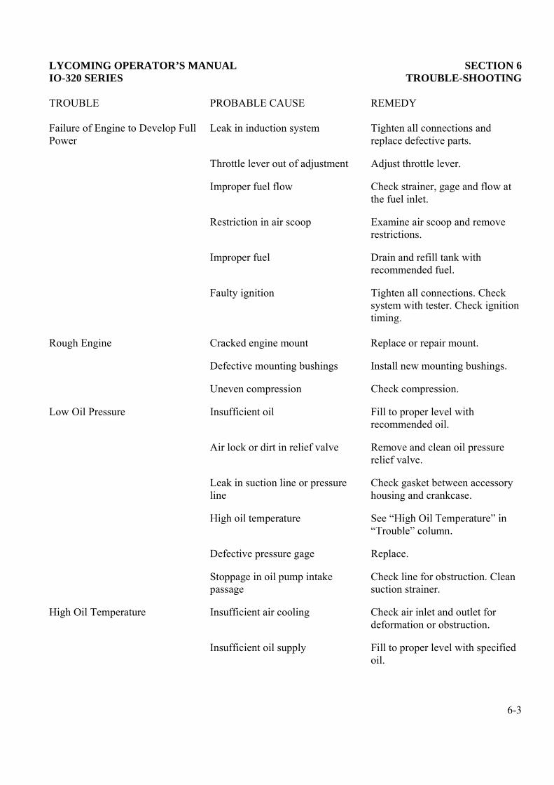
LYCOMING OPERATOR’S MANUAL SECTION 6IO-320 SERIES TROUBLE-SHOOTING
TROUBLE PROBABLE CAUSE REMEDY
Failure of Engine to Develop FullPower
Leak in induction system Tighten all connections andreplace defective parts.
Throttle lever out of adjustment Adjust throttle lever.
Improper fuel flow Check strainer, gage and flow atthe fuel inlet.
Restriction in air scoop Examine air scoop and removerestrictions.
Improper fuel Drain and refill tank withrecommended fuel.
Faulty ignition Tighten all connections. Checksystem with tester. Check ignitiontiming.
Rough Engine Cracked engine mount Replace or repair mount.
Defective mounting bushings Install new mounting bushings.
Uneven compression Check compression.
Low Oil Pressure Insufficient oil Fill to proper level withrecommended oil.
Air lock or dirt in relief valve Remove and clean oil pressurerelief valve.
Leak in suction line or pressureline
Check gasket between accessoryhousing and crankcase.
Defective pressure gage Replace.
Stoppage in oil pump intakepassage
Check line for obstruction. Cleansuction strainer.
High Oil Temperature Insufficient air cooling Check air inlet and outlet fordeformation or obstruction.
Insufficient oil supply Fill to proper level with specifiedoil.
6-3

SECTION 6 LYCOMING OPERATOR’S MANUALTROUBLE-SHOOTING IO-320 SERIES
TROUBLE PROBABLE CAUSE REMEDY
High Oil Temperature (Cont.) Low grade of oil Replace with oil conforming tospecifications.
Clogged oil lines or strainers Remove and clean oil strainers.
Excessive blow-by Usually caused by worn or stuckrings.
Failing or failed bearings Examine sump for metal particles.If found, overhaul of engine isindicated.
Defective temperature gage Replace gage.
Excessive Oil Consumption Low grade of oil Fill tank with oil conforming tospecifications.
Failing or failed bearings Check sump for metal particles.
Worn piston rings Install new rings.
Incorrect installation of pistonrings
Install new rings.
Failure of rings to seat (newnitrided cylinders)
Use mineral base oil. Climb tocruise altitude at full power andoperate at 75% cruise powersetting until oil consumptionstabilizes.
6-4

LYCOMING OPERATOR’S MANUAL
SECTION 7INSTALLATION AND STORAGE
Page
Preparation of Engine for Installation....................................................................................................... 7-1
General.......................................................................................................................................................... 7-1
Inspection of Engine Mounting .................................................................................................................. 7-1
Attaching Engine to Mounts ....................................................................................................................... 7-1
Oil and Fuel Line Connections ................................................................................................................... 7-1
Propeller Installation ................................................................................................................................... 7-1
Preparation of Fuel Injectors for Installation ........................................................................................... 7-2

This Page Intentionally Left Blank.

LYCOMING OPERATOR’S MANUAL SECTION 7IO-320 SERIES INSTALLATION AND STORAGE
SECTION 7
INSTALLATION AND STORAGE
1. PREPARATION OF ENGINE FOR INSTALLATION. Before installing an engine that has been preparedfor storage, remove all dehydrator plugs, bags of desiccant and preservative oil from the engine.Preservative oil can be removed by removing the bottom spark plugs and turning the crankshaft three orfour revolutions by hand. The preservative oil will then drain through the spark plug holes. Draining will befacilitated if the engine is tilted from side to side during the above operation. Preservative oil which hasaccumulated in the sump can be drained by removing the oil sump plug. Engines that have been stored in acold place should be removed to an environment of at least 70°F (21°C) for a period of 24 hours beforepreservative oil is drained from the cylinders. If this is not possible, heat the cylinders with heat lampsbefore attempting to drain the engine.
After the sump has been drained, the plug should be replaced and safety-wired. Fill the sump withlubricating oil. The crankshaft should again be turned several revolutions to saturate the interior of theengine with the clean oil. When installing spark plugs, make sure that they are clean, if not, wash them inclean petroleum solvent. Of course, there will be a small amount of preservative oil remaining in the engine,but this can cause no harm. However, after twenty-five hours of operation, the lubricating oil should bedrained while the engine is hot. This will remove any residual preservative oil that may have been present.
CAUTION
DO NOT ROTATE THE CRANKSHAFT OF AN ENGINE CONTAINING PRESERVATIVEOIL BEFORE REMOVING THE SPARK PLGUS, BECAUSE IF THE CYLINDERSCONTAIN ANY APPRECIABLE AMOUNT OF THE MIXTURE, THE RESULTINGACTION, KNOWN AS HYDRAULICING, WILL CAUSE DAMAGE TO THE ENGINE.ALSO, ANY CONTACT OF THE RPESERVATIVE OIL WITH THE PAINTED SURFACESSHOULD BE AVOIDED.
General , containing crystals of silica-gel or similar material, be brokenduring their term of storage or upon their removal from the engine, and if any of the contents should fall intothe engine, that portion of the engine must be disassembled and thoroughly cleaned before using the engine.The oil strainers should be removed and cleaned in gasoline or some other hydrocarbon solvent. The fueldrain screen located in the fuel inlet of the fuel injector should also be removed and cleaned in hydrocarbonsolvent. The operator should also note if any valves are sticking. If they are, this condition can be eliminatedby coating the valve stem generously with a mixture of gasoline and lubricating oil.
Inspection of Engine Mounting engine has been removed, make surethat the engine mount is not bent or damaged by distortion or misalignment as this can produce abnormalstresses within the engine.
Attaching Engine to Mounts – endations for method of mounting theengine.
Oil and Fuel Line Connections – The oil and fuel line connections are called out in the accompanyinginstallation drawings.
Propeller Installation – Consult the airframe manufacturer for information relative to propeller installation.
7-1

SECTION 7 LYCOMING OPERATOR’S MANUALINSTALLATION AND STORAGE IO-320 SERIES
2. PREPARATION OF FUEL INJECTORS FOR STORAGE.
Fuel injectors that have been prepared for storage should undergo the following procedures before beingplaced in service.
Remove and clean the fuel inlet strainer assembly and reinstall. Inject clean fuel into the fuel inletconnection with the fuel outlet uncapped until clean fuel flows from the outlets. Do not exceed 15 psi inletpressure.
3. PREPARATION OF ENGINE FOR STORAGE OR SHIPMENT.
General cation to installed engines, which are beingremoved from aircraft and will provide protection from corrosion for a period of 30 to 60 days.
Preservation Run from the aircraft, the engine should be givena preservation run under the following operating conditions.
Fuel
Oil
Duration of Run minutes, holding the engine speed to a maximumof 1800 RPM. All precautions pertaining to ground running should be carefully observed. Cylinder head,ignition harness, and magneto temperatures should not be allowed to exceed the prescribed limits.
Compound Injection n the preservative oil from the engineand remove, clean and replace the oil suction and oil pressure screens. Perform any of the engine checks,such as valve clearance or ignition timing, which require rotation of the crankshaft. Disconnect the ignitionharness and remove the spark plugs. Starting with cylinder no. 1, make certain piston is at the bottom ofcompression stroke. Fill cylinder with preservative oil (use same oil as specified for preservation run) androtate crankshaft until piston is at top center. Oil will spill out of spark plug hole. In order to preserve thetop wall of the cylinder, it will be necessary to either rock the engine, or blow compressed air with very lightpressure into the spark plug hole. Following the engine firing order, preserve the remainder of the cylindersin the same manner. When all cylinders have been treated, then spray the exhaust port and valve of eachcylinder with the piston ¼ turn before top center on the exhaust stroke. When absolutely certain that nofurther need exists for turning the crankshaft, again spray each cylinder through the spark plug holes.(Maintain spray nozzle temperature at 200°F to 200°F (93°C to 104°C) for all spraying operations.)
Installation of Seals and Plugs ycoming P/N 40238 or equivalent) inspark plug holes. Install ignition cable protectors (Lycoming P/N 40239 or equivalent) over the spark plugterminal of each ignition cable and secure by attaching to the end of the dehydrator plug. Flush all accessorydrives for which oil seals are provided with preservative oil before assembling the drive covers. Suitablecovers should be used in sealing the exhaust ports; moisture resistant tape (Minnesota Mining andManufacturing Company, 711 Acetate Fibre Tape or equivalent) will be sufficient for the groundconnections and similar openings. Install a plug (Lycoming P/N 1540 or equivalent) in the thermometer wellat the rear of the oil pressure screen housing. Install sealing caps (Lycoming P/N 61595 or equivalent) overthe breather opening and (Lycoming P/N 61596 or equivalent) over the generator or alternator blast tube.Install tachometer drive cap (Lycoming P/N 61545 or equivalent) over tachometer drive. Make sure all otheropenings are properly sealed.
7-2

LYCOMING OPERATOR’S MANUAL SECTION 7IO-320 SERIES INSTALLATION AND STORAGE
Exterior Surfaces surfaces should be coated with soft filmcorrosion preventative compound (E.F. Houghton and Company, Cosmoline 1059 or equivalent). The starterring gear and propeller mounting surfaces in particular should receive a liberal coating of the compound.
Fuel Injector returned for overhaul, must be flushed withpreserving oil (Specification MIL-O-6081, Grade 1010), using the following procedure.
Remove plugs and drain all fuel oil from the injector. If available, apply 10 to 15 psi air pressure to thefuel inlet, until all fuel is discharged from the injector.
Replace plugs and apply flushing oil filtered through a 10 micron filter at 13 to 15 psi to the fuel inlet untiloil is discharged from the servo line.
Replace fuel inlet plug.
CAUTION
DO NOT EXCEED THE RECOMMENDED AIR PRESSURE AS INTERNAL DAMAGE TOTHE INJECTOR MAY RESULT.
After filling with preservative oil the injector should be protected from dust and dirt, and given suchprotection against moisture as climatic conditions at the point of storage require.
The injector shall be tagged as follows: The fuel chambers and passages of this fuel injector werepreserved with oil conforming to Specification MIL-O-6081, Grade 1010. Before using de-preserve inaccordance with instructions
Shipping Case ngine should be secured in a suitable engineshipping container. The date of preservation and the following legend should be legibly marked on the sideof the container:
“On (Date) the engine was preserved for 60 days short term storage with preservativeoil and cylinder and crankcase dehydrator plugs shall be inspected on arrival at destinationor 30 days after the above date (whichever occurs sooner) to determine of renewal of thedehydrating agent is necessary.”
4. RECOMMENDED PROCEDURE FOR RE-PRESERVATION. The engine shall be examined every 30days (or less, depending on weather and locality). If any evidence of corrosion is present, the affected areashould be cleaned free of corrosion and the engine re-preserved.
Engines prepared in the preceding manner are not adequately protected for extended periods of storage. Ifat the end of 60 days, it is found that the engine must remain in storage for an additional period, the enginemust be re-preserved according to the foregoing procedure.
NOTE
Inspection and re-preservation will not be the responsibility of the engine manufacturer afterengines have been shipped from the engine manufacturer’s plant. It shall be theresponsibility of the consignee to put engines into service in the order of storage preparationdate to reduce the storage period to a minimum
7-3

SECTION 7 LYCOMING OPERATOR’S MANUALINSTALLATION AND STORAGE IO-320 SERIES
Figure 7-1. Fuel Metering System
7-4

LYCOMING OPERATOR’S MANUAL SECTION 7IO-320 SERIES INSTALLATION AND STORAGE
Figure 7-2. Fuel Injector
7-5

SECTION 7 LYCOMING OPERATOR’S MANUALINSTALLATION AND STORAGE IO-320 SERIES
Figure 7-3. Magneto Connections
7-6

LYCOMING OPERATOR’S MANUAL SECTION 7IO-320 SERIES INSTALLATION AND STORAGE
Figure 7-4. Optional Oil Cooler Connections
7-7

SECTION 7 LYCOMING OPERATOR’S MANUALINSTALLATION AND STORAGE IO-320 SERIES
Figure 7-5. Installation Draw Typical IO-320-B Series
7-8

LYCOMING OPERATOR’S MANUAL SECTION 7IO-320 SERIES INSTALLATION AND STORAGE
7-9
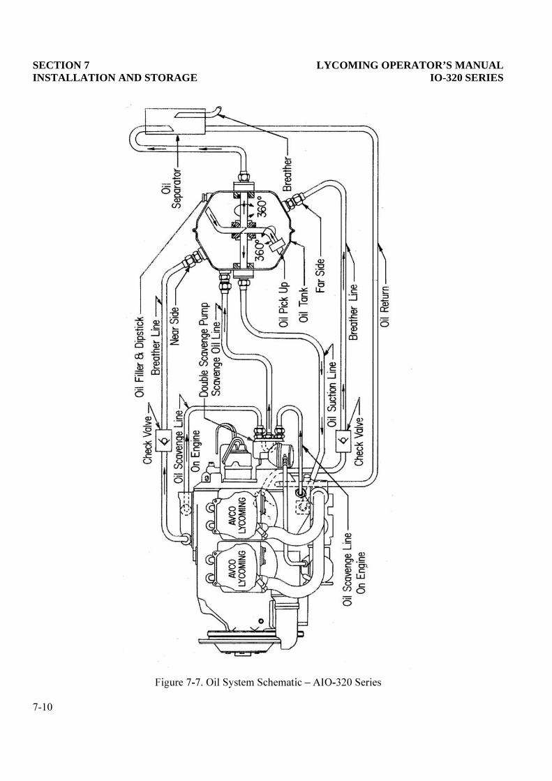
SECTION 7 LYCOMING OPERATOR’S MANUALINSTALLATION AND STORAGE IO-320 SERIES
7-10

LYCOMING OPERATOR’S MANUAL
SECTION 8TABLES
Page
Table of Limits ............................................................................................................................................. 8-1
Ground Run After Top Overhaul .............................................................................................................. 8-2
Flight Test After Top Overhaul.................................................................................................................. 8-3
Full Throttle HP at Altitude........................................................................................................................ 8-4
Table of Speed Equivalents ......................................................................................................................... 8-4
Centigrade-Fahrenheit Conversion Table................................................................................................. 8-5
Inch-Fraction Conversions.......................................................................................................................... 8-6

This Page Intentionally Left Blank.

LYCOMING OPERATOR’S MANUAL SECTION 8IO-320 SERIES TABLES
SECTION 8
TABLES
FOR TIGHTENING TORQUE RECOMMENDATIONS AND INFORMATION
CONCERNING TOLERLANCES AND DIMENSIONS THAT MUST BE MAINTAINED
IN LYCOMING AIRCRAFT ENGINES, CONSULT LATEST REVISION OF SPECIAL
SERVICE PUBLICATION NO. SSP-1776.
CONSULT LATEST REVISION OF SERVICE INSTRUCTION NO. 1029 AND NO.
1150 FOR INFORMATION PRETINENT TO CORRECTLY INSTALLING CYLINDER
ASSEMBLY.
8-1

SECTION 8 LYCOMING OPERATOR’S MANUALTABLES IO-320 SERIES
8-2
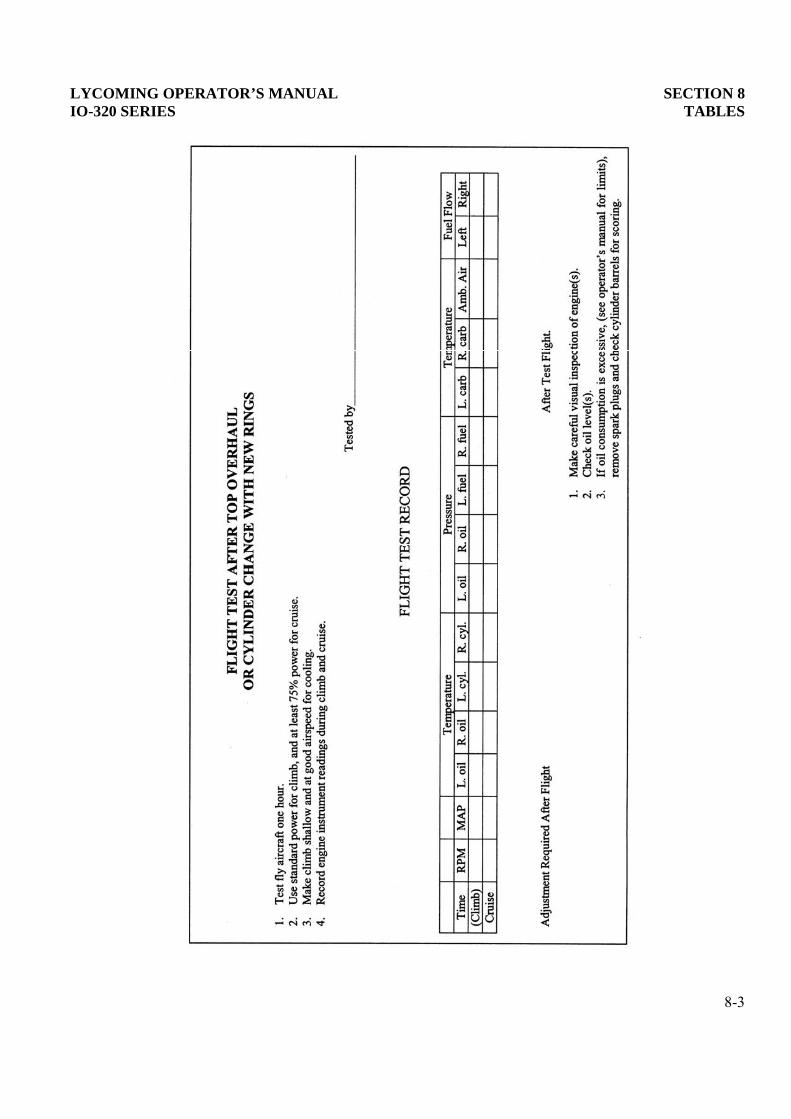
LYCOMING OPERATOR’S MANUAL SECTION 8IO-320 SERIES TABLES
8-3

SECTION 8 LYCOMING OPERATOR’S MANUALTABLES IO-320 SERIES
FULL THROTTLE HP AT ALTITUDE(Normally Aspirated Engines)
AltitudeFt.
% S.L.H.P.
AltitudeFt.
% S.L.H.P.
AltitudeFt.
% S.L.H.P.
0 100 10,000 70.8 19,500 49.1500 98.5 11,000 68.3 20,000 48.0
1,000 96.8 12,000 65.8 20,500 47.62,000 93.6 13,000 63.4 21,000 46.02,500 92.0 14,000 61.0 21,500 45.23,000 90.5 15,000 58.7 22,000 44.04,000 87.5 16,000 56.5 22,500 43.35,000 84.6 17,000 54.3 23,000 42.26,000 81.7 17,500 53.1 23,500 41.47,000 78.9 18,000 52.1 24,000 40.38,000 76.2 18,500 51.4 24,500 39.59,000 73.5 19,000 50.0 25,000 38.5
TABLE OF SPEED EQUIVALENTS
Sec./Mi. M.P.H. Sec./Mi. M.P.H. Sec./Mi. M.P.H.
72.0 50 24.0 150 14.4 25060.0 60 22.5 160 13.8 26051.4 70 21.2 170 13.3 27045.0 80 20.0 180 12.8 28040.0 90 18.9 190 12.4 29036.0 100 18.0 200 12.0 30032.7 110 17.1 210 11.6 31030.0 120 16.4 220 11.2 32027.7 130 15.6 230 10.9 33025.7 140 15.0 240 10.6 340
8-4

LYCOMING OPERATOR’S MANUAL SECTION 8IO-320 SERIES TABLES
CENTIGRADE-FAHRENHEIT CONVERSION TABLE
Example: To convert 20°C to Fahrenheit, find 20 in the center column headed (F-C); then read 68.0°F inthe column (F) to the right. To convert 20°F to Centigrade; find 20 in the center column and read -6.67°C inthe (C) column to the left.
C F-C F C F-C F
-56.7 -70 -94.0 104.44 220 428.0-51.1 -60 -76.0 110.00 230 446.0-45.6 -50 -58.0 115.56 240 464.0-40.0 -40 -40.0 121.11 250 482.0-34.0 -30 -22.0 126.67 260 500.0-28.9 -20 -4.0 132.22 270 518.0-23.3 -10 14.0 137.78 280 536.0-17.8 0 32.0 143.33 290 554.0
-12.22 10 50.0 148.89 300 572.0-6.67 20 68.0 154.44 310 590.0-1.11 30 86.0 160.00 320 608.04.44 40 104.0 165.56 330 626.0
10.00 50 122.0 171.11 340 644.015.56 60 140.0 176.67 350 662.021.11 70 158.0 182.22 360 680.026.67 80 176.0 187.78 370 698.032.22 90 194.0 193.33 380 716.037.78 100 212.0 198.89 390 734.043.33 110 230.0 204.44 400 752.048.89 120 248.0 210.00 410 770.054.44 130 266.0 215.56 420 788.060.00 140 284.0 221.11 430 806.065.56 150 302.0 226.67 440 824.071.00 160 320.0 232.22 450 842.076.67 170 338.0 237.70 460 860.082.22 180 356.0 243.33 470 878.087.78 190 374.0 248.89 480 896.093.33 200 392.0 254.44 490 914.098.89 210 410.0 260.00 500 932.0
8-5

SECTION 8 LYCOMING OPERATOR’S MANUALTABLES IO-320 SERIES
INCH FRACTIONS CONVERSIONSDecimals, Area of Circles and Millimeters
InchFraction
DecimalEquiv.
AreaSq. In.
MMEquiv.
InchFraction
DecimalEquiv.
AreaSq. In.
MMEquiv.
1/64 .0156 .0002 .397 1/2 .5 .1964 12.7001/32 .0312 .0008 .794 17/32 .5312 .2217 13.4943/64 .0469 .0017 1.191 35/64 .5469 .2349 13.891
1/16 .0625 .0031 1.587 9/16 .5625 .2485 14.2883/32 .0937 .0069 2.381 19/32 .5937 .2769 15.081
7/64 .1094 .0094 2.778 39/64 .6094 .2916 15.4781/8 .125 .0123 3.175 5/8 .625 .3068 15.875
5/32 .1562 .0192 3.969 21/32 .6562 .3382 16.66911/64 .1719 .0232 4.366 43/64 .6719 .3545 17.0653/16 .1875 .0276 4.762 11/16 .6875 .3712 17.4627/32 .2187 .0376 5.556 23/32 .7187 .4057 18.256
15/64 .2344 .0431 5.593 47/64 .7344 .4235 18.6531/4 .25 .0491 6.350 3/4 .75 .4418 19.050
9/32 .2812 .0621 7.144 25/32 .7812 .4794 19.84419/64 .2969 .0692 7.540 51/64 .7969 .4987 20.241
5/16 .3125 .0767 7.937 13/16 .8125 .5185 20.63711/32 .3437 .0928 8.731 27/32 .8437 .5591 21.431
23/64 .3594 .1014 9.128 55/64 .8594 .5800 21.8283/8 .375 .1105 9.525 7/8 .875 .6013 22.225
13/32 .4062 .1296 10.319 29/32 .9062 .6450 23.01927/64 .4219 .1398 10.716 59/64 .9219 .6675 23.4167/16 .4375 .1503 11.112 15/16 .9375 .6903 23.81215/32 .4687 .1725 11.906 31/32 .9687 .7371 24.60631.64 .4844 .1842 12.303 63/64 .9488 .7610 25.003
8-6