NOS. 90-390C, 94-321C FILED: February 23, 1998 …...and that many of those cycles were...
49
NOS. 90-390C, 94-321C FILED: February 23, 1998 GEOFFREY T. KEATING , McKenna & Cuneo, L.L.P., Washington, D.C., with whom was Daryle A. Jordan , attorneys of record for plaintiff. SHALOM BRILLIANT , Commercial Litigation Branch, Civil Division, Department of Justice, Washington, D.C., with whom were David M. Cohen , Director and Frank W. Hunger , Assistant Attorney General, attorneys of record for the defendant. Joseph G. Councill, Jr. , Army Corps of Engineers, of counsel. O P I N I O N HORN, Judge . BACKGROUND * * * * * * * * * * * * * * * * * * * * * * * * * * * * * M.A. MORTENSON COMPANY, * a Minnesota Corporation, * * Plaintiff, * * Government Contracts; Latent v. * Defect; Defective Specifications; * Fed. R. Evid. 407. THE UNITED STATES, * * Defendant. * * * * * * * * * * * * * * * * * * * * * * * * * * * * * * * *
Transcript of NOS. 90-390C, 94-321C FILED: February 23, 1998 …...and that many of those cycles were...

NOS. 90-390C, 94-321C
FILED: February 23, 1998
GEOFFREY T. KEATING, McKenna & Cuneo, L.L.P., Washington, D.C., with whom was Daryle A. Jordan, attorneys of record for plaintiff.
SHALOM BRILLIANT, Commercial Litigation Branch, Civil Division, Department of Justice, Washington, D.C., with whom were David M. Cohen, Director and Frank W. Hunger, Assistant Attorney General, attorneys of record for the defendant. Joseph G. Councill, Jr., Army Corps of Engineers, of counsel.
O P I N I O N
HORN, Judge.
BACKGROUND
* * * * * * * * * * * * * * * * * * * * * * * * * * * **
M.A. MORTENSON COMPANY, *a Minnesota Corporation, *
*Plaintiff, *
* Government Contracts; Latentv. * Defect; Defective Specifications;
* Fed. R. Evid. 407.THE UNITED STATES, *
*Defendant. *
***
* * * * * * * * * * * * * * * * * * * * * * * * * * * *
This case comes before the court following a contracting officer's final decision dated July 31, 1989, finding plaintiff responsible for costs incurred by the government in the amount of $48,873.32 for repairs to the 90 Row fuel line of the B-1B support facilities' hydrant fueling system at issue, which is included in Count I of the complaint filed in this court, and following a contracting officer's final decision dated April 9, 1990, denying plaintiff's claim in the amount of $325,114.00 for repairs to the 70 Row fuel line of the same system, which is included in Count II of the complaint filed in this court.(1) These two counts are included in a complaint which was filed in a case docketed as Case No. 90-390C. Plaintiff's motion to add Bristol Metals, Inc., the manufacturer of the pipe, as a third-party defendant was denied on January 9, 1992.
On August 13, 1993, the court issued an opinion, published at 29 Fed. Cl. 82 (1993), denying (1) defendant's motion to dismiss Count II (the $325,114.00 claim) for lack of jurisdiction premised upon an allegedly defective Contract Disputes Act certification, and (2) both defendant's motion and plaintiff's cross-motion for summary judgment on Counts I and II. The court found that genuine issues of material fact remained in dispute.
Subsequently, the plaintiff filed a second complaint, in a case docketed as Case No. 94-321C, challenging a government decision issued February 11, 1994, that found plaintiff liable to the defendant for the cost of redesigning and replacing the hydrant fueling system.(2) The government filed a counterclaim, to plaintiff's second complaint, for costs associated with the replacement of the hydrant fuel system in the amount of $6,136,574.00. On June 15, 1994, these two cases, Nos. 90-390C and 94-321C were consolidated pursuant to the court's order. A trial on liability was conducted, after which the parties filed post-trial pleadings.
FACTS
The United States Army Corps of Engineers, Omaha District, awarded Contract No. DACA45-85-C-0099 (the "contract") to M.A. Mortenson Company ("Mortenson"), on March 19, 1985, pursuant to an advertised invitation for bids, for a price of $27,437,200.00. The contract required the construction of B-1B Support Facilities, Phase I, Package II, at Ellsworth Air Force Base, South Dakota, including, among other things, the installation of a hydrant fueling system, in accordance with specifications prepared by the government. The hydrant fueling system consists of a series of three rows of pipe, referred to as the 70, 80 and 90 Rows, extending from a pump house to the aircraft parking aprons on the airfield where hydrant fueling pits are located. Each row has from six to nine fuel pits.
Plaintiff, Mortenson, subcontracted the mechanical work, including the pipe installation to Natkin & Co. ("Natkin"). The pipe prescribed for this hydrant fuel system in specification Section 15R of the contract was the ASTM A312, schedule 10S, grade 304L, stainless steel pipe, intended for high-temperature and general corrosive service. This pipe was to conform to American Society for Testing & Materials ("ASTM") specifications as printed.(3) Natkin supplied welded stainless steel pipe manufactured by Bristol Metals, Inc. ("Bristol"). The government believed at the time of delivery that the pipe conformed to ASTM A312 standard specifications. The pipe was accepted and installed. After the Corps of Engineers accepted the hydrant fuel system, in April 1987, the Air Force used the new system for more than a year without detecting any leaks.
American National Standards Institute ("ANSI") Standard B31.3, as prepared under the auspices of the American Society of Mechanical Engineers ("ASME"), is an American national code for pressure piping and "sets forth engineering requirements deemed necessary for safe design and construction of piping systems." The ANSI Standard B31.3 introduction states "[t]he designer is cautioned that the Code is not a design handbook. The Code does not do away with the need for the designer or competent engineering
judgment." The hydrant fueling piping system for Ellsworth Airforce Base was designed under ANSI Standard B31.3 on "Chemical Plant and Petroleum Refinery Piping." This standard or code for pressure piping is incorporated into the contract by direct reference in Section 15R, paragraph 1, "APPLICABLE PUBLICATIONS." Chapter I of the ANSI Standard B31.3 defines the scope of the responsibility of the various entities in any piping construction endeavor:
300 GENERAL STATEMENTS * * *
(b) Responsibilities
(1) Owner. The owner of a piping system shall have overall responsibility for compliance with this Code, and for establishing the requirements for design, construction, examination, inspection, and testing which will govern the entire fluid handling or process system of which piping is a part. The owner is responsible for identifying those fluid services. . . .
(2) Designer. The designer is responsible to the owner for assurance that the engineering design of piping complies with the requirements of this Code and with any additional requirements established by the owner.
(3) Manufacturer, Fabricator, and Erector. The manufacturer, fabricator, and erector of piping are responsible for providing materials, components, and workmanship in compliance with the requirements of this Code and of the engineering design.
Chapter II, the design chapter of ANSI B31.3, specifically addresses the conditions and criteria of the piping system design parameters:
301.2 Design Pressure
The design pressure of a piping system shall be not less than the pressure at the most severe condition of coincident internal or external pressure and temperature (minimum or maximum) expected during service, except as provided in 302.2.4. . . . The most severe condition is that which results in the greatest required component thickness and the highest component rating.
* * *
302.2.4 Allowances for Pressure and Temperature Variations, Metallic Piping. Occasional variations of pressure or temperature, or both, above operating levels are characteristic of certain services. The most severe conditions of coincident pressure and temperature during the variation shall be used to determine the design conditions unless all of the following criteria are met.
* * *
(d) The number of cycles (or variations) shall not exceed 7,000 during the life of the piping system.
(e) In no case shall the increased pressure exceed the test pressure used . . . for the piping system. * * *
(g) The combined effects of the sustained and cyclic variations on the serviceability of all components in the system have been evaluated.
Moreover, this chapter of the ANSI code sets forth design condition concerns regarding cyclic loading:
301.10 Cyclic Effects
Fatigue due to pressure cycling, thermal cycling, and other cyclic loading shall be considered in the design of piping.
In what is referred to by the parties as the CERL Report (CERL stands for Construction Engineering Research Laboratory of the Army Corps of Engineers), the following words articulate the nexus between the source of cyclic loading and the facts of the instant case:
Fatigue is associated with cyclic loading; that is, changes in stress levels during operation. In the case of the hydrant fueling systems, these stresses are associated with pressure excursions which result when valves are periodically opened and closed during aircraft fueling operations.
The ANSI Standard B31.3 addresses these concerns by specifically delineating the pipe that may be used in paragraph 305.2.3, entitled "Pipe for Severe Cyclic Conditions." The ANSI piping code does not allow the use of A312 welded seam pipe for severe cyclic loading conditions, instead specifying that only seamless ASTM A312 pipe is permitted for severe cyclic loading.(4)
The parties have stipulated that neither the Air Force nor the Corps of Engineers performed a fatigue analysis of the hydrant fueling system in the design of that system. In addition, the hydrant fueling system was not designed for a cyclic loading condition, or to accommodate the cyclic loading duty of the system. Dr. Allen Selz, plaintiff's expert in design, failure analysis and fatigue, and a member of a number of professional societies, including the ASME's Subcommittee on Inspection Methods, engaged in the following colloquy at trial with regard to his review of the Ellsworth hydrant fueling system design:
A I saw no calculations that took into account the repetitive cyclic loading or repetitive surge loadings or cyclic loading. I did see a calculation made using an American Waterworks Association specification that calculated surge pressures and determined that they were acceptable as occasional loads. I don't agree with that calculation. . . . Because the -- stresses that were produced exceeded the allowable stresses and, I mean, even in B-31.3. . . . I know of nothing that looked at so-called cumulative damage, so-called fatigue evaluation.
Q Is it your opinion that a so-called fatigue evaluation should have been made in the design of this project?
A Definitely, yes.
Q Dr. Selz, let me ask you this. Fatigue can only occur in pipes subjected to cycling pressures of cyclic loading; isn't that right?
A Fluctuating or cyclic fluctuating, yes. Changing loads.
The parties have stipulated, however, that cyclic loading is normal to the everyday operation of the hydrant fueling system at Ellsworth Air Force Base. In other words, according to Dr. Selz, the system was designed as a static system, was not designed to withstand cyclic loading and was not designed with adequate fatigue design evaluation.
The system, however, once studied by the defendant's engineers after the leaks were identified was estimated to have 30,000 cycles a year which extrapolates to 600,000 cycles over a twenty-year period
and that many of those cycles were significantly in excess of 182 psi. Dr. Darrell Socie, defendant's expert in metallurgy, failure analysis and durability analysis, testified that there were "hundreds of cycles in the 200 psi range" over the course of a year and a half, but he testified that he believed that these were within the design criteria for this system. Plaintiff's expert in design, failure analysis and fatigue, Dr. Selz, articulated on direct examination that the critical pressure amount for design purposes was 182 psi and carefully demonstrated how this figure was ascertained:
Now, back to design pressure for a moment. Dr. Socie I think talked about a design pressure of 250 or 275 psi, but wasn't really able to cite a reference for that. I fo[u]nd none in all my work on this program trying to find a specified design pressure.
* * *
The only way you can determine a design pressure by anything that I found is that B31.3 says that the design pressure shall in no case be -- let me state it just right. The test pressure shall be at least 110 percent of the design pressure.
Now, there was a test imposed on this piping system, and it was 200 psi. That means that the maximum that the design pressure in default of any other definition had to be 200 divided 1.1 or 182 psi.
Certainly there were, by Dr. Socie's own measurements, many, many cycles in excess of 182 psi.
The ANSI B31.3 specifically states that "the number of cycles (or variations) shall not exceed 7,000 during the life of the piping system" a figure which equates to between two and three cycles a day for twenty years. Moreover, the parties are in agreement that the cyclic loading condition imposed upon the hydrant fueling system was among the factors that caused the ruptures in sections of piping and caused the leaks in the system.
It is apparent from the testimony of John Paul Soukup, a Natkin vice president and district manager from the Omaha District, and William G. Anderson, a Natkin project manager, that the mechanical subcontractor did not undertake the design of piping systems or hydrant fueling systems; instead they assumed that the designer had incorporated requirements to meet specific conditions into the design and that the subcontractor simply installs the systems according to the particular contract specifications. The testimony of Mr. Anderson on direct examination indicates that Natkin relied upon the designer of the project for its hydrant fueling system design knowledge:
Q With respect to the manner of operation of the pumping system, when did you learn that?
A That was part of the contract specifications that were provided to us, a description of the sequence of operation was included in the contract documents.
Q If I used the [terms] cyclic loading or cyclic conditions, do you know what that means generally?
A I have a general knowledge of it, yes.
Q Did you have a general knowledge of that term at the time that the hydrant fuel system was installed?
A No.
Q Putting aside the term cyclic loading and cyclic conditions, did you have a knowledge of, or did you understand that the way this pumping system would operate, there would be frequent opening and
closing of valves?
A Yes, I did understand that.
Q Do you know whether that was generally understood in Natkin?
A Yes.
Q At that time, was there a concern in Natkin to your knowledge, on the part of yourself or expressed to you, that the opening and closing of valves might involve some problem in connection with the kind of pipe that was specified?
A No, we assumed the designer had incorporated that in his design.
Additionally, Mr. Anderson further testified that in 1986 with modification 77, the government had knowledge and did attempt to address concerns about pressure surges in the design of the hydrant fueling system:
Q You say there was some concern about [a problem]. Can you be more specific, who expressed that concern?
A Particularly by the information returned to me by Clay Valve about doing modifications to the fuel valves. That this was out of their normal practice or design of the valve, and that it represented a departure from their normal scope of supply for hydrant fuel valves for the Air Force, and that it was, by my understanding, in response to some pressure events anticipated in the system.
Q Did you testify in your direct testimony, that the concern expressed by Clay Valve had to do with that the change might be a cause for some safety problem at the pumping end of the plane?
A Their primary concern expressed to me was that it obviated safe fuel principles for the aircraft and the personnel.
Q Did you testify that the change would involve slowing the speed of the closing of the valves?
A Yes.
Q Did anyone indicate that . . . would have an effect on pressure fluctuations within the system?
A I don't know that it was expressed in that way, but certainly it would have some effect, by my understanding of the system operation.
Q But, as between Clay Valve and Natkin, were there any statements made between those two parties as to any impact on pressure fluctuations within a system from this change?
A Yes, Mr. Roberts, Mr. Vic Roberts of Clay Valve, articulated that to me in correspondence.
Q What concerns did he articulate?
A That the modification of the valves, I believe, was because of some surge analysis of the system, indicating that there were unacceptable pressure levels generated by fast closure of the valves.

Q And --
A And that the Air Force was seeking to attenuate that by modification of the valves rather than applying some other design principle to the system design.
Section 15R of the contract specifications, titled "PIPE, VALVES AND FITTINGS FOR PRESSURIZED HYDRANT FUELING SYSTEM," delineates the pipe material, quality and type to be utilized by the contractor:
3. MATERIALS. No plain steel or zinc-coated metals or brass, bronze, or other copper bearing alloys shall be used in contact with the fuel anywhere in the hydrant fueling system, except plain steel materials shall be used for all piping from and to the operating tanks up to the filter separators in the pumphouse
3.1 PIPE. * * *
3.1.2 Hydrant Fueling System Piping. Aboveground (and buried) piping shall be stainless steel or plain steel as indicated on the drawings.
3.1.3 Stainless Steel Pipe shall conform to ASTM Specification A312, Grade 304L. . . .
Subparagraph 3.1.3, also specifies wall thicknesses for various diameters of stainless steel pipe for the hydrant fueling system, including 0.188 inches for fourteen, sixteen and eighteen inch diameter pipe. The ASTM's Standard Specification A312 likewise specifies 0.188 inches as the nominal or average wall thickness for fourteen, sixteen and eighteen inch diameter pipe.
The ASTM Standard Specification A312 is incorporated into the contract by direct reference in Section 15R, paragraph 1, "APPLICABLE PUBLICATIONS." ASTM A312, which delineates the standard specifications for "seamless and straight-seam welded austenitic steel pipe," provides in turn that the pipe must conform to the requirements of ASTM A530. ASTM Standard Specification A530 states:
11. Permissible Variations in Wall Thickness
11.1 Seamless and Welded (no filler metal added) -- The minimum wall thickness at any point shall not be more than 12.5 % under the nominal wall thickness specified. The minimum wall thickness on inspection is shown in Table XI.
Table XI lists 0.164 inches as the minimum wall thickness on inspection for nominal wall thickness of 0.188 inches. The minimum wall thickness provisions of ASTM A312/A530 apply only to pipe as of the time the pipe was placed in service. Pressure, service, denting or working during installation all may affect the wall thickness of pipe which as manufactured met the minimum wall requirements.
ASTM A312 does not expressly state or specify requirements for the longitudinal weld, weld fusion and weld penetration other than to state in subparagraph 5.2, titled "Manufacture," that "[t]he pipe shall be made by the seamless or an automatic welding process, with no addition of filler metal in the welding operation." In addition, the ASTM Standard Specification A312 incorporated into the contract does not provide express criteria to evaluate partial lack of fusion, nor does it provide an express requirement for weld quality. Defendant's welding expert Kenneth Coryell testified, upon questioning by Mortenson's counsel, that not only did the pipe specifications in the contract fail to specify weld quality, but also that
the supplementary weld quality requirements were available for ASTM A312 and could have been incorporated into the contract specifications:
Q Are you aware, too, sir, that the ASTM A312 requirement or specification standard has no specific requirement for weld depth or penetration?
A Yes. There is no specific language to that effect.
Q Are you aware, sir, that there are some ASTM pipe standards that do make such a specific description of full penetration if that is what they want?
A Yes. In fact, the supplementary requirements to A312 have provision for radiographic quality that includes penetration in those criteria as well.
Q But no such supplementary requirements were required on the Ellsworth pipe contract, were they?
A It is my understanding that they were not. I have no firsthand knowledge of that.
One example of specifications with "supplementary requirements" cited in the joint stipulations is ASTM A358 for electric fusion welded austenitic chromium nickel alloy steel pipe.(5) ASTM A358 provides that the joints shall be full penetration double or single welded butt joints. A358 is welded using filler material which makes the detection of partial lack of fusion by radiography much more reliable. ANSI B31.3 does not prohibit A358 welded pipe for cyclic service.
No additional or supplementary weld requirements were made of the pipe in the contract specifications. The contract specification relating to the hydrant fueling system does not use the term "full penetration of the weld." There were no requirements in ASTM Standard Specification A312 that the pipe weld have full penetration, and therefore, none were incorporated into the contract specifications.
Section 15R of the contract specifications, subparagraph 1.6, lists the American Welding Society ("AWS") A3.0, "Welding Terms and Definitions," among the publications applicable and incorporated by reference into the contract. AWS A3.0 defines "automatic welding" as "[w]elding with equipment which performs the welding operation without adjustment of the controls by a welding operator." In contrast, "machine welding" is defined in the AWS A3.0 as "[w]elding with equipment which performs the welding operation under the constant observation and control of a welding operator." ANSI Standard B31.3 adopts the AWS's definition of "automatic welding" but the definition of "machine welding" is notably absent. Moreover, the ANSI Standard B31.3 definition of "welding operator," as adopted from the AWS, is "[o]ne who operates machine or automatic welding equipment." In turn, a "welder" is defined in the ANSI Standard B31.3 definitions, as adopted from the AWS, as "[o]ne who performs a manual or semi-automatic welding operation." The only example of "semi-automatic welding" in the ANSI and AWS definitions provided by the parties to the court states that: "equipment . . . controls only the filler metal feed. The advance of the welding is manually controlled."(6)
Michael Boling, vice-president of Bristol, testified upon questioning by the government's counsel as to the pipe fabrication and welding technology utilized in the manufacturing of the ASTM A312 pipe Bristol supplied to Natkin and Mortenson:
Q Have you personally observed or participated in the welding of longitudinal seams of stainless steel pipe at this time?

A Yes.
Q And you are familiar with the methods of welding that Bristol Metal was using, is that correct?
A Yes.
Q Had you observed or participated in welding of longitudinal seams of Bristol Metal's pipe during the 1980s?
A Yes.
Q Are you familiar with the pipe that is at issue in this litigation as the pipe supplied by Bristol for use in the Ellsworth Air Force Base hydrant fuel system?
A Yes.
Q And are you familiar with the manufacturing method employed by Bristol in manufacturing that pipe?
A I'm familiar with the manufacturing processes we used to manufacture pipe of that size in nature, not necessarily that pipe in question, but pipe of that size and wall thickness.
* * *
Q . . . Can you describe for me the method and the machinery used at Bristol for welding this kind of pipe?
A Yes. That pipe would have been manufactured on what we call our boom welder. It's a welding device. The pipe is rolled -- the plate is rolled into a cylinder and tack welded along the seam. It lays in a cradle. There's a boom that comes up on the inside with a torch, and there's a fixed torch on the outside of the pipe. The pipe is moved on track horizontally with the inside torch and the outside torch in position and it just moves through between the torches.
Q Can you see the inside torch while the welding process is going on?
A Not without going around and looking up inside the pipe.
Q So it does not glow through the pipe?
A Yes, you can see the red glow of the torch where the torch is with the red spot that shows through.
Q All right. Can you describe the process from the time that the pipe is loaded onto this cradle or this machine until the welding is done. Who does what? Do you have an operator observing or doing anything?
A Yes, there is an operator. The pipe is loaded on the cradle. He sits the torches, strikes the arc on the ID torch first because it travels across the ID torch.
Q The ID torch means?
A Inside diameter. It's a torch inside the pipe first. So it strikes an arc, and approximately seven inches later the OD torch outside the torch strikes an arc on the outside. [The operator] is there to make sure the

arcs are struck and to watch the welding process.
Q Now, when he watches the welding process, what is he watching for?
A Everything. To make sure the machine is working okay. To keep the welding torches on track.
Q How does he keep the welding torches on track?
A He has adjustments to make.
Q Does it ever happen that the welding torches go off track?
A Yes, I'm sure.
Q And when they go off track is there a method for correcting that?
A Yes.
Q What is that method?
A Well, you got a knob or a handle or whatever the device is to turn to line the torch back up.
Q What kind of circumstances can cause the welding torches to go off track?
A The outside torch is pretty -- it's very stationery, fixed, rigid to the machine. The inside torch is on a boom 20 or 21 feet long boom that sticks up inside the pipe. So the boom is -- if something was to run into the boom, that would effect the inside torch. If the pipe were to twist, turn, as it is going through and not stay straight, then that would effect the location of the torches on the weld seam.
* * *
Q Do you know what lengths [of pipe] were manufactured for the Ellsworth Air Force Base project?
A To the best of my recollection, 40 to 44 foot lengths, somewhere in that range.
Q You mentioned the boom was about 20 feet long, is that correct?
A Yeah, 20 to 23 or 22, somewhere in that range.
Q Can you explain how you went about using a 20 some odd length boom for welding a 40 or 44 foot long pipe?
A The pipe is moved into the machine as far as it will go. The 22 feet or 23 feet or that dimension, that portion is welded. The pipe is turned around, reinserted into the carriage, and they weld the other end.
Q You described before how the welding operator would deal with any straying of the torch from the seam, is the welding operator expected to constantly watch and observe the welding torches as the pipe moves along?
A No. He doesn't constantly observe. He'll set the machine up for the size and alloy or thickness that they're going to make. And occasionally makes an adjustment here and there on the machine.
Based upon review of the various ANSI and AWS welding definitions, which are incorporated into the contract, and the testimony offered by both the plaintiff and the defendant, the welding process utilized by Bristol to manufacture the ASTM A312 standard specification pipe sold to Natkin and Mortenson more closely resembles "automatic," as opposed to "machine" in definition, in satisfaction of the requirements of the contract.(7)
The original contract did not specify a weld inspection method for the longitudinal seams and did not expressly specify weld quality. Non-destructive evaluation ("NDE") inspection of the weld seam could have been specified at the time the contract was entered into, or performed when the pipe was delivered, by ultrasonic, eddy current or radiographic tests.(11) Dr. Allen Selz, plaintiff's expert in design, failure analysis and fatigue, and a member of the ASME's Subcommittee on Inspection Methods testified as to the methods of NDE available when contract specifications are written.
Q Dr. Selz, before we go farther, I want to ask you a general question to describe non-destructive evaluation and tell us what types are available because we are going to be referring to these more and more, I believe. Let's get a baseline here. Describe what is non-destructive evaluation.
A Well, non-destructive evaluation, without trying to be too broad or sophisticated, is simply a way of examining, in this case, the weld of a pipe without destroying it to determine its quality -- particularly, are there any voids or inclusions or lack of fusion in the weld.
Q All right. Now, what types are available . . . that one might use as NDE to evaluate welds?
A Well, for surface welds, one could use liquid petrin, which is a dye that is sprayed on, wiped off, and a white developer is sprayed over it. And then, of course, the dye just -- if there's a crack, the dye just bleeds up through the white developer and makes a mark and you can see it. You can see that there's a defect. That's only very partially useful for something like this because we're looking for defects inside.
So we want to do a volumetric examination of the weld. So what we would most likely do is radiography or X-ray and another possibility is ultrasonic examination, which shoots ultrasonic beams through the material and they are reflected by discontinuities, like, if there's a lack of fusion. Or eddy current examination in which the eddy currents are produced by a series of coils and so on and -- and those -- and the pattern of those is disturbed by the -- by the presence of a discontinuity or an indication.
Q Tell us in practical terms what use is made of these techniques in the industry today to evaluate welds. Are they rare? What conditions are they used? Give us a feel for when and how often they are used.
A Well, the 358, of course, requires -- certain responses require radiography. Very often, 312 is radiographed. Ultrasonic examination is used less often for a couple of reasons. Probably the main reasons are that it takes a particular skilled operator to do it and, second of all, there's no easy permanent record keepable [sic] on it. Whereas, with radiography, one loads film into a row of cartridge, exposes the pipe with the film on the backside of it to the -- to the radiography, and then looks at the film and keeps the film.
Q Are these methods of NDE, or non-destructive evaluation, available for designers or specifiers to reference when mentioned in their contracts?
A Yes, yes. I mean, I've specified those things for over 30 years. At least radiography. Ultrasonic, probably -- ultrasonic, 30 years. Eddy current, a little more recently -- only because I haven't had any application in which eddy current inspection, which is really useful for small tubes, is -- has been called

for.
Defendant's welding expert, Kenneth Coryell, testified on cross-examination about the significance of NDE inspections:
Q Would you agree that the whole purpose of weld inspection, including non-destructive evaluation, is to increase the quality of the weld and to detect discontinuities or weld problems?
A The purpose would be to improve not only the quality, but the reliability, and to insure that the weld process is controlled in a better way to avoid such discontinuities as lack of fusion, yes.
Q In your opinion, Mr. Coryell, if a purchaser or owner decides against any inspection requirements or non-destructive testing or evaluation, that owner must recognize it is sacrificing some quality control?
A That's my experience, yes.
Q In fact, Mr. Coryell, is it not part of your job over your career when a pipe user or manufacturer is not getting the pipe it expected to go into the plant and look at quality control and insure that specifications are set forth, particular requirements for the quality control that is needed?
A That has been the nature of my work over the past 20 years, yes.
Q Is it not true, sir, that on some of those occasions in fact when there was no contractual described NDE or weld inspection in the purchase order that one of the first things you point out is that they should change that and put some more quality and inspection in their requirements?
A I have made that recommendation numerous times.
Moreover, Bristol had the capability, at the time they fabricated the pipe for the Ellsworth contract, to undertake a variety of NDE's, including radiography, liquid penetrant, eddy current and ultrasonic.
Subparagraphs 3.8 and 4.5 of Section 15R of the Contract specifications provides that all underground pipe shall be protected with a factory-applied, continuously extruded polyethylene coating. The coating was to be applied only to the exterior of the pipe. Consequently, the weld on the outside surface of the pipe was not visible between the time of delivery to the contractor and the final installation.
During the interval between delivery and installation of the pipe, Mortenson and Natkin inspected the interior of the pipes solely to ensure there were not "any foreign materials" contained within the delivered piping. Defendant aptly notes that the plaintiff and its subcontractor did not "specifically inspect the welded seams, and generally relied upon mill certifications and markings on the pipe representing the pipe to conform to ASTM A312." However, the testimony of defendant's welding expert, Kenneth Coryell, indicated that the interior longitudinal weld of the pipe could have been inspected visually on site:
Q Finally, you also were asked on cross-examination whether the defects or the lack of fusion or the skipped welds that you observed were visually detectable, and you said some of them . . . could have been detected with a flashlight.
A Yes.
Q You are a welding inspector. My question to you is from what you observed, would a layman who is a non-welding inspector who is looking into the pipe but not specifically looking for welds that skip seams, would that kind of person have been likely to see these defects?
A The type of defect that I saw, the weld seam had missed the joint by approximately one-eighth of an inch. I believe anybody that knew minimal knowledge about welding would have been able to have looked at that and said it looks like we missed the joint. I don't think that required a certified type of inspector to evaluate that particular condition.
Q And what about someone who has no particular knowledge of welding?
A It's hard for me to answer that. No particular knowledge of welding means that they wouldn't know if there was a weld there or not.
Assuming somebody knows what a weld looks like and knows what the weld seam looks like, I think that level of knowledge would be required. If somebody had that level of knowledge and that's all they knew, they would have been able to detect that particular condition.
It is apparent that some form of visual inspection of the interior welding was possible as confirmed by Army Corps of Engineers' Kenneth Cole, a lead mechanical engineer for the field in the Black Hills Area Office in Rapid City, South Dakota, who inspected the weld in a replacement portion of piping at Ellswork Air Force Base.(12) Trial testimony makes evident that the pipe was readily available for inspection by the on-site government inspector, from the time it was delivered and off-loaded at the airbase, as the end caps placed on the pipes to keep out foreign substances were not an impediment to inspection because the caps could be easily removed and replaced.
As indicated above, there are limited requirements in the contract regarding welds in the fabrication of the length of pipe. Field welded joints, which occurs primarily when lengths of pipe are welded together end to end, are governed by a portion of Section 15R of the Contract Specifications.(13) Paragraph 5, "WELDING," sets out the requirements for field welding two inch and larger circumferential joints between pipe segments in the installation process for the stainless steel piping for the hydrant fueling system. Subparagraph 5.3, titled "TESTS" states: "[a]ll welds on carbon steel and stainless steel pipe shall be examined by radiographic methods to determine conformance to the paragraph entitled 'Standards of Acceptance'." Subparagraph 5.4, titled "STANDARDS OF ACCEPTANCE" states: "[i]nterpretation of test results and limitations on imperfections in welds shall comply with the requirements for '100% Radiography' in ANSI Standard B31.3." Therefore, the contract specifications that demand radiographic inspection are only calling for radiography of field butt joints, and not of the longitudinal weld seams, despite the availability of such testing and inspection methods.
Natkin's project manager, John Paul Soukup testified about the contract's radiography requirement:
Q Anything outstanding or unusual about the specifications from your view or experience?
A No. The one unusual issue was the 100 percent radiography on the circumf[e]rential wel[d]s. In most cases that I've been involved with on that piping, there normally was a percentage, either 5 percent or 10 percent. There was a different specification to require some percentage to be radiographed. We did not very often come in with 100 percent radiography on it.
* * *
Q Let me take you back for a moment to the bidding process. I'd like to discuss the welds, which you
indicated were unusual in some respect. Now, when you were preparing your bid, did you include the cost of this 100 percent radiography for the circumferential welds?
A Yes, we did.
Q Did you place anything in your bid for the radiography of any other welds with respect to this project?
A No, there was no requirement.
Q So, you did not include in your bid monies for radiography of the longitudinal welds?
A No, we did not. The specification required the manufacturer to meet the ASTM A312 specifications and we relied on that.
The ASTM A312 pipe standard specifications has certain mechanical tests and chemical requirements. The mechanical tests and requirements are a transverse or longitudinal tension test, a flattening test, and a hydrostatic test. The parties have stipulated that the A312 pipe utilized by Mortenson and Natkin, including the ruptured pipe, in the 70 Row and the 90 Row, met the chemical properties and all tests specified in the ASTM Standard Specifications A312 and A530. In addition to the terms of the contract, Natkin required a certificate of compliance from the manufacturer, Bristol, that the delivered pipe met the ASTM A312 and A530 standard specifications. The parameters of this certificate are delineated in ASTM Standard Specification A530:
20. Certification
20.1 Upon request of the purchaser in the contract or order, a manufacturer's certification that the material was manufactured and tested in accordance with this product specification shall be furnished. This certification shall include a report of the chemical analysis, hardness, and tensile properties, when required by the product specifications, and other tests as may be specified by the purchaser. . . .
The following testimony by William G. Anderson, who had worked with Natkin at the time of the installation of the hydrant fueling system at Ellsworth AFB, describes the pipe certification and verification process undertaken by Mortenson and Natkin:
A . . . We checked -- also with each delivery, the driver would have with the bill of lading a copy of the certified mill certification from the mill, plus I would receive a copy of that in the mail. We would check that against the external markings on the pipe.
Because the pipe came with this polyethylene coating on the outside, the original markings of the manufacturer were, of course, hidden from view. But, the external coating, the extra coating, had the same markings repeated on its exterior surface that maintain or contain the manufacturer's name, the ASTM specification number and the heat number. We compared that against the mill certification at receipt, plus also just verifying that we received the quantity of pipe that was represented on the bill of lading.
We furnished the bill of lading, or the mill cert copy that came with the bill of lading, with our daily report to Mortenson.
Q What does the mill certification or mill cert, as it's been more often referred to, show?

A It shows that the pipe was certified and manufactured to the specific specification to which I purchased it. In this case, it referenced ASTM A312. It showed a chemical analysis of the heat number for the batch material that the manufacturer used. It showed some tensile analysis, and, as I recall, the hydrostatic test pressure that was done at the factory on that run of pipe.
Q Was there a contract requirement in the Corps of Engineers' contract for mill certificates?
A No.
Q Why did you ask for those, then?
A Just as a matter of my policy for purchasing it on that project. I stipulated it in my purchase order, and just as again, fulfilling what we felt were all the necessary criteria for Mortenson's and our quality control systems, we requested it to maintain on file, and also, we furnished copies, even though we were not required to, by submittal through Mortenson to the Corps.
In the contract specifications, Section 15R, paragraph 8, outlines the pressurized testing requirements for the hydrant fueling system piping:
8. TESTING. All piping shall be tested by pneumatic pressure. Testing shall comply with applicable requirements of ANSI B31.3 and the requirements specified herein. . . . Pressure testing shall be performed only after welding inspection has been completed and the pipe is in its final position.
8.1 GENERAL. Piping to be installed underground shall not receive field applied protective covering at the joints or be covered by backfill until the piping has successfully passed the pneumatic test described herein. . . .
8.2 TEST PROCEDURE. The pneumatic test pressure shall be applied in increments. . . . Unless otherwise directed by the Contracting Officer, all piping shall be tested at a pressure of 200 psi for not less than two hours, during which time there shall be no drop in pressure, only pressure rises with temperature. In no case shall the final test pressure be less than 110 percent of the maximum system operating pressure.
Bradley C. Funk, the project manager for Mortenson, explained the testing process as undertaken by the plaintiff to satisfy the above-stated paragraph 8 of the contract specifications, as follows:
A Basically, once the pipe was installed in adequate lengths, it was valved off and then again, we had bedding material, a specified granular material, over the top of the pipe. The joints were still exposed, and then we'd go in and we pneumatically tested it to, I believe it was 200 PSI for a couple of hours.
* * *
Q After the pipe system has been installed and connected, tell me about the pneumatic test? What is that?
A Well, basically, you introduce air, oxygen or a type of gas into the system and pressurize the pipe and confirm that it holds that pressure for a set amount of time. And that sets the standards. And, that comes out of the specifications and they'll tell us how long that test should be conducted, what the parameters are, whether or not you can reintroduce additional air or gases into it within that set period of time.
It was monitored by us, our [quality control] personnel. The Corps of Engineers would attend those tests

and observe those tests, also, and that basically tells us that at that point, we can in all probability finish our backfilling and subsequently get pavements on top of that area and introduce the fuel at a later date.
Q That's the final test for the system?
A Well, there's an operation and start up testing that, you know, we would go through during the fueling process, but basically, yes, that's the final stage for that test, as I recall it, for the fuel installation process.
Q How did that pneumatic test go, do you know?
A Everything was passed.
This pressure testing was performed only after the welding inspection had been completed and the pipe was in its final position. However, Dr. Darrell Socie, defendant's expert in metallurgy, failure analysis and durability analysis, agreed that the hydrostatic pressure test was meaningless for a piping system subject to cyclic loading.
The system was placed into service in the beginning of 1987; but, after March 19, 1987, Natkin continued to "have warranty responsibility," although "the daily operation and maintenance" had been turned over to the United States Air Force. William G. Anderson, Natikin's project manager, testified that during the warranty period, he and his foreman, "witnessed a pattern of what I considered to be inappropriate operation of the system . . ." by the government "that placed considerable stress on the pump and the filter separator and the associated piping components." In addition, Mr. Anderson provided uncontested testimony that equipment had been handled in a manner that negatively impacted the entire system:
Q What is the effect on the system of pumps being out of calibration or being manually set in a way that they were not originally adjusted or set?
A Well, the biggest danger was, the system would not respond to a demand for fuel flow. Beyond that, there was a large concern with the ability for the defuel valve to open up in a defueling operation, to allow system pressure to be relieved back or fuel flowed back to the storage tanks that the hydrant hose pumps were actually pumping into a closed system. And, there, I had a large concern with over pressurization of piping components, and we witnessed damage to all the suction gauges at each of the eight fuel pumps.
Q What was the damage to the suction gauges at the fuel pumps that you observed?
A They evidently, or, I mean, they exhibited internal damage to their bellows to the extent that the needle was pegged to the high side of the meter, of the gauge.
* * *
Q Meaning, it does not go back down again?
A It does not go back down, which exhibits to me over pressurization of the bellows mechanism inside the gauge. That's the only way you could accomplish that.
The system calibrations had been adjusted to accept a flow of 210 psi when correct operating conditions were 60 psi.(14) Mr. Anderson also articulated at trial evidence of "experimentation" with the system by government personnel:
A We had a complaint from the Air Force on one of the hydrant hose pit valves, the seat sticking. It had some debris under it, and after investigation, found that one, the debris was magnetic in nature, indicating to me that it had to come from a carbon steel piping source. Now, the primary flow direction in the system was through -- the clean fuel went through stainless steel and only if one of the recirculation valves at the end of a main was opened to simulate flow, would it ever flow through the carbon steel system, but would never flow in a manner from the carbon steel return system back through the maze.
After some investigation and communication with the Air Force personnel, found that they had experimented with reverse flowing the system to try and transfer fuel from a defueling operation on the apron to their old storage tank farm that was interconnected through the return system.
We surmised that the carbon steel debris had possibly been back flowed into the system and gotten into the hydrant hose valves.
Natkin memorialized its observations, findings and concerns in a series of contemporaneous letters to Mortenson, dated April 23, 1987, April 30, 1987, September 14, 1987, September 23, 1987, February 15, 1988, and March 4, 1988.
In early May 1988, a leak developed in the stainless steel piping in the 70 Row fuel line between Fuel Pits 707 and 708. At the time the leaks developed, the system already had been accepted and had been in use for more than a year. Moreover, the one-year warranty period provided in the contract covering Mortenson's construction work had expired. Section 1B of the contract, titled "WARRANTY OF CONSTRUCTION," states in relevant part:
1. In addition to any other warranties set out elsewhere in this contract, the Contractor warrants that the work performed under this contract conforms to the contract requirements and is free of any defect of equipment, material or design furnished, or workmanship performed by the Contractor or any of his subcontractors or suppliers at any tier. Such warranty shall continue for a period of one year from the date of final acceptance of the work, but with respect to any part of the work which the Government takes possession of prior to final acceptance, such warranty shall continue for a period of one year from the date the Government takes possession. Under this warranty, the Contractor shall remedy at his own expense any such failure to conform or any such defect. In addition, the Contractor shall remedy at his own expense any damage to the Government owned or controlled real or personal property, when that damage is the result of the Contractor's failure to conform to contract requirements or any such defect of equipment, material, workmanship, or design. The Contractor shall also restore any work damaged in fulfilling the terms of this clause. The Contractor's warranty with respect to work repaired or replaced hereunder will run for one year from the date of such repair or replacement.
* * *
7. The warranty specified herein shall not limit the Government's rights under the Inspection and Acceptance clause of this contract with respect to latent defects, gross mistake, or fraud.
In December of 1988, a leak was discovered in the 90 Row fuel line.
On May 19, 1988, the contracting officer sent a letter to Mortenson, notifying the company of the pipe failure and claiming that the failure was due to a latent defect. On May 24, 1988, Mortenson responded by letter disputing that the failure was caused by a latent defect. Mortenson and Natkin advised the government that although they did not agree that the failure resulted from a latent defect, they would pursue the repairs with the understanding that if test results did not confirm a latent defect, defendant
would issue a modification to cover all associated costs. Mortenson also enclosed a letter, dated May 23, 1988 from Natkin, asserting that the pipe met A312 specifications, passed all tests required by the ASTM Standard Specification for A312 pipe incorporated into the contract, and that the leak was caused by pressure surges and pressure fluctuations. Natkin also objected to tests including verification of wall thickness on the grounds that the piping had been placed in service and subjected to change in its properties.
On May 31, 1988, the contracting officer's authorized representative wrote to Mortenson regarding the 70 Row leak, to confirm the company's agreement to utilize Orr Metallurgical Consulting Service, Inc. ("Orr"), to perform laboratory tests on the allegedly defective 70 Row pipe. In the same letter, dated May 31, 1988, the contracting officer's authorized representative asserted that minimum pipe yield strength requirements in the ASTM specifications were not met, that the design of the system was adequate, and that pipe weld failure was not due to excessive pressure levels in the hydrant fueling system. Thereafter, the Corps of Engineers engaged Orr.
By letter dated June 7, 1988, Mortenson forwarded to the contracting officer's representative a June 3, 1988 letter from Natkin, which in turn, included a letter dated June 3, 1988, from Orr. The Orr letter discussed certain tests that could be performed on the pipe, and what the test results would show or not show. In June 1988, Orr tested two sections of fourteen-inch diameter stainless steel pipe from the 70 Row, consisting of a four-foot section with a failure, and an adjacent eight-foot section. Orr generated a report of its findings and conclusions, dated June 27, 1988 (the "Orr Report"), which was submitted with a cover letter dated June 27, 1988, addressed to the Corps of Engineers.
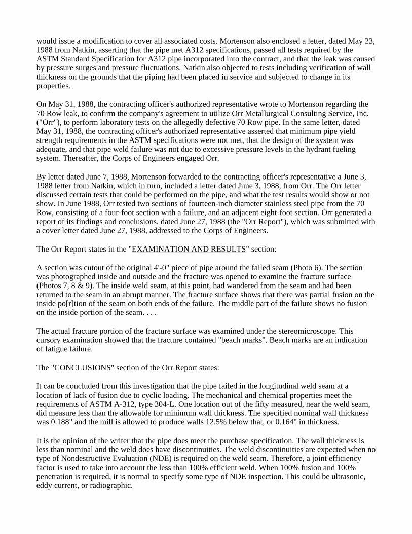
The Orr Report states in the "EXAMINATION AND RESULTS" section:
A section was cutout of the original 4'-0" piece of pipe around the failed seam (Photo 6). The section was photographed inside and outside and the fracture was opened to examine the fracture surface (Photos 7, 8 & 9). The inside weld seam, at this point, had wandered from the seam and had been returned to the seam in an abrupt manner. The fracture surface shows that there was partial fusion on the inside po[r]tion of the seam on both ends of the failure. The middle part of the failure shows no fusion on the inside portion of the seam. . . .
The actual fracture portion of the fracture surface was examined under the stereomicroscope. This cursory examination showed that the fracture contained "beach marks". Beach marks are an indication of fatigue failure.
The "CONCLUSIONS" section of the Orr Report states:
It can be concluded from this investigation that the pipe failed in the longitudinal weld seam at a location of lack of fusion due to cyclic loading. The mechanical and chemical properties meet the requirements of ASTM A-312, type 304-L. One location out of the fifty measured, near the weld seam, did measure less than the allowable for minimum wall thickness. The specified nominal wall thickness was 0.188" and the mill is allowed to produce walls 12.5% below that, or 0.164" in thickness.
It is the opinion of the writer that the pipe does meet the purchase specification. The wall thickness is less than nominal and the weld does have discontinuities. The weld discontinuities are expected when no type of Nondestructive Evaluation (NDE) is required on the weld seam. Therefore, a joint efficiency factor is used to take into account the less than 100% efficient weld. When 100% fusion and 100% penetration is required, it is normal to specify some type of NDE inspection. This could be ultrasonic, eddy current, or radiographic.
The eight-foot section from the 70 Row, which exhibited an apparent crack on the inside seam, met the requirements of the tests designed to qualify the material to meet the A312 specifications: a chemical analysis, a transverse tensile test, and a flattening test. The Orr Report concluded that "the pipe does meet the purchase specifications" of ASTM A312 piping despite the fact that one point of pipe wall measured "less than the allowable for minimum wall thickness" required by the ASTM standard specifications. Dr. Allen Selz, plaintiff's expert in design, failure analysis and fatigue, and a member of the ASME's Subcommittee on Inspection Methods, testified about this apparent inconsistency that the pipe met the ASTM requirements but had a point of wall thickness below the standard deviation:
Q Do you recall that Dean Orr found that the pipe he tested and analyzed still met the ASTM A312 specifications, notwithstanding that measurement?
A He stated so. That's correct.
Q Could you tell us, sir, what is your view as to whether that measurement that Dean Orr made at 161 thousandths did render that pipe not in compliance with ASTM A312?
A Recognize that the measurements were taken on the failed piece of pipe right near the weld; not at the weld, but a little bit back from the weld where the pipe failed.
The pipe, as one could see from the photographs before it was cut up, was distorted due to the bursting. The opening had fish mouthed. There was distortion of the material. It is difficult to take measurements on a distorted piece of material.
The very nature of the bursting is that the piping is overloaded. If that base material a little bit away from the weld was subjected to any stress beyond the yield strength, it would have stretched. If it stretches, it necks down. It reduces in thickness. Metal has a constant volume. If you make it longer, it is going to get thinner.
Those things I think could explain the difference between that post failure measurement and any measurement that was made on the new material.
Now, the other thing you have to recognize is that the .164 requirement is three-thousandths of an inch larger than the .161 requirement. Your Honor, this is a graphic explanation. Three-thousandths is the thickness of a piece of cigarette paper. It is just not very thick. There is not much difference in that measurement.
I believe that there is no way that I could say that that pipe was out of specification when it was new.
At trial, Mr. Dean Orr, who authored the Orr Report, elaborated on his statement in the report that "weld discontinuities are expected" and it is "normal" to specify an NDE inspection:
Q Now, continuing on, right where we were in the last paragraph of your report says, "Weld discontinuities are expected when no type of non-destructive evaluation is required on the weld seam." What is the basis for that statement that you have made there?
A That's my own expectation. That's my own opinion that over the years in inspecting welding and specifying welding, if you do not specify any non-destructive evaluation, you are expecting some discontinuities in the weld.
Most codes take that into account by using an efficiency factor of some type.
Mr. Orr also articulated in greater depth his determination that the rupture in the pipe was a result of cyclic loading that caused metal fatigue:
Q Did your review and evaluation of these samples of Ellsworth 14 inch pipe involve a fatigue analysis?
A Yes, when I studied the fracture surface, that was, in fact, a fatigue failure.
Q Tell us what it means to conduct a fatigue analysis? What did you do in the evaluation?
A Well, it's not really, not as much a fatigue analysis as it is an analysis of the fracture surface, and determine why the fracture, what caused the fracture to, the part to fail.
On the fracture surface, there were what are called beach marks, and beach marks get their name from a beach, a sand beach, where the water washes up on the beach and it leaves these parallel lines where the water washes up and comes back and it leaves parallel lines on the beach.
On the fracture surface, we had this type of marking and that is a -- the only way you get beach marks is from fatigue.
* * *
Q Now, you pointed out that beach marks are an indication of fatigue failure. Why is that? Tell me what that means?
A The beach mark is -- a fatigue failure is a progressive failure. It's a failure that moves very slowly through the metal and when the crack is being flexed or opened from time to time, it may leave a striation. Then, when the crack comes to rest for a period of time, then many times, not always but many times, a beach mark will be left.
In other words, if the crack is being opened and closed for a period of five minutes and then it comes to rest, there's no more fluctuation in the stress, then you would likely get a beach mark. Then, the next time it starts, the crack is opened and it progresses on until another rest period. And, then, it will cause another beach mark.
Q What is the mode of failure known as fatigue? What does that mean?
A The mode of failure known as fatigue is a mode of failure that is, in particular, caused by fluctuating or cyclic stress. It's a progressive failure, the progressive failure that I was describing earlier. It progresses through the material, a small step at a time.
Q Was the basis of the failure here fatigue?
A Yes, fatigue as opposed to over stress. If it's an over stress failure, this is normally a single cycle failure, where the, it's a single event failure. One pressure and the pipe or the fracture occurs.
Mr. Orr likewise explained at trial his final conclusion that the failure of the ASTM A-312 pipe stemmed from cyclic loading:
Q You conclude, the opening sentence under the word conclusion in your report says that, "It can be
concluded from this investigation . . ." and I take it that's your investigation, right?
A Yes.
Q ". . . that the pipe failed in the longitudinal weld seam at a location of lack of fusion due to cyclic loading." Now, how did you determine that it was due to cyclic loading?
A That's the only way you can get fatigue. You can't get fatigue from a static loading situation. It has to be a cyclic load to cause fatigue.
Similarly, plaintiff's expert concluded that "the failure was caused by the cyclic loading. The LOFs were clearly there, and that's where the failure occurred, but the cause was loading that was not accounted for in the design." And, according to Dr. Selz, the Ellsworth fuel system did not contemplate cyclic loading.
On December 22, 1988, the contracting officer's authorized representative notified Mortenson that a second break was suspected, in the 90 Row fuel line. By letter dated March 6, 1989, the contracting officer's authorized representative informed Mortenson that government personnel had exposed a portion of the 90 Row fuel line and that the government considered the failure to be a latent defect of the factory applied longitudinal weld in the 16-inch stainless steel pipe. Mortenson responded to the contracting officer by letter dated March 24, 1989. In response, Mortenson notified the contracting officer that it disagreed and that plaintiff would make no further repairs of the 90 Row pipe. Furthermore, plaintiff indicated that it planned to submit a claim for the repair and investigation work under the disputes clause to the contract.
Thereafter, government personnel exposed the line, removed a section of the pipe from 90 Row, and shipped it to the Corps of Engineers Construction and Engineering Research Laboratory ("CERL") in Champaign-Urbana, Illinois. The pipe was analyzed and a report issued, signed by Dr. Ellen G. Segan of CERL, a version of which was distributed under cover of memorandum, dated September 15, 1989 (the "CERL Report").(15) The CERL Report was prepared and written to plan for new hydrant fueling system design and not to understand liability of the failure or in anticipation of litigation. The CERL Report had a number of appendices, including a summary of the work of Cipolla, Grover, Beaupre & McHaughton, published in May 1980, titled: "Lack-of-Penetration Defects in Double-Seam-Welded SA-312 Stainless Steel Pipe."
The CERL Report analyzed the design of the hydrant fueling system. The CERL Report, section 4, entitled "DESIGN ANALYSIS," states in part:
4.1. Background
The piping system was designed with the ASME/ANSI B31.3 piping code for Chemical plant and petroleum refinery piping. There is no specific design code for underground fueling systems. As a result, the designer must use some judgement in selecting the appropriate sections of the Code. The code is used to determine the size and wall thickness (schedule) of the pipe required for a given pressure and number of operating cycles. ASTM A312 pipe was specified for this application. The general specifications of this pipe are reviewed first.
4.2. ASTM A312 Pipe Specification
The pipe was purchased to ASTM A312, Standard Specification for Seamless and Welded Austenitic Stainless Steel Pipes.
* * *
There is no specific requirement for weld quality. All of the specifications relate to performance under static loading. These tests will not determine performance under cyclic loading. Weld lack of fusion defects have clearly been demonstrated. The question becomes does a LOF defect constitute a lack of wall thickness? Common sense would dictate that the weld is part of the pipe wall and should be subjected to the wall thickness requirement. The question of whether the four failed pipes meet specifications will have to be addressed by the appropriate ASTM Committee. Clearly, the observed failures at the short service lives were associated with the deep LOF defects. The delivered products were generally able to meet the acceptance tests but there is question as to whether the pipe meets the minimum wall requirements in regions where there is lack of fusion. Some aspects of the acceptance tests are discussed below.
* * *
It is common practice in the pressure vessel industry to have specific requirements for weld quality and to make the weld inspection requirements part of the purchase specification. No weld inspection requirements were specified when purchasing this pipe therefore it could incorrectly be assumed by the supplier that weld quality was not critical.
(Footnote omitted).
The CERL Report, in its examination of the 90 Row pipe, discussed instances where there were exterior welds but the interior weld had wandered, at some locations to the point that no fusion occurred at the pipe wall abutting edges on the interior surface, and instances where a second weld pass was evident on the exterior of the pipe. Subsection 3.2 of the CERL Report, Metallurgical Examination, states:
Figure 14 shows a section of weld seam from the inside of the pipe from section 6 to section 8. Section 8, (Figure 5) shows that the weld was off center to the point that no fusion occurred on the surface. This LOF defect extended half way through the pipe thickness. A buried LOF defect is indicated on the other end shown in section 6 (Figure 4). All of the transverse sections near the failure crack show LOF defects that extend approximately half to two thirds of the wall thickness. Evidence of a second welding pass on the outside of the pipe is shown in figure 10.
The parties stipulated that where the void is located between areas of fusion on the inner and outer weld, the lack of fusion can be difficult to locate or detect.
The CERL Report concluded that the pipe in the 90 Row fuel line failed due to fatigue, as cracks, initiated at LOF locations, grew under cyclic loading. Additionally, the report found that the pipe manufacturer, Bristol, had delivered products which met acceptance tests even though the pipe contained LOF locations. Finally, the report advised that A312 pipe was not appropriate for the cyclic loading duty of hydrant fueling systems. The CERL Report concluded that the 90 Row fuel line failed at an LOF location from fatigue caused by cyclic loading.
Specifically, the section the CERL Report entitled "CONCLUSIONS AND RECOMMENDATIONS," states:
The conclusions and recommendations of this analysis are given below:
1. Failures of the fuel lines were the result of fatigue. Cracks initiated at LOF defects in the longitudinal welds and grew under the applied cyclic hoop stress until the remaining cross-section of the pipe was

unable to carry the pressure loading. . . .
2. The number of failures and the discovery of a large fatigue crack in an unfailed section of the pipe suggested additional failures are highly likely and these may occur soon (i.e. days or months) in operating systems. This conclusion is further supported by the work of Cipolla and Grover and the AS[ME]/ANSI B31.3 piping code which excludes A312 welded pipe for cyclic service conditions.
3. Bristol [Metals], Inc. delivered products were generally able to meet the acceptance tests while containing large LOF defects. Whether the presence of the LOF defects result in failure to meet the specification according to workmanship and minimum wall thickness criteria will have to [be] taken up with the appropriate ASTM Committee.
4. The design of the hydrant fuel systems using Schedule 10 welded pipe is not adequate for cyclic loading duty of the system. The piping code does not specifically address fatigue in design. Evidence from Cipolla and Grover suggest that potentially fatal flaws in A312 pipe cannot be found even with 100% radiography. The piping code specifically excludes welded A312 pipe for cyclic service and it is recommended that it be excluded from hydrant fuel system design.
5. * * *
DESIGN OF NEW SYSTEMS:
Welded ASTM A312 pipe is not appropriate for the cyclic loading duty of the hydrant fueling systems. Fatigue due to cyclic pressure was not specifically addressed in the ANSI/ASME B31.3 piping code under which these systems were designed, but given the observed failures, fatigue must now be considered. Modified design considerations for the piping system are summarized in Appendix B. It should be noted that similar design for remaining system components (e.g. valves, fittings[,] flanges, etc.) will need to be developed using similar criteria.
At trial, Dr. Ellen Segan, one of the authors of the CERL Report, upon questioning by plaintiff's counsel testified about the relationship between fatigue failure and cyclic loading:
Q And isn't it true that the mode of failure was found to be fatigue?
A Correct.
Q And did you not conclude that the modes of measure reflected that the fatigue failure was associated with cyclic loading of the system?
A Fatigue failures are associated with cyclic loading.
Q And, in fact, they are not at all associated with static loading, are they?
A Static? No. Fatigue failures are not associated with static loading.
Q Would you describe fatigue failures, please? How does that occur? How did it occur in this pipe from Ellsworth?
A In this particular case, an existing lack of fusion defect, as we describe it in this report, was a crack initiated under the cyclic loads of the system and that crack grew under the operating stresses, the
normal operation of the system, until the crack got to the size where the remaining wall thickness was not able to take the load any more and failed.
* * *
Q At Ellsworth, you called the loading to which the pipe was subjected severe because it was sufficient to cause severe fatigue cracks to the point of failure; isn't that true?
A Yes. . . .
Dr. Segan also reiterated that the hydrostatic pressure test required in the contract specifications was for all intents and purposes worthless in the face of cyclic loading:
Q Would you agree, Dr. Segan, that, in general, a hydrostatic test that does not burst the pipe is useless for any structure or component that is subjected to cyclic loading?
A In general, hydrostatic testing is not appropriate to determine the quality of the pipe unless you are willing to take the hydrostatic test to a very high pressure, which may yield for fail components in the system.
Q That is for a cyclically loaded use, right?
A Yes.
Q Hydrostatic pressures typically are associated with static use of pipe, aren't they?
A Hydrostatic testing is used in many different ways to accept systems.
Q And is one of the uses for systems that will be used under static loading?
A Yes.
Q So, in that instance, hydrostatic pressure tests are useful, are they not?
A They're marginally useful and they're called upon by the specifications.
Q Typically, right?
A Yes.
As a result of problems with longitudinal factory welds in piping and because of cyclic loading experienced in fuel systems, the standard criteria for hydrant fueling systems was changed by the government from A312 welded to ASTM A358 welded or ASTM A312 seamless piping.(16) A312 welded pipe is no longer to be used.
The CERL Report noted that the presence of LOFs in A312 welded pipe was made known to the industry by a study published in 1980, and that LOF voids between fusion on the inner and that outer pipe surfaces may be difficult to detect by radiography. (JtStip23) Subsection 4.4, titled "Summary," of the design analysis of the CERL Report states in part:
Paragraph 301.1 requires that fatigue due to pressure cycling must be considered in the design. The Code does not describe how fatigue should be considered. The designer must select the appropriate fatigue analysis from a source other than this section of the Code. . . .
ASTM A312 pipe has been extensively investigated for applications in the nuclear industry. A summary of the work from Cipolla, R.C., Grover, J.L., Beaupre, G.S., and McHaughton, W.P., "Lack-of-Penetration Defects in Double-Seam-Welded SA-312 Stainless Steel Pipe," prepared for EPRI by Aptech Engineering Services, May 1980 is given in Appendix A by reproducing appropriate text.
Results of these studies and experience with hydrant fueling systems demonstrates that ASTM A-312 pipe contains LOF defects, many of which cannot be identified with conventional post-weld inspection techniques. The piping code recognizes this and does not permit ASTM A312 welded pipe to be used under severe cyclic loading. This pipe should not be used in cyclic applications unless the influence of LOF defects is specifically taken into consideration in the design. Unfortunately this was not done in the case of the hydrant fueling systems.
(Footnote omitted).
At trial Dr.Segan testified that the Cipolla, et al., article presented a valid conclusion and concurred that ASTM Standard Specification A312 pipe satisfied the standard specifications even with numerous LOFs, which were to be expected in A312 pipe. In addition, Dr. Segan acknowledged that the pipe as delivered passed the requirements of ASTM Standard Specification A312, despite the LOF problems identified with the pipe. Moreover, Dr. Segan testified that ASTM Standard Specification A312 piping was not reliable for the use required at Ellsworth as the pipe lacks adequate safety margins in the ASTM specifications for use under cyclic loading conditions:
Q You made a recommendation in your report that for systems such as the Ellsworth hydrant fuel system, a pipe such as A-358, Schedule 20 pipe, or as you said the A-312 seamless pipe, would also be appropriate, I believe; isn't that right?
A That's correct.
Q Why is it that you made the recommendations of those pipes?
A Because you can do a fatigue designed system in A-358 or the A-312 seamless pipe to put into service and have adequate margin of safety.
Q Did you feel you would not have an adequate margin of safety with the Schedule 10 A-312 welded stainless steel pipe?
A The question is one of reliably locating all the flaws which might be present in the system in A-312 pipe.
Dr. Segan also testified that ASTM Standard Specification A312 piping was not appropriate for cyclic loading use even with additional NDE because these tests cannot adequately detect LOFs:
Q Can you find defects that go to 50/1000 reliably with NDE on Schedule 10 A-312 pipe?
A We, again, don't feel that it -- there is no indication of what size defect can be found with radiography of A-312. We don't know what that number is.
Q No data tells you what that number is.
A There are some data that indicate a distribution of those numbers, but there is no number that we know for sure would -- what is findable.
Q Is that one of the reasons why you thought the Schedule 10 welded A-312 pipe was not appropriate for this site with loading at Ellsworth?
A Yes.
Dr. Allen Selz, an expert for the plaintiff, admitted at trial as an expert in design, failure analysis and fatigue, and a member of the ASME's Subcommittee on Inspection Methods, likewise testified about the problems of LOFs in ASTM A312 piping:
Q How does one determine, in a set of specification requirements, weld quality if there is nothing set forth in, say, A-312 itself as to the penetration of the weld, or specifically the weld quality?
A There is no measurement of weld quality except the indirect measurement that's brought about by the tension test, the flattening test, and the hydrostatic pressure test.
Q Well, then, how does an owner or a specifier, a designer, indeed, make some provision for weld quality or weld testing? How do they determine what --
A A couple of things. First of all, A-312 is relatively difficult to weld without lack of fusion, to be sure that you don't have lack of fusion. To use a word used by Dr. Segan, it's not a very reliable way of welding the pipe to make sure that you don't have lack of fusion.
The two perpendicular surfaces that are butted together, because of difference in metallurgy from one batch of stainless steel to the next and because there's no filler metal added, result in a somewhat imprecise weld so that the -- there's no built-in reliability to the welding process. You could require radiographic inspection, radiographic non-destructive examination, or you could require, for example, ultrasonic examination. But there's an old saying you can't inspect quality into a product and you're going to have less likelihood of having -- you've got more likelihood of having lack of fusion in a 312 material than in another -- than another source of material.
But, certainly, the owner could invoke a non-destructive examination requirement and get a much greater assurance that he would find and be able to reject or repair lack of fusion. He could -- he could invoke radiography, the probable method of choice, or ultrasonic examination.
Q I want to make sure I heard you right. Did you say it was more likely or less likely that there would be lack of fusion in an A-312 pipe than some other types of pipe?
A More likely. More likely.
After the leaks were discovered, it was determined that each length of pipe removed from both 70 Row and 90 Row on the Ellsworth Air Force Base project was welded on the exterior surface. At some locations, the interior weld had wandered away from the abutting surfaces and at some of those locations it had wandered to the point that there was no fusion of the interior abutting surfaces, even though there was fusion on the exterior. If there is no lack of fusion of the weld, or if the lack of fusion of the weld is from one side, the depth may be measured. The presence of a lack of fusion between the interior and

exterior weld may in some instances be detected by certain NDE techniques such as radiographic or ultrasound.
In the instant case, the defendant does not dispute that cyclic loading conditions existed and that the ANSI piping design standards do not recommend A312 welded pipe for use where such conditions exist. In fact, the parties are in agreement that the hydrant fueling system at Ellsworth Air Force Base evidences cyclic loading conditions, and cyclic loading in the system is normal to its everyday operation. Moreover, the parties have stipulated that the defendant possesses no evidence that the pipe installed by plaintiff as part of the hydrant fueling system for the 70 Row and 90 Row fuel lines failed solely because of defects existing in the longitudinal seam welds.
Defendant did not monitor cyclic loading of the hydrant fueling system at Ellsworth Air Force Base from the time of the installation and initial operation of monitoring devices and during the twelve months thereafter. Natkin repeatedly informed both Mortenson and the government, as is evident, for example, in the letter of March 4, 1988 copied to both parties, that the monitoring devices needed to be regularly maintained, as they were critical to assessing and addressing problems with the hydrant fueling system:
[Natkin personnel] then asked to see the current strip chart from the flow and pressure recorder to interpret recent events and determine if pressure spike had occurred during the defueling operations. We were informed that no strip was available as the recording pens had run dry and had not been replaced. The flow (blue) recording pen has not be[en] repaired as of this date, as conveyed in our previous letter.
The strip charts generated by the recorder are an essential tool in diagnosing system operation problems as the date can be recorded on the charts and time notations may also be entered. The chart rolls are printed with a scale corresponding to travel time which makes it very easy to correlate events to specific time frame when properly monitored and marked.
We suspect that pressure spikes during defueling are causing relief valve(s) to discharge and fill the Waste Tank. . . . Lacking the strip charts for interpretation further compounds an intelligent study of the problem.
The hydrant fueling system was equipped with gauges and a recording system to monitor pressure and flow. Natkin trained United States Air Force personnel how to operate and maintain the chart recorder and turned the equipment over fully calibrated and in operational condition. The liquid fuel command at Ellsworth was responsible for servicing the recording equipment and collecting the strip charts. Although the recording system was not always in operation, the gauge permitted defendant's personnel to observe pressure and flow in the fueling system, and defendant contends that this was done periodically from the time of the fueling system's installation and initial operation and during the twelve months thereafter. The hydrant fueling system was not being monitored for cyclic loading at the times of the initial pipe ruptures of the 70 Row and 90 Row fuel lines. Defendant possesses no documentation of pressure/gauge readings or recordings of the hydrant fueling system from the time of its installation and initial operation and during the twelve months thereafter, except for strip charts for the period from February 14, 1988, through February 26, 1988. Thereafter, Drs. Segan and Socie as part of their investigation of the hydrant fuel system design, placed sensors at the locations of the pipe ruptures in order to measure pressure flow.(17)
With respect to Mortenson's and Natkins's investigation and repairs once the 70 Row and 90 Row leaks were identified, the following facts emerge from the record. On May 23, 1988, Natkin informed Mortenson of the steps it proposed to take to replace the failed pipe in the 70 Row. This letter discusses
the logistics involved in locating and procuring the material necessary to repair the section of failed pipe. Mortenson and Natkin advised the defendant, in a letter dated May 24, 1988, that the repairs requested would be undertaken with the understanding that if the testing did not confirm a latent defect the government would issue a contract modification to cover all costs. The government's response of May 31, 1989, concurred in Natkin's proposed testing and repair procedures so long as it could be established after examination that the remaining portions of the 40-foot length of pipe were found to be acceptable. A June 7, 1988 letter from Mortenson to the government states that "the damaged section of [70 Row] pipe has been removed for your review and a borescope inspection has been conducted on the remaining run of pipe. We are ready to continue with pipe line repairs."
After completion of the repairs on the 70 Row pipe and calculating of the costs involved, Natkin prepared an assessment of their efforts and forwarded them to Mortenson, which in turn became the basis of plaintiff's claim. Mortenson submitted its claim in the amount of $325,114.00 to the defendant for investigation and repair costs of the 70 Row leak. A letter, dated January 31, 1990, by Colonel Donald E. Hazen, the contracting officer at the Corps of Engineers, indicates the government's intent to deny Mortenson's claim for the 70 Row and outlines the investigation and repair efforts by Mortenson and Natkin:
FINDINGS OF FACT * * *
3. The fuel line in question was installed and put to beneficial use by the United States Air Force in the spring of 1987. In early May 1988, the Air Force, upon experiencing a pressure loss in the 70 Row hydrant fuel system, excavated and discovered the presence of an eight inch long break located in a 40 foot length of 14 inch diameter pipe between fuel pits 707 and 708. The contractor was promptly notified of this discovery and visited the site of the excavated pipe length on 6 May and again on 10 May 1988.
4. On 19 May 1988, representatives of the Contractor, Natkin & Company, the Contractor's mechanical subcontractor and BrisMet (Bristol Metals, Inc.) the pipe manufacturer and the Corps of Engineers met to discuss possible causes of the break and possible tests necessary to definitize those causes.
5. By letter dated 19 May 1988, the Resident Contracting Officer formally notified the Contractor of the pipe failure and directed it to take immediate action to replace the 40 foot length of pipe in which the failure occurred or a shorter section if the Contractor could prove that the remaining portion of the 40 foot length met the contract requirements. The Contractor was further directed to provide to the Resident Contracting Officer its plan of action by 25 May 1988.
6. On 24 May 1988, the Contractor responded by enclosing Natkin's letter of 2 May. Both the Contractor and Natkin refused to accept responsibility for the break, asserting that the cause was overpressurization by the user. Natkin proposed additional testing to determine the cause of the break and suggested repair procedures.
7. In response, the Contracting Officer's Authorized Representative advised the Contractor by letter dated 31 May 1988, that he did not agree that overpressurization was the cause of the failure. He suggested additional test procedures to determine the cause and concurred in Natkin's proposed repair procedure so long as it could be established that the remaining portion of the 40 foot length of pipe met the contractl requirements.
* * *
9. During the weeks of June 13 and 20, 1988, work necessary to accomplish the pipe repair was
accomplished by Natkin personnel. Two sections of the pipe were removed, one containing the failed longitudinal weld and the other an eight foot section immediately adjacent to the failed section. . . .
* * *
11. Because of its concern that there were other areas of incomplete or nonexistent fusion, the Corps of Engineers on 28 November 1988 directed the Contractor to conduct a video inspection of all of the welded surfaces of the pipe installed pursuant to its contract.
12. On 22 December 1988 the Contracting Officer's Authorized Representative notified the Contractor of a second fuel line break on 90 Row and again directed it to conduct the video inspection by December 27.
13. The video inspection of 80 and 90 Row and approximately 500 feet of 70 Row was completed on January 31, 1989. . . .
As stated above, by letter dated December 22, 1988, the government notified the plaintiff of a suspected second fuel line break on the 90 Row. In a letter dated March 6, 1989, the defendant informed Mortenson that government personnel had exposed a section of the 90 Row fuel line 445 feet north of the isolation pit to 80 Row and that the government considered the failure to be a latent defect. In a letter dated March 24, 1989, Mortenson disclaimed responsibility for the 90 Row failure, and informed the government "that Mortenson shall not take any further action toward the repair of the 90 Row Pipe." On July 31, 1989, the contracting officer issued his final decision, which was attached as exhibit A to the complaint in Case No. 90-390C (the Count I and Count II complaint), finding Mortenson liable for the cost the government incurred in repairing the leak in the 90 Row, together with any consequential damages:
FINDINGS OF FACT * * *
4. Following my Authorized Representative's directives, the contractor videotaped the entire lengths of the 80 and 90 Row systems and about 500 feet of the 70 Row in late January, 1989. Review of the tape of the 90 Row piping revealed indications of pipe wall separations resulting in directions to the contractor on February 3, 1989 to submit a repair plan. On February 23, 1989, my Authorized Representative notified the contractor of the location of the 90 Row failure and again requested a repair schedule. By letter dated March 6, 1989, the contractor was informed that government personnel had exposed the fuel line and again directed the contractor to submit its course of action or schedule for repair.
5. In telephone conversations on March 8 and 9, 1989, the contractor informed my Authorized Representative of its refusal to effect the requested repair on the 90 Row line. This refusal was confirmed in writing by the contractor's Serial Letter No. I C-881 dated March 24, 1989.
* * * DETERMINATIONS & REASONS THEREFOR
8. Based upon the results obtained from the testing of the pipe removed on the 90 Row fuel line as well as that conducted earlier on the 70 Row line, I conclude that the cause of the leak in the 90 Row line is the failure of the wall thickness at the longitudinal welded seam to meet the requirements of the contract specifications. This failure results from a lack of fusion and is clearly a manufacturing defect. I further find that the defective weld and the consequent insufficiency in pipe wall thickness is a latent defect not discoverable during ordinary and reasonable government inspections. Based upon the foregoing and in accordance with General Clause 60, INSPECTION OF CONSTRUCTION, I find you financially

responsible for any and all fuel line repair costs on the 90 Row line and for reasonably foreseeable consequential damages resulting therefrom. At the present time these costs total $48,873.32. However, should additional expense be incurred by the government in the repair or replacement of the 90 Row fuel piping or should the government incur any other reasonably foreseeable consequential damages resulting from the aforementioned or future fuel line breaks on the 90 Row line caused by welding which fails to meet the contract requirements, I reserve the right to augment the amount of the government's claim.
Prior to the contracting officer's determination regarding the 90 Row, on June 26, 1989, Mortenson had submitted its claim for investigation and for the cost of repairs to the 70 Row leak in the amount of $325,114.00. At the time the claim was submitted, Mortenson had demobilized the project office, the project manager had returned to Mortenson's Denver, Colorado office, no Mortenson personnel were located on site at Ellsworth Air Force Base, and the project was being administered out of Mortenson's Denver, Colorado office. By letter dated April 9, 1990 and identified by the contracting officer as his final decision, the contracting officer denied Mortenson's June 26, 1989 claim for $325,114.00 related to repairs and investigation on the 70 Row. The claim for $325,114.00 is incorporated into Count II of the first complaint filed in this court. As noted above, on July 31, 1989, the contracting officer held that Mortenson was liable in the amount of $48,873.32 for costs incurred by the government on the 90 Row, and this dispute is incorporated into Count I of the first complaint filed in this court.
The Corps of Engineers contract for the replacement of the Ellsworth hydrant fuel system was awarded in 1991. The new replacement design for the hydrant fueling system requires as a standard criteria ASTM A358 or A358M, Grade 304L, class 1 or class 3, with supplementary requirements, or A312, type 304L seamless pipe. A312 welded pipe is no longer to be used. Tests required in the new contract specifications include a 100% visual inspection, a liquid dye penetrant inspection, a 100% radiographic inspection of the factory welds, plus the required ASTM tests. The contract specifications also calls for radiography of field butt joints. The parties have stipulated that the reasons for the changes are because of problems with longitudinal factory welds in piping and because of cyclic loading experienced in fueling systems.
By letter dated February 11, 1994, relying upon specification Section 15R and the "INSPECTION OF CONSTRUCTION" clause, the contracting officer issued a decision which found that Mortenson was liable to the defendant for costs incurred by the government in redesigning and replacing the hydrant fueling system in the amount of $7,125,332.00. Subsequently, the plaintiff filed its Denial of Reprocurement Liability Claims in a separate complaint, Case No. 94-321C in this court, challenging the government's decision of February 11, 1994. In turn, the government filed a counterclaim, for costs associated with the replacement of the hydrant fuel system in the amount of $6,136,574.00. On June 15, 1994, the two cases (Counts I & II, Case No. 90-390C, and Denial of Reprocurement Liability Claims, Case No. 94-321C), were consolidated pursuant to court order.
DISCUSSION
The court enjoys the benefit of a considerable record, created during the course of the trial on liability. Extensive exhibits and testimony adduced from witnesses representing Mortenson, Natkin, Bristol, the Corps of Engineers, and numerous expert witnesses, has allowed the court to address this fact-laden dispute and to make the factual and credibility determinations required to resolve the disputes before the court.
Mortenson's earliest claim (Count II) first arose in May 1988, more than three years after the government awarded the contract to Mortenson, and a little over a year after the Air Force began utilizing the hydrant fueling system Mortenson had constructed. At the government's direction, Mortenson made repairs to the hydrant fueling system after the government had already accepted the

system. By terms of the relevant contract, however, the government's rights after acceptance of the work were limited. FAR Clause 52.246-12, entitled "INSPECTION OF CONSTRUCTION," was incorporated into the contract as part of the "INDEX OF CONTRACT CLAUSES," at paragraph 60, and, in relevant part, states:
(i) Unless otherwise specified in the contract, the Government shall accept, as promptly as practicable after completion and inspection, all work required by the contract or that portion of the work the Contracting Officer determines can be accepted separately. Acceptance shall be final and conclusive except for latent defects, fraud, gross mistakes amounting to fraud, or the Government's rights under any warranty or guarantee.
48 C.F.R. § 52.246-12(i) (1984). The "INSPECTION OF CONSTRUCTION" clause defines "work" as including, but not limited to, "materials, workmanship, and manufacture and fabrication of components." 48 C.F.R. § 52.246-12(a). This clause also provides for replacement or correction, at the contractor's expense, of work found not to conform to the contract requirements. 48 C.F.R. § 52.246-12(f),(g).
FAR Clause 52.236-5, entitled "MATERIAL AND WORKMANSHIP," was incorporated into the solicitation and contract as part of the "INDEX OF CONTRACT CLAUSES," at paragraph 46, and, in relevant part, states:
(a) All equipment, material, and articles incorporated into the work covered by this contract shall be new and of the most suitable grade for the purpose intended, unless otherwise specifically provided in this contract. References in the specifications to equipment, material, articles, or patented processes by trade name, make, or catalog number, shall be regarded as establishing a standard of quality and shall not be construed as limiting competition. The Contractor may, at its option, use any equipment, material, article, or process that, in the judgment of the Contracting Officer, is equal to that named in the specifications, unless otherwise specifically provided in this contract.
* * *
(c) All work under this contract shall be performed in a skillful and workmanlike manner. The Contracting Officer may require, in writing, that the Contractor remove from the work any employee the Contracting Officer deems incompetent, careless, or otherwise objectionable.
48 C.F.R. § 52.236-5(a),(c) (1984). However, in accord with the fact that the contractor must ensure the work is skillful and workmanlike the contractor is responsible for inspections and quality control.
The contract specifications in Section 1A, titled "SPECIAL CLAUSES," articulate the scope of responsibility for quality control to be undertaken by the contractor:
13. CONTRACTOR QUALITY CONTROL (CQC). In conformance with the requirements of CONTRACT CLAUSES clause: "Inspection of Construction," the Contractor shall provide and maintain an effective Quality Control Program.
13.1 GENERAL. Except for isolated tests or other items of work specified to be performed by the Government, the quality of all work shall be the responsibility of the Contractor. Sufficient inspections and tests of all items of work, including that of subcontractors, to ensure conformance to applicable specifications and drawings with respect to the quality of materials, workmanship, construction, finish, functional performance, and identification shall be performed on a continuing basis. The Contractor shall furnish qualified personnel, appropriate facilities, instruments and testing devices necessary for the
performance of the quality control function. The controls shall be adequate to cover all construction operations, shall be keyed to the proposed construction sequence and shall be correlated by the Contractor's quality control personnel.
During contract performance, the record indicates that Mortenson appears to have undertaken proper and extensive quality control efforts during the construction of the hydrant fueling system. At the time of the Ellsworth hydrant fueling system failure, the contract work had been accepted and the government's warranty rights had expired. The government, however, attempts to negate the conclusive nature of acceptance by claiming the existence of a latent defect.(18) See Spandome Corp. v. United States, 32 Fed. Cl. 626, 630 (1995) (citing United Technologies Corp. v. United States, 27 Fed. Cl. 393, 398 (1992)). In order to revoke acceptance and present a counterclaim under the latent defect theory, the government "must shoulder the burden of 'establishing the fundamental facts of liability, causation, and resultant injury.'"(19) Roberts v. United States, 174 Ct. Cl. 940, 956, 357 F.2d 938, 948-49 (1966) (quoting Wunderlich Contracting Co. v. United States, 173 Ct. Cl. 180, 199, 351 F.2d 956, 968 (1965)). See also Pennsylvania Dep't of Transp. v. United States, 226 Ct. Cl. 444, 451, 643 F.2d 758, 762, cert. denied, 454 U.S. 826 (1981).
The plaintiff, however, has argued that the defendant's specifications were defective, for which the government must bear the risk. See Hercules Inc. v. United States, 24 F.3d 188, 197 (Fed. Cir. 1994), aff'd, 516 U.S. 417 (1996) (citing United States v. Spearin, 248 U.S. 132, 136-37 (1918)) (noting plaintiff's burden to prove government's breach of implied warranty of contract specifications). To this argument, defendant responds that because Mortenson did not comply with the government's specifications in the first place, a contractor, such as plaintiff, who has not fulfilled its obligations under the contract should not be allowed to claim protection under a defective specification theory, absent "manifest inequity" or "a deviation from the specifications shown to have been entirely irrelevant to the alleged defect." See Al Johnson Constr. Co. v. United States, 854 F.2d 467, 469-70 (Fed. Cir. 1988).
Interpretation of a government contract is a matter of law. Grumman Data Sys. Corp. v. Dalton, 88 F.3d 990, 997 (Fed. Cir. 1996) (citing Fortec Constructors v. United States, 760 F.2d 1288, 1291 (Fed Cir. 1985)); Hol-Gar Mfg. Corp. v. United States, 169 Ct. Cl. 384, 386, 351 F.2d 972, 974 (1965). The language of the contract must be given the meaning that would be derived from the contract by a "reasonably intelligent person acquainted with the contemporaneous circumstances." Hol-Gar Mfg. Corp. v. United States, 169 Ct. Cl. at 388, 351 F.2d at 975 (citations omitted); Lockheed Support Sys., Inc. v. United States, 36 Fed. Cl. 424, 428 (1996) (citing Hol-Gar Mfg. Corp. v. United States, 169 Ct. Cl. at 388, 351 F.2d at 975).
When interpreting the language of a contract, a court must give a reasonable meaning to all parts of the contract and not render portions of the contract meaningless. Fortec Constructors, 760 F.2d at 1292 (citing United States v. Johnson Controls, Inc. 713 F.2d 1541, 1555 (Fed. Cir. 1983)); see also McAbee Constr., Inc. v. United States, 97 F.3d 1431, 1434 (Fed. Cir. 1996). To ascertain the intentions of the parties, the contract should be construed in its entirety "so as to harmonize and give meaning to all its provisions." Thanet Corp. v. United States, 219 Ct. Cl. 75, 82, 591 F.2d 629, 633 (1979) (citing ITT Arctic Servs., Inc. v. United States, 207 Ct. Cl. 743, 751-52, 524 F.2d 680, 684 (1975); Northwest Marine Iron Works v. United States, 203 Ct. Cl. 629, 637, 493 F.2d 652, 657 (1974)).
Courts will not read ambiguity into a contract provision as long as the contract as a whole or the interpretation of the contract language provides an unambiguous meaning. See International Transducer Corp. v. United States, 30 Fed. Cl. 522, 530 (1994), aff'd, 48 F.3d 1235 (Fed. Cir. 1995)). Whenever possible, courts look to a "plain language" or "plain meaning" interpretation of contractual documents. Aleman Food Servs., Inc. v. United States, 994 F.2d 819, 822 (Fed. Cir. 1993); Gould, Inc. v. United
States, 935 F.2d 1271, 1274 (Fed. Cir. 1991). The ordinary meaning of the language in contractual documents governs, and not a party's subjective but unexpressed intent. International Transducer Corp. v. United States, 30 Fed. Cl. at 526 (citations omitted). "Reasonableness is the standard." Id. at 527.
When a disagreement regarding the meaning of the words in a contract is presented to the court, the interpretation is a two-step process. The court must determine first whether an ambiguity in the words or term exists. John C. Grimberg Co. v. United States, 7 Cl. Ct. 452, 456, aff'd without op., 785 F.2d 325 (Fed. Cir. 1985). If an ambiguity is immediately apparent, it is referred to as a patent ambiguity, and the plaintiff is under a duty to seek clarification before submitting a bid. Newsom v. United States, 230 Ct. Cl. 301, 303, 676 F.2d 647, 650 (1982); see Fort Vancouver Plywood Co. v. United States, 860 F.2d 409, 414 (Fed. Cir. 1988) (citing United States v. Turner Constr. Co., 819 F.2d 283, 286 (Fed. Cir. 1987)). Although a potential contractor has a responsibility to inquire about a significant patent discrepancy, omission or conflict in the provisions, the contractor is not normally required to seek clarification of "any and all ambiguities, doubts, or possible differences in interpretation." WPC Enters., Inc. v. United States, 163 Ct. Cl. 1, 6, 323 F.2d 874, 877 (1963). If the plaintiff does not inquire about a patent ambiguity, then the ambiguity will be construed against the plaintiff. Beacon Constr. Co. v. United States, 161 Ct. Cl. 1, 7, 314 F.2d 501, 504 (1963).
In the event the court determines that the ambiguity in the contract was not patent, then "the contract is construed against its drafter if the interpretation advanced by the nondrafter is reasonable." Fort Vancouver Plywood Co. v. United States, 860 F.2d at 414 (citing United States v. Turner Constr. Co., 819 F.2d at 286); see also Grumman Data Sys. Corp. v. Widnall, 15 F.3d 1044, 1047-48 n.4 (Fed. Cir. 1994); ThermoCor, Inc. v. United States, 35 Fed. Cl. 480, 486 (1996). The alternative interpretation, however, must be within the "zone of reasonableness." WPC Enters. Inc., 163 Ct. Cl. at 6, 323 F.2d at 877.
Courts allow evidence of trade meaning, usage and custom to explain or define contract language, although such evidence may not be used to vary or contradict contract language. W.G. Cornell Co. v. United States, 179 Ct. Cl. 651, 669-70, 376 F.2d 299, 311 (1967); see also Astro-Space Laboratories., Inc. v. United States, 200 Ct. Cl. 282, 294 n.6, 470 F.2d 1003, 1009 n.6 (1972) (allowing evidence of technical publications and their trade nomenclature to demonstrate technical terms and established industrial meaning). A basic tenet of modern contract law is that the introduction of evidence on trade meaning, usage and custom is "an acceptable aid in interpreting contract terms." Tibshraeny Bros. Constr. Inc. v. United States, 6 Cl. Ct. 463, 470 (1984) (citing Gholson, Byars & Holmes Constr. Co. v. United States, 173 Ct. Cl. 374, 395, 351 F.2d 987, 999 (1965)). "[T]rade usage or custom may show that language which appears on its face to be perfectly clear and unambiguous has, in fact, a meaning different from its ordinary meaning." Gholson, Byars & Holmes Constr. Co. v. United States, 173 Ct. Cl. at 395, 351 F.2d at 999 (citations omitted).
I. Were the Design Specifications for the Hydrant Fueling System Defective?
It is established in government contract law that the government warrants the performability of the design specifications it issues. Neal & Co., Inc. v. United States, 36 Fed. Cl. 600, 627 (1996), aff'd, 121 F.3d 683 (1997) (citing United States v. Spearin, 248 U.S. 132, 136-37 (1918); Blount Bros. Corp. v. United States, 872 F.2d 1003, 1007 (Fed. Cir. 1989); Hol-Gar Mfg. Corp. v. United States, 175 Ct. Cl. 518, 525, 360 F.2d 634, 638 (1966)). The United States Supreme Court fostered this basic precept by stating in Spearin that "if the contractor is bound to build according to plans and specifications prepared by the owner, the contractor will not be responsible for the consequences of defects in the plans and specifications." United States v. Spearin, 248 U.S. at 136-37 (citations omitted). "Generally, 'design specifications created by the government contain an implied warranty that if the contractor adheres to the specifications, the result will be acceptable to the government.'" Neal & Co., Inc. v. United States, 36 Fed. Cl. at 627 (citing Ehlers-Noll, GmbH v. United States, 34 Fed. Cl. 494, 499 (1995) (quoting T.L.
Roof & Assoc. Constr. Co. v. United States, 28 Fed. Cl. 572, 578 (1993))).
The doctrine of an implied warranty for government design specifications, that was promulgated in United States v. Spearin, has been further defined by the United States Court of Appeals for the Federal Circuit:
Spearin stands for the proposition that when the government includes detailed specifications in a contract, it impliedly warrants that (i) if the contractor follows those specifications, the resultant product will not be defective or unsafe, and (ii) if the resultant product proves defective or unsafe, the contractor will not be liable for the consequences. Spearin, 248 U.S. at 136-37, 39 S. Ct. at 61. As with any contract-based claim, however, to recover for breach of warranty, a plaintiff must allege and prove (1) that a valid warranty existed, (2) the warranty was breached, and (3) plaintiff's damages were caused by the breach. San Carlos Irrig. and Drainage Dist. v. United States, 877 F.2d 957, 959 (Fed. Cir. 1989); accord Wunderlich Contracting Co. v. United States, 351 F.2d 956, 968, 173 Ct. Cl. 180[, 199] (1965) (stating that a plaintiff asserting a claim for breach of an implied warranty of specifications has the "burden of establishing the fundamental facts of liability, causation, and resultant injury."). . . . [T]he implied warranty of specifications covers problems arising after performance of the underlying contract. See Poorvu v. United States, 420 F.2d 993, 190 Ct. Cl. 640 (1970).
Hercules Inc. v United States, 24 F.3d at 197. In addition, it is a basic tenet of this legal doctrine that:
The implied warranty is not overcome by the customary self-protective clauses the government inserts in its contracts . . . requiring the contractor to examine the site, to check the plans, and to assume responsibility for the work, including its safekeeping, until completion and acceptance.
Al Johnson Constr. Co. v. United States, 854 F.2d at 468; see also United States v. Spearin, 248 U.S. at 137 ("The duty to check plans did not impose the obligation to pass upon their adequacy to accomplish the purpose in view."). However, the Court of Appeals for the Federal Circuit commented on the competing interests often present in a defective specifications case:
We think the restriction of the implied warranty to those who have fulfilled the specifications, or tried and failed to do so because of the defects themselves, has strong policy behind it that would not be served by allowing the implied warranty to run to one who has not done what he contracted to do and fails to satisfactorily explain why not. Any other exception should therefore be restricted to instances . . . of manifest inequity, or to a deviation from the specifications shown to have been entirely irrelevant to the alleged defect.
Al Johnson Constr. Co. v. United States, 854 F.2d at 470. The defendant's obligation, in a dispute over a construction contract that contains both latent and patent defects along with "faulty" specifications, is to delineate damages resulting from the latent defects as distinguished from the costs incurred due to patent defects and defective specifications. Roberts v. United States, 174 Ct. Cl. at 957, 357 F.2d at 948-49. Failure to satisfy this burden renders the government without entitlement to recover on a latent defect counterclaim. Id.
The defendant argues that the Corps of Engineer's "decision not to use A312 welded pipe to replace the ruptured pipe" should not lead to the conclusion that the original specification was defective. The defendant cites Martin Lane Co. v. United States, 193 Ct. Cl. 203, 218, 432 F.2d 1013, 1021 (1970), in suggesting that the decision "to install a type of pipe less susceptible to undetectable lack of fusion" is not an admission of faulty design. (D'sPTBp37) However, in Martin Lane Co. v. United States the court was not addressing issues in a defective design case, but rather ambiguity and clarity in contract

language. Id. ("The clarification cannot serve to forgive an unreasonable interpretation of the earlier language, nor properly be regarded as an admission that it was in fact ambiguous. While defendant may have drafted a subsequent contract 'with greater clarity' than it did plaintiff's, it does not follow that plaintiff's was 'ambiguous so as to require that the scales to be weighted against the Government.'") (quoting N. Fiorito Co. v. United States, 189 Ct. Cl. 215, 222, 416 F.2d 1284, 1288 (1969)). The court is hard-pressed to extract from the current action that the change in pipe specification is simply the clarification of ambiguous language in the contract.
In making these arguments, defendant attempts to discount the selection of higher grade piping in subsequent procurements and change orders, along with the accompanying admissions by the Corps of Engineers that the hydrant fueling system design did not address cyclic loading and fatigue, and that "[t]he necessity for this modification is the result of a design deficiency. The existing contract requires the installation of ASTM A 312 Schedule 10 stainless steel pipe for the JP-4 Fuel System which has been determined to be unsatisfactory for the intended use by CERL and the Department of the Air Force." Changes in specifications during the course of performance can be indicative of defective specifications:
The fact that the [defendant] implemented an additional underground drainage system behind the northern row of houses is also evidence that the original design was inadequate. See Appeal of McNally Indus., Inc., ASBCA 43027, 93-3 BCA ¶ 26,130 (Government's issuance of changes to "correct design errors" was held to prove original specifications were defective). While the contractor has the burden of proving that the detailed requirements of the specifications are defective, "the actions of the Government during performance of the contract may demonstrate such defects." Cibinic & Nash, at 281. See Big Chief Drilling Co. v. United States, 26 Cl. Ct. 1276, 1295 (1992) (finding defective drilling specifications where the Government refused to permit relaxation of drilling requirements on first well, but granted a blanket deviation on subsequent wells); . . .
Neal & Co., Inc. v. United States, 36 Fed. Cl. at 628.
The plaintiff in the instant action, however, goes one step further and asks the court to consider admissions and changes to specifications, not during the course of performance but for subsequent procurements, as evidence of faulty design specifications. The concern of the court is whether this evidence is remedial in nature and thus should be excluded or not given weight under the Federal Rules of Evidence. See Fed. R. Evid. 407. The court in Neal & Co., Inc. v. United States addressed the application of Rule 407 in a similar context:
the primary purpose of the rule prohibiting evidence of remedial measures is twofold to prevent prejudice to the defendant where the jurors would equate subsequent design modifications to an admission of a defective design; and to further the social policy of encouraging manufacturers to create safer products. Raymond v. Raymond Corp., 938 F.2d 1518, 1522-23 (1st Cir. 1991). See Baumann v. Volkswagenwerk Aktiengesellschaft, 621 F.2d 230, 233 (6th Cir. 1980). The case at bar is not a negligence action involving a consumer product or service, nor is it before a jury. . . . [T]he purpose of Rule 407 would not be served by the exclusion of this evidence. See Appeal of McNally Indus., Inc., ASBCA 43027, 93-3 BCA ¶ 26,130, 1993 WL 190382 (May 20, 1993). In any event, evidence of remedial measures does not run afoul of Rule 407 when it is used to prove the feasibility of a particular measure. Southland Enters., Inc. v. United States, 24 Cl. Ct. 596, 603 (1991).
36 Fed. Cl. at 626 n.49; see also Southland Enters., Inc. v. United States, 24 Cl. Ct. at 603 (finding Rule 407 not applicable and thus allowing admission of evidence of subsequent government redesign). However, although the court will consider the evidence in the instant case, the court recognizes that evidence of measures taken after an event are of limited use and are insufficient to demonstrate proof of liability. See Fed. R. Evid. 407 advisory committee's notes ("the rule rejects the notion that 'because the
world gets wiser as it gets older, therefore it was foolish before.'" (quoting Hart v. Lancashire & Yorkshire Ry. Co., 21 L.T.R. N.S. 261, 263 (1869))).
Plaintiff argues that the specifications were defective because the hydrant fueling system at Ellsworth was designed without the recognition and consideration of cyclic loading conditions, or the resulting fatigue. In particular, the plaintiff points to the contract specifications, the ANSI Standard B31.3, and thetestimony of witnesses to demonstrate that the design was inadequate for the purpose intended. Defendant attempts to rebut by stating that the ANSI Standard B31.3 allows for cyclic loading that is less than severe, that the ANSI Standard B31.3 need not be followed (despite incorporation into the contract), and that the plaintiff provided latently defective pipe, thus, failing to meet the specification requirements.
The ANSI Standard B31.3, as incorporated into the contract, clearly requires the defendant to comply with the piping code when establishing "requirements for design, construction, examination, inspection, and testing" for a fluid handling system. The defendant, acting as the designer, is directed under this piping code, to ensure "that the engineering design of piping complies with the requirements of the Code." Notably, the code demands that the designer consider design pressures at the "most severe condition." (301.2) In addition, most severe conditions are presumed in the event that "[t]he number of cycles (or variations) . . . exceed 7,000 during the life of the piping system." The code also mandates that in designing the system in "no case shall the increased pressure exceed the test pressure used . . . for the piping system." An additional criteria is that "[t]he combined effects of the sustained and cyclic variations on the serviceability of all components in the system have been evaluated." (302.2.4) The code also demands in a separate section that "[f]atigue due to pressure cycling, thermal cycling, and other cyclic loading shall be considered in the design of piping." (301.10)
The defendant has essentially conceded that it failed to meet this ANSI standard and that, in fact, cyclic loading is normal to the everyday operation at Ellsworth. At the trial, during a colloquy with plaintiff's counsel, Dr. Segan, a design expert and an author of the CERL Report, acknowledged the severity of cyclic loading in the hydrant fueling system:
Q At Ellsworth, you called the loading to which the pipe was subjected severe because it was sufficient to cause severe fatigue cracks to the point of failure; isn't that true?
A Yes. . . .
Testimony from defendant's and plaintiff's witnesses indicates that the system is estimated to have 30,000 cycles a year, with hundreds of those cycles significantly above the maximum test pressure for the system. The CERL Report states that "[a]ll specifications relate to performance under static loading." This is indisputably a serious flaw in the design specifications.
The issue is then simplified to one of analyzing the appropriateness of the defendant's specification of ASTM Standard Specification A312 piping when designing the system. The CERL Report notes, after suggesting that ASTM A312, schedule 10, piping not be used in future hydrant fueling system designs, that "[t]he piping code specifically excludes welded A 312 pipe for cyclic service." (CERLp12) This report likewise notes that "ASTM A312 pipe ha[d] been extensively investigated" prior to the design of the Ellsworth system and reiterates that LOF issues associated with ASTM A312 pipe had been recognized previously:
Results of these studies and experience with hydrant fueling systems demonstrates that ASTM A-312 pipe contains LOF defects, many of which cannot be identified with conventional post-weld inspection

techniques. The piping code recognizes this and does not permit ASTM A312 welded pipe to be used under severe cyclic loading. This pipe should not be used in cyclic applications unless the influence of LOF defects is specifically taken into consideration in the design. Unfortunately this was not done in the case of the hydrant fueling systems.
(Footnote omitted).
Dr. Selz testified as to the use of ASTM A312 in the engineering and designing of the Ellsworth hydrant fueling system:
The A-312 has an undefined -- has the possibility of having an undefined lack of fusion. It is exposed to cyclic pressure loading. The cyclic application of pressure has been a cause of a lack of fusion -- cause a crack to emanate from the tip of that lack of fusion and gradually penetrate the wall so that at some indeterminate time, that pipe is -- is likely to fail. And so the designer -- how can a designer design a system and -- and not know what its lifetime is? He has to be able to determine what its lifetime is.
He doesn't -- if he just defines A-312 with no inspection and -- and indeterminate lack of fusion, he doesn't know enough to be able to determine the lifetime of the system. He can't design it.
Later in the trial Dr. Selz elaborated as follows:
The lack of fusion that is a great issue here happens in this piping. It is normal. It is expected. It is part of the process.
The designer then is faced with what does it do. He can either accept the fact that there is going to be lack of fusion and just have a hydrostatic pressure test performed and the other mechanical tests, which will weed out egregious like affusion, or if he has a service that requires something better than this he can require another examination.
He can specify radiography or eddy current testing or ultrasonic testing and repair the repairable imperfections, the imperfections that are of sufficient magnitude to require repair. This pipe is then hydrostatically tested and is passed on for use.
Significantly the CERL Report states that "[i]t is common practice in the pressure vessel industry to have specific requirements for weld quality and to make weld inspection requirements part of the purchase specification." NDE inspection of the weld seam could have been specified in the contract, or particular ASTM specifications could have been required for the piping. Dr. Selz testified:
Two problems exist with 312 pipe. First of all, the defects, the lacks of fusion, are sometimes hard to find because the butt ends of the pipe are squeezed together by weld shrinkage, but there could be a lack of fusion. They are just hard to pick up with radiography.
Number two, those lacks of fusion are not -- are more common than they would be in pipe such as A358. A358 has the two advantages of having less likely lacks of fusion or crack like indications and those imperfections being more readily discernable.
If one is really worried about imperfections and lack of fusion, one should really use a different specification.
The evidence demonstrates that the defendant did not consider pressure surging which resulted in severe

cyclic loading, nor did it consider fatigue criteria arising from cyclic loading in the design of the Ellsworth hydrant fueling system. The government also failed to select pipe that is appropriate for a severe cyclic loading environment such as at Ellsworth according to engineering studies available at the time of designing the system. Instead, the defendant selected ASTM Standard Specification A312 pipe that is specifically excluded in the pressure piping code, ANSI Standard B31.3, from the class of pipe appropriate for severe cyclic loading, and thus ASTM A312 is not sufficient for severe cyclic loading and the resulting fatigue. Plaintiff, therefore, has demonstrated that the government provided defective specifications.
II. Was the ASTM Standard Specification A312 Pipe a Latent Defect?
"[A] latent defect is one which cannot be discovered by observation or inspection made with ordinary care." Kaminer Constr. Corp. v. United States, 203 Ct. Cl. 182, 191, 488 F.2d 980, 984 (1973) (citing Black's Law Dictionary 1026 (4th ed. 1968)). The government has the burden of "prov[ing] by a preponderance of the evidence that a latent defect existed at the time of final acceptance which was hidden from knowledge as well as sight, and could not be discovered by the exercise of reasonable care." Spandome Corp. v. United States, 32 Fed. Cl. at 630 (citing United Technologies Corp. v. United States, 27 Fed. Cl. at 398); see Southwest Welding & Mfg. Co. v. United States, 188 Ct. Cl. 925, 940-41 n.7, 413 F.2d 1167, 1176 n.7 (1969) (noting the Board of Contract Appeals found that "the burden is upon the Government to demonstrate" non-compliance with contract specifications); Roberts v. United States, 174 Ct. Cl. at 956, 357 F.2d at 949 (stating government "must shoulder the burden" of proof to establish liability, causation, resultant injury in latent defect counterclaim). This court looks to the contract specifications as "the standard for determining defects." United Technologies Corp. v. United States, 27 Fed. Cl. at 397 (citing 48 C.F.R. § 10.001 (1992); W.C. Fore Trucking, Inc., ASBCA No. 32156, 89-2 BCA ¶ 21,869, 1989 WL 46971 (1989)).
In Southwest Welding & Mfg. Co. v. United States, a case factually relevant to the instant claim, our predecessor court examined contract specifications involving the lack of fusion in the welding of pipe:
These were typically design (and not performance) specifications. They specified, in detail, the type of steel to be employed, and this steel was inspected and approved in accordance with the specifications. Welding procedures, the method of obtaining approval thereof, and the qualifications of welders, were set forth in great detail. . . . The testing and inspection requirements for the welding were set forth in great detail and were unusually stringent. They established, in effect, the performance standard to which the contractor was obliged to adhere. The test specified to determine compliance with contract requirements, and the contract requirements, constitute an equation.
188 Ct. Cl. at 952, 413 F.2d at 1183 (footnotes omitted). At issue in Southwest Welding was whether the government imposed a "'more severe inspection procedure or a more severe standard for acceptable welding than was set forth in the original contract.'" 188 Ct. Cl. at 954, 413 F.2d at 1184 (quoting the Army Corps of Engineers Board of Contract Appeals). The court insisted that when the government examines if the "original specifications were sufficient to insure the integrity of the welding," 188 Ct. Cl. at 951, 413 F.2d at 1183, by undertaking a more stringent application and interpretation of contract specifications the conclusion would be "inescapable that the Government is questioning the sufficiency of its own specifications." 188 Ct. Cl. at 954-55, 413 F.2d at 1185. The court formulated a framework for examining latent defects in holding that, for three reasons, these welding fusion flaws:
were not latent defects because they were fully known, or readily discoverable by the reasonable means of inspection prescribed by the contract; or else they were not rejectable defects at all because not interdicted by the inspection and performance standards set forth in the contract.
188 Ct. Cl. at 957, 413 F.2d at 1186; see General Am. Transp. Corp. v. Sun Ins. Office, Ltd., 369 F.2d
906, 908 (6th Cir. 1966) (finding "defective welding" not a latent defect because "this defect could have been discovered with proper inspection, such as radiography."). Simply stated, defects are not grounds for rejection of performance under the contract after acceptance, if the defects are (i) known, or (ii) readily discoverable by a reasonable means of inspection identified within the contract, or (iii) not prohibited by the inspection and performance standards set forth in the contract. Id.
This reasoning was likewise applied four years later in a case concerning latent defects, Kaminer Constr. Corp. v. United States, in which the court found that a "deficiency regarding 16 bolts in the 11,967-bolt structure was hardly an obvious discrepancy." 203 Ct. Cl. at 195, 488 F.2d at 987. The court upheld a Corps of Engineers Board of Contract Appeals determination "that the existence of the undersized bolts constituted a latent defect which could not have been discovered by reasonable Government inspection." 203 Ct. Cl. at 191, 488 F.2d at 985.
The examination by the Kaminer court mirrored the framework outlined by the court in Southwest Welding. The Kaminer court held that regarding discovery of defects during government inspection of work and materials:
Plaintiff contends that the undersized bolts were not hidden from sight and could have been discovered by the Government through the exercise of reasonable care and customary inspection methods. The court cannot agree with this contention and the board did not. The record indicates that there were 11,967 bolts on the tower and derrick. The Government had only one inspector present while the plaintiff had a work crew of approximately 60 men. Reason dictates that it was simply impossible for the Government inspector to check every bolt or oversee the work of each of plaintiff's 60 employees.
203 Ct. Cl. at 192, 488 F.2d at 985 (footnote omitted).(20) The court also noted that the government does not have a duty to inspect "absent a definition of the extent of the Government's inspection duties" simply because it has the right to inspect. 203 Ct. Cl. at 195, 488 F.2d at 987. Therefore, the Kaminer court addressed the last part of the Southwest Welding latent defect analysis by examining the performance and inspection standards contractually imposed upon the parties:
Plaintiff had the primary duty to insure that the "work performed under the contract [conformed] to contract requirements." This duty emanated from language considerably more specific than that referencing the Government's right to inspect. Only the failure of the Government to discover an obvious error in construction would have relieved plaintiff of its responsibility to insure that the tower and derricks were properly constructed. As we have already noted, the deficiency regarding 16 bolts in the 11,967-bolt structure was hardly an obvious discrepancy.
In addition, AISC specification 5(a) required that
Each fastener shall be tightened to provide, when all fasteners in the joint are tight, at least the minimum bolt tension shown in Table 3 for the size and grade of fastener used. [Table omitted.]
Threaded bolts shall be tightened with properly calibrated wrenches or by the turn-of-nut method. . . .
Plaintiff had an obligation to conform with these specifications. Had it done so, the inference is clear from the record that the use of the undersized bolts would have been discovered. In arguing that the Government's failure to employ either the "torque" or the "turn-of-nut" method of inspection caused the bolting deficiency to go unnoticed, plaintiff in fact admits that if either method had been employed the deficiency would have been discovered.
203 Ct. Cl. at 195-96, 488 F.2d at 987 (alteration in original). In other words, the obligations of the contractor "to perform in accordance with the contract specifications" and to "provid[e] conforming materials under the contract" are not relieved by the right of the government to inspect work. Granite Constr. Co. v. United States, 962 F.2d 998, 1003 (Fed. Cir. 1992), cert. denied, 506 U.S. 1048 (1993) (citations omitted). The corollary to this concept is that "the government cannot impose a more stringent testing procedure or standard for demonstrating compliance than is set forth in the contract." United Technologies Corp. v. United States, 27 Fed. Cl. at 397-98 (citing Southwest Welding & Mfg. Co. v. United States, 188 Ct. Cl. at 951-53, 413 F.2d at 1183-84); see SMS Data Prods. Group, Inc. v. United States, 17 Cl. Ct. 1, 10 (1989) (holding that "imposing a changed acceptance test" upon plaintiff constituted contractual interference).
At trial the defendant called Earl R. Sullivan, Director of ASTM for 18 years, and staff manager to several ASTM committees, including the committee having responsibility for issuing standards relating to ASTM A312 pipe. During Mr. Sullivan's testimony the defendant entered into evidence two letters, dated October 11, 1988 and January 19, 1990 respectively, containing interpretations from the ASTM subcommittee responsible for issuing standards on stainless steel pipe such as ASTM A312. In Bethlehem Steel Corp. v. Occupational Safety & Health Review Comm'n, the Court of Appeals for the Third Circuit suggested that an ANSI interpretation was not binding "although the views of experts in the field who are members of the organization which prepared the standards are entitled to consideration." 573 F.2d 157, 159 (3d Cir. 1978).
The court had the benefit of live testimony from experts, who are members of this same professional organization, albeit different subcommittees, and who testified in greater depth as to the same issues addressed in the ASTM subcommittee letter interpretations. Moreover, it is somewhat ironic that counsel for both sides labored extensively to render interpretations of the ASTM subcommittee interpretations, even after Mr. Sullivan testified that "[w]hat we say in ASTM is the standard speaks for itself." Mr. Sullivan further undermined the probity and weight that the ASTM interpretations were to be given by the court upon admission into evidence during the course of his testimony:
Q Now, Mr. Sullivan, does this response signed by you to Mr. Kelley, does that represent the official response of ASTM?
A No.
Q Was it authorized by ASTM?
A When you say ASTM, authorized by whom do you mean?
Q I am asking you, sir.
A I don't know the degree of authorization that you are referring to.
Q Was this response endorsed by ASTM?
A ASTM, how can that be endorsed by 30,000 members?
Q Is the response sanctioned by ASTM, sir?
A Is the response sanctioned by ASTM? This is not an ASTM response. So therefore, I don't see any relevance in the question.

Q This is not an ASTM [response]?
A No, it's not an ASTM response. It clearly states that it is a task group. It's a group of experts within the committee who received this inquiry and had responded. If you see, I put exactly what they give me to send on behalf of the task group. I'm acting as a conduit, as their staff manager. It does not represent an ASTM response. It's not sanctioned by the Board of Directors. It is not sanctioned by 30,000 members. People who understand ASTM know that when standards are developed, they go through a very rigorous due process.
It is the opinion of the court, based upon the above, that the probity of these two letters regarding ASTM Standard Specification A312 is limited. The focus on the wall thickness of the ruptured pipe, and in particular whether the weld itself must satisfy the ASTM A312/A530 wall thickness requirements, is best assessed based upon the testimony of each party's experts.
Defendant's expert Dr. Socie, who assisted in the fatigue analysis presented in the CERL Report, repeatedly represented that the "common sense" approach to examining the longitudinal weld was to consider it as part of the wall and, thus, subject to the wall thickness requirements. Under this theory, which is not supported directly by any portion of the ASTM Standard Specifications A312, where the welds do not match an LOF occurs that is likely not to satisfy the wall thickness of .188 (with an acceptable deviation to .164). This argument is plausible, however, on cross-examination it was demonstrated that Dr. Socie prepared a report on a length of ruptured SWEPCO pipe in a report titled "Diego Garcia Hydrant Fueling System Failure Analysis," in which he elected to consider the welds by a different criteria and not under the wall thickness requirement:
Q Dr. Socie, you also measured the lack of fusion at the weld to be 141,000ths or 75 percent of the wall thickness of that pipe, did you not?
A Yes.
Q You did not include that lack of fusion as part of your wall thickness measurement for conclusion, did you?
A I didn't [i]nclude wall thickness. I merely measured the wall thickness of the pipe and recorded what I measured.
Q You did not include weld though in the wall thickness measurements, did you?
A When I reported the measurements of wall thickness here, I measured with the micrometer and reported the measurements that I got. I did not report the dissection.
* * *
Q In any event, in your report here, you measured separately the lack of fusion for weld depth and did not include that in your statement about the wall thickness measurements?
A I measured the depth of the lack of fusion and included that separately from the measurement about nominal wall thickness.
This evidence undermined the credibility of the witness' earlier testimony and assertions as to whether wall thickness criteria are uniformly applied to examining longitudinal welds and calls into question Dr. Socie's analysis and conclusion.

In contrast, plaintiff's expert, Dr. Selz, convincingly and carefully articulated an interpretation that was reasonable and consistent with the totality of criteria by which piping is evaluated and measured:
Q In your opinion, Dr. Selz, does the wall thickness requirement and the permissible variation set forth in Section XI of A-530 apply to the weld itself at the seam of the pipe?
A No, it does not.
Q Could you explain that, please, sir?
A Well, fundamentally, because the wall thickness refers to the thickness of the steel away from the weld. No -- no requirements are -- appear in 530 or 312 on the dimensions of the weld or on the -- or on the possibility of a lack of fusion, which is an issue here.
And as you've seen sketched in a number of places, one can measure the thickness of the pipe across -- over the weld. But there can be lack of fusion inside the weld which is totally invisible to anyone not using non-destructive methods and -- and would make the measurement invalid. So it's a measurement that is without meaning and it's not a requirement. There are not requirements placed upon the weld dimensions and so therefore the weld, which is a different entity than the wall, is not subject to the requirements of the wall -- of wall thickness.
You characterize a weld differently. You characterize a weld by the acceptable indications in it. You characterize it perhaps by the degree of lack of fusion that one permits. But you don't simply characterize it by a dimension.
Q How does one determine, in a set of specification requirements, weld quality if there is nothing set forth in, say, A-312 itself as to the penetration of the weld, or specifically the weld quality?
A There is no measurement of weld quality except the indirect measurement that's brought about by the tension test, the flattening test, and the hydrostatic pressure test.
Q Well, then, how does an owner or a specifier, a designer, indeed, make some provision for weld quality or weld testing? How do they determine what --
A A couple of things. First of all, A-312 is relatively difficult to weld without lack of fusion, to be sure that you don't have lack of fusion. To use a word used by Dr. Segan, it's not a very reliable way of welding the pipe to make sure that you don't have lack of fusion.
The two perpendicular surfaces that are butted together, because of difference in metallurgy from one batch of stainless steel to the next and because there's no filler metal added, result in a somewhat imprecise weld so that the -- there's no built-in reliability to the welding process. You could require radiographic inspection, radiographic non-destructive examination, or you could require, for example, ultrasonic examination. But there's an old saying you can't inspect quality into a product and you're going to have less likelihood of having -- you've got more likelihood of having lack of fusion in a 312 material than in another -- than another source of material.
But, certainly, the owner could invoke a non-destructive examination requirement and get a much greater assurance that he would find and be able to reject or repair lack of fusion. He could -- he could invoke radiography, the probable method of choice, or ultrasonic examination.
Q I want to make sure I heard you right. Did you say it was more likely or less likely that there would be lack of fusion in an A-312 pipe than some other types of pipe?
A More likely. More likely.
Subsequently, Dr. Selz also testified, as follows:
Q Can you summarize for us what your view is as to whether the wall thickness requirements apply at the point of weld in compliance with ASTM A312?
A First of all, ASTM gives one a definition of a specification. That definition basically says that a specification is something that sets out the requirements for the material of a process or whatever else is being specified and the provisions for its evaluation or inspection.
There are no requirements in A312 with regard to complete penetration or complete fusion. There are no methods set out for determination of that characteristic, so that is simply not a specified issue in A312. It cannot be evaluated by the same criteria as the wall is evaluated.
Now, that is not without precedent. There are lots of precedents in specifications and in codes. If one wants requirements on shell or plate material in a vessel or a pipe, one specifies those. You can ultrasonically exam for delamination of the base material. You can go on and on and do all kinds of examination. If one wants any of those things, they are specified, if appropriate.
Likewise, if a weld is to have complete fusion or is limited to a certain amount of reinforcement or crowning of the weld above the surface or a certain amount of undercutting below the surface of the plate, those things are defined in the specification. Therefore, there is a basis for acceptance and rejection.
No. To answer your question, you cannot judge the weld by the criteria for the wall.
In addition, the ASTM A312 pipe standard specifications have certain mechanical tests and chemical requirements. The mechanical tests and requirements are a transverse or longitudinal tension test, a flattening test, and a hydrostatic test. The parties have stipulated that the entirety of the A312 pipe utilized by Mortenson and Natkin, including the ruptured pipe in the 70 Row and the 90 Row, met the chemical properties and all tests specified in the ASTM Standard Specifications A312 and A530. In addition to the terms of the contract, Natkin required a certificate of compliance from the manufacturer, Bristol, that the delivered pipe met the ASTM A312 and A530 standard specifications. The ASTM A312 piping delivered for use at Ellsworth was required to satisfy pneumatic pressurized testing in order to be accepted according to the contract specification Section 15R, subparagraph 8.2, written by the government. The parties are in agreement that the pipe readily satisfied the contractual pneumatic test pressure specification. Dr. Socie, defendant's expert in metallurgy, failure analysis and durability analysis, however, testified that the hydrostatic pressure test was meaningless for a piping system subject to cyclic loading.
The testing and inspection requirements "established, in effect, the performance standard to which the contractor was obliged to adhere." Southwest Welding & Mfg. Co. v. United States, 188 Ct. Cl. at 952, 413 F.2d at 1183. The position adopted by the defendant regarding measurement of the weld by wall thickness criteria does not undermine the fact that the piping system as fabricated by Mortenson and Natkin satisfied every test and requirement in the contract specifications. In United Technologies Corp. v. United States, the Court of Federal Claims granted summary judgment for the plaintiff after finding
that the government had imposed a more stringent method of testing the materials than that required by the contract. 31 Fed. Cl. 698, 702 (1994). This determination stemmed from the fact that "[t]he alleged deficiency in the fatigue life methodology is solely the result of the government's failure to impose more stringent contract requirements." Id. The court concluded by stating "[t]he government is really asking the court to rewrite the contract in its favor. This the court cannot do." Id. at 703.
The court finds that the pipe was not latently defective, and in all likelihood was not defective at all. First, the pipe was not latently defective because the problem of LOFs in ASTM A312 pipe was known from, as stated in the CERL Report, the extensive investigations into ASTM A312 piping. Second, even if the government's engineers who designed the system in accord with ANSI B31.3 were to try to deny such knowledge, the defects alleged "were not latent defects because they were . . . not rejectable defects at all because not interdicted by the inspection and performance standards set forth in the contract." Southwest Welding & Mfg. Co. v. United States, 188 Ct. Cl. at 957, 413 F.2d at 1186. In other words, the piping utilized by Mortenson was not prohibited by the inspection and performance standards explicitly set forth in the contract specifications issued by the government.
Another factor that also demonstrates that the pipe was not latently defective is that the LOF were "readily discoverable upon any reasonable inspection prescribed by this contract or readily available." 188 Ct. Cl. at 956-57, 413 F.2d at 1186. Ironically the defendant demanded particularly detailed and stringent requirements for the welding of the girth field joints, to the extent of demanding 100 percent radiography. The contract specifications that demanded radiographic inspection, however, only call for radiography of field butt joints, and not the longitudinal weld seams, despite the availability of such testing and inspection methods. The fact that the specifications asked for 100 percent radiography, instead of the normal percentage of 5 to 10 percent raises questions. Moreover, Natkin's project manager, Mr. Soukup, testified that the requirement for heightened radiography testing is somewhat unusual. Therefore, had the government been concerned about examining the weld quality of the longitudinal welds, it could have specified more extensive testing for portions of the work beyond the field butt joints.
The government's right to inspect, notwithstanding that is has no duty to inspect, cannot relieve the defendant from what it today considers glaring inconsistencies and obvious LOFs. Dr. Segan and Mr. Cole, two of defendant's witnesses, testified that the interior welding of the pipe could have been visually inspected. No party at any time was required according to the contract specifications to examine the interior weld, nor did any party actually examine an interior weld during the entire performance of the contract. Thus, not only is it difficult to suggest that the interior weld was a critical weld, but equally difficult to suggest that inspection could not have occurred readily, if it was important. This fact scenario is not the same as the situation in Kaminer Constr. Corp. v. United States, in which a handful of bolts out of almost 12,000 bolts were defective and also subject to specific inspection requirements contractually imposed upon the plaintiff. 203 Ct. Cl. at 195, 488 F.2d at 987. Not only could radiography, which was specified for in other portions of the project in the instant contract, have discovered significant LOFs, but also a visual inspection of the interior longitudinal weld would have alerted the parties to potential problems.
The testimony of plaintiff's expert also casts into doubt the defendant's reliance on wandering welds as indicative of poor workmanship, since the piping could have satisfied certain chemical and mechanical requirements of ASTM Standard Specification A312 with a single exterior pass on the longitudinal weld, and the interior weld is undertaken to satisfy other mechanical specifications. Dr. Selz stated on direct examination:
Q Dr. Selz, I think we have learned this week, among other things, that the pipe made by Bristol had a weld from the interior and the exterior of the pipe, both sides of the seam as it were.

A Yes.
Q Would you comment on why that was an appropriate basis for weld?
A Right. It has been suggested that if that inside weld is so unimportant, why do it at all. Why not just weld from the outside?
Well, it turns out that the weld from the outside only on a piece of pipe of this relative thinness would probably have been fine to withstand the hydrostatic test. That is essentially what Mike Boling said just a few minutes ago, as a matter of fact. Welded from the outside only, it would have had enough strength probably to pass the hydrostatic pressure test. From that standpoint, that would not be an unacceptable thing to do.
There is nothing in the specification that says anything about having to weld from both sides. It just says you can't use filler metal. There is another requirement, though, and that is the tension test in which a tension specimen is taken through the weld. The entire specimen has to comply with the minimum ultimate tensile strength requirements of the base material. That means that the weld has to be as strong as the base material.
The way to get a reasonable assurance that that is going to occur is to have a weld with complete fusion. There is an obvious incentive for the manufacturer to try to get complete fusion. There are a few places, as we have talked about, where there is LOF, but certainly at the ends of the pipe where he is taking his tensile test specimen he is going to be able to see whether he has complete fusion. He is going to take his tensile specimen, and he is going to hopefully pass the requirements of ultimate tensile strength.
Now, if he welded from the outside only, it would be unlikely that he could do that. That's why. Basically I think that's the technical reason why they weld inside and outside.
Defendant produced Mr. Coryell who stated that he viewed wandering welds as an indication of substandard work, however, the pipe met all requirements delineated in ASTM Standard Specification A312. In sum, the defendant has failed to meet its burden of proving that the piping supplied by Mortenson was latently defective.
Moreover, it is apparent that the issue of wandering longitudinal welds and the resulting LOFs would not have been a problem if the hydrant fueling system was used in the manner it was designed for -- to carry static loads. Dr. Selz testified that under a pure static loading condition the piping would have lasted "forever." The court recognizes that pure static loading is not realistic, but that some variations are inevitable in any piping system. Dr. Selz testified regarding the longevity of the Mortenson produced piping system even under moderate cyclic loading conditions and the fact that the system was subjected to more severe variations in cyclic loading:
Q Apply that to the Ellsworth pipe so we can bring this closer to home.
A Okay. We have a piece of pipe that has been tested to 300 psi. It has a certain proven minimum wall thickness. If I now operate that at the designed pressure that I backed out a little while ago, 182 psi, with a variation of plus or minus 20 psi, for example, just selecting that very arbitrarily as a nominal kind of a fluctuation, that piping system would easily withstand the 600,000 cycles.
Back off on that for a minute. Dr. Socie, in his testing, determined that there were about 45,000 cycles applied to the piping in a year and a half of operation.

Q At Ellsworth?
A At Ellsworth. That is 30,000 a year. If you select a nominal 20 year life for the system, that is 600,000 cycles. Applying those 600,000 cycles of plus and minus 20 psi pressure variation, the piping will easily withstand that. In fact, the piping will ultimately have its wall thickness reduced by growth of the lack of fusion in about three times that long.
In other words, that piping would last 60 years before it would have the potential for leaking. I will venture that it would have failed for other reasons or would have been taken out of service for other reasons after 60 years.
Q Can you shorten that explanation a little bit now that you have gone through all the processes of your deliberations? Give us the punchline there again, if you would, Dr. Selz. You lost me.
A Okay. The punchline is that piping that passed the hydrostatic --
Q Stick with Ellsworth now.
A Ellsworth piping that passed the hydrostatic pressure test, which it had to pass, could have withstood a 182 psi static pressure with pressure oscillations of plus and minus 20 psi for a period of 60 years.
Q Do we know if the pipe at Ellsworth was subjected to pressures that were greater than 182 psi?
A Yes. Dr. Socie measured pressures that he said I believe were as high as 275 psi. The data that are shown in the Segan & Associate report go up to 250 psi.
Q You used a moment ago oscillations. Is that fluctuations?
A That is fluctuations.
It is apparent that the manner of operation which caused fluctuating pressures and severe cyclic loading conditions in the system at Ellsworth caused LOFs, normal to ASTM Standard Specification A312, to expand and eventually rupture.
Defendant also ignores the fact that the United States Air Force personnel "experimented" with and improperly operated the hydrant fueling system so severely as to damage gauges and components, and that the government failed to maintain the pressure recording gauges, which denied an opportunity to view precisely the type of loading that the Ellsworth fueling system was forced to withstand. The court should not ask the plaintiff to prove or disprove documentary evidence of the severity of the cyclic loading in a system that was in the dominion and control of the defendant,
who in turn elected not to maintain and operate the recording instruments. Therefore, not only can the defendant not prove a latent defect, but also the defendant cannot satisfy its burden of proof that such a latent defect caused the system to fail.
Defendant is required to delineate damages resulting from the latent defects as distinguished from the costs incurred due to patent defects and defective specifications. Roberts v. United States, 174 Ct. Cl. at 957, 357 F.2d at 948-49. If the government is unable to meet this duty, there can be no recovery on a latent defect counterclaim. Id. Based on the record before the court, especially defendant's expert witness Dr. Socie, the government is incapable of separating costs from latent defects as opposed to

defective specifications:
I concluded that the cause of failure of this pipe is there were large lack of fusion flaws, and these flaws after a small number of cycles, become a crack. This cracks grows through the structure. So this failure is a result of, first of all, the lack of fusion flaws. And the second part is the cyclic loads in the system were of sufficient magnitude to cause the cracks to grow.
(Emphasis added). This statement is buttressed by the fact that the parties have stipulated that the defendant possesses no evidence that the pipe installed by plaintiff as part of the hydrant fueling system for the 70 Row and 90 Row fuel lines failed solely because of defects existing in the longitudinal seam welds. Simply stated, the government is unable to precisely ascertain the damages from the alleged latent defects and any other defects or faulty specifications.
CONCLUSION
This court finds that the plaintiff has proven that the specifications provided by the defendant were defective. In addition, the government has not met its burden to establish that the pipe supplied by Mortenson evidenced latent defects as the pipe was most likely not defective, but if it is construed as defective that defect was in fact patent. Moreover, even if the pipe evidenced latent defects, the defendant has failed to demonstrate causation and cost damages stemming solely from defective piping as opposed to from faulty specifications. Plaintiff, therefore, is not liable for defendant's hydrant fueling system redesign and replacement costs.
In light of the determination that the government provided defective specifications and that the plaintiff used piping that satisfied the contract specifications, the plaintiff has demonstrated that the plaintiff is not liable for Count I regarding the costs incurred by the government for repairs to the 90 Row. The court also finds that the defendant is liable for the claims included in Count II regarding the expenses incurred by Mortenson and its subcontractors to repair and investigate the 70 Row fuel line.
IT IS SO ORDERED.
_______________________________________
MARIAN BLANK HORN
JUDGE
1. The complaint in Case No. 90-390C incorrectly alleges in paragraph 7 that the 70 Row leak was addressed by the contracting officer in the letter dated July 31, 1989. As exhibit A to the complaint demonstrates, the 90 Row, in fact, was addressed in the July 31, 1989 letter.
2. For the purpose of clarity, the claims pursued by the plaintiff in Case No. 90-390C are identified as Counts I and II, while the claims pursued by the plaintiff in Case No. 94-321C are identified, hereinafter, as the "Denial of Reprocurement Liability Claims."
3. American Society for Testing & Materials ("ASTM") is a private group which sets standards and specifications for, among other items, piping. ASTM issues an annual book of standards which establishes both definitions and specifications for materials and products.

4. A312 seamless pipe is more expensive than A312 welded pipe.
5. Another example referred to during trial is ASTM A813 piping, which requires full penetration of the weld as verified by an inspection standard that is agreed upon by the user and the manufacturer.
6. Defendant's welding expert, Kenneth Coryell, when asked whether the ASTM standards defines "automatic welding" responded: "I am unaware of any formal definition in the ASTM standard for that definition."
7. (8)
8. (9)
9. ' (10)
10. " " " " ' " " - -- "" ""
11. Michael Boling, vice-president of Bristol, testified that 100 percent radiography of the longitudinal weld increases the cost of piping by 40 to 50 percent, as the "x-ray and welding process" required to meet such specifications are expensive. Mr. Boling estimated that the price increase reflected in ASTM A358 pipe, which satisfies these additional radiography and weld specifications, is in the range of 100 to 130 percent more than ASTM A312 welded seam pipe.
12. Despite this testimony by government witnesses, defendant argues based on the testimony of their witness, Dr. Darrell Socie, that visual inspection of weld path missing the seam was "difficult if not impossible." However, the testimony of Dr. Socie was based on examination of a ruptured section of piping from Ellsworth after the pipe had been in use for over a year. Dr. Ellen Segan, Dr. Socie's colleague on the CERL Report produced by the laboratory of the Army Corps of Engineers, however, testified that when she inspected A312 pipe at another pipe manufacturer's plant she "took a flashlight . . . and went out to the stockpiled pipe and started looking for variations" in the interior weld of the pipe.
13. It is important to distinguish between (i) the welding of the circumferential field butt joints and (ii) the factory welding of the longitudinal seams of the pipe. The latter (factory welding of the longitudinal seams of pipe) is not covered by Section 15R, paragraph 5 of the contract specifications, while the former is specifically addressed in this section and paragraph of the contract. Contract specifications Section 15R, paragraph 5 at issue here called for radiography of field butt joints only.
14. Natkin correspondence at the time indicates that representatives of the Army Corps of Engineers were concerned about this increased pressure because the equipment "should not provide that high of pressure based on design criteria."
15. The CERL Report, other of defendant's documents, and defendant's representatives often use the word "defect" or phrase "LOF defect." "LOF" refers to partial lack of fusion in the factory-fabricated longitudinal weld of the pipe. Plaintiff contends that an LOF is not a defect because it does not violate any contract requirement, provision or specification. Defendant contends that the LOFs involved here do violate the contract requirements.
16. For example, hydrant fueling systems, other than at Ellsworth Air Force Base, such as at Diego Garcia Naval Base, which utilized ASTM A312 welded pipe, also experienced failures. In May 1991,
there was a fuel leak from a crack along the longitudinal seam of 18-inch ASTM A312 welded pipe on a hydrant fueling system at Diego Garcia Naval Base. The A312 pipe at Diego Garcia, however, was not manufactured by Bristol; it was supplied by another manufacturer, SWEPCO.
Similar LOF defects also were detected in welded pipe used in hydrant fuel systems at other air bases. Memorandum for Chief, Air Force Reserve Headquarters, United States Air Force Reserve, Washington, D.C., dated March 22, 1990, addresses failed hydrant fuel systems at Ellsworth, Kelly and McGuire Air Force Bases, at which Bristol supplied the pipe.
17. These measurements were, in part, the source of the estimated 30,000 cycles per year quoted by Drs. Socie and Segal. However, there was questioning at trial that indicated this number may not accurately reflect the total number of cycles or the extent of pressure surgings that the piping was exposed to because of the location of the monitoring devices and the fact that the system was improperly operated prior to the pipe ruptures and not necessarily thereafter.
18. As noted above, the contract's "Inspection of Construction" clause, incorporated from 48 C.F.R. § 52.246-12(i), states that "[a]cceptance shall be final and conclusive except for latent defects, fraud, gross mistakes amounting to fraud, or the Government's rights under any warranty or guarantee." See Decker & Co. v. West, 76 F.3d 1573, 1582 (Fed. Cir. 1996) ("Both as a matter of contract and as a principle of law, once the Government accepts the work required under the contract, that acceptance is binding on the parties.").
19. It is uncontested that the government suffered an injury in this case when the hydrant fueling system piping ruptured, which is the third element necessary to prove a latent defect under the test enunciated in Roberts v. United States, 174 Ct. Cl. at 956, 357 F.2d at 948-49.
20. The Kaminer court did not specifically address whether the use of these bolts was a known defect, but it is apparent from the facts outlined in the opinion that this defect was not "fully known" by either party at the time of acceptance by the government. 203 Ct. Cl. at 185-93, 488 F.2d at 981-87.