Norwegian University of Science and Technology … reports... · PWM is a very e cient way of...
21
Norwegian University of Science and Technology TET4190 Power Electronics for Renewable Energy Mini-project 19 Power Electronics in Motor Drive Application Nicol` o Antonante Kristian Bergaplass Mumba Collins October 28, 2010 1
Transcript of Norwegian University of Science and Technology … reports... · PWM is a very e cient way of...

Norwegian University of Science andTechnology
TET4190 Power Electronics forRenewable Energy
Mini-project 19Power Electronics in Motor Drive
Application
Nicolo Antonante Kristian Bergaplass Mumba Collins
October 28, 2010
1

Contents
1 introduction 1
2 Theory 12.1 Three-phase Full-bridge Rectifier . . . . . . . . . . . . . . . . 12.2 Three-phase Transistor Based Inverter . . . . . . . . . . . . . 32.3 Asynchronous AC Motors . . . . . . . . . . . . . . . . . . . . 4
3 Digital PWM Generation 63.1 The TMS320F2812 DSP . . . . . . . . . . . . . . . . . . . . . 63.2 Assembly Code . . . . . . . . . . . . . . . . . . . . . . . . . . 73.3 Triangular Wave Generation . . . . . . . . . . . . . . . . . . . 83.4 Sine Wave Generation . . . . . . . . . . . . . . . . . . . . . . 93.5 Triangular - Sine Comparison . . . . . . . . . . . . . . . . . . 103.6 PWM Generation for Three-legs Inverter . . . . . . . . . . . . 113.7 Output PWM Waveform . . . . . . . . . . . . . . . . . . . . . 11
4 Energy Saving by Using Adjustable Speed Drives 144.1 Introduction . . . . . . . . . . . . . . . . . . . . . . . . . . . . 144.2 Fans Control . . . . . . . . . . . . . . . . . . . . . . . . . . . . 144.3 Flow Control in Pumps . . . . . . . . . . . . . . . . . . . . . . 15
5 Conclusions 17
6 References 18
2

List of Figures
1 Three-phase diode rectifier . . . . . . . . . . . . . . . . . . . 22 Waveforms for the circuit in figure 1 . . . . . . . . . . . . . . 33 Three-phase inverter . . . . . . . . . . . . . . . . . . . . . . . 34 (a) Three-phase PWM waveforms (b) VLL1(rms)/Vd as a func-
tion of ma . . . . . . . . . . . . . . . . . . . . . . . . . . . . . 45 A typical torque-speed characteristic; Vs and f are constant
at their rated values. . . . . . . . . . . . . . . . . . . . . . . . 56 Package and Pin Assignment of a TMS320F2812 . . . . . . . 77 The Main section of the Assembly code . . . . . . . . . . . . 88 The time between two interrupts is the time between the min
and max value of the triangular wave . . . . . . . . . . . . . . 109 The PWM modulation for the upper transistor. . . . . . . . . 1210 Zoom no the PWM wave. . . . . . . . . . . . . . . . . . . . . 1211 Complementary PWM signal for both the upper transistor
(channel1) and the bottom transistor (channel2). . . . . . . . 1312 Dead band between the two complementary PWM signals. . . 1313 Dead band in the up/down transition. . . . . . . . . . . . . . 1414 Illustration of a fan system driven by a constant speed motor,
a dumper is used to reduce the airflow. . . . . . . . . . . . . . 1515 Illustration of a fan system driven by adjustable speed motor. 1516 Illustration of a pump system driven by constant speed motor,
a throttle valve is used to control the liquid flow. . . . . . . . 1617 Illustration of a pump system driven by an adjustable speed
motor. . . . . . . . . . . . . . . . . . . . . . . . . . . . . . . . 16
3

1 introduction
The first intention of this project was to build and investigate a variablespeed motor drive based on a 3-phase IGBT-based inverter. However, dueto unavailability of inverter boards at NTNU, this project will focus on thetheoretical aspects of rectifiers, inverters, motors and digital Pulse-widthmodulation (PWM) generation. Practical applications for adjustable speeddrives will also be presented.
PWM is a very efficient way of providing intermediate amounts of electri-cal power between fully on and fully off. PWM can be used to control severalkinds of signals and applications. This report will focus on power delivery,and specifically speed regulation for electric motors. Regulating the speedusing PWM dramatically increases efficiency, and the technology is relativelysimple and inexpensive. This makes PWM a popular speed-controlling tech-nology.
High frequency PWM power control systems are easily realizable withsemiconductor switches. The major advantage of this kind of control systemis that the switches are either off (no current conduction) or on (ideally novoltage drop across the switches).
The main theoretical focus on this report will be the PWM, but theother parts of an adjustable speed drive (Three-phase full bridge rectifier,Three-phase transistor based inverter, asynchronous ac motor) will also bedescribed briefly in the report.
The focus on energy saving is increasing constantly worldwide. Thelast part of the report will discuss various practical applications for PWM-controlled variable speed drives, and will focus on energy saving in suchapplications.
2 Theory
2.1 Three-phase Full-bridge Rectifier
In industrial applications where three-phase ac voltages are available, it ispreferable to use three-phase rectifier circuits, because of lower ripple andhigher power-handling capability. A practical three-phase rectifier circuitcontains inductances on the ac side. For a more ideal approach we assumethese inductances (Ls) to be zero, and replace the load on the dc side witha constant current, Id (Figure1).
In the top group of diodes (D1, D3, D5), the diode with the highestpotential will conduct, while the other two become reversed biased. Similar
1

Figure 1: Three-phase diode rectifier
in the lower group (D2, D4, D6), the diode with the lowest potential willconduct, while the other two will become reversed biased. The waveform forthis idealized circuit is shown in figure 2. Figure 2b shows the output voltageVd, and the average output voltage can be calculated by using equation 1,
Vd0 =1π/3
π/6ˆ
−π/6
√2VLLcos(ωt)d(ωt) =
3
π
√2VLL = 1.35VLL (1)
where VLL is the is the rms value of the line-to-line voltages.In a practical three-phase diode rectifier where inductances (Ls) and a
capacitor is included it is important to consider the current commutationprocess, distortion in the line-current waveform, harmonics, ripple and otherpractical issues. Many of these values can be calculated using tools as Fourieranalysis, but computer simulation tools like PSpice are recommended to getmore accurate results.
2

Figure 2: Waveforms for the circuit in figure 1
2.2 Three-phase Transistor Based Inverter
In this project we want to control the speed of a 3-phase motor drive. Forthis application, a three-phase inverter is most commonly used. The mostfrequently used inverter circuit is shown in figure 3. In an idealized circuit,the output of each leg (A, B, C) depends only on Vd and the switch status;the output voltage is independent of the output load current since one of thetwo switches in a leg is always on at any instant.
Figure 3: Three-phase inverter
The objective in PWM three-phase inverters is to shape and control the
3

three-phase output voltages in magnitude and frequency with an essentialconstant input voltage Vd. A triangular voltage waveform is compared withthree sinusoidal control voltages to obtain balanced three-phase output volt-ages (Figure 4).
Figure 4: (a) Three-phase PWM waveforms (b) VLL1(rms)/Vd as a functionof ma
Harmonics can be a problem in three-phase inverters, and some consid-erations should be taken when designing and operating such an inverter.
2.3 Asynchronous AC Motors
The induction motor is the means by which electrical energy is converted tothe required mechanical energy that is useful to the process. The inductionmachine, especially the cage type is widely used because it is rugged, reliable,simple in construction and has low maintenance costs. When the stator ter-minals of an induction machine are supplied with a constant ac voltage, themagnetic field induced in the air gap rotates at a constant speed, P, calledsynchronous speed.
This speed in rpm is given by:
P =120 ∗ fp
(2)
where f is the frequency of the applied voltage and p is the number ofpoles.
4

The rotor of the machine will rotate at a speed that is less than but relatedto the synchronous speed by a slip, s, given by
fsl = s ∗ P (3)
The other relevant induction motor equations are:
Vs ' k1φagf (4)
Tem = k2φagfsl (5)
Figure 5: A typical torque-speed characteristic; Vs and f are constant attheir rated values.
From the Figure 5 Induction Motor Torque - Speed characteristic andthe two equations (4) and (5), it can be said that to control the speed of theinduction motor the following should be varied:
1. Applied voltage magnitude
2. Applied voltage frequency
3. The ratio of V/f has be kept constant in order to operate in the constanttorque region. Several methods of varying complexity and performancecan be used to realize the above requirements such as:
5

4. PWM, pulse width modulation
5. CSI, current source inverter
6. VSI, voltage source inverter
7. FVD, flux vector control drive
However, the converter described here will be limited to the first techniquebecause of its simplicity.
3 Digital PWM Generation
In order to generate the PWM signals to control the transistors of the in-verter, we used a DSP. Therefore a digital implementation of the comparisonbetween the triangular and the sine waves is needed.The DSP used in this project is the TMS320F2812 by Texas Instruments.The implementation of the PWM generation algorithm is written in Assem-bly.
3.1 The TMS320F2812 DSP
This DSP by Texas Instruments is a quite advanced microprocessor withmany features. The main characteristics are:
� 150Mhz core frequency
� 3.3V I/O
� 12-Bit ADC with 16 channels
� 12 PWM output pins
In Figure 6 we can see the TMS320F2812 package and pin assignment.We can easily find the position of the pins we need to use.
Since we only need 6 PWM, one for each switch, we used only one of thetwo PWM sets.This DSP can be programmed both in Assembly or C languages. The firstone is a low level language that allow to program an hardware device in avery efficient way, but is not portable to other device families. The secondone, instead, is an higher level language that can be compiled to work ondifferent devices. In our project we used an Assembly implementation of
6

Figure 6: Package and Pin Assignment of a TMS320F2812
the algorithm because this language allows us to control all the registers anddata in the DSP. This way we can better understand how the algorithm worksinside the microprocessor.
3.2 Assembly Code
The Code used in this project is composed by a main body and differentsubroutines. When we start the program, the Main is launched. As we cansee from Figure 7, this part of the code calls the subroutine ”initialize” andthen enters in an infinite loop. During this loop the system is basically in awaiting status and it operates parts of the algorithm only during ”interrupt”calls.The ”initialize” subroutine sets all data registers to zero and defines the In-put/Output properties.
7

In our case it configures the six PWM pins that we want to use as out-puts. During this subroutines, values of variables and time counters are alsoinitialized.
Figure 7: The Main section of the Assembly code
3.3 Triangular Wave Generation
In order to generate a digital triangular wave, a free running counter canbe used. What we have to do is to fix a maximum and a minimum value,then we can compare the current value in the counter with the max and minvalue. The counter will increase his value until it reaches the max, than itwill decrease to the min and so on. Therefore, to set the amplitude of thetriangle is sufficient to define the min e max value, while to set the periodwe have to specify how many clock cycles the counter has to wait beforebeing increased/decreased by one step. Considering for example the clockfrequency equal to 150MHz, it means a clock period Tck = 6.66ns. If weassume that the max value of the triangular wave form is VTrimax = 1024h,where h is for hexadecimal, and the minimum is VTrimin = 0, it means thecounter needs 4132 steps to rise to the max value. If we sets a step eachclock cycle, we find that the period of the triangular waveform is TTri =2(Tck ∗ 4132) = 55us.If we want to increase TTri we can simply set Tstep = kTck, where k is thenumber of clock cycles the counter has to wait before increasing/decreasingits value.What we get is the following equation:
TTri = 2(Tstep ∗ nsteps) (6)
8

In this section the methodology used to generate a digital triangular wave-form has been described.
3.4 Sine Wave Generation
The generation of a sine waveform is a bit more complicated than the tri-angular one. In Assembly is not possible to calculate the values of a sinefunction, at least not in a simple way, therefore we have to generate theneeded values with an external program, such as Matlab or Excel, and placethem into a look-up table (LUT). In this project we used 128 values of thesine function calculated from 0° to 360°, that means a step of 360°
128= 2.8°. All
the values are between -1 and 1, so a 1.15 format would be the most accurate.We decided to use a 4.12 format because other variables in the code are inthis format. This means 4bits for the integer part and 12bits for the decimalpart.In order to change the amplitude of the sine wave it’s sufficient to multiplyall the values stored in the LUT for a constant. To modify the frequency,the procedure is a little bit more elaborated. First of all, the wave is gener-ated reading sequentially a value from the LUT every time we generate aninterrupt. This means that, if we want fs = 50Hz, we have to generate 128interrupts in Ts = 20ms, while if we want, for example, fs = 25Hz we haveto generate 128 interrupts in Ts = 40ms and so on. In both cases what wewant is that the time between two interrupts is
Tint =Ts128
(7)
Let’s now see how an interrupt can be generated and how it’s possible tovary Tint.We can use a triangular wave, obtained with the method described in section4.3, and a comparator register. An interrupt is generated each time thevalue in the counter reach the fixed maximum or minimum values. Changingthese values is therefore possible to change the time between two consecutiveinterrupt. This idea is shown in Figure 8
Therefore, assuming the minimum value of the triangular wave equal zero,we can express Tint as follow:
Tint = trimax ∗ Tck (8)
where trimax is the maximum value of the triangular wave. We assumed onestep each clock cycle.From equation (7) and (8) we get
Ts = 128(trimax ∗ Tck) (9)
9

Figure 8: The time between two interrupts is the time between the min andmax value of the triangular wave
To set a desired value of Ts we can find the corresponding trimax as
trimax =Ts
128Tck(10)
3.5 Triangular - Sine Comparison
The generation of the Pulse Wave Modulation is obtained comparing thetriangular wave with the sine. In order to do this comparison we need threesteps:
1. multiply the sine for an amplitude factor
2. shift the sine to the mean value of the triangular wave
3. do the comparison between the current value of the sine and the oneof the triangle
The first step consist just in multiply the value of the LUT for a constantin order to get the desired amplitude of the sine. The second step is alsoeasy, we just need to sum at each element of the LUT the mean value ofthe triangular. This is because we assumed that the triangular wave is allpositive. For the last step we load the current values of the sine and thetriangle in a register that will make the comparison. The PWM for theupper IGBT of the first leg of the inverter is generated setting an high logic
10

value (3.3V) on the corresponding PWM pin, while the sine is below thetriangle.To generate the complementary signal for the bottom transistor ofthe same leg, we can just invert the PWM described above. There may bea problem using this method for the generation of the two complementaryPWM. In fact, if both the switches are on at the same time, we have a shortcircuit on the supply bus. This can cause damages to the board and affectthe output of the system. To avoid the possibility that both the upper andthe bottom transistors of the same leg are simultaneously on, a dead bandis introduced. This is just a delay between the instant in which the upperPWM goes down an the instant in which the bottom goes up. We set thisdelay symmetrically for the up/down and down/up transition. The deadband register is a feature available on the DSP used, so we just needed to setthe right value in the Assembly code to get the desired delay. In our projectwe used a dead band equal 1.5us.
3.6 PWM Generation for Three-legs Inverter
Since we have to control a three-phase inverter, we need to generate comple-mentary PWM signal for each of the three legs. To generate these signals wedon’t need to use three different implementations of the algorithm describedabove. We actually have two ways to do this:
1. three pointer method
2. two pointer method
. In the first method we use three pointers, one for each phase, that pointsto sine values in the LUT 120° out of phase one from the other. In thisway, every time we generate an interrupt, each pointer is moved by oneposition. Comparing the three value with the triangular wave we get thePWM modulation for all the three legs.The second way to generate these signals is less easy but more optimized.In fact, is possible to use just two pointers in the LUT 90° out of phase onefrom the other. By using a 2-phase to 3-phase transformation is possible toget the same information of the three pointer method with advantages incomputational time and resources usage.In our code the second method is implemented.
3.7 Output PWM Waveform
The following section shows some screenshots of the DSP output taken usingan oscilloscope.
11

As we can see from Figure 9 we get a very well defined wave, as we expectedfrom theory.
Figure 9: The PWM modulation for the upper transistor.
A zoom on the rectangular wave better shows the variation in the durationof high and low status.
Figure 10: Zoom no the PWM wave.
12

The next screenshot shows both the PWM for the upper transistor (chan-nel1) and the PWM for the bottom one (channel2).
Figure 11: Complementary PWM signal for both the upper transistor (chan-nel1) and the bottom transistor (channel2).
In Figure 12 is possible to clearly see the dead band between the upperand bottom PWM signals. As expected from theory the delay is 1.5us.
Figure 12: Dead band between the two complementary PWM signals.
13

The same delay is symmetrically present also in the up/down transitionas shown in Figure 13.
Figure 13: Dead band in the up/down transition.
4 Energy Saving by Using Adjustable Speed
Drives
4.1 Introduction
Nowadays reduction in power consumption and energy saving are two key-words in research and industrial development. Reduce energy used in aprocess results in fact in a lower environmental impact and in money saving.In many industrial application, adjustable speed can be used to achieve asignificant reduction in power consumption. Fans and pumps are typical ex-amples of how it’s possible to save energy controlling the speed of the motor.In this section examples of speed control application are presented.
4.2 Fans Control
Fans are widely used industry, for example in cooling systems and in airventilation. When a fan is driven by a fixed speed motor, the airflow maysometimes be higher than the needed. In this case, a damper can be used torestrict the flow and reduce the airflow to the desired value.
14

Figure 14: Illustration of a fan system driven by a constant speed motor, adumper is used to reduce the airflow.
This is, of course, a not efficient way to control the airflow. It’s clearhow, in this system, an adaptive speed control could match dynamically theairflow requirement and eliminate the waist of energy.
Figure 15: Illustration of a fan system driven by adjustable speed motor.
4.3 Flow Control in Pumps
The same idea presented for fans can be applied to pumps. Consider a simplepump operating at a fixed value. Since the motor speed is constant, in orderto reduce the liquid flow is possible to partially close a throttling valve placedon the outflow. This introduces necessarily a loss of energy across the controlvalve.
15
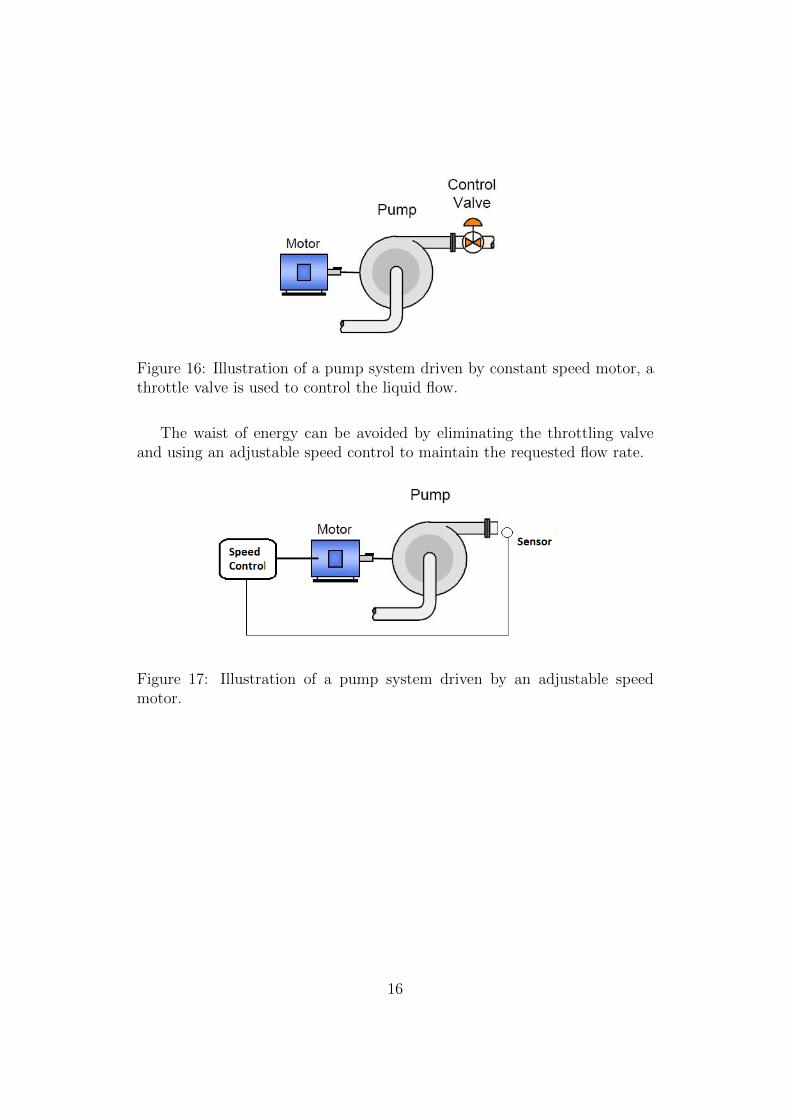
Figure 16: Illustration of a pump system driven by constant speed motor, athrottle valve is used to control the liquid flow.
The waist of energy can be avoided by eliminating the throttling valveand using an adjustable speed control to maintain the requested flow rate.
Figure 17: Illustration of a pump system driven by an adjustable speedmotor.
16

5 Conclusions
� Reviewed the main concepts of sinusoidal PWM technique.
� Reviewed the use of DSP technology in implementing the PWM tech-nique.
� Discussed the energy savings due to use of motor speed control usingtechniques such as PWM and power electronic converters
� Demonstrated how to shape and control the PWM signals to the in-verter switches.
17

6 References
1. N. Mohan, T. M. Undeland, W. P. Robbins, ”Power Electronics. Con-verters, Application and Design”, 2nd ed., Jhon Wiley & Sons
2. Figures number 14 and 16 from http : //en.wikipedia.org/wiki/Adjustable−speed drive
3. Assembly code by Anandarup Das
4. Data sheet of the TMS320F2812 DSP from Texas Instruments’ website(www.ti.com)
18