Northbrook Division - LEADMAN · Northbrook Division 333 Pfingsten Road ... 291 HOU CHU WEI ST ......
56
Northbrook Division 333 Pfingsten Road Northbrook, IL 60062-2096 USA www.ul.com tel: 1 847 272 8800 fax: 1 847 272 8129 Customer service: 1 877 854 3577 A n i n d e p e n d e n t o r g a n i z a t i o n w o r k i n g f o r a s a f e r w o r l d w i t h i n t e g r i t y, p r e c i s i o n a n d k n o w l e d g e. File E252401 Vol 1 Issued 2005-01-24 Revised FOLLOW-UP SERVICE PROCEDURE (TYPE R) DIRECT PLUG-IN AND CORD-CONNECTED CLASS 2 POWER UNITS (EPBU,EPBU7) Manufacturer: SEE ADDENDUM FOR MANUFACTURING LOCATIONS Applicant: COMING DATA CO LTD (125049-001) 291 HOU CHU WEI ST SAN-CHUNG TAIPEI HSIEN TAIWAN Listee: SAME AS APPLICANT (125049-001) This Procedure authorizes the above Manufacturer to use the marking specified by Underwriters Laboratories Inc. only on products covered by this Procedure, in accordance with the applicable Follow-Up Service Agreement. The prescribed Mark or Marking shall be used only at the above manufacturing location on such products which comply with this Procedure and any other applicable requirements. The Procedure contains information for the use of the above named Manufacturer and representatives of Underwriters Laboratories Inc. and is not to be used for any other purpose. It is lent to the Manufacturer with the understanding that it is not to be copied, either wholly or in part, and that it will be returned to Underwriters Laboratories Inc. upon request. This PROCEDURE, and any subsequent revisions, is the property of UNDERWRITERS LABORATORIES INC. and is not transferable. UNDERWRITERS LABORATORIES INC. A.W. Schaefer Sr. Vice President Global Services and Administration N
Transcript of Northbrook Division - LEADMAN · Northbrook Division 333 Pfingsten Road ... 291 HOU CHU WEI ST ......

Northbrook Division 333 Pfingsten Road Northbrook, IL 60062-2096 USA www.ul.com tel: 1 847 272 8800 fax: 1 847 272 8129 Customer service: 1 877 854 3577
A n i n d e p e n d e n t o r g a n i z a t i o n w o r k i n g f o r a s a f e r w o r l d w i t h i n t e g r i t y, p r e c i s i o n a n d k n o w l e d g e.
File E252401 Vol 1 Issued 2005-01-24 Revised FOLLOW-UP SERVICE PROCEDURE (TYPE R) DIRECT PLUG-IN AND CORD-CONNECTED CLASS 2 POWER UNITS (EPBU,EPBU7) Manufacturer: SEE ADDENDUM FOR MANUFACTURING LOCATIONS Applicant: COMING DATA CO LTD (125049-001) 291 HOU CHU WEI ST SAN-CHUNG TAIPEI HSIEN TAIWAN Listee: SAME AS APPLICANT (125049-001) This Procedure authorizes the above Manufacturer to use the marking specified by Underwriters Laboratories Inc. only on products covered by this Procedure, in accordance with the applicable Follow-Up Service Agreement. The prescribed Mark or Marking shall be used only at the above manufacturing location on such products which comply with this Procedure and any other applicable requirements. The Procedure contains information for the use of the above named Manufacturer and representatives of Underwriters Laboratories Inc. and is not to be used for any other purpose. It is lent to the Manufacturer with the understanding that it is not to be copied, either wholly or in part, and that it will be returned to Underwriters Laboratories Inc. upon request. This PROCEDURE, and any subsequent revisions, is the property of UNDERWRITERS LABORATORIES INC. and is not transferable. UNDERWRITERS LABORATORIES INC.
A.W. Schaefer Sr. Vice President Global Services and Administration N
FILE E252401 VOL 1 ADDENDUM TO PAGE 1 ISSUED: 2005-01-24 AUTHORIZATION PAGE REVISED: LOCATION (117647-001) SUN YIH ELECTRONIC CO TU QIAO MANAGEMENT AREA QING XI TOWN DONGGUAN GUANGDONG CHINA (387890-001) KING YES INTERNATIONAL CO LTD SONNGAN PRECINCT QIXI TOWN DONGGUAN GUANGDONG CHINA
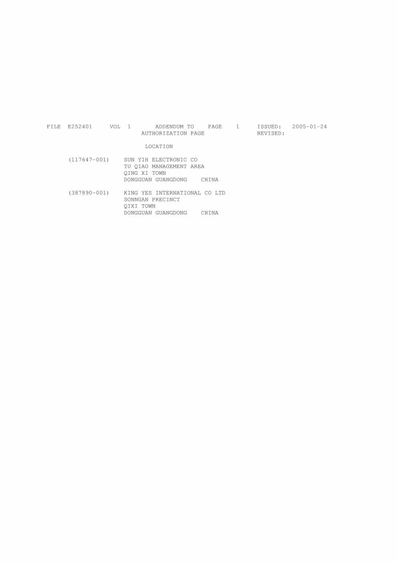
File E252401 Vol. 1 EPBU Page 1 Issued: 5/99 Listing Mark Data Page (LMDP)
(FILE IMMEDIATELY AFTER AUTHORIZATION PAGE)
LISTING MARK
The Listing Mark consists of four elements placed in close proximity and shall appear on Listed products only. Minimum size is not specified, as long as the Listing Mark is legible. The following is suggested.
XXXX = The control number assigned by UL is 24FH .
The minimum height of the registered trademark symbol ® shall be 3/64 of an inch. When the overall diameter of the UL Mark is less than 3/8 of an inch, the trademark symbol may be omitted if it is not legible to the naked eye.
The product identity is: "CLASS 2 POWER SUPPLY", "CLASS 2 TRANSFORMER", or appropriate product identities, as shown in the individual Listing.
The product identity may be omitted if the Mark is directly and permanently applied to the product by stamping, molding, ink-stamping, silk screening or similar process. The product identity may appear elsewhere on the product if the other three elements are part of the nameplate which includes the rating or the catalog or model designation.
Separable Listing Mark (not part of a nameplate and in the form of decals, stickers or labels) will always include the four elements.
The manufacturer may reproduce the Mark or obtain it from a UL authorized supplier.
THIS PAGE IS TO BE REVISED BY FUS DEPARTMENT ONLY
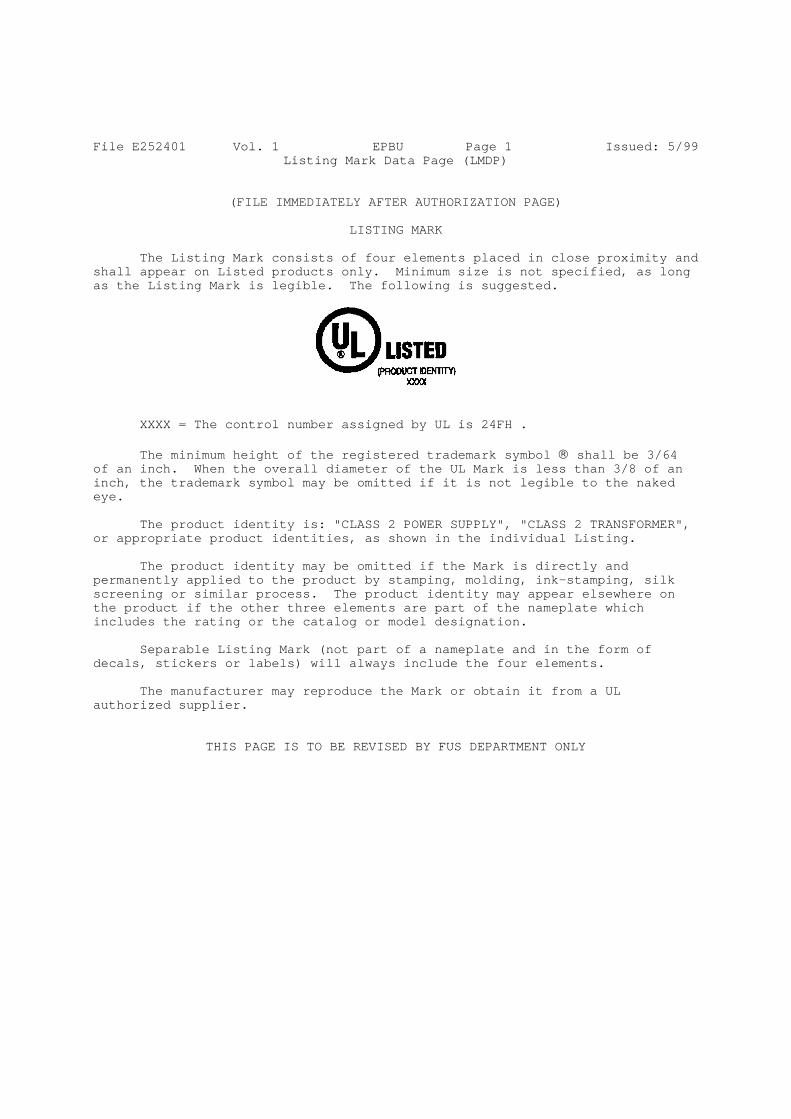
File E252401 Vol. 1 EPBU7 Page 1 Issued: 5/99 Canadian Listing Mark Data Page (CLMDP)
(FILE IMMEDIATELY AFTER AUTHORIZATION PAGE)
LISTING MARK
The Listing Mark consists of four elements placed in close proximity and shall appear on Listed products only. Minimum size is not specified, as long as the Listing Mark is legible. The following is suggested. (If only Canadian coverage is authorized, use only the C-UL Symbol).
UL Symbol to the left and the C-UL Symbol to the right.
Alternatively, the Canadian/US Mark may be used. The UL Symbol with “C” to the left and “US” to the right.
XXXX = The control number assigned by UL is 24FH .
The minimum height of the registered trademark symbol ® shall be 3/64 of an inch. When the overall diameter of the UL Mark is less than 3/8 of an inch, the trademark symbol may be omitted if it is not legible to the naked eye.
The product identity is: "CLASS 2 POWER SUPPLY", or "CLASS 2 TRANSFORMER" or appropriate product identities, as shown in the individual Listing.
The product identity may be omitted if the Mark is directly and permanently applied to the product by stamping, molding, ink-stamping, silk screening or similar process. The product identity may appear elsewhere on the product if the other three elements are part of the nameplate which includes the rating or the catalog or model designation.
Separable Listing Mark (not part of a nameplate and in the form of decals, stickers or labels) will always include the four elements.
The manufacturer may reproduce the Mark or obtain it from a UL authorized supplier.
THIS PAGE IS TO BE REVISED BY FUS DEPARTMENT ONLY
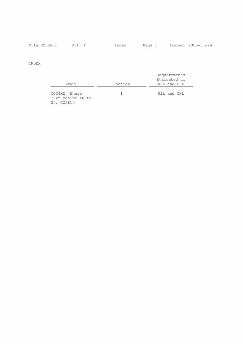
File E252401 Vol. 1 Index Page 1 Issued: 2005-01-24 INDEX
Model Section
Requirements Evaluated to (USL and CNL)
CC24XX, Where “XX” can be 10 to 20, CC3615
1 USL and CNL

File E252401 Project 04CA52487
January 24, 2005
REPORT
On
DIRECT PLUG-IN AND CORD CONNECTED CLASS 2 POWER UNITS
Coming Data Co., Ltd. Taipei, Taiwan
Copyright © 2004 Underwriters Laboratories Inc.
Underwriters Laboratories Inc. authorizes the above named company to reproduce this Report provided it is reproduced in its entirety.

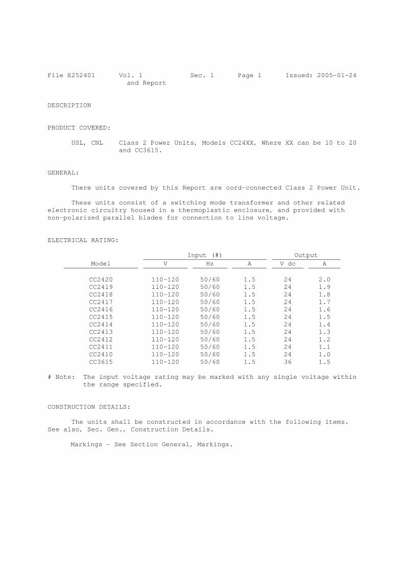
File E252401 Vol. 1 Sec. 1 Page 1 Issued: 2005-01-24 and Report
DESCRIPTION PRODUCT COVERED:
USL, CNL Class 2 Power Units, Models CC24XX, Where XX can be 10 to 20 and CC3615.
GENERAL:
There units covered by this Report are cord-connected Class 2 Power Unit.
These units consist of a switching mode transformer and other related electronic circuitry housed in a thermoplastic enclosure, and provided with non-polarized parallel blades for connection to line voltage. ELECTRICAL RATING:
Input (#) Output Model V Hz A V dc A
CC2420 110-120 50/60 1.5 24 2.0 CC2419 110-120 50/60 1.5 24 1.9 CC2418 110-120 50/60 1.5 24 1.8 CC2417 110-120 50/60 1.5 24 1.7 CC2416 110-120 50/60 1.5 24 1.6 CC2415 110-120 50/60 1.5 24 1.5 CC2414 110-120 50/60 1.5 24 1.4 CC2413 110-120 50/60 1.5 24 1.3 CC2412 110-120 50/60 1.5 24 1.2 CC2411 110-120 50/60 1.5 24 1.1 CC2410 110-120 50/60 1.5 24 1.0 CC3615 110-120 50/60 1.5 36 1.5
# Note: The input voltage rating may be marked with any single voltage within
the range specified. CONSTRUCTION DETAILS:
The units shall be constructed in accordance with the following items. See also, Sec. Gen., Construction Details.
Markings – See Section General, Markings.

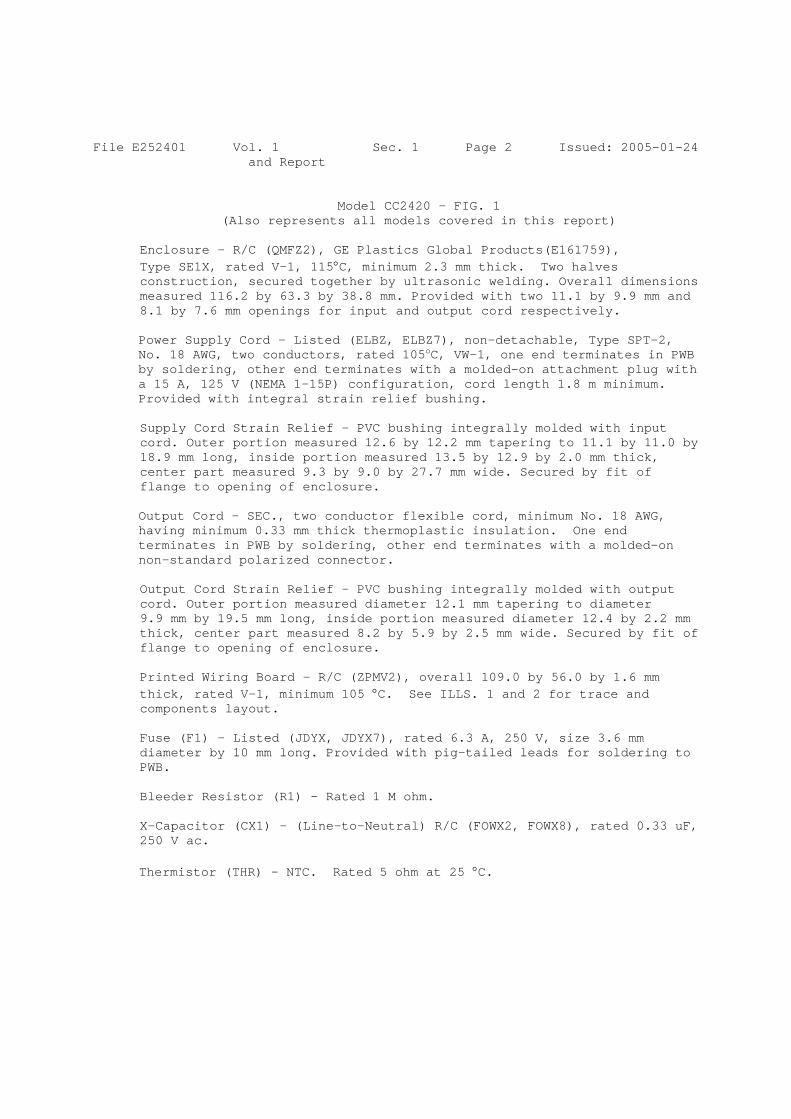
File E252401 Vol. 1 Sec. 1 Page 2 Issued: 2005-01-24 and Report
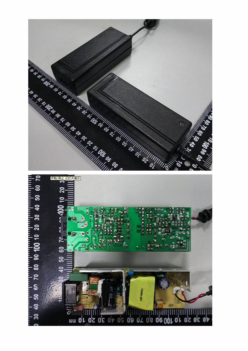
Model CC2420 - FIG. 1 (Also represents all models covered in this report)
Enclosure - R/C (QMFZ2), GE Plastics Global Products(E161759), Type SE1X, rated V-1, 115°C, minimum 2.3 mm thick. Two halves construction, secured together by ultrasonic welding. Overall dimensions measured 116.2 by 63.3 by 38.8 mm. Provided with two 11.1 by 9.9 mm and 8.1 by 7.6 mm openings for input and output cord respectively.
Power Supply Cord – Listed (ELBZ, ELBZ7), non-detachable, Type SPT-2, No. 18 AWG, two conductors, rated 105oC, VW-1, one end terminates in PWB by soldering, other end terminates with a molded-on attachment plug with a 15 A, 125 V (NEMA 1-15P) configuration, cord length 1.8 m minimum. Provided with integral strain relief bushing.
Supply Cord Strain Relief - PVC bushing integrally molded with input cord. Outer portion measured 12.6 by 12.2 mm tapering to 11.1 by 11.0 by 18.9 mm long, inside portion measured 13.5 by 12.9 by 2.0 mm thick, center part measured 9.3 by 9.0 by 27.7 mm wide. Secured by fit of flange to opening of enclosure.
Output Cord – SEC., two conductor flexible cord, minimum No. 18 AWG, having minimum 0.33 mm thick thermoplastic insulation. One end terminates in PWB by soldering, other end terminates with a molded-on non-standard polarized connector.
Output Cord Strain Relief - PVC bushing integrally molded with output cord. Outer portion measured diameter 12.1 mm tapering to diameter 9.9 mm by 19.5 mm long, inside portion measured diameter 12.4 by 2.2 mm thick, center part measured 8.2 by 5.9 by 2.5 mm wide. Secured by fit of flange to opening of enclosure.
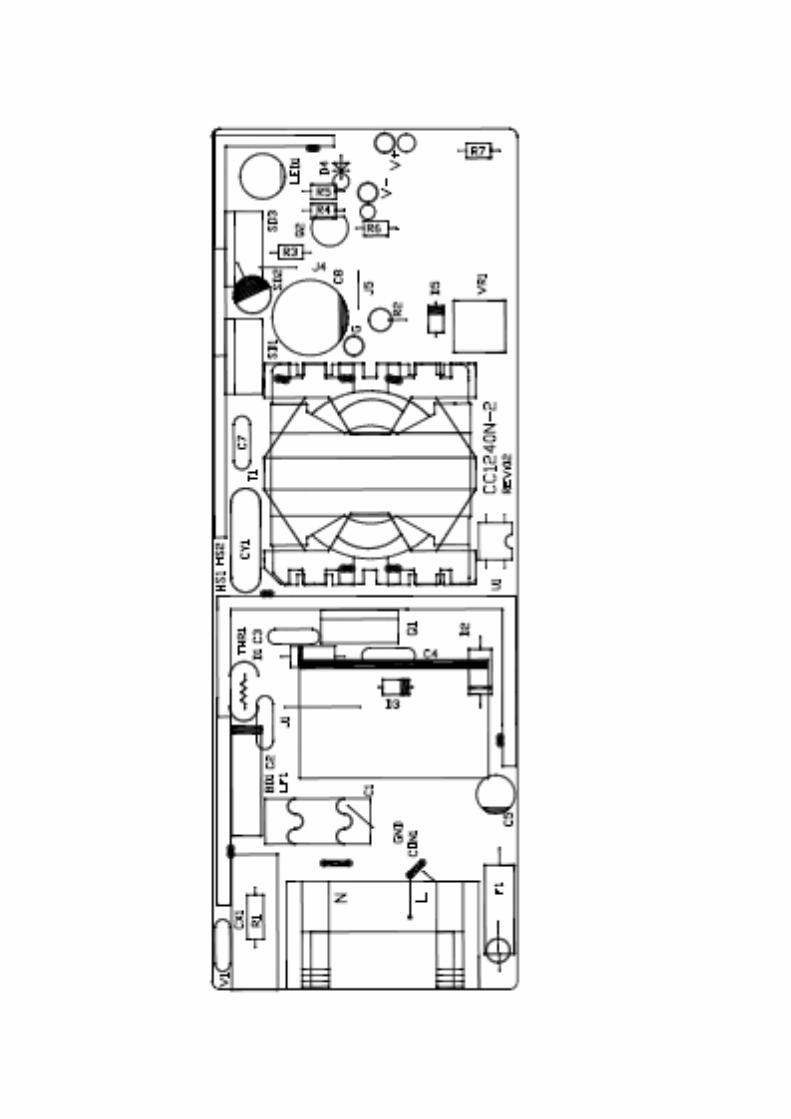
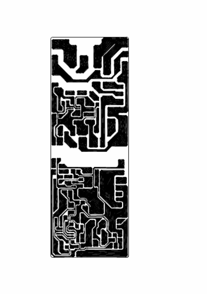
Printed Wiring Board – R/C (ZPMV2), overall 109.0 by 56.0 by 1.6 mm thick, rated V-1, minimum 105 °C. See ILLS. 1 and 2 for trace and components layout.
Fuse (F1) – Listed (JDYX, JDYX7), rated 6.3 A, 250 V, size 3.6 mm diameter by 10 mm long. Provided with pig-tailed leads for soldering to PWB.
Bleeder Resistor (R1) – Rated 1 M ohm.
X-Capacitor (CX1) – (Line-to-Neutral) R/C (FOWX2, FOWX8), rated 0.33 uF, 250 V ac.
Thermistor (THR) - NTC. Rated 5 ohm at 25 °C.

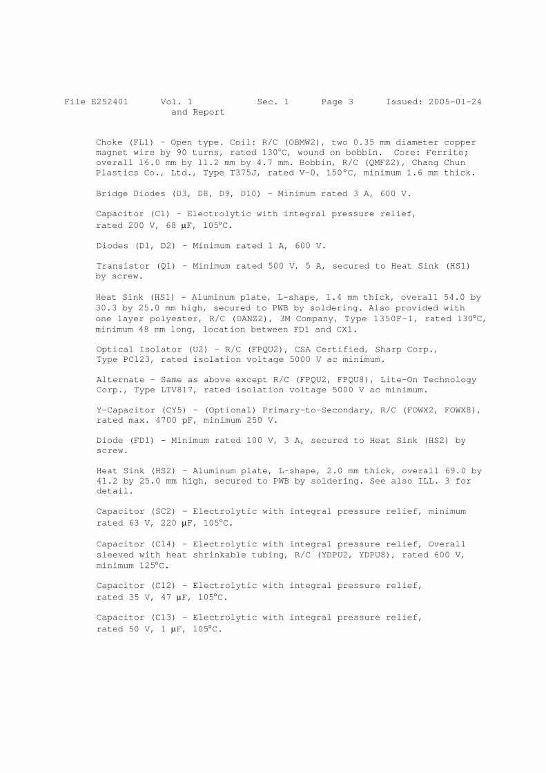
File E252401 Vol. 1 Sec. 1 Page 3 Issued: 2005-01-24 and Report
Choke (FL1) – Open type. Coil: R/C (OBMW2), two 0.35 mm diameter copper magnet wire by 90 turns, rated 130oC, wound on bobbin. Core: Ferrite; overall 16.0 mm by 11.2 mm by 4.7 mm. Bobbin, R/C (QMFZ2), Chang Chun Plastics Co., Ltd., Type T375J, rated V-0, 150°C, minimum 1.6 mm thick.
Bridge Diodes (D3, D8, D9, D10) - Minimum rated 3 A, 600 V.
Capacitor (C1) – Electrolytic with integral pressure relief, rated 200 V, 68 µF, 105°C.
Diodes (D1, D2) – Minimum rated 1 A, 600 V.
Transistor (Q1) – Minimum rated 500 V, 5 A, secured to Heat Sink (HS1) by screw.
Heat Sink (HS1) – Aluminum plate, L-shape, 1.4 mm thick, overall 54.0 by 30.3 by 25.0 mm high, secured to PWB by soldering. Also provided with one layer polyester, R/C (OANZ2), 3M Company, Type 1350F-1, rated 130°C, minimum 48 mm long, location between FD1 and CX1.
Optical Isolator (U2) – R/C (FPQU2), CSA Certified, Sharp Corp., Type PC123, rated isolation voltage 5000 V ac minimum.
Alternate - Same as above except R/C (FPQU2, FPQU8), Lite-On Technology Corp., Type LTV817, rated isolation voltage 5000 V ac minimum.
Y-Capacitor (CY5) – (Optional) Primary-to-Secondary, R/C (FOWX2, FOWX8), rated max. 4700 pF, minimum 250 V.
Diode (FD1) - Minimum rated 100 V, 3 A, secured to Heat Sink (HS2) by screw.
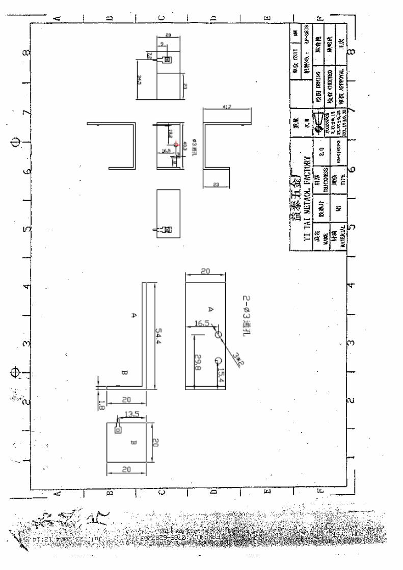
Heat Sink (HS2) – Aluminum plate, L-shape, 2.0 mm thick, overall 69.0 by 41.2 by 25.0 mm high, secured to PWB by soldering. See also ILL. 3 for detail.
Capacitor (SC2) – Electrolytic with integral pressure relief, minimum rated 63 V, 220 µF, 105°C.
Capacitor (C14) – Electrolytic with integral pressure relief, Overall sleeved with heat shrinkable tubing, R/C (YDPU2, YDPU8), rated 600 V, minimum 125°C.
Capacitor (C12) – Electrolytic with integral pressure relief, rated 35 V, 47 µF, 105°C.
Capacitor (C13) – Electrolytic with integral pressure relief, rated 50 V, 1 µF, 105°C.

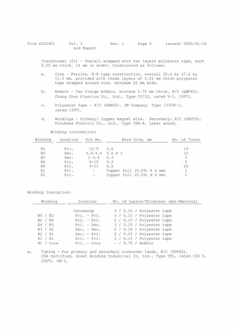
File E252401 Vol. 1 Sec. 1 Page 4 Issued: 2005-01-24 and Report
Transformer (T1) – Overall wrapped with two layers polyester tape, each 0.05 mm thick, 12 mm in width. Constructed as follows:
a. Core – Ferrite, E-E type construction, overall 35.4 by 27.2 by
11.3 mm, provided with three layers of 0.05 mm thick polyester tape wrapped around core, minimum 20 mm wide.
b. Bobbin – Two flange bobbin, minimum 0.75 mm thick, R/C (QMFZ2),
Chang Chun Plastics Co., Ltd., Type T373J, rated V-1, 150°C.
c. Polyester Tape - R/C (OANZ2), 3M Company, Type 1350F-1, rated 130°C.
d. Windings - Primary: Copper magnet wire. Secondary: R/C (OBJT2),
Furukawa Electric Co., Ltd., Type TEX-E, Layer wound.
Winding information:
Winding Insulation:
Winding Location No. of Layers/Thickness (mm)/Material Outerwrap 3 / 0.15 / Polyester tape N5 / E2 Pri. – Pri. 3 / 0.15 / Polyester tape E2 / N4 Pri. – Pri. 2 / 0.10 / Polyester tape E4 / N3 Pri. – Sec. 3 / 0.15 / Polyester tape N3 / E2 Sec. – Sec. 2 / 0.10 / Polyester tape N2 / E1 Sec. – Pri. 2 / 0.10 / Polyester tape E1 / N1 Pri. – Pri. 3 / 0.15 / Polyester tape N1 / Core Pri. - Core - / 0.75 / Bobbin
e. Tubing – For primary and secondary crossover leads. R/C (YDPU2),
CSA Certified, Great Holding Industrial Co. Ltd., Type TFL, rated 150 V, 200°C, VW-1.
Winding Location Pin No. Wire Size, mm No. of Turns
N1 Pri. 12-9 0.6 14 N2 Sec. 5,6-3,4 0.5 X 3 12 N3 Sec. 1-3,4 0.3 5 N4 Pri. 8-10 0.3 5 N5 Pri. 9-11 0.6 26 E1 Pri. - Copper foil (0.05t X 6 mm) 1 E2 Pri. - Copper foil (0.05t X 6 mm) 1

File E252401 Page T1-1 of 1 Issued: 2005-01-24 TEST RECORD NO. 1 GENERAL:
The test results reported relate only to the items tested. SAMPLES:
Samples of Models CC24XX, where “XX” can be 10 to 20 and CC3615 were submitted by the Applicant and subjected to the following tests in accordance with the Standard for Class 2 Power Units, UL 1310, Fourth Edition, with revision dated October 20, 2003 and the Canadian Standard for Power Supplies with Extra Low Voltage Class 2 Outputs, C22.2 No. 223-M91, with revision pages dated June 30, 1991.
Unless otherwise specified, Tests on Models CC2420 and CC3615 were considered to represent Models CC24XX.
The following tests were conducted with acceptable results:
Leakage Current Leakage Current and Dielectric Voltage Withstand after Humidity Maximum Output Voltage Normal Input Maximum Input Output Current and Power Dielectric Withstand after Output Current and Power Full-Load Output Current Normal Temperature Dielectric Voltage Withstand Abnormal Output Loading Dielectric Withstand after Output Loading Transformer Burnout Dielectric Withstand after Transformer Burnout Component Breakdown Dielectric Withstand after Component Breakdown Transformer Insulating Materials Strain Relief Abuse Drop Impact Ball Impact Dielectric Withstand after Drop and Ball Impact Mold Stress Relief Distortion Strain Relief after Mold Stress Relief Distortion
Test methods and results of the above tests have been reviewed and found
to be in accordance with the requirements in the Standard mentioned above.

File E252401 Page C1 Issued: 2005-01-24 CONCLUSION
A sample of the product covered by this Report has been found to comply with the requirements covering the category and the product is judged to be eligible for Listing and Follow-Up Service. The manufacturer is authorized to use the UL Mark on such products which comply with the Follow-Up Service Procedure and any other applicable requirements of Underwriters Laboratories Inc. Only those products which properly bear the UL Mark are considered as Listed by Underwriters Laboratories Inc. Report by: Reviewed by: DERTY CHANG DENNIS LIANG Associate Project Engineer Associate Project Engineer
Any information and documentation provided to you involving UL Mark services are provided on behalf of Underwriters Laboratories Inc.
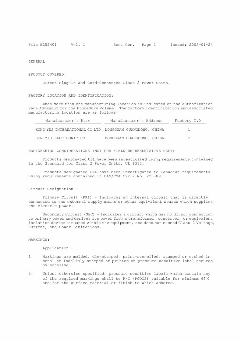
File E252401 Vol. 1 Sec. Gen. Page 1 Issued: 2005-01-24 GENERAL PRODUCT COVERED:
Direct Plug-In and Cord-Connected Class 2 Power Units. FACTORY LOCATION AND IDENTIFICATION:
When more than one manufacturing location is indicated on the Authorization Page Addendum for the Procedure Volume. The factory identification and associated manufacturing location are as follows:
Manufacturer's Name Manufacturer’s Address Factory I.D. KING YES INTERNATIONAL CO LTD DONGGUAN GUANGDONG, CHINA 1 SUN YIH ELECTRONIC CO DONGGUAN GUANGDONG, CHINA 2
ENGINEERING CONSIDERATIONS (NOT FOR FIELD REPRESENTATIVE USE):
Products designated USL have been investigated using requirements contained in the Standard for Class 2 Power Units, UL 1310.
Products designated CNL have been investigated to Canadian requirements using requirements contained in CAN/CSA C22.2 No. 223-M91. Circuit Designation -
Primary Circuit (PRI) - Indicates an internal circuit that is directly connected to the external supply mains or other equivalent source which supplies the electric power.
Secondary Circuit (SEC) - Indicates a circuit which has no direct connection to primary power and derives its power from a transformer, converter, or equivalent isolation device situated within the equipment, and does not exceed Class 2 Voltage, Current, and Power Limitations. MARKINGS:
Application - 1. Markings are molded, die-stamped, paint-stenciled, stamped or etched in
metal or indelibly stamped or printed on pressure-sensitive label secured by adhesive.
2. Unless otherwise specified, pressure sensitive labels which contain any
of the required markings shall be R/C (PGDQ2) suitable for minimum 65°C and for the surface material or finish to which adhered.
File E252401 Vol. 1 Sec. Gen. Page 2 Issued: 2005-01-24
Product Marking - All units shall be marked with the following. 1. Listee's name or File No. “E252401” or trademark as specified in Note 1
below. 2. Model designation. 3. Electrical ratings, including input voltage or voltage range, input
frequency and, if specified in the individual Reports, input amperes, volt-amperes or wattage rating. Additionally, output voltage in ac or dc and output current in amperes, volt-amperes or watts shall be marked, unless the unit is a battery charger marked for use with a specific battery pack.
4. Output polarity (Note 2). 5. Date code (Note 3). 6. Factory identification if applicable. 7. Product Identification and Use. A unit shall be marked with one of the
following terms, as applicable. See individual Reports.
a) "Class 2 Battery Charger," b) "Class 2 Transformer," c) "Class 2 Power Supply," or d) "Class 2 Power Unit."
Note 1: The following marking or trademark may be used to identify the Listee:
(None) Note 2: The polarity of a direct current output shall be plainly marked unless
the unit is provided with a polarized output termination. Note 3: Date Code - Consist of: Example Of Code:
AAYYMMB:
AA : CD YY : Last two digits from the year MM : Month B : May be any number 0 to 9 or letter A to Z or character or blank
8. Cautionary Markings - Shall include the following:
″CAUTION″ and ″Risk of electric shock″ and the following: ″Dry location use only″ or ″Do not expose to liquid, vapor, or rain.″
See also individual Reports.
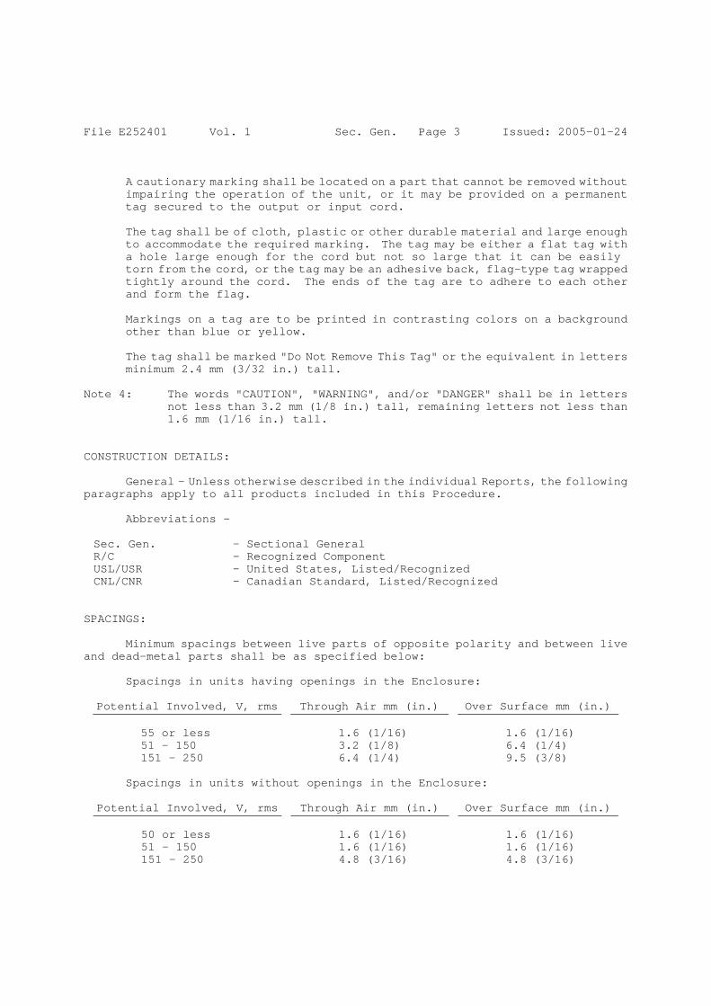
File E252401 Vol. 1 Sec. Gen. Page 3 Issued: 2005-01-24
A cautionary marking shall be located on a part that cannot be removed without impairing the operation of the unit, or it may be provided on a permanent tag secured to the output or input cord.
The tag shall be of cloth, plastic or other durable material and large enough to accommodate the required marking. The tag may be either a flat tag with a hole large enough for the cord but not so large that it can be easily torn from the cord, or the tag may be an adhesive back, flag-type tag wrapped tightly around the cord. The ends of the tag are to adhere to each other and form the flag.
Markings on a tag are to be printed in contrasting colors on a background other than blue or yellow.
The tag shall be marked "Do Not Remove This Tag" or the equivalent in letters minimum 2.4 mm (3/32 in.) tall.
Note 4: The words "CAUTION", "WARNING", and/or "DANGER" shall be in letters
not less than 3.2 mm (1/8 in.) tall, remaining letters not less than 1.6 mm (1/16 in.) tall.
CONSTRUCTION DETAILS:
General - Unless otherwise described in the individual Reports, the following paragraphs apply to all products included in this Procedure.
Abbreviations – Sec. Gen. – Sectional General R/C - Recognized Component USL/USR - United States, Listed/Recognized CNL/CNR - Canadian Standard, Listed/Recognized
SPACINGS:
Minimum spacings between live parts of opposite polarity and between live and dead-metal parts shall be as specified below:
Spacings in units having openings in the Enclosure: Potential Involved, V, rms Through Air mm (in.) Over Surface mm (in.)
55 or less 1.6 (1/16) 1.6 (1/16) 51 – 150 3.2 (1/8) 6.4 (1/4) 151 – 250 6.4 (1/4) 9.5 (3/8)
Spacings in units without openings in the Enclosure:
Potential Involved, V, rms Through Air mm (in.) Over Surface mm (in.)
50 or less 1.6 (1/16) 1.6 (1/16) 51 – 150 1.6 (1/16) 1.6 (1/16) 151 – 250 4.8 (3/16) 4.8 (3/16)
File E252401 Vol. 1 Sec. Gen. Page 4 Issued: 2005-01-24
Segregation - Insulated conductors of different circuits shall be provided with spacings as specified above unless both circuits are insulated for the highest voltage involved. Insulated conductors shall be maintained away from bare live parts of different circuits, sharp edges, and heat producing components by routing or clamping.
Alternate - Segregation may be maintained by use of a barrier. Refer to the individual Reports for details concerning barrier.
Class 2 Secondary Circuit Spacings - Not specified as spacings are based on Dielectric Withstand Tests.
Blades - Folded over or solid, copper, brass or bronze. Located minimum 8.0 mm from edge of enclosure. See Sec. Gen., ILL. 1 for dimensions, spacing and relative location of blades.
Printed Wiring Boards - Unless designated as "SEC", all printed wiring boards (PWB), shall be R/C (ZPMV2) with a minimum flammability rating of V-2 for units without openings, V-1 for units with openings, and have a minimum operating temperature rating of 90°C. Also, the solder time and temperature of any wave soldering machines shall not exceed the values indicated in the Component Recognition Report or Directory. Hand soldered boards shall be examined for charring, burned areas or other damage.
See also the individual Reports for additional requirements or instructions that may supersede these instructions.
Internal Wiring - Unless otherwise specified, internal wiring shall be R/C (AVLV2) with insulation rated 300 V, 80°C minimum.
Electrical Connections - Electrical connections may be accomplished by soldering or use of wire connectors.
Wire connectors or terminals, shall be Listed or Recognized (ZMVV2), suitable for the type, size and number of conductors and applied using the tool recommended by the connector manufacturer. Additionally, terminals shall be of the closed loop, or spade type with upturned ends.
Quick connect terminals shall be Listed with integral detent or locking type, suitable for the type, size and number of conductors and applied using the tool recommended by the connector manufacturer.
Solder connections shall be mechanically secured prior to soldering. Printed wiring assemblies may be wave soldered.
Insulation Tubing/Sleeving - R/C (YDPU2)/CSA Certified; (YDRY2)/CSA Certified; (YDTU2)/CSA Certified; (UZFT2) or (UZKX2)/CSA Certified, rated minimum 90°C, 300 V.

File E252401 Vol. 1 Sec. Gen. Page 5 Issued: 2005-01-24
Wire Positioning Devices - Unless otherwise specified, R/C (ZODZ2)/CSA Certified, rated minimum 60°C.
Corrosion Protection - Iron and steel parts shall be protected against corrosion by painting, plating, galvanizing or enameling.
Exception: Laminations and small parts of iron or steel such as washers or screws that are not current carrying parts do not require corrosion protection.
STANDARD APPENDIX PAGE (SAP). TO BE REVISED BY CONTROLLING OFFICE ONLY.
App. A Page 1 Issued: 11-1-95 Direct Plug-In and Cord-Connected Class 2 Power Units (EPBU, EPBU2)
OUTLINE OF STANDARDIZED APPENDIX PAGES I APPENDIX A - UL Representative's Duties and Instructions for Examination
of the Product A) UL Representative's Duties 1 B) Special Requirements 1) Dielectric Voltage Withstand Test Equipment 2 2) Grounding Continuity 3 3) Power Supply Cords 3 II APPENDIX B - Reserved For Future Use III APPENDIX C - Reserved For Future Use IV APPENDIX D - Manufacturer's Responsibilities and Requirements for Factory Tests A) Manufacturer's Responsibilities 1 B) Requirements for Factory Tests 3 (1) Production-Line Dielectric Voltage- Withstand Test 3 (2) Production-Line Grounding Continuity Test 7
COPYRIGHT © 1995 UNDERWRITERS LABORATORIES INC.
STANDARD APPENDIX PAGE (SAP). TO BE REVISED BY CONTROLLING OFFICE ONLY.
App. A Page 2 Issued: 11-1-95 Direct Plug-In and Cord-Connected Class 2 Power Units (EPBU, EPBU2)
A P P E N D I X A
INSTRUCTIONS TO THE UL REPRESENTATIVE FOR EXAMINATION OF PRODUCT
UL REPRESENTATIVE'S DUTIES The UL Representative's duties include, but are not limited to: Examining the construction of the product intended to bear the UL Mark or Marking to determine compliance with the description of the product and any other requirements expressed in this Procedure. Selecting samples, where so specified by Appendix B, for shipment to UL for follow-up tests. Inspecting the test records and facilities of the manufacturer, where so specified by Appendix D, to ensure that: A. The proper number of samples are undergoing the required tests; B. The required tests are being performed correctly; C. The proper information is being recorded and is up-to-date; and D. The instruments being used for the tests have been calibrated at the
prescribed interval and function properly. PROCEDURE IN CASE OF NONCONFORMANCE Report to the manufacturer and Follow-Up Services Department by means of a Variation Notice (VN) if: A. Variations in construction are found; B. The manufacturer's method and/or frequency of testing is not as
described; C. The test records maintained by the manufacturer are not as
described; D. The manufacturer's inspection program is not being performed as
described; or
STANDARD APPENDIX PAGE (SAP). TO BE REVISED BY CONTROLLING OFFICE ONLY.
App. A Page 3 Issued: 11-1-95 Direct Plug-In and Cord-Connected Class 2 Power Units (EPBU, EPBU2) E. Nonconforming test results are witnessed during tests conducted
specifically for the UL Representative.
STANDARD APPENDIX PAGE (SAP). TO BE REVISED BY CONTROLLING OFFICE ONLY.
App. A Page 4 Issued: 11-1-95 Direct Plug-In and Cord-Connected Class 2 Power Units (EPBU, EPBU2) Explain to the manufacturer that a Variation Notice is a means of communication with the manufacturer and forms a record of those items where nonconformance to the Procedure has been found. When a product does not conform with the Follow-Up Services Procedure, and the UL Representative cannot determine if the variation is acceptable, require that the manufacturer shall: A. Remove any markings referencing UL from the product, B. Suitably modify all products that do not comply with the Follow-Up
Services Procedure, or C. Hold shipment pending further instructions from Follow-Up Services. In the event of a disagreement between the manufacturer and the UL Representative as to whether a product is acceptable, the manufacturer shall hold production at the factory pending resolution of the variations. The manufacturer has the right to disagree and appeal the decision; and the UL Representative shall provide the name of the Follow-Up Services engineer to whom the appeal is to be made. Should Follow-Up Services grant temporary authorization for the continued use of the UL Mark, such temporary authorization shall only be for the time needed to review and/or process the Procedure revisions, or as otherwise specified to cover a particular lot or production run. INSTRUCTIONS FOR EXAMINATION OF THE PRODUCT At each inspection, samples of current production and/or stock shall be examined for compliance with the applicable descriptions and requirements contained in this Procedure. In making this determination, consideration shall also be given to the following special requirements applying to the products covered by this Procedure. SPECIAL REQUIREMENTS: Special requirements which may also apply to some or all of the products covered by this Procedure include the following: 1. Dielectric Voltage-Withstand Test Equipment The Dielectric Voltage-Withstand Test equipment shall be as specified on
Page 8, Appendix D, titled Test Equipment. If
STANDARD APPENDIX PAGE (SAP). TO BE REVISED BY CONTROLLING OFFICE ONLY.
App. A Page 5 Issued: 11-1-95 Direct Plug-In and Cord-Connected Class 2 Power Units (EPBU, EPBU2)
the Dielectric Voltage-Withstand Test Equipment in use is not as specified, then the UL Representative should verify that it has the features as outlined in Appendix D.
STANDARD APPENDIX PAGE (SAP). TO BE REVISED BY CONTROLLING OFFICE ONLY.
App. A Page 6 Issued: 11-1-95 Direct Plug-In and Cord-Connected Class 2 Power Units (EPBU, EPBU2) 2. Grounding Continuity Test Equipment The grounding continuity test equipment shall be as specified on Page 7,
Appendix D. 3. Power Supply Cords Non-Detachable Power Supply Cord - A non-detachable power supply cord as described in the individual sections
of the Procedure must be provided and shipped with the unit in all cases. The power supply cord and any alternatives must be described in each Procedure section or Section General.
Detachable Power Supply Cord - The detachable power supply cord as described in the individual sections
of the Procedure may or may not be shipped with the unit. Please use the guidelines in Table 1 in assisting the manufacturer to apply the alternatives under each of the situations described in the notes to Table 1. Table 1 also includes alternative detachable power supply cords which may be shipped with units intended for use outside the USA.

STANDARD APPENDIX PAGE (SAP). TO BE REVISED BY CONTROLLING OFFICE ONLY.
App. A Page 7 Issued: 11-1-95 Direct Plug-In and Cord-Connected Class 2 Power Units (EPBU, EPBU2)
TABLE 1 - DETACHABLE POWER SUPPLY CORD REQUIREMENTS The requirements for detachable power supply cords depend on whether the cord is provided. This table, along with the following notes, details the requirements for each of the possible situations.
Status of Detachable Power Cord
Provided Not Provided
Note A or D (Notes B and C) or (Notes B and E)
NOTE: A. The power supply cord should be as described in the Procedure section. B. A marking must be provided adjacent to the appliance coupler or at an equivalent location either to inform the user on proper selection of the power supply cord or to see the instruction manual for this information. This marking may be in the form of a tag, nonpermanent label, or product insert that is provided on or packaged with the product so that the marking is visible at the time of installation. C. The marking (tag, label, or product insert) or instruction manual must contain complete instructions concerning selection of the proper power supply cord. The reference to the power supply cord must be of a UL Listed detachable power supply cord consisting of the specific configuration of appliance coupler, the cord type, and the electrical rating of the power supply cord as described in the appropriate sections of the Procedure. Please refer to Table 2 for equivalent types of cords.
STANDARD APPENDIX PAGE (SAP). TO BE REVISED BY CONTROLLING OFFICE ONLY.
App. A Page 8 Issued: 11-1-95 Direct Plug-In and Cord-Connected Class 2 Power Units (EPBU, EPBU2)
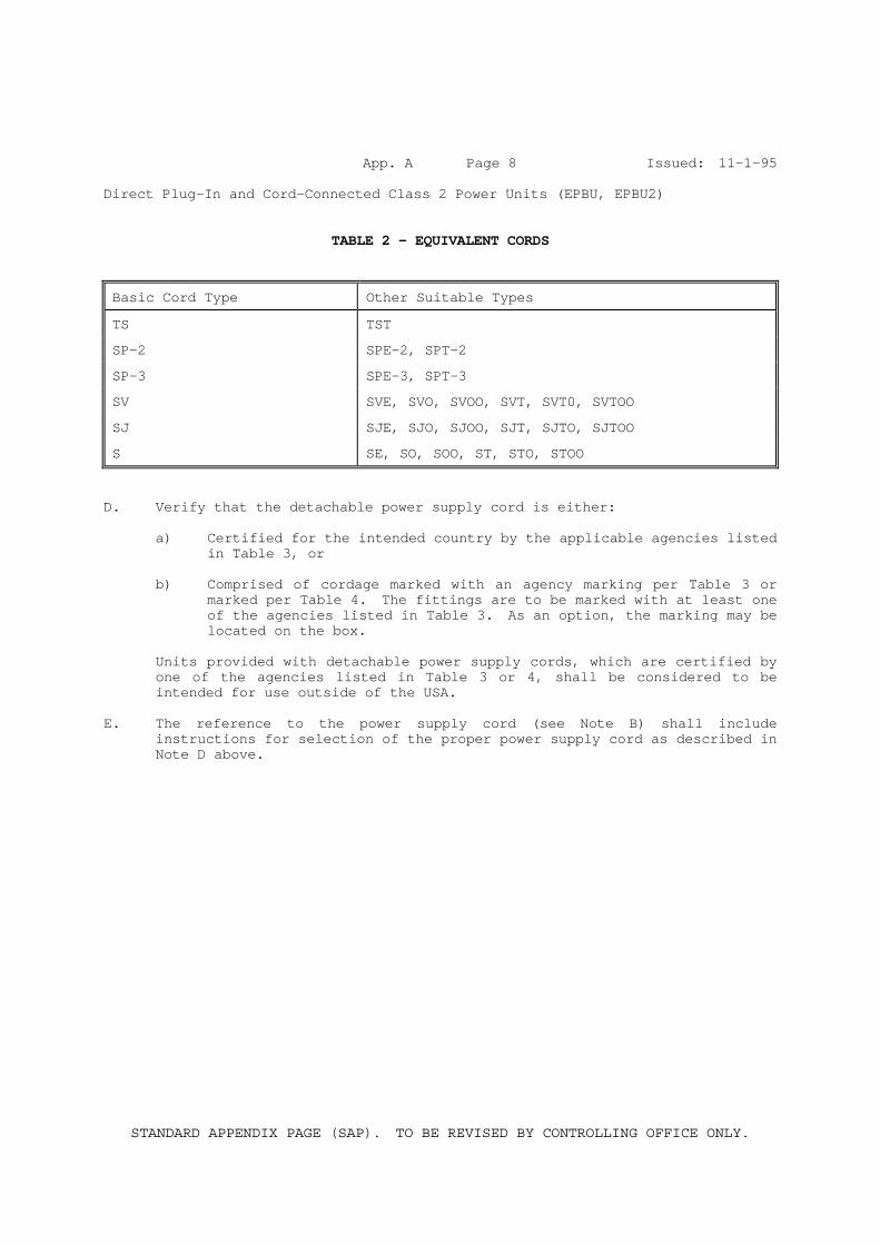
TABLE 2 - EQUIVALENT CORDS
Basic Cord Type Other Suitable Types
TS TST
SP-2 SPE-2, SPT-2
SP-3 SPE-3, SPT-3
SV SVE, SVO, SVOO, SVT, SVT0, SVTOO
SJ SJE, SJO, SJOO, SJT, SJTO, SJTOO
S SE, SO, SOO, ST, STO, STOO
D. Verify that the detachable power supply cord is either: a) Certified for the intended country by the applicable agencies listed
in Table 3, or b) Comprised of cordage marked with an agency marking per Table 3 or
marked per Table 4. The fittings are to be marked with at least one of the agencies listed in Table 3. As an option, the marking may be located on the box.
Units provided with detachable power supply cords, which are certified by
one of the agencies listed in Table 3 or 4, shall be considered to be intended for use outside of the USA.
E. The reference to the power supply cord (see Note B) shall include
instructions for selection of the proper power supply cord as described in Note D above.
STANDARD APPENDIX PAGE (SAP). TO BE REVISED BY CONTROLLING OFFICE ONLY.
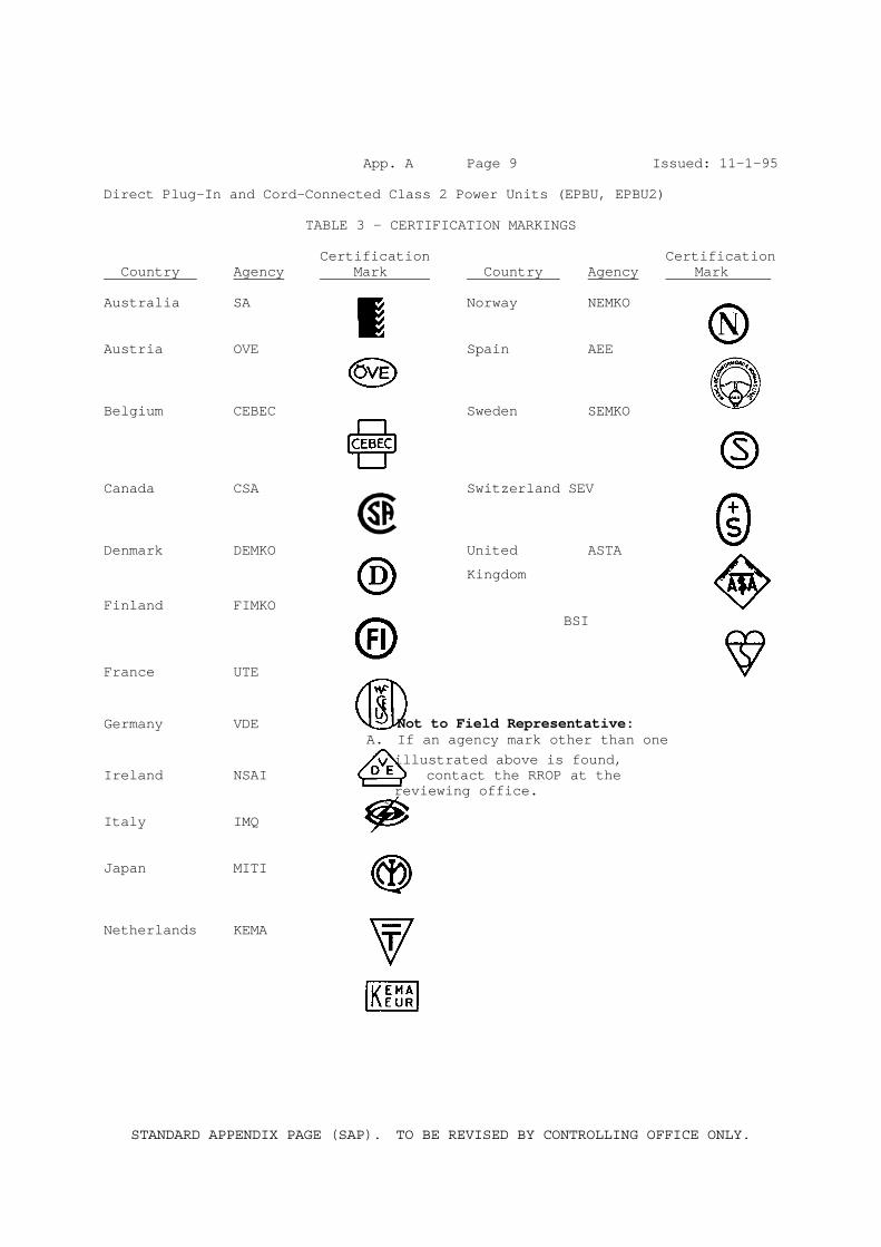
App. A Page 9 Issued: 11-1-95 Direct Plug-In and Cord-Connected Class 2 Power Units (EPBU, EPBU2)
TABLE 3 - CERTIFICATION MARKINGS Certification Certification Country Agency Mark Country Agency Mark Australia SA Norway NEMKO Austria OVE Spain AEE Belgium CEBEC Sweden SEMKO Canada CSA Switzerland SEV Denmark DEMKO United ASTA
Kingdom
Finland FIMKO BSI France UTE
Germany VDE Not to Field Representative: A. If an agency mark other than one illustrated above is found, Ireland NSAI contact the RROP at the reviewing office. Italy IMQ Japan MITI Netherlands KEMA
STANDARD APPENDIX PAGE (SAP). TO BE REVISED BY CONTROLLING OFFICE ONLY.
App. A Page 10 Issued: 11-1-95 Direct Plug-In and Cord-Connected Class 2 Power Units (EPBU, EPBU2)
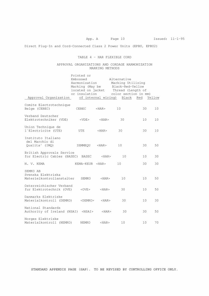
TABLE 4 - HAR FLEXIBLE CORD
APPROVAL ORGANIZATIONS AND CORDAGE HARMONIZATION MARKING METHODS
Printed or Embossed Alternative Harmonization Marking Utilizing Marking (May be Black-Red-Yellow located on jacket Thread (Length of or insulation color section in mm) Approval Organization of internal wiring) Black Red Yellow Comite Electrotechnique Belge (CEBEC) CEBEC <HAR> 10 30 10 Verband Deutscher Elektrotechniker (VDE) <VDE> <HAR> 30 10 10 Union Technique de 1`Electricite (UTE) UTE <HAR> 30 30 10 Instituto Italiano del Marchio di Qualita' (IMQ) IEMMEQU <HAR> 10 30 50 British Approvals Service for Electric Cables (BASEC) BASEC <HAR> 10 10 30 N. V. KEMA KEMA-KEUR <HAR> 10 30 30 SEMKO AB Svenska Elektriska Materielkontrollanstalter SEMKO <HAR> 10 10 50 Osterreichischer Verband fur Elektrotechnik (OVE) <OVE> <HAR> 30 10 50 Danmarks Elektriske Materialkontroll (DEMKO) <DEMKO> <HAR> 30 10 30 National Standards Authority of Ireland (NSAI) <NSAI> <HAR> 30 30 50 Norges Elektriske Materialkontroll (NEMKO) NEMKO <HAR> 10 10 70
STANDARD APPENDIX PAGE (SAP). TO BE REVISED BY CONTROLLING OFFICE ONLY.
App. A Page 11 Issued: 11-1-95 Direct Plug-In and Cord-Connected Class 2 Power Units (EPBU, EPBU2)
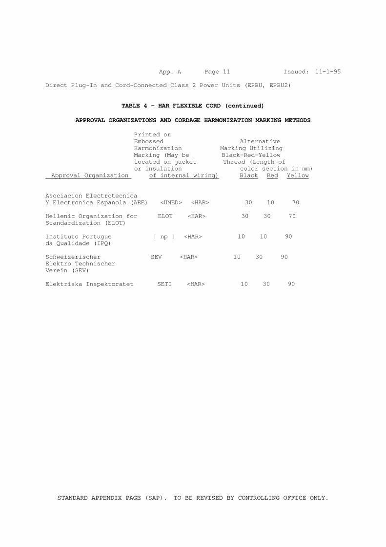
TABLE 4 - HAR FLEXIBLE CORD (continued)
APPROVAL ORGANIZATIONS AND CORDAGE HARMONIZATION MARKING METHODS Printed or Embossed Alternative Harmonization Marking Utilizing Marking (May be Black-Red-Yellow located on jacket Thread (Length of or insulation color section in mm) Approval Organization of internal wiring) Black Red Yellow Asociacion Electrotecnica Y Electronica Espanola (AEE) <UNED> <HAR> 30 10 70 Hellenic Organization for ELOT <HAR> 30 30 70 Standardization (ELOT) Instituto Portugue | np | <HAR> 10 10 90 da Qualidade (IPQ) Schweizerischer SEV <HAR> 10 30 90 Elektro Technischer Verein (SEV) Elektriska Inspektoratet SETI <HAR> 10 30 90

STANDARD APPENDIX PAGE (SAP). TO BE REVISED BY CONTROLLING OFFICE ONLY.
App. B Page 1 Issued: 11-1-95 Direct Plug-In and Cord-Connected Class 2 Power Units (EPBU, EPBU2)
A P P E N D I X B
RESERVED FOR FUTURE USE
STANDARD APPENDIX PAGE (SAP). TO BE REVISED BY CONTROLLING OFFICE ONLY.
App. C Page 1 Issued: 11-1-95 Direct Plug-In and Cord-Connected Class 2 Power Units (EPBU, EPBU2)
A P P E N D I X C
RESERVED FOR FUTURE USE
STANDARD APPENDIX PAGE (SAP). TO BE REVISED BY CONTROLLING OFFICE ONLY.
App. D Page 1 Issued: 11-1-95 Direct Plug-In and Cord-Connected Class 2 Power Units (EPBU, EPBU2)
A P P E N D I X D
MANUFACTURER'S RESPONSIBILITIES AND REQUIREMENTS FOR FACTORY TESTS
MANUFACTURER'S RESPONSIBILITIES: The manufacturer's responsibilities include, but are not limited to: 1. Control of UL Mark - Restrict the use of markings that reference UL
(either directly or by use of the name, an abbreviation of it, or the UL symbol, or indirectly by means of agreed-upon markings that are understood to indicate acceptance by UL) to those products that are found by the manufacturer's own inspection to comply with the Follow-Up Service Procedure description. Use of such markings is further limited by the agreements that have been executed by the subscriber and UL.
2. Substitution of Plastic Materials - The product description may require
use of a Recognized Component Plastic with a minimum flammability rating. For these cases, before a plastic material may be used, the current edition of the Recognized Component Directory and Supplement, a copy of the Plastic Material Company's Recognition Report, or a copy of the Component Recognition Card shall be checked to insure that the plastic material has a flammability rating as specified at the thickness specified. The Component Recognition Report or Cardtext may be used only if it is issued after the latest publication of the Recognized Component Directory. A copy of the current edition of the Recognized Component Directory and Supplement should be checked to insure that all vendors still have UL Recognition. If a plastic material is not in the Recognized Component Directory or Supplement, a copy of the Recognition Report should be made available to the manufacturer by the vendor.
In all cases where the information is not available in the Recognized Component Directory or Supplement, it is the manufacturer's responsibility to provide the UL Representative with either a copy of the Plastic Material Recognition Report, or Component Recognition Card so that the UL Representative can determine the flammability rating and minimum thickness of the plastic material being used.
NOTE: This does not apply to materials for which the specific manufacturer and type designation of the plastic is described in the Procedure (i.e. Enclosures).
STANDARD APPENDIX PAGE (SAP). TO BE REVISED BY CONTROLLING OFFICE ONLY.
App. D Page 2 Issued: 11-1-95 Direct Plug-In and Cord-Connected Class 2 Power Units (EPBU, EPBU2) 3. Substitution of Non-Specified PWB's - Before a printed wiring board may be
used, the current edition of the Recognized Component Directory, the Supplement, a copy of the printed wiring board company's Recognition Report or a copy of the Component Recognition (Yellow) Card must be checked to ensure that the solder temperature and time is as indicated and that the printed wiring board has flammability and operating temperature rating as specified in the Section General or in the individual Section description.
4. Production-Line Tests - Conduct the Factory Tests detailed in Appendix D. 5. Test Equipment Calibration - Determine that the test equipment is
functioning properly and that it is calibrated at least annually, or whenever it has been subject to abuse (such as being dropped or struck with an object) or its accuracy is questionable. Calibration may be by the manufacturer or an outside laboratory. In either case, it shall be by comparison with a Standard that is traceable to the applicable U.S. or the appropriate country's National Standard. Certification of calibration shall be maintained by the manufacturer until the next succeeding certification, and shall be readily available for review by the UL Representative. A letter from the outside laboratory or from an off-site manufacturer's calibration lab stating that their lab standards are directly traceable to their country's National Standard and outlining their traceability pathway is considered adequate proof of traceability.
6. Packaging - There shall be no marking on the carton or package that is, or
could be construed to be, in conflict or an extension of the use covered in the instruction manual or Procedure.
7. Product Variations - In the event that a nonconformance to the Procedure
is found, a Variation Notice will be issued. A Variation Notice is a means of communication with the applicant and manufacturer, and forms a record of those items where nonconformance to the Procedure has been found.
When a product does not comply with the Follow-Up Services Procedure, the
manufacturer shall either:
A. Remove any markings referencing UL from the product, packaging, instructions, etc., or
B. Suitably modify all products that do not comply with the Follow-Up
Services Procedure, or
C. Hold shipment pending further instructions from Follow-up Services.
STANDARD APPENDIX PAGE (SAP). TO BE REVISED BY CONTROLLING OFFICE ONLY.
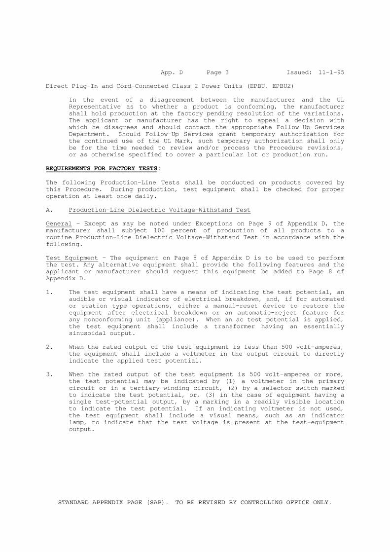
App. D Page 3 Issued: 11-1-95 Direct Plug-In and Cord-Connected Class 2 Power Units (EPBU, EPBU2) In the event of a disagreement between the manufacturer and the UL
Representative as to whether a product is conforming, the manufacturer shall hold production at the factory pending resolution of the variations. The applicant or manufacturer has the right to appeal a decision with which he disagrees and should contact the appropriate Follow-Up Services Department. Should Follow-Up Services grant temporary authorization for the continued use of the UL Mark, such temporary authorization shall only be for the time needed to review and/or process the Procedure revisions, or as otherwise specified to cover a particular lot or production run.
REQUIREMENTS FOR FACTORY TESTS: The following Production-Line Tests shall be conducted on products covered by this Procedure. During production, test equipment shall be checked for proper operation at least once daily. A. Production-Line Dielectric Voltage-Withstand Test General - Except as may be noted under Exceptions on Page 9 of Appendix D, the manufacturer shall subject 100 percent of production of all products to a routine Production-Line Dielectric Voltage-Withstand Test in accordance with the following. Test Equipment - The equipment on Page 8 of Appendix D is to be used to perform the test. Any alternative equipment shall provide the following features and the applicant or manufacturer should request this equipment be added to Page 8 of Appendix D. 1. The test equipment shall have a means of indicating the test potential, an
audible or visual indicator of electrical breakdown, and, if for automated or station type operations, either a manual-reset device to restore the equipment after electrical breakdown or an automatic-reject feature for any nonconforming unit (appliance). When an ac test potential is applied, the test equipment shall include a transformer having an essentially sinusoidal output.
2. When the rated output of the test equipment is less than 500 volt-amperes,
the equipment shall include a voltmeter in the output circuit to directly indicate the applied test potential.
3. When the rated output of the test equipment is 500 volt-amperes or more,
the test potential may be indicated by (1) a voltmeter in the primary circuit or in a tertiary-winding circuit, (2) by a selector switch marked to indicate the test potential, or, (3) in the case of equipment having a single test-potential output, by a marking in a readily visible location to indicate the test potential. If an indicating voltmeter is not used, the test equipment shall include a visual means, such as an indicator lamp, to indicate that the test voltage is present at the test-equipment output.
STANDARD APPENDIX PAGE (SAP). TO BE REVISED BY CONTROLLING OFFICE ONLY.
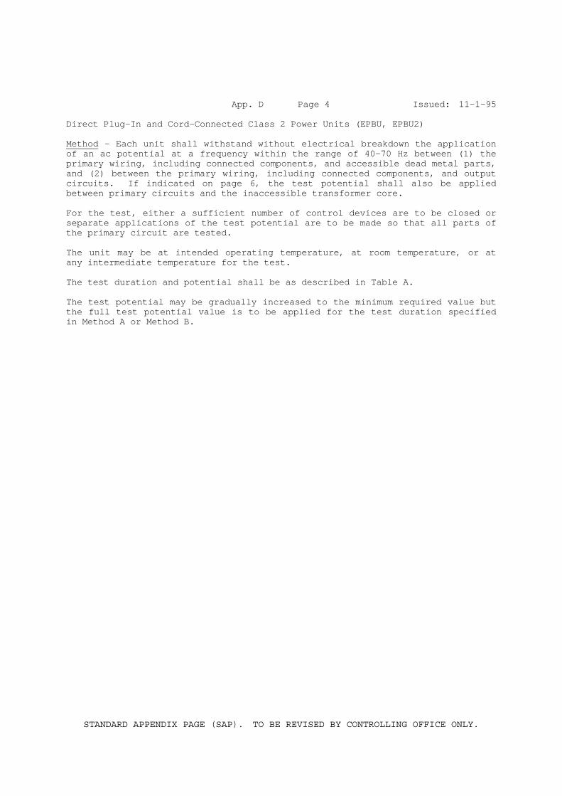
App. D Page 4 Issued: 11-1-95 Direct Plug-In and Cord-Connected Class 2 Power Units (EPBU, EPBU2) Method - Each unit shall withstand without electrical breakdown the application of an ac potential at a frequency within the range of 40-70 Hz between (1) the primary wiring, including connected components, and accessible dead metal parts, and (2) between the primary wiring, including connected components, and output circuits. If indicated on page 6, the test potential shall also be applied between primary circuits and the inaccessible transformer core. For the test, either a sufficient number of control devices are to be closed or separate applications of the test potential are to be made so that all parts of the primary circuit are tested. The unit may be at intended operating temperature, at room temperature, or at any intermediate temperature for the test. The test duration and potential shall be as described in Table A. The test potential may be gradually increased to the minimum required value but the full test potential value is to be applied for the test duration specified in Method A or Method B.
STANDARD APPENDIX PAGE (SAP). TO BE REVISED BY CONTROLLING OFFICE ONLY.
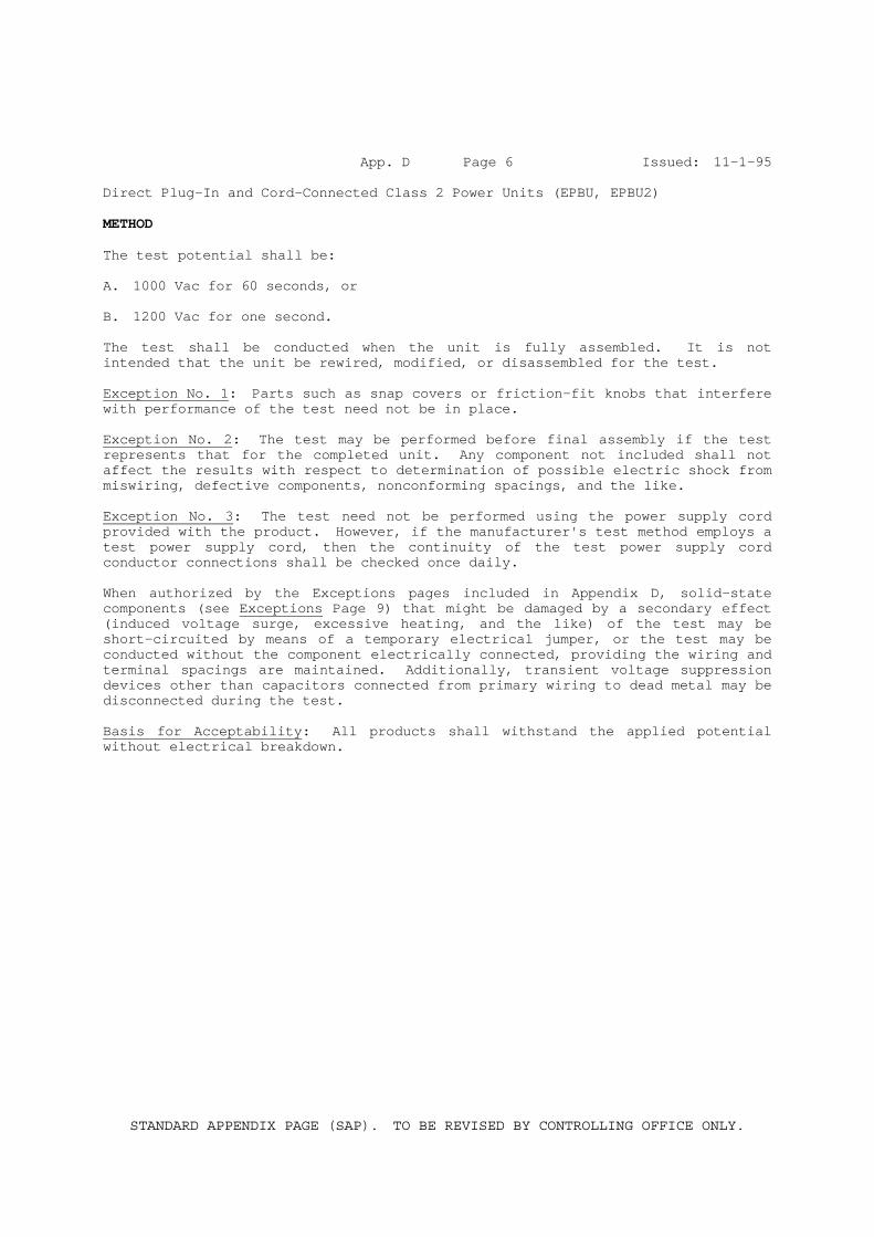
App. D Page 6 Issued: 11-1-95 Direct Plug-In and Cord-Connected Class 2 Power Units (EPBU, EPBU2) METHOD The test potential shall be: A. 1000 Vac for 60 seconds, or B. 1200 Vac for one second. The test shall be conducted when the unit is fully assembled. It is not intended that the unit be rewired, modified, or disassembled for the test. Exception No. 1: Parts such as snap covers or friction-fit knobs that interfere with performance of the test need not be in place. Exception No. 2: The test may be performed before final assembly if the test represents that for the completed unit. Any component not included shall not affect the results with respect to determination of possible electric shock from miswiring, defective components, nonconforming spacings, and the like. Exception No. 3: The test need not be performed using the power supply cord provided with the product. However, if the manufacturer's test method employs a test power supply cord, then the continuity of the test power supply cord conductor connections shall be checked once daily. When authorized by the Exceptions pages included in Appendix D, solid-state components (see Exceptions Page 9) that might be damaged by a secondary effect (induced voltage surge, excessive heating, and the like) of the test may be short-circuited by means of a temporary electrical jumper, or the test may be conducted without the component electrically connected, providing the wiring and terminal spacings are maintained. Additionally, transient voltage suppression devices other than capacitors connected from primary wiring to dead metal may be disconnected during the test. Basis for Acceptability: All products shall withstand the applied potential without electrical breakdown.
STANDARD APPENDIX PAGE (SAP). TO BE REVISED BY CONTROLLING OFFICE ONLY.
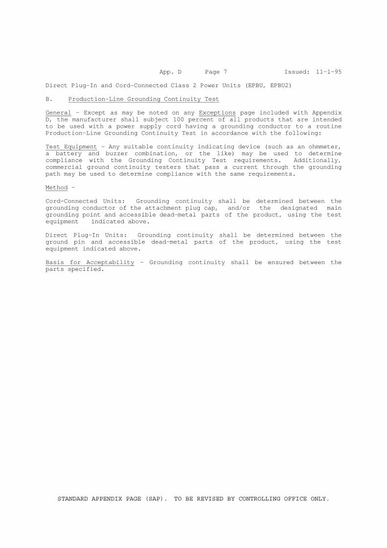
App. D Page 7 Issued: 11-1-95 Direct Plug-In and Cord-Connected Class 2 Power Units (EPBU, EPBU2) B. Production-Line Grounding Continuity Test General - Except as may be noted on any Exceptions page included with Appendix D, the manufacturer shall subject 100 percent of all products that are intended to be used with a power supply cord having a grounding conductor to a routine Production-Line Grounding Continuity Test in accordance with the following: Test Equipment - Any suitable continuity indicating device (such as an ohmmeter, a battery and buzzer combination, or the like) may be used to determine compliance with the Grounding Continuity Test requirements. Additionally, commercial ground continuity testers that pass a current through the grounding path may be used to determine compliance with the same requirements. Method - Cord-Connected Units: Grounding continuity shall be determined between the grounding conductor of the attachment plug cap, and/or the designated main grounding point and accessible dead-metal parts of the product, using the test equipment indicated above. Direct Plug-In Units: Grounding continuity shall be determined between the ground pin and accessible dead-metal parts of the product, using the test equipment indicated above. Basis for Acceptability - Grounding continuity shall be ensured between the parts specified.

File E252401 Vol. 1 App. D Page 5 Issued: 1995-11-01 New: 2005-01-24
Direct Plug-In and Cord-Connected Class 2 Power Units (EPBU, EPBU2)
PRODUCTS WHICH REQUIRES PRODUCTION DIELECTRIC TEST BETWEEN PRIMARY CIRCUIT PARTS AND INACCESSIBLE TRANSFORMER CORE
(see Method, Page 4)
Product Designation Procedure Section or Date

File E252401 Vol. 1 App. D Page 8 Issued: 1995-11-01 New: 2005-01-24
Direct Plug-In and Cord-Connected Class 2 Power Units (EPBU, EPBU2)
Test Equipment
Production-Line Dielectric Voltage-Withstand Test - The manufacturer may use the equipment listed below for this test. See Appendix D, Page 3, for acceptance of any alternate test equipment.
Manufacturer Model/Cat. No.
Chen Hwa 9072, CWV902, 9071A or 9072A

File E252401 Vol. 1 App. D Page 9 Issued: 1995-11-01 New: 2005-01-24
Direct Plug-In and Cord-Connected Class 2 Power Units (EPBU, EPBU2)
Exceptions
Production-Line Dielectric Voltage-Withstand Test 1. Production-Line Dielectric Voltage-Withstand Test Voltages - For products
which have specific testing conditions, the voltage to be used for the Production-Line Dielectric Voltage-Withstand Test on 100% of production is specified below.
Procedure Section or
Date Product
Designation
Test Potential
V ac
Test Potential
V dc Time
Seconds Applied Between
Comments: 2. Production Exempt From Production-Line Dielectric Voltage-Withstand Test -
Based on engineering judgment, this test is not required to be performed on the following products.
Product Name Product Designation Procedure Section or
Date
3. Components Exempt From Production-Line Dielectric Voltage-Withstand Test -
The following components may be disconnected from the remainder of the circuitry during the performance of this test.
Product Name Product
Designation Component Designation
Procedure Section or Date Fig., Item, Ill.
File E252401 Vol. 1 App. D Page 10 Issued: 1995-11-01 New: 2005-01-24
Direct Plug-In and Cord-Connected Class 2 Power Units (EPBU, EPBU2)
Exceptions
Production-Line Grounding Continuity Test
Based on engineering judgment, this test is not required to be performed on the following products.
Product Name Product Designation Procedure Section or Date

File E252401 Vol. 1 Sec. Gen. Page 1 Issued: 2005-01-24 GENERAL PRODUCT COVERED:
Direct Plug-In and Cord-Connected Class 2 Power Units. FACTORY LOCATION AND IDENTIFICATION:
When more than one manufacturing location is indicated on the Authorization Page Addendum for the Procedure Volume. The factory identification and associated manufacturing location are as follows:
Manufacturer's Name Manufacturer’s Address Factory I.D. KING YES INTERNATIONAL CO LTD DONGGUAN GUANGDONG, CHINA 1 SUN YIH ELECTRONIC CO DONGGUAN GUANGDONG, CHINA 2
ENGINEERING CONSIDERATIONS (NOT FOR FIELD REPRESENTATIVE USE):
Products designated USL have been investigated using requirements contained in the Standard for Class 2 Power Units, UL 1310.
Products designated CNL have been investigated to Canadian requirements using requirements contained in CAN/CSA C22.2 No. 223-M91. Circuit Designation -
Primary Circuit (PRI) - Indicates an internal circuit that is directly connected to the external supply mains or other equivalent source which supplies the electric power.
Secondary Circuit (SEC) - Indicates a circuit which has no direct connection to primary power and derives its power from a transformer, converter, or equivalent isolation device situated within the equipment, and does not exceed Class 2 Voltage, Current, and Power Limitations. MARKINGS:
Application - 1. Markings are molded, die-stamped, paint-stenciled, stamped or etched in
metal or indelibly stamped or printed on pressure-sensitive label secured by adhesive.
2. Unless otherwise specified, pressure sensitive labels which contain any
of the required markings shall be R/C (PGDQ2) suitable for minimum 65°C and for the surface material or finish to which adhered.

File E252401 Vol. 1 Sec. Gen. Page 2 Issued: 2005-01-24
Product Marking - All units shall be marked with the following. 1. Listee's name or File No. “E252401” or trademark as specified in Note 1
below. 2. Model designation. 3. Electrical ratings, including input voltage or voltage range, input
frequency and, if specified in the individual Reports, input amperes, volt-amperes or wattage rating. Additionally, output voltage in ac or dc and output current in amperes, volt-amperes or watts shall be marked, unless the unit is a battery charger marked for use with a specific battery pack.
4. Output polarity (Note 2). 5. Date code (Note 3). 6. Factory identification if applicable. 7. Product Identification and Use. A unit shall be marked with one of the
following terms, as applicable. See individual Reports.
a) "Class 2 Battery Charger," b) "Class 2 Transformer," c) "Class 2 Power Supply," or d) "Class 2 Power Unit."
Note 1: The following marking or trademark may be used to identify the Listee:
(None) Note 2: The polarity of a direct current output shall be plainly marked unless
the unit is provided with a polarized output termination. Note 3: Date Code - Consist of: Example Of Code:
AAYYMMB:
AA : CD YY : Last two digits from the year MM : Month B : May be any number 0 to 9 or letter A to Z or character or blank
8. Cautionary Markings - Shall include the following:
″CAUTION″ and ″Risk of electric shock″ and the following: ″Dry location use only″ or ″Do not expose to liquid, vapor, or rain.″
See also individual Reports.

File E252401 Vol. 1 Sec. Gen. Page 3 Issued: 2005-01-24
A cautionary marking shall be located on a part that cannot be removed without impairing the operation of the unit, or it may be provided on a permanent tag secured to the output or input cord.
The tag shall be of cloth, plastic or other durable material and large enough to accommodate the required marking. The tag may be either a flat tag with a hole large enough for the cord but not so large that it can be easily torn from the cord, or the tag may be an adhesive back, flag-type tag wrapped tightly around the cord. The ends of the tag are to adhere to each other and form the flag.
Markings on a tag are to be printed in contrasting colors on a background other than blue or yellow.
The tag shall be marked "Do Not Remove This Tag" or the equivalent in letters minimum 2.4 mm (3/32 in.) tall.
Note 4: The words "CAUTION", "WARNING", and/or "DANGER" shall be in letters
not less than 3.2 mm (1/8 in.) tall, remaining letters not less than 1.6 mm (1/16 in.) tall.
CONSTRUCTION DETAILS:
General - Unless otherwise described in the individual Reports, the following paragraphs apply to all products included in this Procedure.
Abbreviations – Sec. Gen. – Sectional General R/C - Recognized Component USL/USR - United States, Listed/Recognized CNL/CNR - Canadian Standard, Listed/Recognized
SPACINGS:
Minimum spacings between live parts of opposite polarity and between live and dead-metal parts shall be as specified below:
Spacings in units having openings in the Enclosure: Potential Involved, V, rms Through Air mm (in.) Over Surface mm (in.)
55 or less 1.6 (1/16) 1.6 (1/16) 51 – 150 3.2 (1/8) 6.4 (1/4) 151 – 250 6.4 (1/4) 9.5 (3/8)
Spacings in units without openings in the Enclosure:
Potential Involved, V, rms Through Air mm (in.) Over Surface mm (in.)
50 or less 1.6 (1/16) 1.6 (1/16) 51 – 150 1.6 (1/16) 1.6 (1/16) 151 – 250 4.8 (3/16) 4.8 (3/16)

File E252401 Vol. 1 Sec. Gen. Page 4 Issued: 2005-01-24
Segregation - Insulated conductors of different circuits shall be provided with spacings as specified above unless both circuits are insulated for the highest voltage involved. Insulated conductors shall be maintained away from bare live parts of different circuits, sharp edges, and heat producing components by routing or clamping.
Alternate - Segregation may be maintained by use of a barrier. Refer to the individual Reports for details concerning barrier.
Class 2 Secondary Circuit Spacings - Not specified as spacings are based on Dielectric Withstand Tests.
Blades - Folded over or solid, copper, brass or bronze. Located minimum 8.0 mm from edge of enclosure. See Sec. Gen., ILL. 1 for dimensions, spacing and relative location of blades.
Printed Wiring Boards - Unless designated as "SEC", all printed wiring boards (PWB), shall be R/C (ZPMV2) with a minimum flammability rating of V-2 for units without openings, V-1 for units with openings, and have a minimum operating temperature rating of 90°C. Also, the solder time and temperature of any wave soldering machines shall not exceed the values indicated in the Component Recognition Report or Directory. Hand soldered boards shall be examined for charring, burned areas or other damage.
See also the individual Reports for additional requirements or instructions that may supersede these instructions.
Internal Wiring - Unless otherwise specified, internal wiring shall be R/C (AVLV2) with insulation rated 300 V, 80°C minimum.
Electrical Connections - Electrical connections may be accomplished by soldering or use of wire connectors.
Wire connectors or terminals, shall be Listed or Recognized (ZMVV2), suitable for the type, size and number of conductors and applied using the tool recommended by the connector manufacturer. Additionally, terminals shall be of the closed loop, or spade type with upturned ends.
Quick connect terminals shall be Listed with integral detent or locking type, suitable for the type, size and number of conductors and applied using the tool recommended by the connector manufacturer.
Solder connections shall be mechanically secured prior to soldering. Printed wiring assemblies may be wave soldered.
Insulation Tubing/Sleeving - R/C (YDPU2)/CSA Certified; (YDRY2)/CSA Certified; (YDTU2)/CSA Certified; (UZFT2) or (UZKX2)/CSA Certified, rated minimum 90°C, 300 V.

File E252401 Vol. 1 Sec. Gen. Page 5 Issued: 2005-01-24
Wire Positioning Devices - Unless otherwise specified, R/C (ZODZ2)/CSA Certified, rated minimum 60°C.
Corrosion Protection - Iron and steel parts shall be protected against corrosion by painting, plating, galvanizing or enameling.
Exception: Laminations and small parts of iron or steel such as washers or screws that are not current carrying parts do not require corrosion protection.
File E252401 Project 04CA52487
January 24, 2005
REPORT
On
DIRECT PLUG-IN AND CORD CONNECTED CLASS 2 POWER UNITS
Coming Data Co., Ltd. Taipei, Taiwan
Copyright © 2004 Underwriters Laboratories Inc.
Underwriters Laboratories Inc. authorizes the above named company to reproduce this Report provided it is reproduced in its entirety.
File E252401 Vol. 1 Sec. 1 Page 1 Issued: 2005-01-24 and Report
DESCRIPTION PRODUCT COVERED:
USL, CNL Class 2 Power Units, Models CC24XX, Where XX can be 10 to 20 and CC3615.
GENERAL:
There units covered by this Report are cord-connected Class 2 Power Unit.
These units consist of a switching mode transformer and other related electronic circuitry housed in a thermoplastic enclosure, and provided with non-polarized parallel blades for connection to line voltage. ELECTRICAL RATING:
Input (#) Output Model V Hz A V dc A
CC2420 110-120 50/60 1.5 24 2.0 CC2419 110-120 50/60 1.5 24 1.9 CC2418 110-120 50/60 1.5 24 1.8 CC2417 110-120 50/60 1.5 24 1.7 CC2416 110-120 50/60 1.5 24 1.6 CC2415 110-120 50/60 1.5 24 1.5 CC2414 110-120 50/60 1.5 24 1.4 CC2413 110-120 50/60 1.5 24 1.3 CC2412 110-120 50/60 1.5 24 1.2 CC2411 110-120 50/60 1.5 24 1.1 CC2410 110-120 50/60 1.5 24 1.0 CC3615 110-120 50/60 1.5 36 1.5
# Note: The input voltage rating may be marked with any single voltage within
the range specified. CONSTRUCTION DETAILS:
The units shall be constructed in accordance with the following items. See also, Sec. Gen., Construction Details.
Markings – See Section General, Markings.
File E252401 Vol. 1 Sec. 1 Page 2 Issued: 2005-01-24 and Report
Model CC2420 - FIG. 1 (Also represents all models covered in this report)
Enclosure - R/C (QMFZ2), GE Plastics Global Products(E161759), Type SE1X, rated V-1, 115°C, minimum 2.3 mm thick. Two halves construction, secured together by ultrasonic welding. Overall dimensions measured 116.2 by 63.3 by 38.8 mm. Provided with two 11.1 by 9.9 mm and 8.1 by 7.6 mm openings for input and output cord respectively.
Power Supply Cord – Listed (ELBZ, ELBZ7), non-detachable, Type SPT-2, No. 18 AWG, two conductors, rated 105oC, VW-1, one end terminates in PWB by soldering, other end terminates with a molded-on attachment plug with a 15 A, 125 V (NEMA 1-15P) configuration, cord length 1.8 m minimum. Provided with integral strain relief bushing.
Supply Cord Strain Relief - PVC bushing integrally molded with input cord. Outer portion measured 12.6 by 12.2 mm tapering to 11.1 by 11.0 by 18.9 mm long, inside portion measured 13.5 by 12.9 by 2.0 mm thick, center part measured 9.3 by 9.0 by 27.7 mm wide. Secured by fit of flange to opening of enclosure.
Output Cord – SEC., two conductor flexible cord, minimum No. 18 AWG, having minimum 0.33 mm thick thermoplastic insulation. One end terminates in PWB by soldering, other end terminates with a molded-on non-standard polarized connector.
Output Cord Strain Relief - PVC bushing integrally molded with output cord. Outer portion measured diameter 12.1 mm tapering to diameter 9.9 mm by 19.5 mm long, inside portion measured diameter 12.4 by 2.2 mm thick, center part measured 8.2 by 5.9 by 2.5 mm wide. Secured by fit of flange to opening of enclosure.
Printed Wiring Board – R/C (ZPMV2), overall 109.0 by 56.0 by 1.6 mm thick, rated V-1, minimum 105 °C. See ILLS. 1 and 2 for trace and components layout.
Fuse (F1) – Listed (JDYX, JDYX7), rated 6.3 A, 250 V, size 3.6 mm diameter by 10 mm long. Provided with pig-tailed leads for soldering to PWB.
Bleeder Resistor (R1) – Rated 1 M ohm.
X-Capacitor (CX1) – (Line-to-Neutral) R/C (FOWX2, FOWX8), rated 0.33 uF, 250 V ac.
Thermistor (THR) - NTC. Rated 5 ohm at 25 °C.
File E252401 Vol. 1 Sec. 1 Page 3 Issued: 2005-01-24 and Report
Choke (FL1) – Open type. Coil: R/C (OBMW2), two 0.35 mm diameter copper magnet wire by 90 turns, rated 130oC, wound on bobbin. Core: Ferrite; overall 16.0 mm by 11.2 mm by 4.7 mm. Bobbin, R/C (QMFZ2), Chang Chun Plastics Co., Ltd., Type T375J, rated V-0, 150°C, minimum 1.6 mm thick.
Bridge Diodes (D3, D8, D9, D10) - Minimum rated 3 A, 600 V.
Capacitor (C1) – Electrolytic with integral pressure relief, rated 200 V, 68 µF, 105°C.
Diodes (D1, D2) – Minimum rated 1 A, 600 V.
Transistor (Q1) – Minimum rated 500 V, 5 A, secured to Heat Sink (HS1) by screw.
Heat Sink (HS1) – Aluminum plate, L-shape, 1.4 mm thick, overall 54.0 by 30.3 by 25.0 mm high, secured to PWB by soldering. Also provided with one layer polyester, R/C (OANZ2), 3M Company, Type 1350F-1, rated 130°C, minimum 48 mm long, location between FD1 and CX1.
Optical Isolator (U2) – R/C (FPQU2), CSA Certified, Sharp Corp., Type PC123, rated isolation voltage 5000 V ac minimum.
Alternate - Same as above except R/C (FPQU2, FPQU8), Lite-On Technology Corp., Type LTV817, rated isolation voltage 5000 V ac minimum.
Y-Capacitor (CY5) – (Optional) Primary-to-Secondary, R/C (FOWX2, FOWX8), rated max. 4700 pF, minimum 250 V.
Diode (FD1) - Minimum rated 100 V, 3 A, secured to Heat Sink (HS2) by screw.
Heat Sink (HS2) – Aluminum plate, L-shape, 2.0 mm thick, overall 69.0 by 41.2 by 25.0 mm high, secured to PWB by soldering. See also ILL. 3 for detail.
Capacitor (SC2) – Electrolytic with integral pressure relief, minimum rated 63 V, 220 µF, 105°C.
Capacitor (C14) – Electrolytic with integral pressure relief, Overall sleeved with heat shrinkable tubing, R/C (YDPU2, YDPU8), rated 600 V, minimum 125°C.
Capacitor (C12) – Electrolytic with integral pressure relief, rated 35 V, 47 µF, 105°C.
Capacitor (C13) – Electrolytic with integral pressure relief, rated 50 V, 1 µF, 105°C.
File E252401 Vol. 1 Sec. 1 Page 4 Issued: 2005-01-24 and Report
Transformer (T1) – Overall wrapped with two layers polyester tape, each 0.05 mm thick, 12 mm in width. Constructed as follows:
a. Core – Ferrite, E-E type construction, overall 35.4 by 27.2 by
11.3 mm, provided with three layers of 0.05 mm thick polyester tape wrapped around core, minimum 20 mm wide.
b. Bobbin – Two flange bobbin, minimum 0.75 mm thick, R/C (QMFZ2),
Chang Chun Plastics Co., Ltd., Type T373J, rated V-1, 150°C.
c. Polyester Tape - R/C (OANZ2), 3M Company, Type 1350F-1, rated 130°C.
d. Windings - Primary: Copper magnet wire. Secondary: R/C (OBJT2),
Furukawa Electric Co., Ltd., Type TEX-E, Layer wound.
Winding information:
Winding Insulation:
Winding Location No. of Layers/Thickness (mm)/Material Outerwrap 3 / 0.15 / Polyester tape N5 / E2 Pri. – Pri. 3 / 0.15 / Polyester tape E2 / N4 Pri. – Pri. 2 / 0.10 / Polyester tape E4 / N3 Pri. – Sec. 3 / 0.15 / Polyester tape N3 / E2 Sec. – Sec. 2 / 0.10 / Polyester tape N2 / E1 Sec. – Pri. 2 / 0.10 / Polyester tape E1 / N1 Pri. – Pri. 3 / 0.15 / Polyester tape N1 / Core Pri. - Core - / 0.75 / Bobbin
e. Tubing – For primary and secondary crossover leads. R/C (YDPU2),
CSA Certified, Great Holding Industrial Co. Ltd., Type TFL, rated 150 V, 200°C, VW-1.
Winding Location Pin No. Wire Size, mm No. of Turns
N1 Pri. 12-9 0.6 14 N2 Sec. 5,6-3,4 0.5 X 3 12 N3 Sec. 1-3,4 0.3 5 N4 Pri. 8-10 0.3 5 N5 Pri. 9-11 0.6 26 E1 Pri. - Copper foil (0.05t X 6 mm) 1 E2 Pri. - Copper foil (0.05t X 6 mm) 1
File E252401 Page T1-1 of 1 Issued: 2005-01-24 TEST RECORD NO. 1 GENERAL:
The test results reported relate only to the items tested. SAMPLES:
Samples of Models CC24XX, where “XX” can be 10 to 20 and CC3615 were submitted by the Applicant and subjected to the following tests in accordance with the Standard for Class 2 Power Units, UL 1310, Fourth Edition, with revision dated October 20, 2003 and the Canadian Standard for Power Supplies with Extra Low Voltage Class 2 Outputs, C22.2 No. 223-M91, with revision pages dated June 30, 1991.
Unless otherwise specified, Tests on Models CC2420 and CC3615 were considered to represent Models CC24XX.
The following tests were conducted with acceptable results:
Leakage Current Leakage Current and Dielectric Voltage Withstand after Humidity Maximum Output Voltage Normal Input Maximum Input Output Current and Power Dielectric Withstand after Output Current and Power Full-Load Output Current Normal Temperature Dielectric Voltage Withstand Abnormal Output Loading Dielectric Withstand after Output Loading Transformer Burnout Dielectric Withstand after Transformer Burnout Component Breakdown Dielectric Withstand after Component Breakdown Transformer Insulating Materials Strain Relief Abuse Drop Impact Ball Impact Dielectric Withstand after Drop and Ball Impact Mold Stress Relief Distortion Strain Relief after Mold Stress Relief Distortion
Test methods and results of the above tests have been reviewed and found
to be in accordance with the requirements in the Standard mentioned above.
File E252401 Page C1 Issued: 2005-01-24 CONCLUSION
A sample of the product covered by this Report has been found to comply with the requirements covering the category and the product is judged to be eligible for Listing and Follow-Up Service. The manufacturer is authorized to use the UL Mark on such products which comply with the Follow-Up Service Procedure and any other applicable requirements of Underwriters Laboratories Inc. Only those products which properly bear the UL Mark are considered as Listed by Underwriters Laboratories Inc. Report by: Reviewed by: DERTY CHANG DENNIS LIANG Associate Project Engineer Associate Project Engineer
Any information and documentation provided to you involving UL Mark services are provided on behalf of Underwriters Laboratories Inc.