
North Wales Wind Farms Connection · 2.6 SPM is a distributionnetwork operator (DNO) and the...
48
Page 1 of 48 May 2013 Strategic Options Report North Wales Wind Farms Connection
Transcript of North Wales Wind Farms Connection · 2.6 SPM is a distributionnetwork operator (DNO) and the...

Page 1 of 48
May 2013
Strategic Options Report North Wales Wind Farms Connection

Page 2 of 48
North Wales Wind Farms Connection
Strategic Options Report
SP Manweb May 2013 v10 Document Reference: EN020014 O 9.1

Page 3 of 48
EXECUTIVE SUMMARY
The North Wales Wind Farms Connection project is a major electrical infrastructure
development project, involving several wind farm developers and the local Distribution
Network Operator – SP Manweb (SPM). The development of on-shore wind generation in
Wales is guided by the Welsh Government’s energy strategy, initially published in 2003. In
their Technical Advice Note (TAN) 8: renewable energy (2005) the Welsh Government
identified 7 Strategic Search Areas (SSAs) as potential locations for wind generation, of
which area A is in north Wales.
During the past 20 years, approximately 220 MW of wind generation (both onshore and
offshore) has been connected to the SPM distribution network in north Wales. SPM is
currently contracted to connect a further 175 MW of wind generation within the TAN 8
SSA A. SPM has a statutory duty to offer terms to connect new generating stations to its
distribution system. The options presented in this Report address those connection offers.
The wind farms vary in size from approximately 22 MW up to 85 MW and are dispersed over
a fairly wide area, and so to collect electricity from the wind farms and transport it to the
transmission system requires a combination of 33 kV and 132 kV connections. New 33 kV
circuits have a typical maximum capability of up to approximately 25 MVA (depending on
length), whereas single circuit 132 kV wood pole line capacities range from 89 MVA to 176
MVA in capacity. Single circuit 132 kV steel tower lines can transport up to 245 MVA, whilst
double circuit 132 kV steel tower lines can transport up to 490 MVA.
The Report reviews several connection options, at both 33 kV and 132 kV, to the existing
network infrastructure. It concludes that the preferred option is for a 132 kV circuit to be
constructed from SSA A northwards to the St Asaph BSP substation (Option SA). This
option is technically capable of accommodating all the contracted generation and has the
shortest 132 kV connection of all the technically viable options that do not require any
development at 400 kV. All other things being equal, shorter options are preferred on the
basis of minimising both impacts and costs.

Page 4 of 48
CONTENTS PAGE No.
1. INTRODUCTION 5
2. BACKGROUND 6
3. NEED 10
4. DESIGN PROCESS 14
5. BUSINESS PROCESS 20
6. OPTIONS IDENTIFICATION AND EVALUATION 21
7. CONCLUSIONS 27
8. ABBREVIATIONS 28
Appendices
Appendix A – Options Evaluation
Page 5 of 48
1. INTRODUCTION
Purpose of Report
1.1 This Strategic Options Report (“the Report”) describes the process of developing and
assessing options which have led to a proposal to create new network infrastructure
within the north Wales area. The proposal has then been assessed as the subject of
a Route Corridor Report, which was published in May 20131. The proposal is
promoted by SP Manweb Plc (referred to in this Report as ‘SPM’).
1.2 The Report presents options which have been developed in response to connection
contracts entered into by SPM with the developers of new wind farms in North Wales.
SPM will continue to review strategic options which could meet the identified need
case in the light of changed circumstances as part of the ongoing development of the
North Wales Wind Farms Connection Project (“the project”).
1.3 The Report first considers the background to the development of new electricity
distribution infrastructure, and then addresses the need for new connections in north
Wales. The process of option development and assessment is described and finally
an updated range of options is described and evaluated.
1 Route Corridor Report, SPM, May 2013

Page 6 of 48
2. BACKGROUND
Planning Context
2.1 In 2003, the then Welsh Assembly Government launched the Welsh Energy Strategy
identifying five key energy objectives including renewable energy targets of 4
terawatt-hours (TWh) by 2010 and 7 TWh by 2020, and the issue of Planning
Guidance Technical Advice Note TAN 8 in July 2005. TAN 8 identified seven
Strategic Search Areas (SSAs) in Wales. This Project focuses on the electrical
infrastructure requirements for SSA Area A: Clocaenog Forest.
2.2 Following the publication of TAN 8, north Wales became an area of developer
activity. In TAN8, SSA A has an ‘indicative’ target generation of 140 MW with an
estimated potential of 210 MW. However, it is clear from the connection and
planning applications received to date that the potential for wind power generation in
north Wales is greater. This is primarily attributed to the development of turbines
with larger individual capacities. Previously, individual wind turbines were typically
850 kW to 1.3 MW in size, as with the existing Welsh wind farms, whereas turbines
of 2 MW to 3 MW are now more typical for most large-scale on-shore wind farm
applications.
2.3 2 MW to 3 MW machines are considered to be the largest optimum rating for on-
shore machines, larger ratings are only practically achievable via off-shore turbines.
National Policy Statements
2.4 Six National Policy Statements ("NPS") for energy infrastructure were published by
the Secretary of State for Energy and Climate Change in July 2011. The most
relevant NPSs for electricity infrastructure are the Overarching National Policy
Statement for Energy (EN-1) and the National Policy Statement for Electricity
Networks Infrastructure (EN-5), which must be read in conjunction with EN-1.
2.5 Section 104(3) of the Planning Act 2008 states that the decision maker must
determine an application for a Development Consent Order (DCO) in accordance
with any relevant NPS, except in certain circumstances. These include where the
adverse impact of the proposed development would outweigh its benefits. If the
project is a nationally significant infrastructure project for the purposes of the

Page 7 of 48
Planning Act - for an electricity connection an overhead line of 132kV or above - a
development consent order is required. The NPSs may also be a material
consideration for decisions on other types of development consent in England and
Wales (including offshore projects).
SPM Network
2.6 SPM is a distribution network operator (DNO) and holds the electricity distribution
licence for north and mid Wales, Cheshire, Merseyside and parts of Shropshire.
SPM is part of the ScottishPower group, which is in turn owned by Iberdrola, Spain’s
number one energy group, one of the largest utility companies in the world. SPM is
responsible for distributing power between the National Grid Supply Entry/Exit Points
and load/generation customers connected within the distribution network.
2.7 The SPM distribution network operates at 132,000 volts (132 kV), 33,000 volts
(33 kV), 11,000 volts (11 kV), 6,600 volts (6.6 kV) and 400 volts (230 volts single
phase). The SPM 132 kV network comprises some 1,321 kilometres (km) of
overhead lines, 230 km of underground cable and approximately one hundred
132/33 kV Grid substations. Within north and mid Wales there are some 468 km of
132 kV overhead line circuits and approximately 37 km of 132 kV underground
cables. Less than 10% of the total 132 kV circuit length in Wales is underground
cable. These cable sections are typically located either within particularly sensitive
landscape environments, such as the Snowdonia National Park or at the entry/exit
point of some 132 kV substations, to facilitate circuit access to the substations.
2.8 The network of 132 kV distribution overhead lines is focussed on historic generation
locations and urban areas where demand for electricity is high. Typically, there is
little or no existing 132 kV infrastructure close to the main wind farm development
areas, since these tend to be in remote, upland areas. That which does exist is
predominantly overhead as this is the most efficient and cost effective network
design for distributing power over long distances.
Regulations and Legal Requirements
2.9 SPM has a statutory duty to offer terms to connect new generating stations to its
distribution system. The form which these connections might take will depend on a
number of factors including the location, capacity, timing and requirements of new

Page 8 of 48
generating stations. In particular it should be noted that wind farms are often remote
from the main centres of electricity demand and the existing distribution network. In
order to connect this additional generation, reinforcement of the distribution system,
including uprating and reconductoring existing lines, new overhead lines, new
underground cables and new or extended substations may be required. Because of
the interconnected nature and topology of the existing SPM distribution network,
system reinforcement or enhancement works may be required some distance away
from the new generating stations which are to be connected.
2.10 At privatisation, and as required by its distribution licence, SPM and the other UK
DNOs implemented the Distribution Code, which is designed to permit the
development, maintenance and operation of an efficient, coordinated and economical
system for the distribution of electricity, to facilitate competition in the generation and
supply of electricity and to promote the security and efficiency of the power system
as a whole. This reflects SPM’s statutory duties under the Electricity Act 1989. It
does this by providing a clear technical basis for its requirements for suitable
performance from electrical equipment connected to the distribution system, and by
specifying clear levels of expected performance from the distribution system on
which the design of other parties' equipment may be based or reviewed. By
application of these standards, material damage to other parties' equipment, resulting
from credible events in the development, maintenance and operation of the
distribution network, may be avoided. Additionally, the technical interface between
SPM and National Grid is governed by the Grid Code, whilst the commercial interface
is dictated by the Connection and Use of System Code (CUSC).
2.11 In terms of the relevant legislation, Section 9(2) of the Electricity Act 1989 requires
SPM:
(a) “to develop and maintain an efficient, co-ordinated and economical system of electricity transmission; and
(b) to facilitate competition in the supply and generation of electricity.”
2.12 Section 38 and Schedule 9 of the Electricity Act 1989 requires SPM, when
formulating proposals for new lines and other works:
“(a) shall have regard to the desirability of preserving natural beauty, of conserving flora, fauna, and geological or physiographical features of special interest and of protecting sites, buildings and objects of architectural, historic or archaeological

Page 9 of 48
interest; and
(b) shall do what he reasonably can to mitigate any effect which the proposals would have on the natural beauty of the countryside or on any such flora, fauna, features, sites, buildings or objects”.

Page 10 of 48
3. NEED
Existing Network
3.1 Two National Grid 400 kV double circuit steel tower lines run east-west across north
Wales: one circuit is north of TAN8 SSA A, close to the coast; and the other is to the
south of SSA A. These circuits form a ring around north Wales and connect to the
SPM distribution system via Grid Supply Points (GSPs) at Connah’s Quay, Legacy
(near Wrexham), Pentir (near Bangor), and Trawsfynydd. In addition, a new GSP is
currently under construction at Bodelwyddan near St Asaph, where it will connect to
the SPM 132 kV network.
3.2 Currently the closest GSP to TAN8 SSA A is at Legacy, one of the main supply
points into both north and mid Wales; but that will not be the case once the GSP at
Bodelwyddan comes into service.
3.3 The 33 kV network in and around Tan 8 SSA A is supplied from 132/33 kV
transformers at Bulk Supply Points (BSPs) located at St Asaph, Holywell, Hawarden,
Brymbo, Maentwrog, Dolgarrog and Colwyn Bay. The design of the SP Manweb
network means that BSPs are interconnected through the 33 kV network, and
effectively operate in groups. Four grid groups include the BSPs listed above, these
are[2]:
Brymbo T2A, Hawarden T2, Holywell T2 Colwyn Bay, Dolgarrog Four Crosses, Maentwrog Holywell T1, Rhyl, St Asaph
3.4 Within these four groups, the maximum demand that occurred in winter (at 17:30 on
13 December 2012) totalled 290.0 MW. The corresponding minimum demand, which
occurred in summer (at 06:00 on 22 July 2012), was 87.6 MW. Existing renewable
generation within the area currently totals close to 300 MW, and is mainly a mix of
2 Information on the grouping of Supergrid, Grid and Primary transformers can be found in the SP Manweb Long Term Development Statement (http://www.sppowersystems.co.uk/LT_statements/default.asp?NavID=9)

Page 11 of 48
hydro and wind generation. The two offshore wind farms[3] of North Hoyle and Rhyl
Flats both feed onto the 132 kV network and total 152 MW; and the hydro stations at
Dolgarrog, Cwm Dyli and Maentwrog total 77.2 MW. Although connected at 33 kV,
Dolgarrog and Maentwrog are located at BSPs and are therefore effectively feed into
the 132 kV network. Several onshore wind farms (see Table 1), all connected to the
33 kV network, total 66.8 MW of generation; with 12.4 MW of generation (a mix of
landfill gas, wind and hydro) connected at 11 kV.
Generation (on-shore) Num[4] Type Voltage
(kV) Capacity
(MW) Contracted Connection?
In Operation Rhyd-y-Foel Landfill 11 4 Carmel Landfill 11 1 Hafoty Ucha Wind 11 3.2 Llyn Cleyn (Bala) Hydro 11 4.2 Maentwrog Hydro 33 30 Dolgarrog Hydro 33 37 Cwm Dyli Hydro 33 10.2 Hamil BHP Petroleum NatGas 33 5 Cemmaes Wind 33 15 Moel Maelogan 1 Wind 33 15.6 Wern Ddu 2 Wind 33 9.2 Braich Ddu 3 Wind 33 4.5 Tir Mostyn and Foel Goch
4 5 Wind 33 22.5
Future Clocaenog Forest 6 Wind 85 Yes Brenig 7 Wind 45 Yes Nant Bach 8 Wind 22 Yes Derwydd Bach 9 Wind 23 Yes Other enquiries Totals Existing 161.4 Received and accepted connection offer 175
Table 1: North Wales Generation – status and capacities at 1 June 2013
3 A third off-shore wind farm, Gwynt y Mor, is currently under construction. However, this generation will feed in directly into the National Grid 400 kV network near St Asaph and will not connect to the SPM network.
4 These numbers identify the location of the wind farms on the maps in Figure 2 and Appendix A. Cemmaes wind farm is not shown on the maps, it is located between Dolgellau and Machynlleth to the south of Maentwrog Grid to which it is connected via the 33 kV network.

Page 12 of 48
Connection Agreements
3.5 There is currently a total of 175 MW, as shown in Table 1, of new generation
contracted to connect to the SPM distribution system within TAN 8 SSA A. These
connections are due to be made from 2017 onwards.
3.6 The general location of the TAN 8 SSA A relative to the existing SPM network is
shown in Figure 1, which also shows wind farm locations; whilst the details of the
status (as of 1 June 2013) of the various wind farm capacities are given in Table 1.
Figure 1: TAN 8 SSA A and the Existing SPM Network
3.7 The connection to the network of the significant levels of contracted generation in
north Wales will require new electrical infrastructure, it is not possible to
accommodate this level of generation on the existing network. This Report examines

Page 13 of 48
the connection options available to meet the current contracted position in north
Wales.
National Policy Statements
3.8 Part 3 of EN-1 sets out Government policy on the need for new nationally significant
energy infrastructure projects. Paragraph 3.1 confirms that the UK needs all the
types of energy infrastructure covered by the NPS to achieve energy security at the
same time as dramatically reducing greenhouse gas emissions. It states that
"substantial weight" should be given to the contribution which projects would make
towards satisfying this need. Paragraph 3.7 confirms the need for new electricity
network infrastructure and notes that they “will add to the reliability of the national
energy supply, provide crucial national benefits, which are shared by all users of the
system”. A need for new electricity infrastructure is set out in EN-1 and EN-5, and a
need for new nuclear and offshore/onshore wind generation (i.e. the type of
generation giving rise to the need for new electricity infrastructure for this project) is
set out in EN-1, EN-3 and EN-6.

Page 14 of 48
4. DESIGN PROCESS
4.1 There are various issues relating to the existing distribution system, regardless of
cable or overhead line, which are considered when reviewing the need for system
reinforcement, these include:
thermal conditions fault levels voltage levels security of supply losses
4.2 Given that, for the reasons outlined in the underground cable section of the Report
(paragraphs 4.17 to 22 below) the starting point for connections is an overhead line
design, the above key issues have been considered within this context.
Thermal Conditions
4.3 Overhead line conductors are designed for a certain operating temperature, and safe
clearances between the conductors and the ground/structures are based on this
assumption. The thermal rating translates into standard seasonal current ratings.
Overloading causes conductors to overheat which will increase the sag of the
conductors and reduce safety clearances. Operating at a temperature greater than
their design temperature could also lead to a reduction in conductor strength.
4.4 Most existing 132 kV overhead line conductors within the SPM network are ACSR
175 sq mm ‘Lynx’, which has a summer rating of 389 amps (89 MVA) at 50°C[5].
New or replacement conductors are 200 sq mm AAAC ‘Poplar’, which has a higher
summer rating of 542 amps (124 MVA) at 75°C. Poplar conductors can be
accommodated on either heavy duty wood pole (HDWP) or steel lattice tower
construction. In certain circumstances, it is possible to place 300 sq mm AAAC
‘Upas’ conductors (770 amps, 176 MVA) on new HDWP, although this has a
tendency to reduce the span lengths between poles, introducing more poles per km.
‘L4’ construction steel towers can accommodate two 132 kV circuits with 300 sq mm
conductors (i.e. rating of 176 MVA per circuit), whilst ‘L7’ construction steel towers
5 The line ratings quoted here are as specified in National Grid TGN 26
Page 15 of 48
can accommodate double circuits with 500 sq mm AAAC ‘Rubus’ conductors, with a
summer rating of 245 MVA (1071 amps per circuit).
4.5 SPM is currently investigating and trialling the use of Dynamic Line Rating (DLR).
The temperature rise of an overhead line depends not only on its electrical loading,
but also on the weather conditions; the conductors being heated by sunlight, and
cooled by wind. Seasonal line ratings need to be somewhat conservative, and
therefore dynamically determined ratings are often (though not always) higher. It is
clear that connections to wind farms could benefit from the application of DLR since
high line loading inevitably coincides with windy conditions. The trials are ongoing
and any relevant findings will be evaluated by SPM in relation to the project.
Fault Levels
4.6 The SPM 132 kV design fault level limit is 20 kA (4570 MVA) for three phase faults
and 25 kA (5700 MVA) for single phase faults. A high fault level improves the quality
of supply by reducing the magnitude of short-term voltage fluctuations, but the fault
level must also be kept within the capability of the plant and switchgear, otherwise
catastrophic equipment failure can result during a network fault. Therefore, the
design approach is generally to keep the fault levels as high as possible, whilst also
maintaining sufficient design margins relative to the plant rating.
Voltage Levels
4.7 The statutory voltage level limits at 132 kV are ±10%. This allows for a voltage
gradient along the length of a 132 kV circuit. The voltage gradient is directly related
to the current flowing in the conductor and it is primarily this voltage gradient that
limits the practical length of a 132 kV circuit. In fact, on a power network, particularly
at the higher voltages levels, voltage drop is caused by reactive power (MVAr) flow to
a much greater degree than active power (MW) flow.
4.8 Since most elements of a power system absorb reactive power, operation of a power
network requires the input of reactive power, and this is mainly provided by the
generators. The UK Grid Code[6] specifies the reactive power import/export levels
6 http://www.nationalgrid.com/uk/Electricity/Codes/gridcode/

Page 16 of 48
that generators are required to be capable of delivering. Although the exact
requirements depend on the size and type of generation, typically a generator must
be capable of delivering/absorbing reactive power down to a power factor of 0.95[7]
4.9 As a consequence of Ohm’s Law, as applied to alternating current (AC) circuits, there
is an upper limit to the electric power that can be transported over any electrical
circuit; but even this theoretical capacity for a circuit cannot be reached in practice.
The resulting network would be unstable to operate and would have voltages outside
statutory limits.
4.10 In AC systems the two main factors determining the power flow limit on any circuit
(irrespective of its thermal rating) are the line voltage and series reactance of the
circuit. The power flow limit is proportional to the square of the voltage, so a 132 kV
circuit has of the order of sixteen times the capacity of a 33 kV circuit (all other things
being equal). On the other hand, the higher the line reactance, the lower the
maximum power transmission, so this limits the length of any overhead line.
4.11 Line resistance is inversely proportional to the conductor cross sectional area, so
500 mm2 Rubus has approximately 40% of the resistance (per unit length) of 200
mm2 Poplar conductor. However, line reactance and line capacitance are a function
of conductor spacing and they are very similar across the L7 tower and HDWP
design.
4.12 If there is an instantaneous change in power flow (for example as a result of a wind
farm disconnecting itself from the network or a circuit or transformer being switched
out) this will cause an instantaneous step change in voltage. Plant and equipment
can be sensitive to sudden changes in voltage, therefore events that cause
instantaneous changes in power flow are avoided as much as possible (for example,
the wind farm ramps up and down its export in a ‘slow’ and controlled manner).
Therefore, voltage step change is considered as part of the design process.
7 Power factor is defined as the ratio of real power (MW) to apparent power (MVA), i.e. PF = MW/MVA. Since MVA2 = MW2 + MVAr2, at 0.95 power factor the reactive power (MVAr) is about one third the magnitude of the real power (MW). E.g. 100 MVA at 0.95 PF is the same as 95 MW and 31.225 MVAr.
Page 17 of 48
Security of Supply
4.13 Distribution networks in the UK are generally designed according to the security
standard defined within the ENA Engineering Recommendation P2/6 ‘Security of
Supply’. The basic principle of P2/6 is based on the need to provide greater levels of
supply security as the size of the group load increases. Network security is created
by a combination of plant redundancy and load transfer capability. In other words, for
large load groups, it should be possible to maintain supplies to customers following
an outage of any single item of plant or to restore supplies by transferring the load
into another load group by network switching.
4.14 However, the standard does not apply to individual (large) customers if:
(a) the customer requests a security different from that defined in P2/6 (either better or worse); and
(b) it is possible to provide the level of security that the customer requests.
Losses
4.15 Losses occur in the circuits and transformers used within the distribution network as
a result of the power flowing through them. One of the dominant loss mechanisms is
Ohmic losses, which are proportional to the circuit resistance, R, and the square of
the current (I2). These are generally referred to as the ‘I squared R’ losses. The ‘R’
in any circuit is proportional to its length, therefore, the longer the circuit, the greater
the losses. One way to reduce the losses for a given circuit length is to operate at a
higher voltage. For example, for a given power transfer, if the voltage is increased by
a factor of four (say, from 33 kV to 132 kV), the current is reduced by a factor of four
and the I2R losses are reduced by a factor of sixteen for the same conductor size and
power transfer.
4.16 As distance and the amount of energy increase it becomes more efficient to use
higher voltage circuits. It is for these fundamental reasons that the transmission of
large amounts of power is achieved with higher voltage infrastructure.

Page 18 of 48
Underground Cable
4.17 SPM has a licence obligation to develop an efficient, coordinated and economical
system. It also has a duty under Schedule 9 of the Electricity Act (see 2.10) in
relation to conserving and protecting amenity. It is therefore required to balance
these duties when developing a new project. An overhead line solution can facilitate
compliance with these obligations. Overhead line solutions are more economical
than underground cable alternatives to develop, as well as providing shorter return to
service times under fault conditions. Wood pole designs result in lower impacts on
the environment and enable more sensitive routeing through the landscape.
4.18 SPM considers the justification for underground cable on a case by case basis.
These considerations include cost and system design requirement, and the specific
factors involved in each particular proposal, such as areas of high technical or
environmental constraints and areas of the highest recognised amenity value.
4.19 It must be recognised that the use of cable circuits within a power system introduces
additional reactive power (VAr) within the network. This is due to the additional
capacitance of underground cable circuits compared to that of an equivalent
overhead line.
4.20 Long circuit routes further exacerbate these capacitance and additional reactive
power issues. To address these, additional reactive power compensation equipment
is often required. This increases cost, inefficiencies and footprint of the network
solution. Furthermore, the introduction of high levels of reactive power into a system
limits or reduces the level of maximum power transfer through a network.
4.21 In terms of high amenity value, the approach in this project will be to develop a
routeing methodology with the objective of avoiding areas of highest environmental
sensitivity where possible.
4.22 Currently, less than 10% of the SPM 132 kV circuits within Wales are underground
cable. On the basis of high level consideration SPM considers that the financial cost
of a wholly underground cable option is not likely to be outweighed by the cost of the
environmental impacts. When comparing the costs of the initial options, a nominal
amount of underground cable has been assumed. The assumptions on the use of
cable will be confirmed for the final route option following the completion of statutory

Page 19 of 48
consultation, detailed environmental assessment and line design (having regard to
the NPSs) as part of SPM's iterative design process.

Page 20 of 48
5. BUSINESS PROCESS
Background to Connection Applications
5.1 As stated in 2.10 SPM has a statutory duty to develop and maintain an efficient,
coordinated and economical system of electricity distribution under the Electricity Act
1989. This includes a duty to connect new generating stations to the distribution
network.
5.2 For the purposes of providing connection offers to developers and prior to carrying
out detailed engineering and environmental assessments, a preliminary network
design is prepared by SPM as the basis for any connection offers.
5.3 The subsequent strategic options exercise as set out in the Report is driven by the
resulting accepted connection offers. Key assumptions include:
the design of the generators being in accordance with the connection applications received (or as subsequently amended);
the contracted position (i.e. accepted connection offers); and the need to maintain the appropriate level of security of supply.
5.4 Therefore the trigger for the commencement of the strategic options process is the
connection offers made to the four wind farms (Clocaenog Forest, Brenig, Nant Bach,
Derwydd Bach) which make up the project.
5.5 The strategic options are described in Chapter 6 and illustrated in Appendix A.

Page 21 of 48
6. OPTIONS IDENTIFICATION AND EVALUATION
6.1 In identifying and evaluating the options which were considered prior to each
connection offer, due regard was given to the key criteria of developing and
maintaining an ‘efficient, co-ordinated and economical system of electricity
transmission’ as well as SPM’s duties under Schedule 9 of the Electricity Act 1989.
The National Policy statements were also considered, in particular EN-1 and EN-5.
6.2 For the purposes of strategic options, the cost estimates for individual options for
contracted schemes are based on unit costs for the key elements of the option. This
is sufficient to allow a broad order of relative costs to be established and compared
for the options, as necessary at the strategic level, and is not intended to provide an
accurate cost for each option which can only be obtained at the more detailed design
and connection offer stage.
6.3 Issues of system compliance and deliverability were addressed by SPM’s internal
System Design and Asset Engineering Departments, whilst environmental issues
were advised by the internal Environmental Planning Department and external
environmental consultants.
6.4 Additional information on individual options is provided in Appendix A, along with
diagrammatic representations.
6.5 The options presented in this Report deal with the main shared elements and core
infrastructure required for the project. The peripheral collector network, to facilitate
connection from the respective wind farms has been chosen to be omitted for clarity.
The design of the main infrastructure endeavours to minimise this collector network,
which will be of similar extent for all of the main options.
6.6 The strategic options evaluation also considers landscape and visual implications
and other environmental constraints at a high level. This consideration was assisted
in relation to two options (SA and CQ) by the North Wales Wind Farms Strategic
Environmental Alternatives document (Gillespies March 2011).
6.7 Prior to submission of the DCO the options evaluation will be back-checked and
reviewed to confirm there have been no underlying changes that affects the Report’s
conclusions as part of SPM’s iterative design process.

Page 22 of 48
Reinforcement Requirements
6.8 Figure 2 shows the existing network infrastructure in north Wales and its relationship
to the wind farms in and around the TAN 8 SSA A area. The wind farms (existing
and future) are shown as an open square containing an identifying number which is
listed in Table 1. As shown in the table, 51.8 MW of wind generation is already
connected to the 33 kV network in the area (wind farms 1 to 5, dark green squares in
the Figures).
Figure 2 - North Wales network infrastructure relevant to SSA A[8]
8 Circuits that are remote from SSA A may not be shown on the map. The open squares containing numbers denote wind farm locations; the key to the numbering is in Table 1.
Page 23 of 48
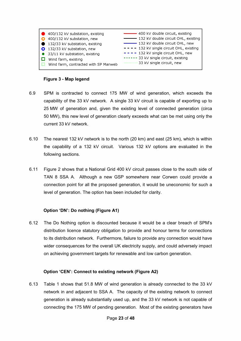
Figure 3 - Map legend
6.9 SPM is contracted to connect 175 MW of wind generation, which exceeds the
capability of the 33 kV network. A single 33 kV circuit is capable of exporting up to
25 MW of generation and, given the existing level of connected generation (circa
50 MW), this new level of generation clearly exceeds what can be met using only the
current 33 kV network.
6.10 The nearest 132 kV network is to the north (20 km) and east (25 km), which is within
the capability of a 132 kV circuit. Various 132 kV options are evaluated in the
following sections.
6.11 Figure 2 shows that a National Grid 400 kV circuit passes close to the south side of
TAN 8 SSA A. Although a new GSP somewhere near Corwen could provide a
connection point for all the proposed generation, it would be uneconomic for such a
level of generation. The option has been included for clarity.
Option ‘DN’: Do nothing (Figure A1)
6.12 The Do Nothing option is discounted because it would be a clear breach of SPM’s
distribution licence statutory obligation to provide and honour terms for connections
to its distribution network. Furthermore, failure to provide any connection would have
wider consequences for the overall UK electricity supply, and could adversely impact
on achieving government targets for renewable and low carbon generation.
Option ‘CEN’: Connect to existing network (Figure A2)
6.13 Table 1 shows that 51.8 MW of wind generation is already connected to the 33 kV
network in and adjacent to SSA A. The capacity of the existing network to connect
generation is already substantially used up, and the 33 kV network is not capable of
connecting the 175 MW of pending generation. Most of the existing generators have

Page 24 of 48
‘unfirm’ connections, which means they are constrained to reduce or cease
generation in the event of a single network contingency, such as maintenance or loss
of a circuit.
6.14 Given the significant existing generation connected to the local 33kV network, the
connection of 3 to 4 times this level of generation would cause significant thermal
issues and risk local security of supply.
6.15 This option is therefore discounted because it would be a breach of SPM’s
distribution licence statutory obligations. The option would not be compliant with the
Electricity Act 1989 as connection to the existing network of such levels of contracted
generation would breach thermal, quality and security of supply.
Option ‘GC’: New Grid Supply Point near Corwen (Figure A3)
6.16 The National Grid Deeside/Legacy to Trawsfynydd 400 kV circuit passes close to the
south of SSA A, and if a new Grid Supply point were established on this circuit
somewhere near Corwen, it could accommodate the generation in SSA A. As well as
the new GSP, which would be provided by National Grid, SPM would also have to
establish a BSP for such a connection.
6.17 Although this is a viable option, the construction of both a GSP and a BSP is a major
development. The cost for both a GSP and BSP must be taken into account as the
associated equipment and construction costs for both would be much greater than an
132 kV overhead line. This option has not been taken forward because of its very
high cost in relation to the amount of generation requiring connection; since Section
9(2) of the Electricity Act 1989 requires SPM to develop and maintain an economical
system of electricity transmission.
Option ‘BL’: 132 kV connection to Brymbo or Legacy
6.18 The 132 kV substations at Brymbo and Legacy are both to the east of SSA A, and
are the same distance from it. A single heavy duty wood pole 132 kV circuit has a
summer rating of 176 MVA, and is therefore just capable, at unity power factor
(UPF), of exporting the contracted generation from SSA A.

Page 25 of 48
6.19 In addition to the network infrastructure required to connect to the wind farms in SSA
A, approximately 35 km of 132 kV HDWP line would need to be constructed.
However, the route of this line would cross the Clwydian Range Area of Outstanding
Natural Beauty (AONB) which is considered a strategic environmental constraint to
an overhead line route.
6.20 If the connection is to Brymbo, it would also be necessary to uprate an existing 132
kV circuit between Brymbo and Legacy.
Option ‘CQ’: 132 kV connection to Connah’s Quay
6.21 The 132 kV substation at Connah’s Quay is to the north east of SSA A. A single
heavy duty wood pole 132 kV circuit has a summer rating of 176 MVA, and is
therefore just capable at UPF of exporting the contracted generation from SSA A.
6.22 In addition to the network infrastructure required to connect to the wind farms in SSA
A, approximately 36 km of 132 kV HDWP line would need to be constructed.
However, the route of this line would cross the Clwydian Range AONB which is
considered a strategic environmental constraint to an overhead line route.
Option ‘H’: 132 kV connection to Holywell
6.23 The 132 kV substation at Holywell is to the north east of SSA A. A single heavy duty
wood pole 132 kV circuit has a summer rating of 176 MVA, and is therefore just
capable at UPF of exporting the contracted generation from SSA A.
6.24 In addition to the network infrastructure required to connect to the wind farms in SSA
A, approximately 30 km of 132 kV HDWP line would need to be constructed.
However, the route of this line would cross the Clwydian Range AONB which is
considered a strategic environmental constraint to an overhead line route.
6.25 It would also be necessary to uprate the existing 132 kV circuit between Holywell and
Connah’s Quay.

Page 26 of 48
Option ‘SA’: 132 kV connection to St Asaph
6.26 The 132 kV substation at St Asaph is to the north of SSA A. A single heavy duty
wood pole 132 kV circuit has a summer rating of 176 MVA, and is therefore just
capable at UPF of exporting the contracted generation from SSA A.
6.27 In addition to the network infrastructure required to connect to the wind farms in SSA
A, approximately 25 km of 132 kV HDWP line would need to be constructed.
6.28 National Grid is currently establishing a GSP at Bodelwyddan which is adjacent to
SPM’s BSP at St Asaph. Therefore any subsequent reinforcement of the 132 kV
network to accommodate the SSA A wind farms is likely to be minimal when
compared to the other options presented here.
Option ‘D’: 132 kV connection to Dolgarrog
6.29 The 132 kV substation at Dolgarrog is to the north west of SSA A. A single heavy
duty wood pole 132 kV circuit has a summer rating of 176 MVA, and is therefore just
capable at UPF of exporting the contracted generation from SSA A.
6.30 In addition to the network infrastructure required to connect to the wind farms in SSA
A, approximately 35 km of 132 kV HDWP line would need to be constructed. It would
also be necessary to reinforce the existing 132 kV system at Dolgarrog by
establishing a 132 kV substation and uprating the 132 kV circuit between Dolgarrog
and St Asaph.
Option ‘T’: 132 kV connection to Trawsfynydd
6.31 The 132 kV substation at Trawsfynydd is to the west south west of SSA A. A single
heavy duty wood pole 132 kV circuit has a summer rating of 176 MVA, and is
therefore just capable at UPF of exporting the contracted generation from SSA A.
6.32 In addition to the network infrastructure required to connect to the wind farms in
SSA A, approximately 45 km of 132 kV HDWP line would need to be constructed.
Trawsfynydd is situated within the Snowdonia National Park which is considered a
strategic environmental constraint to an overhead line route.

Page 27 of 48
7. CONCLUSIONS
7.1 The Report has reviewed options for connecting the 175 MW of wind generation that
is planned for development in TAN 8 SSA A in north Wales, and which is contracted
to connect to the SP Manweb electricity network.
7.2 A summary of the options evaluation is provided in Appendix A, with a more detailed
description in Section 6 of this Report.
7.3 The options presented take into account early routing option investigations and high
level landscape and visual constraints. Detailed route corridor studies will be
undertaken following confirmation of the chosen strategic option.
7.4 The preferred option is for a 132 kV circuit to be constructed from SSA A northwards
to the St Asaph BSP substation (Option SA). This option is technically capable of
accommodating all the contracted generation and has the shortest 132 kV
connection of all the technically viable options that do not require any development at
400 kV. All other things being equal, shorter options are preferred on the basis of
minimising both impacts and costs.
7.5 The option also has the benefit that the 132 kV circuit route does not affect either the
Snowdonia National Park or the Clwydian Range AONB. When comparing the other
option which also avoid the Snowdonia National Park and Clwydian Range AONB,
on the basis of the high level early routing option investigations, it is not considered
that environmental performance is sufficiently different to justify taking forward an
option other than the shortest, lowest cost option. Option ‘D’, which avoids
Snowdonia National Park and the Clwydian Range AONB, does not provide any
additional benefit at an amenity level when compared to the preferred option.
7.6 Options ‘GC’, ‘BL’, ‘CQ’, ‘H’, and ‘T’ are all deemed technically viable options but
have not be taken forward for further study at this time due to additional costs and/or
environmental concerns such as new infrastructure within nationally designated sites.
The options will be reviewed and back-checked as the project progresses as part of
SPM’s iterative design process to confirm the evaluation is still correct.
7.7 Option SA will therefore be taken forward for more detailed assessment and
consultation at the next stage of SPM's iterative design process.

Page 28 of 48
8. ABBREVIATIONS
AAAC All Aluminium Alloy Conductor ACSR Aluminium Conductor Steel Reinforced AONB Area of Outstanding Natural Beauty BSP Bulk Supply Point CUSC Connection and Use of System Code DGIM Distributed Generation Incentive Mechanism DLR Dynamic Line Rating DNO Distribution Network Operator ENA Energy Networks Association GSP Grid Supply Point GW Gigawatt (one thousand megawatts or 109 watts) HDWP Heavy Duty Wood Pole kA Kiloamp (one thousand amps) km Kilometre kV Kilovolt (one thousand volts) MVA Mega Volt Amp (one million volt amps) MVAr Mega Volt Amp reactive (one million volt amps reactive) MW Megawatt (one million watts or 106 watts) MWh Megawatt-hour NG National Grid NGET National Grid Electricity Transmission plc SPEN ScottishPower Energy Networks SPM ScottishPower Manweb plc SGT SuperGrid Transformer sq mm Square millimetre TAN Technical Advice Note TW Terawatt (one million megawatts or 1012 watts) TWh Terawatt-hour UPF Unity Power Factor WG Welsh Government (formally the Welsh Assembly Government, WAG) Wh A unit of energy measurement (1 Wh=3600 joules) XLPE Cross-linked Polyethylene


Page 30 of 48
Appendix A – Options Evaluation Option Description Additional Comments Option Status Summary DN Do Nothing Does not connect any of the
contracted wind farms. Option discounted because breach of SPM’s licence obligation to offer terms for connection.
CEN Connect to Existing Network
Existing network is already close to its limit with existing/contracted generation connections, and there is insufficient spare 33kV capacity to connect the contracted generation.
Option discounted because breach of SPM’s licence obligation to preserve the integrity of the distribution system and offer terms for connection.
GC New GSP near Corwen
Construction of a new GSP on the 400 kV circuit near Corwen, and a new BSP adjacent to it
Although technically satisfactory, this option is discounted because of its higher cost and the time needed to establish 400 kV infrastructure.
BL 132 kV connection to Brymbo or Legacy
35 km of 132 kV HDWP line required from SSA A to Legacy or Brymbo. The 132 kV line crosses the Clwydian Range AONB. For connection at Brymbo, the Brymbo to Legacy 132 kV circuit requires uprating.
Technically satisfactory, but not the lowest cost option.
CQ 132 kV connection to Connah’s Quay
36 km of 132 kV HDWP line required from SSA A to Connah’s Quay. The 132 kV line would cross the Clwydian Range AONB.
Technically satisfactory, but not the lowest cost option.
H 132kV connection to Holywell
30 km of 132 kV HDWP line required from SSA A to Holywell. The 132 kV line would cross the Clwydian Range AONB. The Holywell to Connah’s Quay 132 kV circuit requires uprating
Technically satisfactory, but not the lowest cost option.
SA 132kV connection to St Asaph
25 km of 132 kV HDWP line required from SSA A to St Asaph.
The lowest cost option that is also technically satisfactory.
D 132kV connection to Dolgarrog
35 km of 132 kV HDWP line required from SSA A to Dolgarrog. 132 kV substation required at Dolgarrog. The Dolgarrog to St Asaph 132 kV circuit requires uprating.
Technically satisfactory, but not the lowest cost option.
T 132kV connection to Trawsfynydd
45 km of 132 kV HDWP line required from SSA A to Trawsfynydd. The 132 kV line would go through the Snowdonia National Park.
Technically satisfactory, but not the lowest cost option.

Page 31 of 48
Table A1 Scheme: North Wales Option Reference Option ‘DN’ Option Title Do Nothing
Scope of Works None.
Evaluation Criteria Issues
Economy
n/a
Discount System Compliance
• This is a breach of SPM licence obligation to offer and honour
terms for connection to the SPM distribution network.
Discount Deliverability
n/a
Discount Environmental
• Prevents renewable generation from being connected to the network, thereby limiting potential contributions of renewable energy to reducing carbon dioxide emissions and failing to address environmental effects associated with climate change. Discount
Recommendation: Option to be discounted because it is a clear breach of SPM’s licence
obligation to offer terms for connection.

Page 32 of 48
Figure A1 DN: Do nothing, the existing network and wind farm sites
See Table 1 (Page 11) for wind farm site numbering key See Figure 3 (Page 23) for the map legend

Page 33 of 48
Table A2 Scheme: North Wales Option Reference Option ‘CEN’ Option Title Connect to existing network
Scope of Works • No network reinforcement. • Construct wind farm network infrastructure
Evaluation Criteria Issues
Economical
n/a
Discount System Compliance
• Insufficient capability within the existing network to provide the necessary capacity to connect the required levels of contracted generation;
• This is a breach of SPM licence obligation to design the network in accordance with the Distribution Code (preserve the integrity of the Distribution System); Discount
Deliverability
n/a
Discount Environmental
• Prevents renewable generation from being connected to the
network, thereby limiting potential contributions of renewable energy to reducing carbon dioxide emissions and failing to address environmental effects associated with climate change. Discount
Recommendation: Not a viable option.
Option discounted because it is a breach of SPM’s licence obligation to preserve the integrity of the distribution system and to offer terms for connection.

Page 34 of 48
Figure A2 CEN: Connect to existing network
See Table 1 (Page 11) for wind farm site numbering key See Figure 3 (Page 23) for the map legend

Page 35 of 48
Table A3 Scheme: North Wales Option Reference Option ‘GC’ Option Title New GSP near Corwen
Scope of Works • National Grid to construct new GSP near Corwen • SPM to construct new BSP near Corwen • Construct wind farm network infrastructure
Evaluation Criteria Issues
Economical • Very high cost in relation to the amount of generation being
connected
Discount System Compliance
•
Discount Deliverability
• Development of 400 kV infrastructure will delay the connection of
the wind generation significantly
Discount Environmental
• Minimises requirements for 132kV circuit and associated
environmental effects. Potential for environmental effects associated with the development of a large GSP and BSP sites within a rural setting. Discount
Recommendation: A viable option.
Option not to be taken forward because of high cost and long time required for development

Page 36 of 48
Figure A3 GC: New GSP near Corwen
See Table 1 (Page 11) for wind farm site numbering key See Figure 3 (Page 23) for the map legend

Page 37 of 48
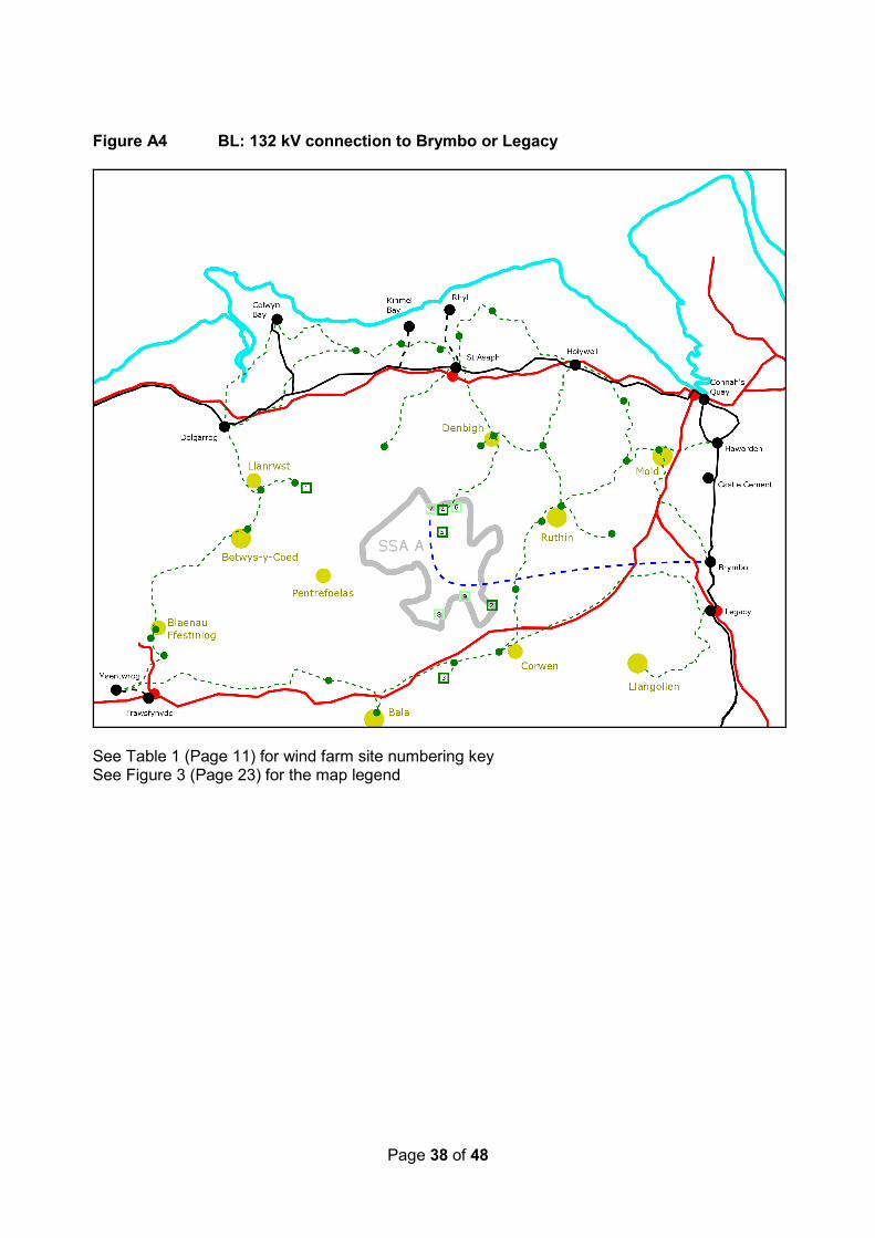
Table A4 Scheme: North Wales Option Reference Option ‘BL’ Option Title 132 kV connection to Brymbo or Legacy
Scope of Works • Construct 35 km of 132 kV HDWP line from SSA A to Brymbo or Legacy, and the connection into Bymbo or Legacy substations
• Uprate the Brymbo to Legacy 132 kV circuit if the connection is into Brymbo
• Construct wind farm network infrastructure Evaluation Criteria Issues
Economical
• Approximately 10 km more 132 kV circuit required than Option SA • If connection is to Brymbo, the Brymbo to Legacy 132 kV circuit
requires uprating Discount
System Compliance
•
Discount Deliverability
•
Discount Environmental
• Any new 132kV overhead line would be required to cross the
Clwydian Range AONB. AONBs are nationally designated areas of high sensitivity to new development. Increases 132kV circuit length and associated potential environmental effects. Discount
Recommendation: A viable option.
Option not to be taken forward because of cost and potential environmental issues.
Page 38 of 48
Figure A4 BL: 132 kV connection to Brymbo or Legacy
See Table 1 (Page 11) for wind farm site numbering key See Figure 3 (Page 23) for the map legend

Page 39 of 48
Table A5 Scheme: North Wales Option Reference Option ‘CQ’ Option Title 132 kV connection to Connah’s Quay
Scope of Works • Construct 36 km of 132 kV HDWP line from SSA A to Connah’s Quay, and the connection into Connah’s Quay substation
• Construct wind farm network infrastructure Evaluation Criteria Issues
Economical
• Approximately 11 km more 132 kV circuit required than Option SA
Discount System Compliance
•
Discount Deliverability
•
Discount Environmental
• 132 kV HDWP line crosses the Clwydian Range AONB. AONBs
are nationally designated areas of high sensitivity to new development. Increases 132kV circuit length and associated potential environmental effects.
Discount Recommendation: A viable option.
Option not to be taken forward because of cost and potential environmental issues.

Page 40 of 48
Figure A5 CQ: 132 kV connection to Connah’s Quay
See Table 1 (Page 11) for wind farm site numbering key See Figure 3 (Page 23) for the map legend

Page 41 of 48
Table A6 Scheme: North Wales Option Reference Option ‘H’ Option Title 132 kV connection to Holywell
Scope of Works • Construct 30 km of 132 kV HDWP line from SSA A to Holywell, and the connection into Holywell substation
• Uprate the Holywell to Connah’s Quay 132 kV circuit • Construct wind farm network infrastructure
Evaluation Criteria Issues
Economical
• Approximately 5 km more 132 kV circuit required than Option SA • The Holywell to Connah’s Quay 132 kV circuit requires uprating
Discount System Compliance
•
Discount Deliverability
•
Discount Environmental
• 132 kV HDWP line crosses the Clwydian Range AONB. AONBs
are nationally designated areas of high sensitivity to new development. Increases 132kV circuit length and associated potential environmental effects. Discount
Recommendation: A viable option.
Option not taken forward because of cost and potential environmental issues.

Page 42 of 48
Figure A6 H: 132 kV connection to Holywell
See Table 1 (Page 11) for wind farm site numbering key See Figure 3 (Page 23) for the map legend

Page 43 of 48
Table A7 Scheme: North Wales Option Reference Option ‘SA’ Option Title 132 kV connection to St Asaph
Scope of Works • Construct 25 km of 132 kV HDWP line from SSA A to St Asaph and the connection into St Asaph
• Construct wind farm network infrastructure Evaluation Criteria Issues
Economical
• The shortest 132 kV connection, other than Option GC (which requires substantial substation development at both BSP and GSP level)
Discount System Compliance
•
Discount Deliverability
•
Discount Environmental
• Minimises 132kV circuit length and therefore associated potential
environmental effects. Can make use of existing topography and landform. Minimal existing electrical infrastructure in the area.
Discount Recommendation: The preferred option.
The lowest cost option that is technically satisfactory.
Page 44 of 48
Figure A7 SA: 132 kV connection to St Asaph
See Table 1 (Page 11) for wind farm site numbering key See Figure 3 (Page 23) for the map legend

Page 45 of 48
Table A8 Scheme: North Wales Option Reference Option ‘D’ Option Title 132 kV connection to Dolgarrog
Scope of Works • Construct 35 km of 132 kV HDWP line from SSA A to Dolgarrog and the connection into Dolgarrog
• Establish a 132 kV substation at Dolgarrog • Uprate the Holywell to Connah’s Quay 132 kV circuit • Construct wind farm network infrastructure
Evaluation Criteria Issues
Economical • Approximately 10 km more 132 kV circuit required than Option SA • A 132 kV substation would need to be established at Dolgarrog
Discount System Compliance
•
Discount Deliverability
•
Discount Environmental
• Increases 132kV circuit length and associated potential
environmental effects. Close proximity to Snowdonia National Park. National Parks are nationally designated areas of high sensitivity to new development. Discount
Recommendation: A viable option.
Option not taken forward because of cost and potential environmental issues.

Page 46 of 48
Figure A8 D: 132 kV connection to Dolgarrog
See Table 1 (Page 11) for wind farm site numbering key See Figure 3 (Page 23) for the map legend

Page 47 of 48
Table A9 Scheme: North Wales Option Reference Option ‘T’ Option Title 132 kV connection to Trawsfynydd
Scope of Works • Construct 45 km of 132 kV HDWP line from SSA A to Trawsfynydd and the connection into Trawsfynydd
• Construct wind farm network infrastructure Evaluation Criteria Issues
Economical
• Approximately 20 km more 132 kV circuit required than Option SA
Discount System Compliance
•
Discount Deliverability
•
Discount Environmental
• A 132 kV HDWP line would be required through Snowdonia
National Park. Increases 132kV circuit length and associated potential environmental effects. National Parks are nationally designated areas of high sensitivity to new development. Discount
Recommendation: A viable option.
Option not taken forward because of cost and potential environmental issues.

Page 48 of 48
Figure A9 T: 132 kV connection to Trawsfynydd
See Table 1 (Page 11) for wind farm site numbering key See Figure 3 (Page 23) for the map legend