Nortel S8000/S12000 CEATS Install
57
Pkgid: 0000003 PROPRIETARY INFORMATION: The information contained in this document is the property of Nortel Networks. Except as specifically authorized in writing, the holder of this document shall keep all information contained herein confidential and shall protect same in whole or in part from disclosure and dissemination to third parties. Nortel Networks 2005 All Rights Reserved Preliminary GSM BTS S8000 & S12000 Outdoor, Temperature Alarm Kit (V2) Installation Installation Method – 65-8189 March 18, 2005 Issue Number: 2.01
-
Upload
kcchiefs00 -
Category
Documents
-
view
154 -
download
1
Transcript of Nortel S8000/S12000 CEATS Install
Pkgid: 0000003 PROPRIETARY INFORMATION: The information contained in this document is the property of Nortel Networks. Except as specifically authorized in writing, the holder of this document shall keep all information contained herein confidential and shall protect same in whole or in part from disclosure and dissemination to third parties.
Nortel Networks 2005 All Rights Reserved
Pre
limin
ary
GSM BTS S8000 & S12000 Outdoor, Temperature Alarm Kit (V2) Installation
Installation Method – 65-8189
March 18, 2005
Issue Number: 2.01

March 18, 2005 Method 65-8189
Pre
limin
ary
Table of Contents1.0 General Information . . . . . . . . . . . . . . . . . . . . . . . . . . . . . . . . . . . . . . . . . . . . . . . . . . . . . . . 6
1.1 Description . . . . . . . . . . . . . . . . . . . . . . . . . . . . . . . . . . . . . . . . . . . . . . . . . . . . . . . . . . . . . 61.2 Sequence . . . . . . . . . . . . . . . . . . . . . . . . . . . . . . . . . . . . . . . . . . . . . . . . . . . . . . . . . . . . . . 61.3 Reason for Reissue . . . . . . . . . . . . . . . . . . . . . . . . . . . . . . . . . . . . . . . . . . . . . . . . . . . . . 6
2.0 Material Requirements . . . . . . . . . . . . . . . . . . . . . . . . . . . . . . . . . . . . . . . . . . . . . . . . . . . . . 72.1 Required Documents . . . . . . . . . . . . . . . . . . . . . . . . . . . . . . . . . . . . . . . . . . . . . . . . . . . . . 7
2.1.1 On BTS Site . . . . . . . . . . . . . . . . . . . . . . . . . . . . . . . . . . . . . . . . . . . . . . . . . . . . . . . 72.1.2 On OMC Site . . . . . . . . . . . . . . . . . . . . . . . . . . . . . . . . . . . . . . . . . . . . . . . . . . . . . . 7
2.2 Tools & Test Sets. . . . . . . . . . . . . . . . . . . . . . . . . . . . . . . . . . . . . . . . . . . . . . . . . . . . . . . . 72.3 Software . . . . . . . . . . . . . . . . . . . . . . . . . . . . . . . . . . . . . . . . . . . . . . . . . . . . . . . . . . . . . . 82.4 Supplies . . . . . . . . . . . . . . . . . . . . . . . . . . . . . . . . . . . . . . . . . . . . . . . . . . . . . . . . . . . . . . 8
3.0 Precautions and Preparations . . . . . . . . . . . . . . . . . . . . . . . . . . . . . . . . . . . . . . . . . . . . . . . 93.1 Precautions . . . . . . . . . . . . . . . . . . . . . . . . . . . . . . . . . . . . . . . . . . . . . . . . . . . . . . . . . . . . 93.2 Preparations. . . . . . . . . . . . . . . . . . . . . . . . . . . . . . . . . . . . . . . . . . . . . . . . . . . . . . . . . . . . 93.3 Check List . . . . . . . . . . . . . . . . . . . . . . . . . . . . . . . . . . . . . . . . . . . . . . . . . . . . . . . . . . . . . 9
4.0 Procedure . . . . . . . . . . . . . . . . . . . . . . . . . . . . . . . . . . . . . . . . . . . . . . . . . . . . . . . . . . . . . . . 104.1 Overview . . . . . . . . . . . . . . . . . . . . . . . . . . . . . . . . . . . . . . . . . . . . . . . . . . . . . . . . . . . . . 104.2 Preliminary Checks . . . . . . . . . . . . . . . . . . . . . . . . . . . . . . . . . . . . . . . . . . . . . . . . . . . . 10
Procedure 1 – Preliminary Checks . . . . . . . . . . . . . . . . . . . . . . . . . . . . . . . . . . . . 104.3 Site Shutdown and Cabinet(s) Power-off . . . . . . . . . . . . . . . . . . . . . . . . . . . . . . . . . . . . . 11
Procedure 2 – Site Shutdown and Cabinet(s) Power-off . . . . . . . . . . . . . . . . . . . 124.4 Temperature Alarm Kit Installation. . . . . . . . . . . . . . . . . . . . . . . . . . . . . . . . . . . . . . . . . . 16
4.4.1 Installation in a BTS 12000 Outdoor Equipped with GIPS . . . . . . . . . . . . . . . . . . . 16Procedure 3 – Installation in a BTS 12000 Outdoor Equipped with GIPS . . . . . . 16
4.4.2 Installation in a BTS 12000 Outdoor Equipped with Mitra/Philips. . . . . . . . . . . . . . 22Procedure 4 – Installation in a BTS 12000 Outdoor Equipped with Mitra/Philips. 22
4.4.3 Installation in a BTS S8000 Outdoor Equipped with GIPS . . . . . . . . . . . . . . . . . . . 28Procedure 5 – Installation in a BTS S8000 Outdoor Equipped with GIPS . . . . . . 28
4.4.4 Installation in a BTS S8000 Outdoor Equipped with APS/Helios or Mitra/Philips. . 35Procedure 6 – Installation in a BTS S8000 Outdoor Equipped with APS/Helios or
Mitra/Philips . . . . . . . . . . . . . . . . . . . . . . . . . . . . . . . . . . . . . . . . . . . . . . . . . . . . 354.5 Cabinet(s) Power-up . . . . . . . . . . . . . . . . . . . . . . . . . . . . . . . . . . . . . . . . . . . . . . . . . . . . 40
Procedure 7 – Cabinet(s) Power-up . . . . . . . . . . . . . . . . . . . . . . . . . . . . . . . . . . . 404.6 Cabinet Visual Check and Site Return to Service. . . . . . . . . . . . . . . . . . . . . . . . . . . . . 41
4.6.1 Visual Checks. . . . . . . . . . . . . . . . . . . . . . . . . . . . . . . . . . . . . . . . . . . . . . . . . . . . . 41Procedure 8 – Visual Checks . . . . . . . . . . . . . . . . . . . . . . . . . . . . . . . . . . . . . . . 41
4.6.2 Site Return to Service. . . . . . . . . . . . . . . . . . . . . . . . . . . . . . . . . . . . . . . . . . . . . . . 42Procedure 9 – Site Return to Service . . . . . . . . . . . . . . . . . . . . . . . . . . . . . . . . . . 42
4.7 Final Checks . . . . . . . . . . . . . . . . . . . . . . . . . . . . . . . . . . . . . . . . . . . . . . . . . . . . . . . . . . 43Procedure 10 – Final Checks . . . . . . . . . . . . . . . . . . . . . . . . . . . . . . . . . . . . . . . . 43
5.0 References . . . . . . . . . . . . . . . . . . . . . . . . . . . . . . . . . . . . . . . . . . . . . . . . . . . . . . . . . . . . . . 44
6.0 Appendices . . . . . . . . . . . . . . . . . . . . . . . . . . . . . . . . . . . . . . . . . . . . . . . . . . . . . . . . . . . . . 45Appendix A – Modification of the Alarm Criteria to be performed at OMC-R . . . . . . . . . . . . 45
Procedure 11 – Modification of the Alarm Criteria to be performed at OMC-R . . 45Appendix B – Inverter and Alarm Functionality Checking . . . . . . . . . . . . . . . . . . . . . . . . . . 47
Procedure 12 – Inverter and Alarm Functionality Checking . . . . . . . . . . . . . . . . 47Appendix C – Tables for Torque Values . . . . . . . . . . . . . . . . . . . . . . . . . . . . . . . . . . . . . . . . 50
GSM BTS S8000 & S12000 Outdoor, Temperature Alarm Kit (V2) Installation / 1

Method 65-8189 March 18, 2005 P
relim
inar
y
Appendix D – Glossary . . . . . . . . . . . . . . . . . . . . . . . . . . . . . . . . . . . . . . . . . . . . . . . . . . . . . 52Appendix E – Report Sheet. . . . . . . . . . . . . . . . . . . . . . . . . . . . . . . . . . . . . . . . . . . . . . . . . . 53Last Page . . . . . . . . . . . . . . . . . . . . . . . . . . . . . . . . . . . . . . . . . . . . . . . . . . . . . . . . . . . . . . . 552 / GSM BTS S8000 & S12000 Outdoor, Temperature Alarm Kit (V2) Installation
March 18, 2005 Method 65-8189
Pre
limin
ary
FiguresFigure 1 – Door Holding Mechanism . . . . . . . . . . . . . . . . . . . . . . . . . . . . . . . . . . . . . . . . . . . 11Figure 2 – Short Circuit on CPCMI Board . . . . . . . . . . . . . . . . . . . . . . . . . . . . . . . . . . . . . . . 13Figure 3 – APS Distribution Module, PCU and DCU Views . . . . . . . . . . . . . . . . . . . . . . . . . . 14Figure 4 – AC Main Module Split Single-Phased . . . . . . . . . . . . . . . . . . . . . . . . . . . . . . . . . . 15Figure 5 – ADUs Views . . . . . . . . . . . . . . . . . . . . . . . . . . . . . . . . . . . . . . . . . . . . . . . . . . . . . 15Figure 6 – EXT. P. Cable on RECAL . . . . . . . . . . . . . . . . . . . . . . . . . . . . . . . . . . . . . . . . . . 16Figure 7 – Port 1 from Cable 1 on RECAL . . . . . . . . . . . . . . . . . . . . . . . . . . . . . . . . . . . . . . 17Figure 8 – Cable SA000147 connected to Port 2 of Cable 1 . . . . . . . . . . . . . . . . . . . . . . . . . 17Figure 9 – USERICO view . . . . . . . . . . . . . . . . . . . . . . . . . . . . . . . . . . . . . . . . . . . . . . . . . . . 18Figure 10 – USERICO out of its mounting location . . . . . . . . . . . . . . . . . . . . . . . . . . . . . . . . 18Figure 11 – Routing of Port 3 of Cable 1 . . . . . . . . . . . . . . . . . . . . . . . . . . . . . . . . . . . . . . . . 19Figure 12 – Alarm Connector on Rectifier Shelf. . . . . . . . . . . . . . . . . . . . . . . . . . . . . . . . . . . 19Figure 13 – Port 4 of Cable 2 and Port 3 of Cable 1 connection . . . . . . . . . . . . . . . . . . . . . . 20Figure 14 – Port 5 of Cable 2 and Alarm connector from BTS connection . . . . . . . . . . . . . . 20Figure 15 – Port 8 Cable 2 on Rectifier Shelf. . . . . . . . . . . . . . . . . . . . . . . . . . . . . . . . . . . . . 21Figure 16 – Port 3 of Cable 1 and Port 4 of Cable 2 in USER ICO Space. . . . . . . . . . . . . . . 21Figure 17 – EXT. P. Cable on RECAL . . . . . . . . . . . . . . . . . . . . . . . . . . . . . . . . . . . . . . . . . 22Figure 18 – Rubber Gasket into Opening . . . . . . . . . . . . . . . . . . . . . . . . . . . . . . . . . . . . . . . 22Figure 19 – Port 1 from Cable 1 on RECAL . . . . . . . . . . . . . . . . . . . . . . . . . . . . . . . . . . . . . 23Figure 20 – Cable SA000147 connected to Port 2 of Cable 1 . . . . . . . . . . . . . . . . . . . . . . . . 24Figure 21 – USERICO view . . . . . . . . . . . . . . . . . . . . . . . . . . . . . . . . . . . . . . . . . . . . . . . . . . 24Figure 22 – USERICO out of its mounting location . . . . . . . . . . . . . . . . . . . . . . . . . . . . . . . . 25Figure 23 – Routing of Port 3 of Cable 1 . . . . . . . . . . . . . . . . . . . . . . . . . . . . . . . . . . . . . . . . 25Figure 24 – Alarm Connector on Rectifier Shelf. . . . . . . . . . . . . . . . . . . . . . . . . . . . . . . . . . . 26Figure 25 – Alarm Connector and Port 3 of Cable 1 Assembly Connection . . . . . . . . . . . . . 27Figure 26 – Alarm Connector and Port 3 Cable 1 in USER ICO Space. . . . . . . . . . . . . . . . . 27Figure 27 – EXT. P. Cable on RECAL . . . . . . . . . . . . . . . . . . . . . . . . . . . . . . . . . . . . . . . . . 28Figure 28 – Rubber Gasket into Opening . . . . . . . . . . . . . . . . . . . . . . . . . . . . . . . . . . . . . . . 28Figure 29 – EXT. P. Cable on RECAL . . . . . . . . . . . . . . . . . . . . . . . . . . . . . . . . . . . . . . . . . 29Figure 30 – Cable NTQA3036 connected to Port 2 of Cable 1 . . . . . . . . . . . . . . . . . . . . . . . 29Figure 31 – DRX/Filler Removed . . . . . . . . . . . . . . . . . . . . . . . . . . . . . . . . . . . . . . . . . . . . . . 30Figure 32 – RX Splitter Removed . . . . . . . . . . . . . . . . . . . . . . . . . . . . . . . . . . . . . . . . . . . . . 30Figure 33 – Panel Filler Removed . . . . . . . . . . . . . . . . . . . . . . . . . . . . . . . . . . . . . . . . . . . . . 31Figure 34 – Battery Power Leads Disconnected . . . . . . . . . . . . . . . . . . . . . . . . . . . . . . . . . . 31Figure 35 – Alarm Connector Location . . . . . . . . . . . . . . . . . . . . . . . . . . . . . . . . . . . . . . . . . 32Figure 36 – Opening on Central Bulkhead Wall. . . . . . . . . . . . . . . . . . . . . . . . . . . . . . . . . . . 32Figure 37 – Port 4 of Cable 2 and Port 3 of Cable 1 connection . . . . . . . . . . . . . . . . . . . . . . 33Figure 38 – Port 5 of Cable 2 and Alarm Connector connection . . . . . . . . . . . . . . . . . . . . . . 33Figure 39 – Port 8 of Cable 2 to Rectifier Shelf connection . . . . . . . . . . . . . . . . . . . . . . . . . . 34Figure 40 – View of Port3 and Port 4 above Rectifier Shelf. . . . . . . . . . . . . . . . . . . . . . . . . . 34Figure 41 – EXT. P. Cable on RECAL . . . . . . . . . . . . . . . . . . . . . . . . . . . . . . . . . . . . . . . . . 35Figure 42 – EXT. P. Cable on RECAL . . . . . . . . . . . . . . . . . . . . . . . . . . . . . . . . . . . . . . . . . 36Figure 43 – Cable NTQA3036 connected to Port 2 of Cable 1 . . . . . . . . . . . . . . . . . . . . . . . 36Figure 44 – DRX/Filler Removed . . . . . . . . . . . . . . . . . . . . . . . . . . . . . . . . . . . . . . . . . . . . . . 37Figure 45 – RX Splitter Removed . . . . . . . . . . . . . . . . . . . . . . . . . . . . . . . . . . . . . . . . . . . . . 37Figure 46 – Battery Power Leads Disconnected . . . . . . . . . . . . . . . . . . . . . . . . . . . . . . . . . . 38Figure 47 – Battery Breaker Panel Filler Removed . . . . . . . . . . . . . . . . . . . . . . . . . . . . . . . . 38Figure 48 – Alarm Connector Location . . . . . . . . . . . . . . . . . . . . . . . . . . . . . . . . . . . . . . . . . 39Figure 49 – Route of Alarm Connector Cable in Opening on Central Bulkhead Wall . . . . . . 39Figure 50 – Alarm Connector and Port 3 of Cable 1 connection . . . . . . . . . . . . . . . . . . . . . . 40Figure 51 – EXT. P. Cable on RECAL . . . . . . . . . . . . . . . . . . . . . . . . . . . . . . . . . . . . . . . . . 47
GSM BTS S8000 & S12000 Outdoor, Temperature Alarm Kit (V2) Installation / 3
Method 65-8189 March 18, 2005 P
relim
inar
y
Figure 52 – Port 1 from Cable 1 on RECAL . . . . . . . . . . . . . . . . . . . . . . . . . . . . . . . . . . . . . 48Figure 53 – Cable SA000147/NTQA3036 connected to Port 2 of Cable 1 . . . . . . . . . . . . . . 484 / GSM BTS S8000 & S12000 Outdoor, Temperature Alarm Kit (V2) Installation
GSM BTS S8000 & S12000 Outdoor, Temperature Alarm Kit (V2) Installation / 5
March 18, 2005 Method 65-8189
Pre
limin
ary
TablesTable 1 – Tools & Test Sets . . . . . . . . . . . . . . . . . . . . . . . . . . . . . . . . . . . . . . . . . . . . . . . . . . . 7Table 2 – Steel Screw 289A Torque Values . . . . . . . . . . . . . . . . . . . . . . . . . . . . . . . . . . . . . 50Table 3 – Stainless Steel Screw Torque Values . . . . . . . . . . . . . . . . . . . . . . . . . . . . . . . . . . 50Table 4 – Terminal Strips Torque Values (Data from CS154.07) . . . . . . . . . . . . . . . . . . . . . 51Table 5 – Miscellaneous Torque Values . . . . . . . . . . . . . . . . . . . . . . . . . . . . . . . . . . . . . . . . 51Table 6 – RF Connections Torque Values . . . . . . . . . . . . . . . . . . . . . . . . . . . . . . . . . . . . . . . 51

Method 65-8189 March 18, 2005 P
relim
inar
y
1.0 General Information1.1 Description
Purpose: This document describes the installation operations of the temperature alarm kit version 2 on a GSM BTS S8000 or S12000 Outdoor site.
Equipment: This document applies to the BTS S8000 and S12000 Outdoor, which characteristics follow:
• BTS with compact BCF (CBCF) inside the base radio cabinet,
• AC/DC power system:
- APS/Helios with AC Main module split phases
- Mitra/Philips with AC Main module split phases
- GIPS Module (usable with single phase, split phases and three phases).
Application: This method is used on a in-service site.
Service Impact: No call processing following a complete site shutdown, to allow the installation of the kit.
Duration of total site unavailability is dependent upon number of cabinets and personnel efficiency.
These operations will be performed at the customers discretion, to limit call attempt failures by the network subscribers.
In case of dropped (chained or looped) BTS, two site shutdowns of a few minutes will occur.
1.2 Sequence
Installation Methods can be found at: http://gis.us.nortel.com
This is a stand-alone method.
1.3 Reason for Reissue
Reason for update:
This is the initial release of this method.
6 / GSM BTS S8000 & S12000 Outdoor, Temperature Alarm Kit (V2) Installation

March 18, 2005 Method 65-8189
Pre
limin
ary
2.0 Material Requirements
2.1 Required Documents
2.1.1 On BTS Site
Regional Installation Safety Manuals (ISM) can be found at:
http://navigate.us.nortel.com/imds?pg=/ops/qual/qmsinstall
For example:
• Americas - Field Operations Safety Manual (SOP 030)
IM 45-9857 GSM BTS S8000 Outdoor Product Safety Installation Requirements,
IM 45-9414 GSM BTS S12000 Outdoor Product Safety Installation Requirements,
IM 28-9401 GSM BTS S8000 & S12000 Faults Isolation.
2.1.2 On OMC Site
IM 30-9615 GSM V13 / V14 / V15 OMC-R Operations Called by BSS I&C Procedures (English MMI)
NTP (411-9001-128) - OMC-R User Manual
2.2 Tools & Test Sets
The Tools and Test Sets listed in Table 1 are required to perform this method.
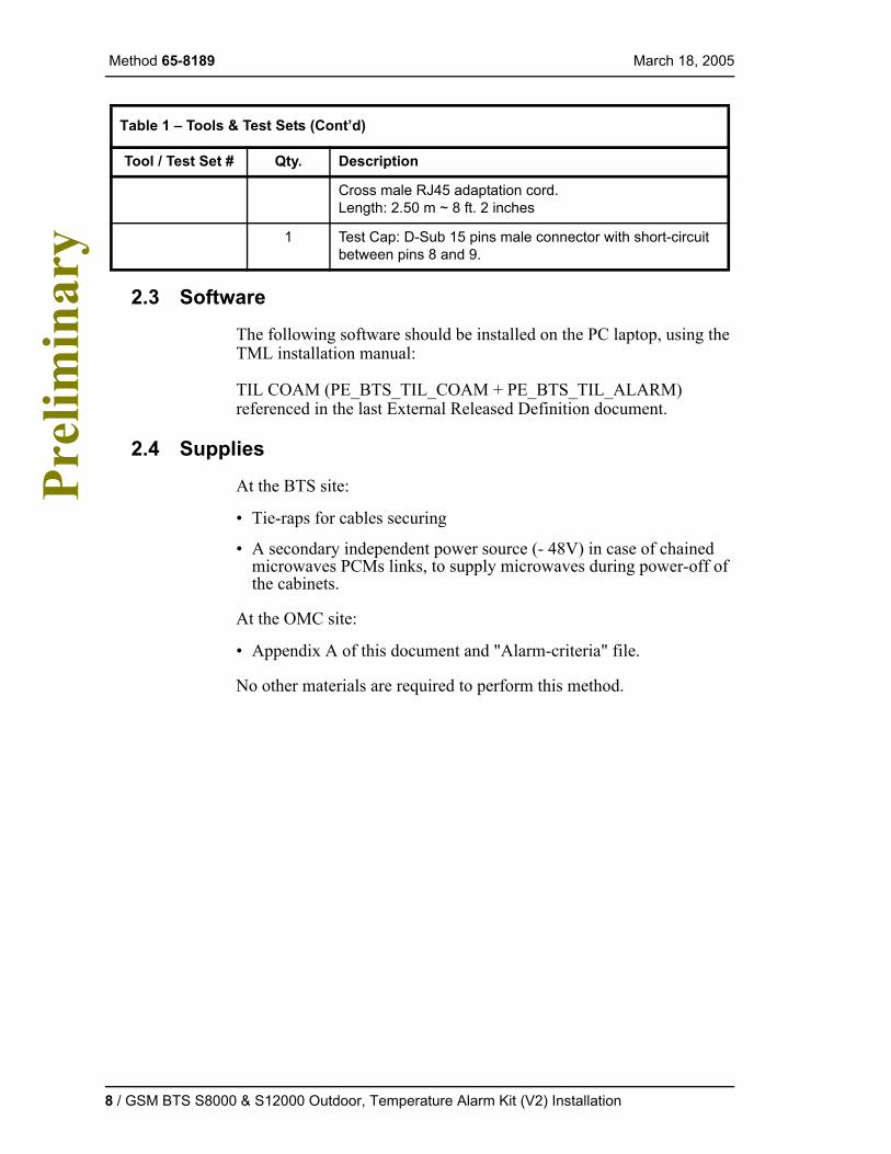
Table 1 – Tools & Test Sets
Tool / Test Set # Qty. Description
K001823 1 Wireless Installer’s Toolkit
T002578 1 Torque wrench SMA (0.8 - 1.2 Nm / 7.08 - 10.6 lbf.in)
1 set Keys to open the S8000 or S12000 Outdoor
T020143 1 Anti-static wrist strap (A0625359)
1 Tent if the weather is rainy or snowy
1 Battery operated lamp, depending on time of intervention
1 Lap-top PC equipped with 1 ethernet portMinimum configuration: PC with 16 Mo RAM under Win-dows 95 with TCP/IP protocol installed
GSM BTS S8000 & S12000 Outdoor, Temperature Alarm Kit (V2) Installation / 7
Method 65-8189 March 18, 2005 P
relim
inar
y
2.3 Software
The following software should be installed on the PC laptop, using the TML installation manual:
TIL COAM (PE_BTS_TIL_COAM + PE_BTS_TIL_ALARM) referenced in the last External Released Definition document.
2.4 Supplies
At the BTS site:
• Tie-raps for cables securing
• A secondary independent power source (- 48V) in case of chained microwaves PCMs links, to supply microwaves during power-off of the cabinets.
At the OMC site:
• Appendix A of this document and "Alarm-criteria" file.
No other materials are required to perform this method.
Cross male RJ45 adaptation cord.Length: 2.50 m ~ 8 ft. 2 inches
1 Test Cap: D-Sub 15 pins male connector with short-circuit between pins 8 and 9.
Table 1 – Tools & Test Sets (Cont’d)
Tool / Test Set # Qty. Description
8 / GSM BTS S8000 & S12000 Outdoor, Temperature Alarm Kit (V2) Installation
March 18, 2005 Method 65-8189
Pre
limin
ary
3.0 Precautions and Preparations
3.1 Precautions
Observe the general safety precautions against personal injury and equipment damage outlined in the regional Installation Safety Manual at all times.
Connections will be made on the Rectifier shelf Controller board. With this in mind, all POWER must be removed from the BTS (both AC and DC via Battery Disconnect).
Cell phone communications may not be possible once power is removed. Ensure there is an alternate means of communication with the OMC-R technician.
3.2 Preparations
It is strongly recommended that this method be read in its entirety before starting the operations presented herein.
Prior to starting the operations presented in this method, arrange all materials, tools, and test equipment at the work location to minimize site outage duration and maximize efficiency.
If sign-offs on procedures in Section 4.0 are customer required, the field technician/customer must place a mark after the completion of each step in the Cust and/or NT block indicating that the step has been completed.
3.3 Check List
Verify the following items have been received and/or accomplished before proceeding with the procedure.
This procedure has been reviewed before kit installation,
The Alarm Temperature Kit (V2) is delivered (NTQA68JB),
Modification of the Alarm Criteria is performed at OMC-R, if not, ask to OMC-R technician to follow the procedure "modification of alarm criteria" in Appendix A – on page 45.
GSM BTS S8000 & S12000 Outdoor, Temperature Alarm Kit (V2) Installation / 9
Method 65-8189 March 18, 2005 P
relim
inar
y
4.0 Procedure4.1 Overview
The information presented in this method covers the following topics:
• Preliminary Checks
• Site Shutdown and Cabinet(s) Power-off
• Installation in a BTS 12000 Outdoor Equipped with GIPS
• Installation in a BTS 12000 Outdoor Equipped with Mitra/Philips
• Installation in a BTS S8000 Outdoor Equipped with GIPS
• Installation in a BTS S8000 Outdoor Equipped with APS/Helios or Mitra/Philips
• Cabinet(s) Power-up
• Visual Checks
• Site Return to Service
• Final Checks
4.2 Preliminary Checks
These procedures describe the initial checks to perform before any operations.
The BTS S8000 Outdoor or S12000 Outdoor is on line.
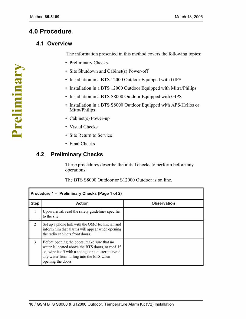
Procedure 1 – Preliminary Checks (Page 1 of 2)
Step Action Observation
1 Upon arrival, read the safety guidelines specific to the site.
2 Set up a phone link with the OMC technician and inform him that alarms will appear when opening the radio cabinets front doors.
3 Before opening the doors, make sure that no water is located above the BTS doors, or roof. If so, wipe it off with a sponge or a duster to avoid any water from falling into the BTS when opening the doors.
10 / GSM BTS S8000 & S12000 Outdoor, Temperature Alarm Kit (V2) Installation
March 18, 2005 Method 65-8189
Pre
limin
ary
4.3 Site Shutdown and Cabinet(s) Power-off
The objective of this procedure step is to power-off the cabinet(s)..
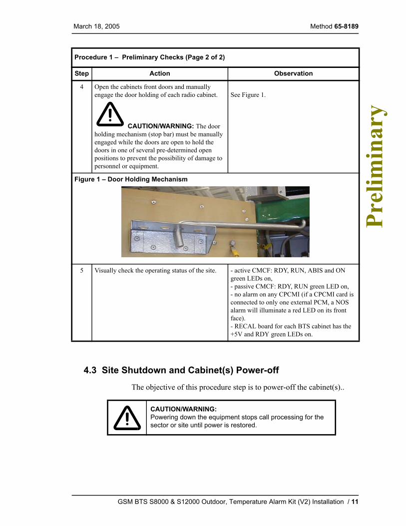
4 Open the cabinets front doors and manually engage the door holding of each radio cabinet.
CAUTION/WARNING: The door holding mechanism (stop bar) must be manually engaged while the doors are open to hold the doors in one of several pre-determined open positions to prevent the possibility of damage to personnel or equipment.
See Figure 1.
Figure 1 – Door Holding Mechanism
5 Visually check the operating status of the site. - active CMCF: RDY, RUN, ABIS and ON green LEDs on,- passive CMCF: RDY, RUN green LED on,- no alarm on any CPCMI (if a CPCMI card is connected to only one external PCM, a NOS alarm will illuminate a red LED on its front face).- RECAL board for each BTS cabinet has the +5V and RDY green LEDs on.
CAUTION/WARNING:Powering down the equipment stops call processing for the sector or site until power is restored.
Procedure 1 – Preliminary Checks (Page 2 of 2)
Step Action Observation
GSM BTS S8000 & S12000 Outdoor, Temperature Alarm Kit (V2) Installation / 11
Method 65-8189 March 18, 2005 P
relim
inar
y
Procedure 2 – Site Shutdown and Cabinet(s) Power-off (Page 1 of 5)Step Action Observation
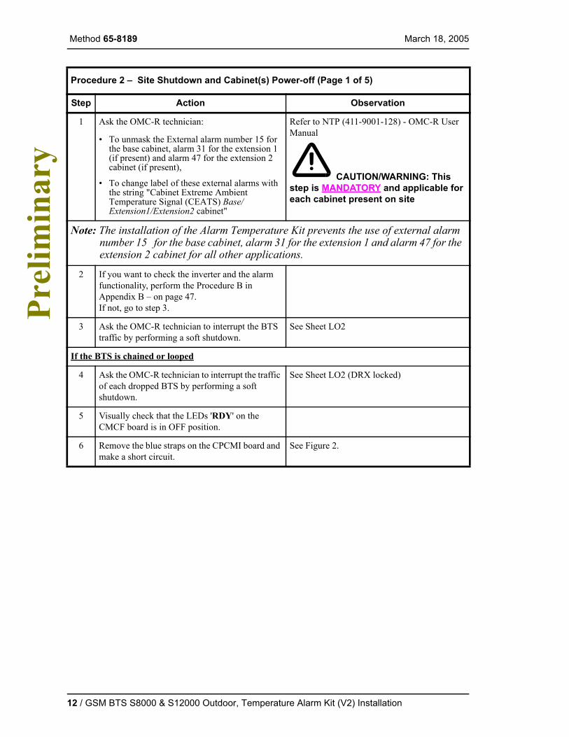
1 Ask the OMC-R technician:
• To unmask the External alarm number 15 for the base cabinet, alarm 31 for the extension 1 (if present) and alarm 47 for the extension 2 cabinet (if present),
• To change label of these external alarms with the string "Cabinet Extreme Ambient Temperature Signal (CEATS) Base/Extension1/Extension2 cabinet"
Refer to NTP (411-9001-128) - OMC-R User Manual
CAUTION/WARNING: This step is MANDATORY and applicable for each cabinet present on site
Note: The installation of the Alarm Temperature Kit prevents the use of external alarm number 15 for the base cabinet, alarm 31 for the extension 1 and alarm 47 for the extension 2 cabinet for all other applications.
2 If you want to check the inverter and the alarm functionality, perform the Procedure B in Appendix B – on page 47.If not, go to step 3.
3 Ask the OMC-R technician to interrupt the BTS traffic by performing a soft shutdown.
See Sheet LO2
If the BTS is chained or looped
4 Ask the OMC-R technician to interrupt the traffic of each dropped BTS by performing a soft shutdown.
See Sheet LO2 (DRX locked)
5 Visually check that the LEDs 'RDY' on the CMCF board is in OFF position.
6 Remove the blue straps on the CPCMI board and make a short circuit.
See Figure 2.
12 / GSM BTS S8000 & S12000 Outdoor, Temperature Alarm Kit (V2) Installation

March 18, 2005 Method 65-8189
Pre
limin
ary
Figure 2 – Short Circuit on CPCMI Board
7 Ask the OMC-R technician to make the shutdown BTS return to service.
See Sheet UN2
In all cases
8 In case of using microwave link, the microwave equipment must be powered by a secondary DC power during the kit installation.
Cabinet(s) power-off
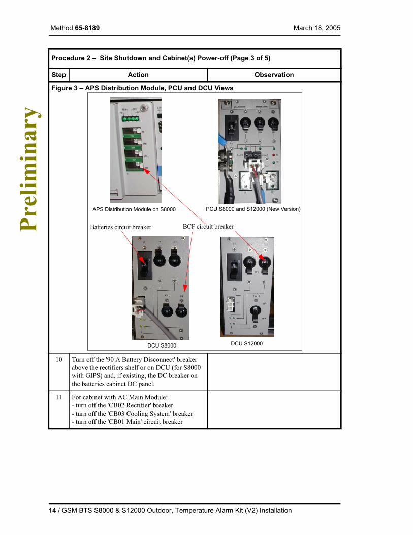
9 Turn off the "BCF" breaker on the APS Distribution module or PCU (Mitra-Philips) or DCU (GIPS).
See Figure 3
Procedure 2 – Site Shutdown and Cabinet(s) Power-off (Page 2 of 5)
Step Action Observation
GSM BTS S8000 & S12000 Outdoor, Temperature Alarm Kit (V2) Installation / 13
Method 65-8189 March 18, 2005 P
relim
inar
y
Figure 3 – APS Distribution Module, PCU and DCU Views
10 Turn off the '90 A Battery Disconnect' breaker above the rectifiers shelf or on DCU (for S8000 with GIPS) and, if existing, the DC breaker on the batteries cabinet DC panel.
11 For cabinet with AC Main Module:- turn off the 'CB02 Rectifier' breaker - turn off the 'CB03 Cooling System' breaker- turn off the 'CB01 Main' circuit breaker
Procedure 2 – Site Shutdown and Cabinet(s) Power-off (Page 3 of 5)
Step Action Observation
Batteries circuit breaker
DCU S8000 DCU S12000
BCF circuit breaker
PCU S8000 and S12000 (New Version)APS Distribution Module on S8000
14 / GSM BTS S8000 & S12000 Outdoor, Temperature Alarm Kit (V2) Installation
March 18, 2005 Method 65-8189
Pre
limin
ary
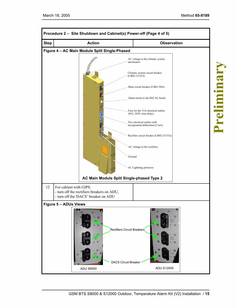
Figure 4 – AC Main Module Split Single-Phased
12 For cabinet with GIPS:- turn off the rectifiers breakers on ADU,- turn off the 'DACS’ breaker on ADU
Figure 5 – ADUs Views
Procedure 2 – Site Shutdown and Cabinet(s) Power-off (Page 4 of 5)
Step Action Observation
AC Main Module Split Single-phased Type 2
AC voltage to the climatic systemand heaters
Climatic system circuit breaker(CB03-15/25A)
Main circuit breaker (CB01-50A)
Rectifier circuit breaker (CB02-25/35A)
Ground
AC Lightning protector
AC voltage to the rectifiers
Alarm return to the RECAL board
Fuse for the 15A electrical outlets(F02, 250V, time delay)
Two electrical outlets withincorporated differential (5 mA)
ADU S8000 ADU S12000
Rectifiers Circuit Breakers
DACS Circuit Breaker
GSM BTS S8000 & S12000 Outdoor, Temperature Alarm Kit (V2) Installation / 15
Method 65-8189 March 18, 2005 P
relim
inar
y
4.4 Temperature Alarm Kit Installation
4.4.1 Installation in a BTS 12000 Outdoor Equipped with GIPS
The objective of this procedure is to install and cable the Temperature Alarm Kit in a BTS 12000 Outdoor equipped with GIPS rectifier shelf.
13 Turn off the site breaker dedicated to each cabinet.
Procedure 3 – Installation in a BTS 12000 Outdoor Equipped with GIPS (Page 1 of 7)
Step Action Observation
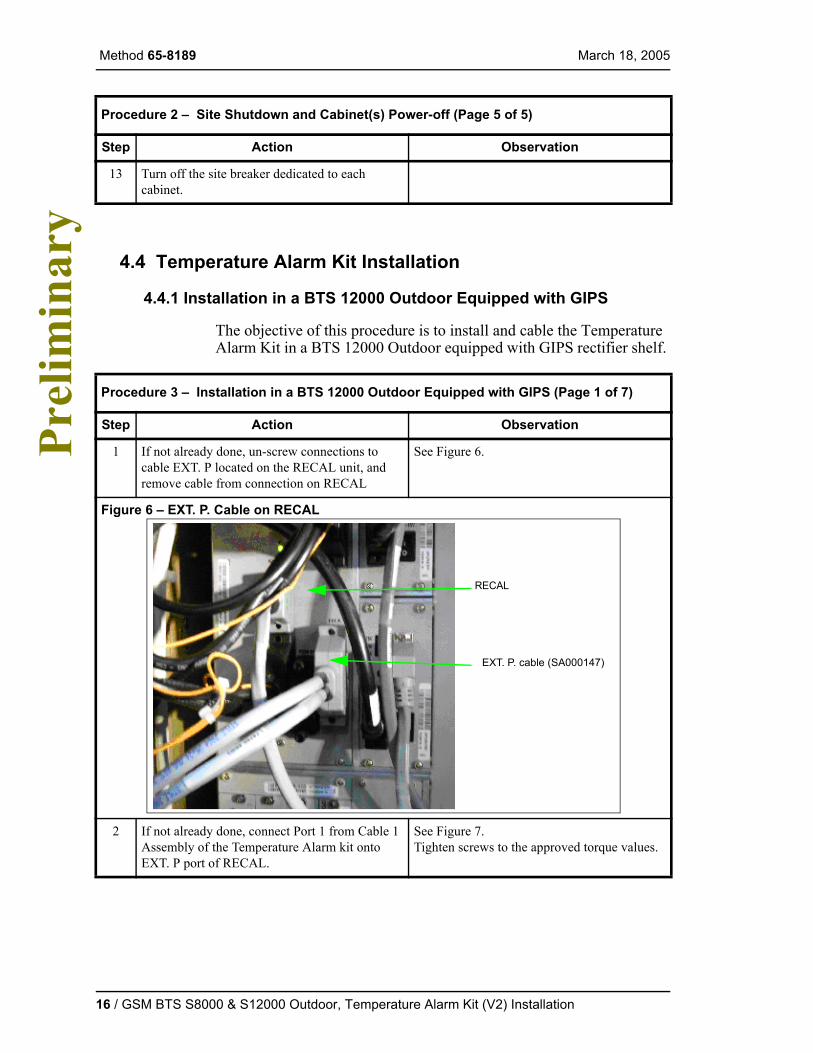
1 If not already done, un-screw connections to cable EXT. P located on the RECAL unit, and remove cable from connection on RECAL
See Figure 6.
Figure 6 – EXT. P. Cable on RECAL
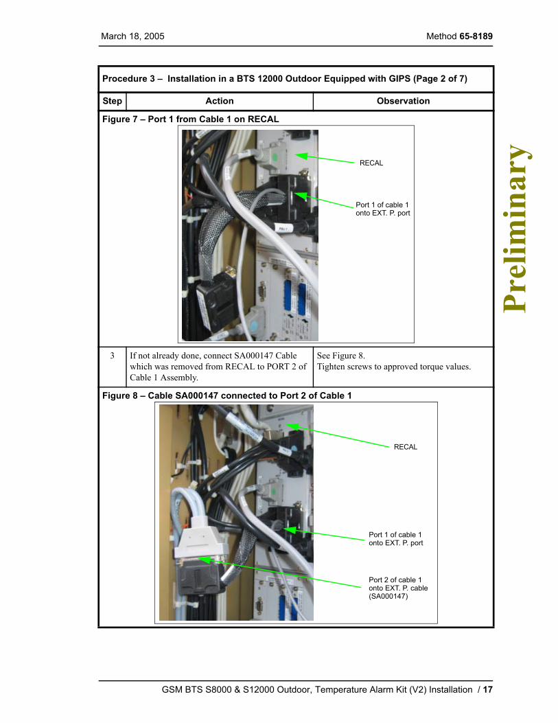
2 If not already done, connect Port 1 from Cable 1 Assembly of the Temperature Alarm kit onto EXT. P port of RECAL.
See Figure 7.Tighten screws to the approved torque values.
Procedure 2 – Site Shutdown and Cabinet(s) Power-off (Page 5 of 5)
Step Action Observation
EXT. P. cable (SA000147)
RECAL
16 / GSM BTS S8000 & S12000 Outdoor, Temperature Alarm Kit (V2) Installation
March 18, 2005 Method 65-8189
Pre
limin
ary
Figure 7 – Port 1 from Cable 1 on RECAL
3 If not already done, connect SA000147 Cable which was removed from RECAL to PORT 2 of Cable 1 Assembly.
See Figure 8.Tighten screws to approved torque values.
Figure 8 – Cable SA000147 connected to Port 2 of Cable 1
Procedure 3 – Installation in a BTS 12000 Outdoor Equipped with GIPS (Page 2 of 7)
Step Action Observation
Port 1 of cable 1
RECAL
onto EXT. P. port
Port 1 of cable 1
RECAL
onto EXT. P. port
Port 2 of cable 1onto EXT. P. cable(SA000147)
GSM BTS S8000 & S12000 Outdoor, Temperature Alarm Kit (V2) Installation / 17
Method 65-8189 March 18, 2005 P
relim
inar
y
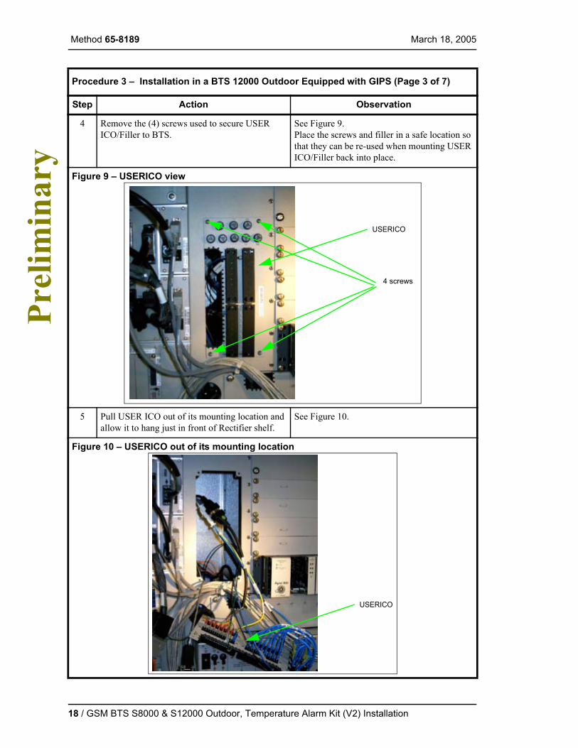
4 Remove the (4) screws used to secure USER ICO/Filler to BTS.
See Figure 9.Place the screws and filler in a safe location so that they can be re-used when mounting USER ICO/Filler back into place.
Figure 9 – USERICO view
5 Pull USER ICO out of its mounting location and allow it to hang just in front of Rectifier shelf.
See Figure 10.
Figure 10 – USERICO out of its mounting location
Procedure 3 – Installation in a BTS 12000 Outdoor Equipped with GIPS (Page 3 of 7)
Step Action Observation
USERICO
4 screws
USERICO
18 / GSM BTS S8000 & S12000 Outdoor, Temperature Alarm Kit (V2) Installation
March 18, 2005 Method 65-8189
Pre
limin
ary
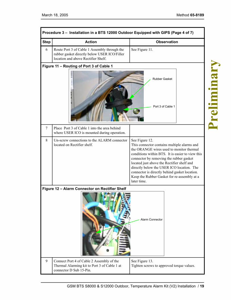
6 Route Port 3 of Cable 1 Assembly through the rubber gasket directly below USER ICO/Filler location and above Rectifier Shelf.
See Figure 11.
Figure 11 – Routing of Port 3 of Cable 1
7 Place Port 3 of Cable 1 into the area behind where USER ICO is mounted during operation.
8 Un-screw connections to the ALARM connector located on Rectifier shelf.
See Figure 12.This connector contains multiple alarms and the ORANGE wires used to monitor thermal conditions within BTS. It is easier to view this connector by removing the rubber gasket located just above the Rectifier shelf and directly below the USER ICO location. The connector is directly behind gasket location. Keep the Rubber Gasket for re-assembly at a later time.
Figure 12 – Alarm Connector on Rectifier Shelf
9 Connect Port 4 of Cable 2 Assembly of the Thermal Alarming kit to Port 3 of Cable 1 at connector D Sub 15-Pin.
See Figure 13.Tighten screws to approved torque values.
Procedure 3 – Installation in a BTS 12000 Outdoor Equipped with GIPS (Page 4 of 7)
Step Action Observation
Rubber Gasket
Port 3 of Cable 1
Alarm Connector
GSM BTS S8000 & S12000 Outdoor, Temperature Alarm Kit (V2) Installation / 19

Method 65-8189 March 18, 2005 P
relim
inar
y
Figure 13 – Port 4 of Cable 2 and Port 3 of Cable 1 connection
10 Connect Alarm Connector from BTS to Port 5 of Cable 2 Assembly.
See Figure 14.Tighten screws to approved torque values.
Figure 14 – Port 5 of Cable 2 and Alarm connector from BTS connection
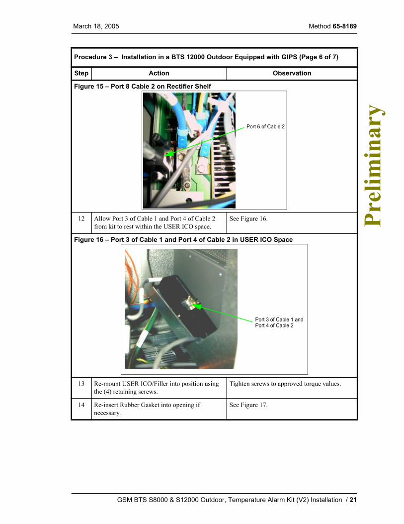
11 Connect Port 6 of Cable 2 to Rectifier Shelf into the location once held by Alarms connector from above.
See Figure 15.Tighten screws to approved torque values.
Procedure 3 – Installation in a BTS 12000 Outdoor Equipped with GIPS (Page 5 of 7)
Step Action Observation
Port 3 of Cable 1
Port 4 of Cable 2
Alarm connector
Port 5 of Cable 2
from BTS
20 / GSM BTS S8000 & S12000 Outdoor, Temperature Alarm Kit (V2) Installation
March 18, 2005 Method 65-8189
Pre
limin
ary
Figure 15 – Port 8 Cable 2 on Rectifier Shelf
12 Allow Port 3 of Cable 1 and Port 4 of Cable 2 from kit to rest within the USER ICO space.
See Figure 16.
Figure 16 – Port 3 of Cable 1 and Port 4 of Cable 2 in USER ICO Space
13 Re-mount USER ICO/Filler into position using the (4) retaining screws.
Tighten screws to approved torque values.
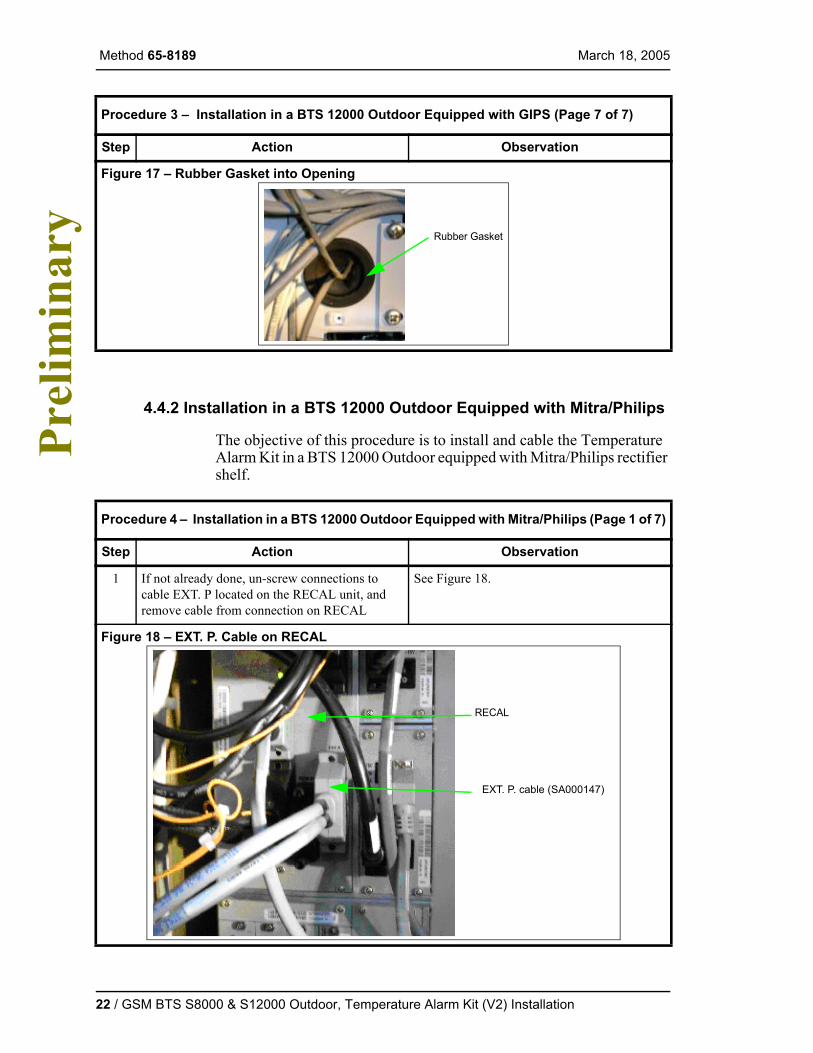
14 Re-insert Rubber Gasket into opening if necessary.
See Figure 17.
Procedure 3 – Installation in a BTS 12000 Outdoor Equipped with GIPS (Page 6 of 7)
Step Action Observation
Port 6 of Cable 2
Port 3 of Cable 1 andPort 4 of Cable 2
GSM BTS S8000 & S12000 Outdoor, Temperature Alarm Kit (V2) Installation / 21
Method 65-8189 March 18, 2005 P
relim
inar
y
4.4.2 Installation in a BTS 12000 Outdoor Equipped with Mitra/Philips
The objective of this procedure is to install and cable the Temperature Alarm Kit in a BTS 12000 Outdoor equipped with Mitra/Philips rectifier shelf.
Figure 17 – Rubber Gasket into Opening
Procedure 4 – Installation in a BTS 12000 Outdoor Equipped with Mitra/Philips (Page 1 of 7)
Step Action Observation
1 If not already done, un-screw connections to cable EXT. P located on the RECAL unit, and remove cable from connection on RECAL
See Figure 18.
Figure 18 – EXT. P. Cable on RECAL
Procedure 3 – Installation in a BTS 12000 Outdoor Equipped with GIPS (Page 7 of 7)
Step Action Observation
Rubber Gasket
EXT. P. cable (SA000147)
RECAL
22 / GSM BTS S8000 & S12000 Outdoor, Temperature Alarm Kit (V2) Installation

March 18, 2005 Method 65-8189
Pre
limin
ary
2 If not already done, connect Port 1 from Cable 1 Assembly of the Temperature Alarm kit onto EXT. P port of RECAL.
See Figure 19.Tighten screws to the approved torque values.
Figure 19 – Port 1 from Cable 1 on RECAL
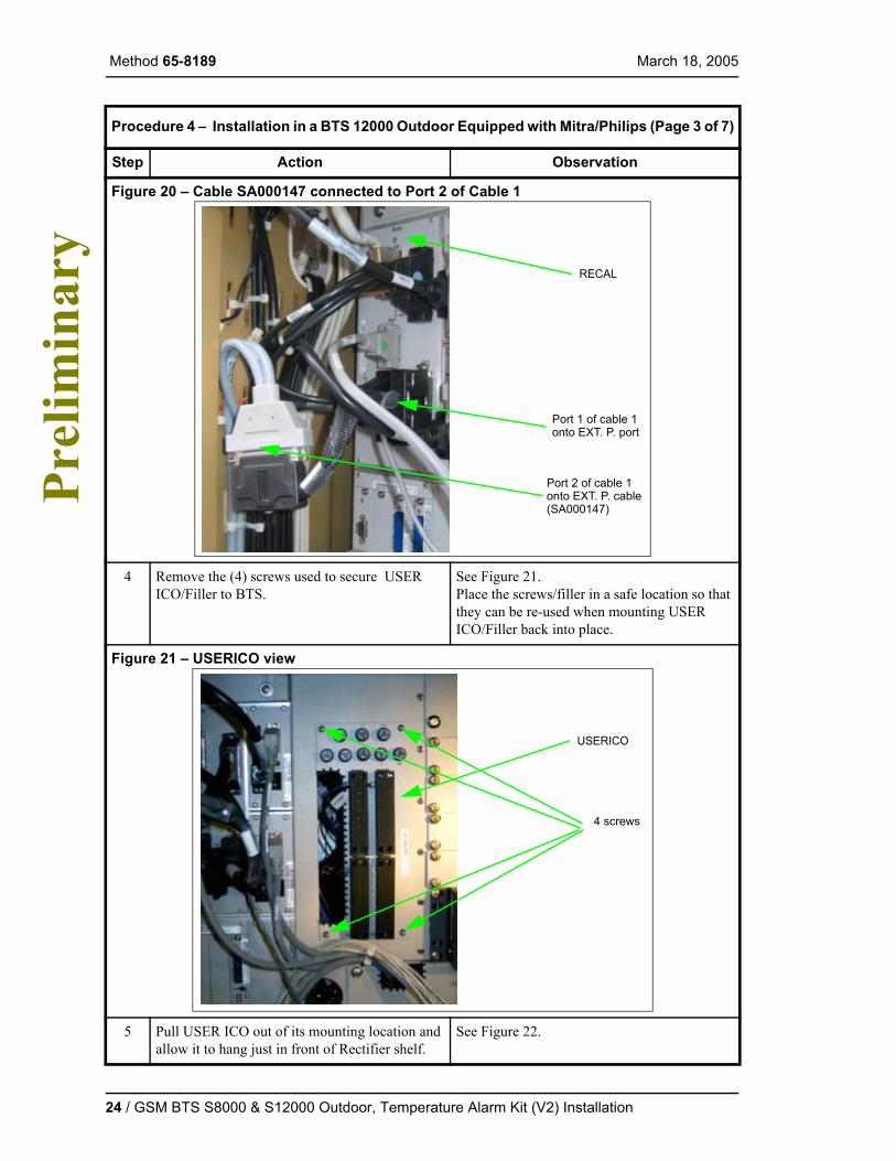
3 If not already done, connect SA000147 Cable which was removed from RECAL to PORT 2 of Cable 1 Assembly.
See Figure 20.Tighten screws to the approved torque values.
Procedure 4 – Installation in a BTS 12000 Outdoor Equipped with Mitra/Philips (Page 2 of 7)
Step Action Observation
Port 1 of cable 1
RECAL
onto EXT. P. port
GSM BTS S8000 & S12000 Outdoor, Temperature Alarm Kit (V2) Installation / 23
Method 65-8189 March 18, 2005 P
relim
inar
y
Figure 20 – Cable SA000147 connected to Port 2 of Cable 1
4 Remove the (4) screws used to secure USER ICO/Filler to BTS.
See Figure 21.Place the screws/filler in a safe location so that they can be re-used when mounting USER ICO/Filler back into place.
Figure 21 – USERICO view
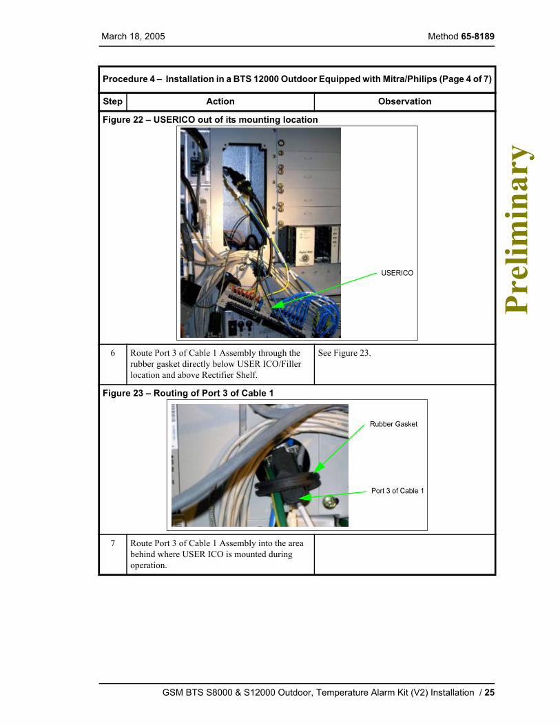
5 Pull USER ICO out of its mounting location and allow it to hang just in front of Rectifier shelf.
See Figure 22.
Procedure 4 – Installation in a BTS 12000 Outdoor Equipped with Mitra/Philips (Page 3 of 7)
Step Action Observation
Port 1 of cable 1
RECAL
onto EXT. P. port
Port 2 of cable 1onto EXT. P. cable(SA000147)
USERICO
4 screws
24 / GSM BTS S8000 & S12000 Outdoor, Temperature Alarm Kit (V2) Installation
March 18, 2005 Method 65-8189
Pre
limin
ary
Figure 22 – USERICO out of its mounting location
6 Route Port 3 of Cable 1 Assembly through the rubber gasket directly below USER ICO/Filler location and above Rectifier Shelf.
See Figure 23.
Figure 23 – Routing of Port 3 of Cable 1
7 Route Port 3 of Cable 1 Assembly into the area behind where USER ICO is mounted during operation.
Procedure 4 – Installation in a BTS 12000 Outdoor Equipped with Mitra/Philips (Page 4 of 7)
Step Action Observation
USERICO
Rubber Gasket
Port 3 of Cable 1
GSM BTS S8000 & S12000 Outdoor, Temperature Alarm Kit (V2) Installation / 25

Method 65-8189 March 18, 2005 P
relim
inar
y
8 Un-screw connections to the ALARM connector located on Rectifier shelf.
See Figure 24.This connector is GREY in color and only has the alarms used to monitor thermal conditions within the BTS. It is easier to view this connector by removing the Rubber Gasket located just above the Rectifier shelf and directly below the USER ICO location. Keep the rubber gasket for re-assembly at a later time. The connector is the second connection back on the PCB directly behind gasket location.
Figure 24 – Alarm Connector on Rectifier Shelf
9 Connect Alarm Connector to Port 3 of Cable 1 Assembly which is a D Sub 15-Pin connection.
See Figure 25.Tighten screws to the approved torque values.
Procedure 4 – Installation in a BTS 12000 Outdoor Equipped with Mitra/Philips (Page 5 of 7)
Step Action Observation
Alarm Connectoron Rectifier Shelf
26 / GSM BTS S8000 & S12000 Outdoor, Temperature Alarm Kit (V2) Installation

March 18, 2005 Method 65-8189
Pre
limin
ary
Figure 25 – Alarm Connector and Port 3 of Cable 1 Assembly Connection
10 Allow Alarm Connector and Port 3 of Cable 1 from kit to rest within the USER ICO space.
See Figure 26.
Figure 26 – Alarm Connector and Port 3 Cable 1 in USER ICO Space
11 Re-mount USER ICO/Filler into position using the (4) retaining screws.
Tighten screws to the approved torque values.
12 Re-insert Rubber Gasket into opening if necessary.
See Figure 27.
Procedure 4 – Installation in a BTS 12000 Outdoor Equipped with Mitra/Philips (Page 6 of 7)
Step Action Observation
Alarm Connector
Port 3 of Cable 1
Ty-rap
and Port 3 of Cable 1Alarm Connector
GSM BTS S8000 & S12000 Outdoor, Temperature Alarm Kit (V2) Installation / 27
Method 65-8189 March 18, 2005 P
relim
inar
y
4.4.3 Installation in a BTS S8000 Outdoor Equipped with GIPS
The objective of this procedure is to install and cable the Temperature Alarm Kit in a BTS S8000 Outdoor equipped with GIPS rectifer shelf.
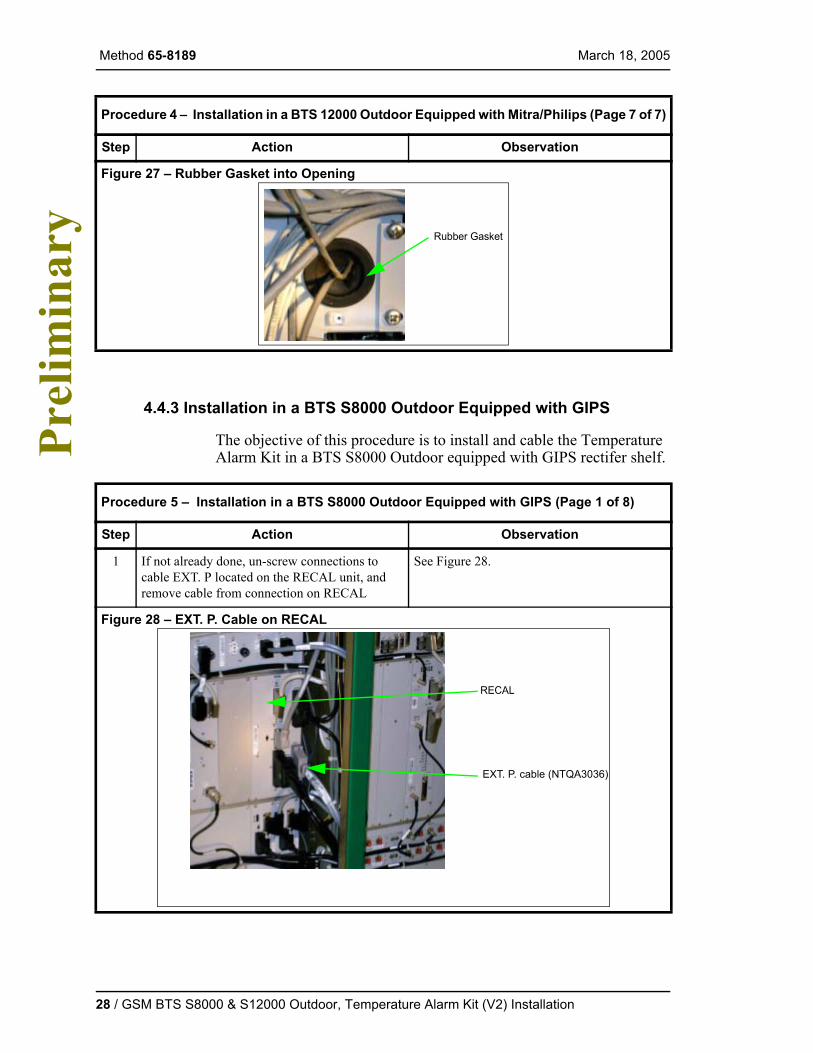
Figure 27 – Rubber Gasket into Opening
Procedure 5 – Installation in a BTS S8000 Outdoor Equipped with GIPS (Page 1 of 8)
Step Action Observation
1 If not already done, un-screw connections to cable EXT. P located on the RECAL unit, and remove cable from connection on RECAL
See Figure 28.
Figure 28 – EXT. P. Cable on RECAL
Procedure 4 – Installation in a BTS 12000 Outdoor Equipped with Mitra/Philips (Page 7 of 7)
Step Action Observation
Rubber Gasket
EXT. P. cable (NTQA3036)
RECAL
28 / GSM BTS S8000 & S12000 Outdoor, Temperature Alarm Kit (V2) Installation
March 18, 2005 Method 65-8189
Pre
limin
ary
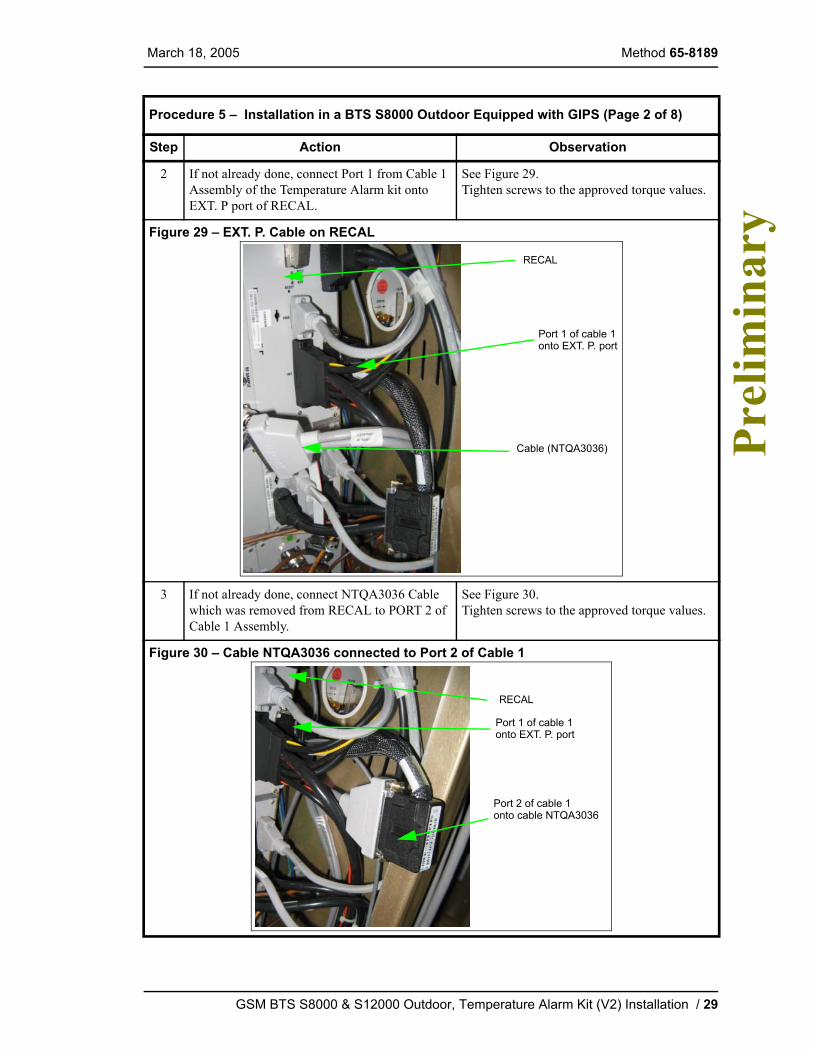
2 If not already done, connect Port 1 from Cable 1 Assembly of the Temperature Alarm kit onto EXT. P port of RECAL.
See Figure 29.Tighten screws to the approved torque values.
Figure 29 – EXT. P. Cable on RECAL
3 If not already done, connect NTQA3036 Cable which was removed from RECAL to PORT 2 of Cable 1 Assembly.
See Figure 30.Tighten screws to the approved torque values.
Figure 30 – Cable NTQA3036 connected to Port 2 of Cable 1
Procedure 5 – Installation in a BTS S8000 Outdoor Equipped with GIPS (Page 2 of 8)
Step Action Observation
Port 1 of cable 1
RECAL
onto EXT. P. port
Cable (NTQA3036)
Port 1 of cable 1
RECAL
onto EXT. P. port
Port 2 of cable 1onto cable NTQA3036
GSM BTS S8000 & S12000 Outdoor, Temperature Alarm Kit (V2) Installation / 29
Method 65-8189 March 18, 2005 P
relim
inar
y
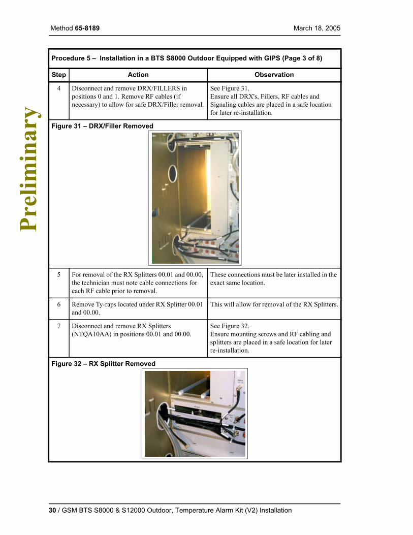
4 Disconnect and remove DRX/FILLERS in positions 0 and 1. Remove RF cables (if necessary) to allow for safe DRX/Filler removal.
See Figure 31.Ensure all DRX's, Fillers, RF cables and Signaling cables are placed in a safe location for later re-installation.
Figure 31 – DRX/Filler Removed
5 For removal of the RX Splitters 00.01 and 00.00, the technician must note cable connections for each RF cable prior to removal.
These connections must be later installed in the exact same location.
6 Remove Ty-raps located under RX Splitter 00.01 and 00.00.
This will allow for removal of the RX Splitters.
7 Disconnect and remove RX Splitters (NTQA10AA) in positions 00.01 and 00.00.
See Figure 32.Ensure mounting screws and RF cabling and splitters are placed in a safe location for later re-installation.
Figure 32 – RX Splitter Removed
Procedure 5 – Installation in a BTS S8000 Outdoor Equipped with GIPS (Page 3 of 8)
Step Action Observation
30 / GSM BTS S8000 & S12000 Outdoor, Temperature Alarm Kit (V2) Installation

March 18, 2005 Method 65-8189
Pre
limin
ary
8 Remove Panel Filler above the rectifier shelf. See Figure 33.So, you can easily view the connections on the Rectifier shelf.Ensure mounting screws and Panel Filler are placed in a safe location for later re-installation.
Figure 33 – Panel Filler Removed
9 Disconnect the both power leads (-48 Vdc and 0 Vdc) at the battery.
See Figure 34.Due to the close proximity of the - 48 Vdc battery cable connections, Battery POWER should be disconnected at the Battery prior to moving to the next step.
Figure 34 – Battery Power Leads Disconnected
10 Un-screw connections to the ALARM connector located on Rectifier shelf.
See Figure 35.This connector contains multiple alarms as well as the GREY wires used to monitor thermal conditions within the BTS.
Procedure 5 – Installation in a BTS S8000 Outdoor Equipped with GIPS (Page 4 of 8)
Step Action Observation
Battery Return- 48 Vdc cable0 Vdc cable
GSM BTS S8000 & S12000 Outdoor, Temperature Alarm Kit (V2) Installation / 31
Method 65-8189 March 18, 2005 P
relim
inar
y
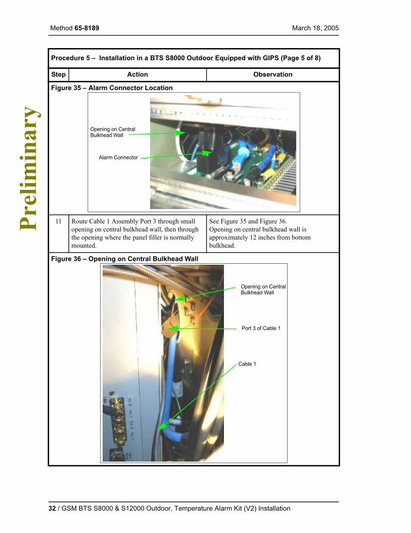
Figure 35 – Alarm Connector Location
11 Route Cable 1 Assembly Port 3 through small opening on central bulkhead wall, then through the opening where the panel filler is normally mounted.
See Figure 35 and Figure 36.Opening on central bulkhead wall is approximately 12 inches from bottom bulkhead.
Figure 36 – Opening on Central Bulkhead Wall
Procedure 5 – Installation in a BTS S8000 Outdoor Equipped with GIPS (Page 5 of 8)
Step Action Observation
Opening on CentralBulkhead Wall
Alarm Connector
Opening on CentralBulkhead Wall
Port 3 of Cable 1
Cable 1
32 / GSM BTS S8000 & S12000 Outdoor, Temperature Alarm Kit (V2) Installation
March 18, 2005 Method 65-8189
Pre
limin
ary
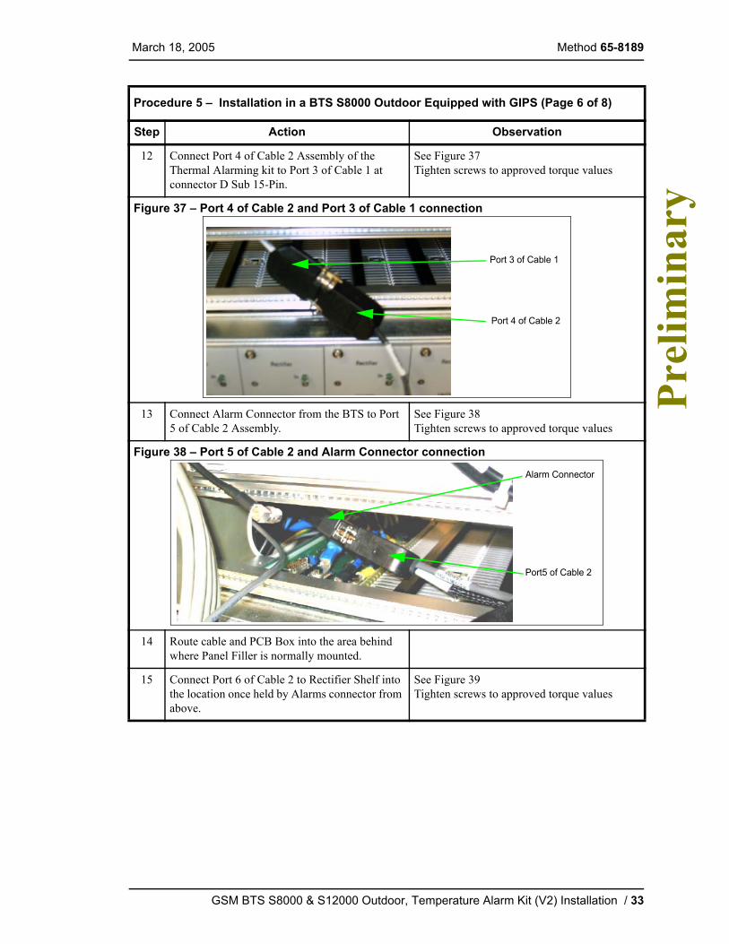
12 Connect Port 4 of Cable 2 Assembly of the Thermal Alarming kit to Port 3 of Cable 1 at connector D Sub 15-Pin.
See Figure 37Tighten screws to approved torque values
Figure 37 – Port 4 of Cable 2 and Port 3 of Cable 1 connection
13 Connect Alarm Connector from the BTS to Port 5 of Cable 2 Assembly.
See Figure 38Tighten screws to approved torque values
Figure 38 – Port 5 of Cable 2 and Alarm Connector connection
14 Route cable and PCB Box into the area behind where Panel Filler is normally mounted.
15 Connect Port 6 of Cable 2 to Rectifier Shelf into the location once held by Alarms connector from above.
See Figure 39Tighten screws to approved torque values
Procedure 5 – Installation in a BTS S8000 Outdoor Equipped with GIPS (Page 6 of 8)
Step Action Observation
Port 3 of Cable 1
Port 4 of Cable 2
Port5 of Cable 2
Alarm Connector
GSM BTS S8000 & S12000 Outdoor, Temperature Alarm Kit (V2) Installation / 33
Method 65-8189 March 18, 2005 P
relim
inar
y
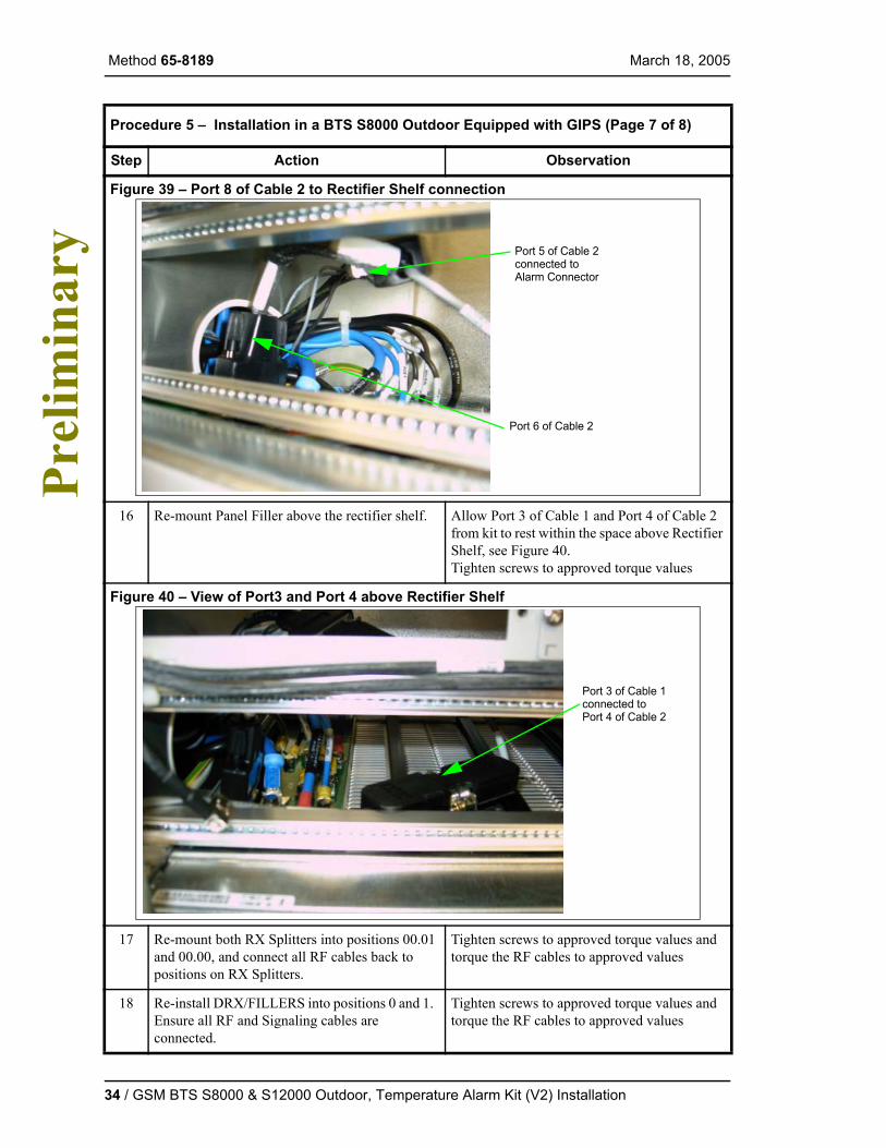
Figure 39 – Port 8 of Cable 2 to Rectifier Shelf connection
16 Re-mount Panel Filler above the rectifier shelf. Allow Port 3 of Cable 1 and Port 4 of Cable 2 from kit to rest within the space above Rectifier Shelf, see Figure 40.Tighten screws to approved torque values
Figure 40 – View of Port3 and Port 4 above Rectifier Shelf
17 Re-mount both RX Splitters into positions 00.01 and 00.00, and connect all RF cables back to positions on RX Splitters.
Tighten screws to approved torque values and torque the RF cables to approved values
18 Re-install DRX/FILLERS into positions 0 and 1. Ensure all RF and Signaling cables are connected.
Tighten screws to approved torque values and torque the RF cables to approved values
Procedure 5 – Installation in a BTS S8000 Outdoor Equipped with GIPS (Page 7 of 8)
Step Action Observation
Port 6 of Cable 2
Port 5 of Cable 2connected toAlarm Connector
Port 3 of Cable 1connected toPort 4 of Cable 2
34 / GSM BTS S8000 & S12000 Outdoor, Temperature Alarm Kit (V2) Installation

March 18, 2005 Method 65-8189
Pre
limin
ary
4.4.4 Installation in a BTS S8000 Outdoor Equipped with APS/Helios or Mitra/Philips
The objective of this procedure is to install and cable the Temperature Alarm Kit in a BTS S8000 Outdoor equipped with APS Helios or Mitra/Philips rectifier shelf.
19 Re-connect battery power leads. Tighten screws to approved torque values
Procedure 6 – Installation in a BTS S8000 Outdoor Equipped with APS/Helios or Mitra/Phil-ips (Page 1 of 6)
Step Action Observation
1 If not already done, un-screw connections to cable EXT. P located on the RECAL unit, and remove cable from connection on RECAL
See Figure 41.
Figure 41 – EXT. P. Cable on RECAL
2 If not already done, connect Port 1 from Cable 1 Assembly of the Temperature Alarm kit onto EXT. P port of RECAL.
See Figure 42.Tighten screws to the approved torque values.
Procedure 5 – Installation in a BTS S8000 Outdoor Equipped with GIPS (Page 8 of 8)
Step Action Observation
EXT. P. cable (NTQA3036)
RECAL
GSM BTS S8000 & S12000 Outdoor, Temperature Alarm Kit (V2) Installation / 35
Method 65-8189 March 18, 2005 P
relim
inar
y
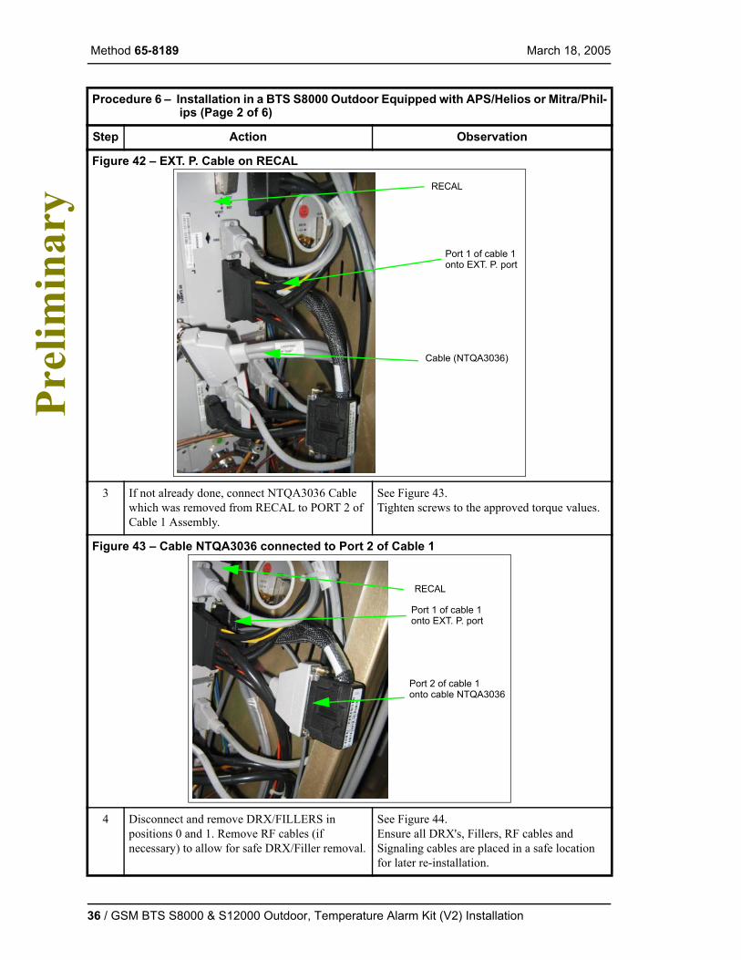
Figure 42 – EXT. P. Cable on RECAL
3 If not already done, connect NTQA3036 Cable which was removed from RECAL to PORT 2 of Cable 1 Assembly.
See Figure 43.Tighten screws to the approved torque values.
Figure 43 – Cable NTQA3036 connected to Port 2 of Cable 1
4 Disconnect and remove DRX/FILLERS in positions 0 and 1. Remove RF cables (if necessary) to allow for safe DRX/Filler removal.
See Figure 44.Ensure all DRX's, Fillers, RF cables and Signaling cables are placed in a safe location for later re-installation.
Procedure 6 – Installation in a BTS S8000 Outdoor Equipped with APS/Helios or Mitra/Phil-ips (Page 2 of 6)
Step Action Observation
Port 1 of cable 1
RECAL
onto EXT. P. port
Cable (NTQA3036)
Port 1 of cable 1
RECAL
onto EXT. P. port
Port 2 of cable 1onto cable NTQA3036
36 / GSM BTS S8000 & S12000 Outdoor, Temperature Alarm Kit (V2) Installation

March 18, 2005 Method 65-8189
Pre
limin
ary
Figure 44 – DRX/Filler Removed
5 For removal of the RX Splitters 00.01 and 00.00, the technician must note cable connections for each RF cable prior to removal.
These connections must be later installed in the exact same location.
6 Remove Ty-raps located under RX Splitter 00.01 and 00.00.
This will allow for removal of the RX Splitters.
7 Disconnect and remove RX Splitters (NTQA10AA) in positions 00.01 and 00.00.
See Figure 45.Ensure mounting screws and RF cabling and splitters are placed in a safe location for later re-installation.
Figure 45 – RX Splitter Removed
8 Disconnect the both power leads (-48 Vdc and 0 Vdc) at the battery.
See Figure 46.Due to the close proximity of the - 48 Vdc Battery Disconnect switch, Battery POWER should be disconnected at the Battery prior to moving to the next step.
Procedure 6 – Installation in a BTS S8000 Outdoor Equipped with APS/Helios or Mitra/Phil-ips (Page 3 of 6)
Step Action Observation
GSM BTS S8000 & S12000 Outdoor, Temperature Alarm Kit (V2) Installation / 37
Method 65-8189 March 18, 2005 P
relim
inar
y
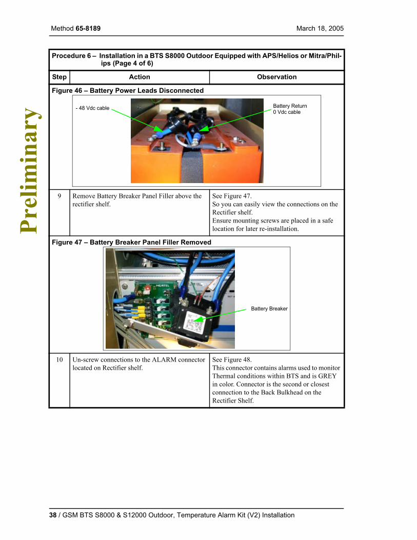
Figure 46 – Battery Power Leads Disconnected
9 Remove Battery Breaker Panel Filler above the rectifier shelf.
See Figure 47.So you can easily view the connections on the Rectifier shelf.Ensure mounting screws are placed in a safe location for later re-installation.
Figure 47 – Battery Breaker Panel Filler Removed
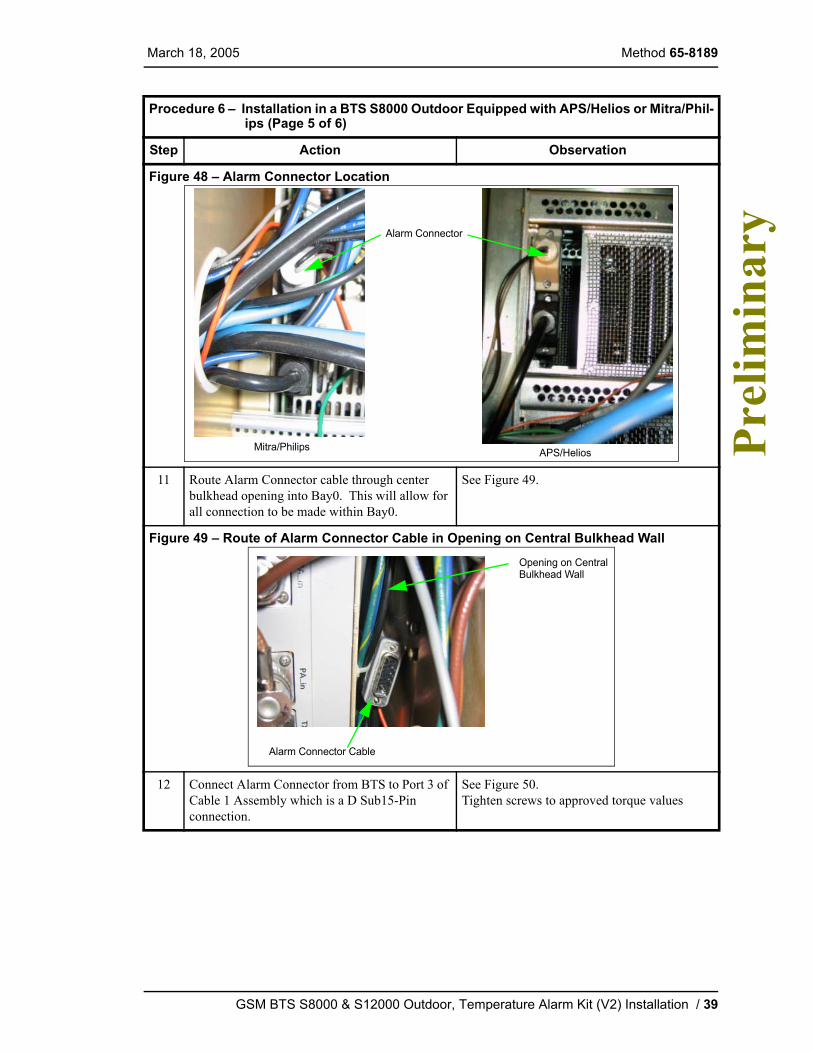
10 Un-screw connections to the ALARM connector located on Rectifier shelf.
See Figure 48.This connector contains alarms used to monitor Thermal conditions within BTS and is GREY in color. Connector is the second or closest connection to the Back Bulkhead on the Rectifier Shelf.
Procedure 6 – Installation in a BTS S8000 Outdoor Equipped with APS/Helios or Mitra/Phil-ips (Page 4 of 6)
Step Action Observation
Battery Return- 48 Vdc cable0 Vdc cable
Battery Breaker
38 / GSM BTS S8000 & S12000 Outdoor, Temperature Alarm Kit (V2) Installation
March 18, 2005 Method 65-8189
Pre
limin
ary
Figure 48 – Alarm Connector Location
11 Route Alarm Connector cable through center bulkhead opening into Bay0. This will allow for all connection to be made within Bay0.
See Figure 49.
Figure 49 – Route of Alarm Connector Cable in Opening on Central Bulkhead Wall
12 Connect Alarm Connector from BTS to Port 3 of Cable 1 Assembly which is a D Sub15-Pin connection.
See Figure 50.Tighten screws to approved torque values
Procedure 6 – Installation in a BTS S8000 Outdoor Equipped with APS/Helios or Mitra/Phil-ips (Page 5 of 6)
Step Action Observation
Alarm Connector
APS/HeliosMitra/Philips
Alarm Connector Cable
Opening on CentralBulkhead Wall
GSM BTS S8000 & S12000 Outdoor, Temperature Alarm Kit (V2) Installation / 39

Method 65-8189 March 18, 2005 P
relim
inar
y
4.5 Cabinet(s) Power-up
Proceed the following for each cabinet.
Important: The main (base) cabinet must be powered last otherwise the extension cabinet(s) will not be taken into account.
Figure 50 – Alarm Connector and Port 3 of Cable 1 connection
13 Re-mount Battery Breaker Panel Filler above the rectifier shelf.
Tighten screws to approved torque values
14 Re-mount both RX Splitters into positions 00.01 and 00.00, and connect all RF cables back to positions on RX Splitters.
Tighten screws to approved torque values and torque the RF cables to approved values
15 Re-install DRX/FILLERS into positions 0 and 1. Ensure all RF and Signaling cables are connected.
Tighten screws to approved torque values and torque the RF cables to approved values
16 Re-connect battery power leads. Tighten screws to approved torque values
Procedure 7 – Cabinet(s) Power-up (Page 1 of 2)
Step Action Observation
1 Turn on the site breaker(s) dedicated to the initial cabinet(s).
2 Turn on the AC 'Main' circuit breaker (CB01).
Procedure 6 – Installation in a BTS S8000 Outdoor Equipped with APS/Helios or Mitra/Phil-ips (Page 6 of 6)
Step Action Observation
Port 3 of Cable 1
Alarm Connector
40 / GSM BTS S8000 & S12000 Outdoor, Temperature Alarm Kit (V2) Installation
March 18, 2005 Method 65-8189
Pre
limin
ary
4.6 Cabinet Visual Check and Site Return to Service
4.6.1 Visual Checks
The objective of this procedure is to check the LEDs status, power, alarms, BIST ... of all connected modules present in the BTS.
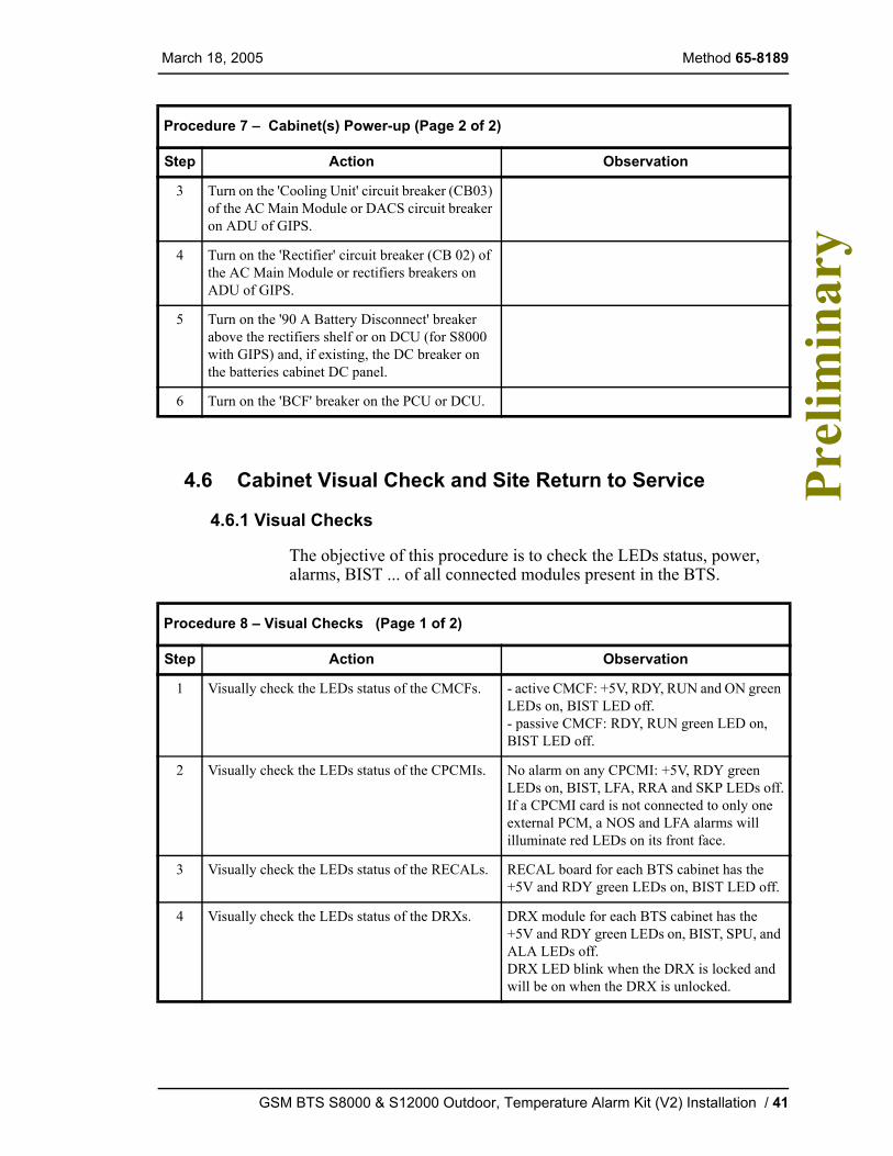
3 Turn on the 'Cooling Unit' circuit breaker (CB03) of the AC Main Module or DACS circuit breaker on ADU of GIPS.
4 Turn on the 'Rectifier' circuit breaker (CB 02) of the AC Main Module or rectifiers breakers on ADU of GIPS.
5 Turn on the '90 A Battery Disconnect' breaker above the rectifiers shelf or on DCU (for S8000 with GIPS) and, if existing, the DC breaker on the batteries cabinet DC panel.
6 Turn on the 'BCF' breaker on the PCU or DCU.
Procedure 8 – Visual Checks (Page 1 of 2)
Step Action Observation
1 Visually check the LEDs status of the CMCFs. - active CMCF: +5V, RDY, RUN and ON green LEDs on, BIST LED off.- passive CMCF: RDY, RUN green LED on, BIST LED off.
2 Visually check the LEDs status of the CPCMIs. No alarm on any CPCMI: +5V, RDY green LEDs on, BIST, LFA, RRA and SKP LEDs off.If a CPCMI card is not connected to only one external PCM, a NOS and LFA alarms will illuminate red LEDs on its front face.
3 Visually check the LEDs status of the RECALs. RECAL board for each BTS cabinet has the +5V and RDY green LEDs on, BIST LED off.
4 Visually check the LEDs status of the DRXs. DRX module for each BTS cabinet has the +5V and RDY green LEDs on, BIST, SPU, and ALA LEDs off.DRX LED blink when the DRX is locked and will be on when the DRX is unlocked.
Procedure 7 – Cabinet(s) Power-up (Page 2 of 2)
Step Action Observation
GSM BTS S8000 & S12000 Outdoor, Temperature Alarm Kit (V2) Installation / 41
Method 65-8189 March 18, 2005 P
relim
inar
y
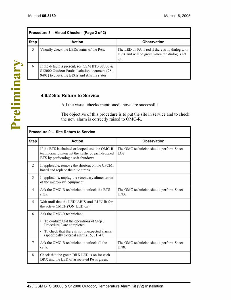
4.6.2 Site Return to Service
All the visual checks mentioned above are successful.
The objective of this procedure is to put the site in service and to check the new alarm is correctly raised to OMC-R.
5 Visually check the LEDs status of the PAs. The LED on PA is red if there is no dialog with DRX and will be green when the dialog is set up.
6 If the default is present, see GSM BTS S8000 & S12000 Outdoor Faults Isolation document (28-9401) to check the BISTs and Alarms status.
Procedure 9 – Site Return to Service
Step Action Observation
1 If the BTS is chained or looped, ask the OMC-R technician to interrupt the traffic of each dropped BTS by performing a soft shutdown.
The OMC technician should perform Sheet LO2
2 If applicable, remove the shortcut on the CPCMI board and replace the blue straps.
3 If applicable, unplug the secondary alimentation of the microwave equipment.
4 Ask the OMC-R technician to unlock the BTS sites.
The OMC technician should perform Sheet UN3.
5 Wait until that the LED 'ABIS' and 'RUN' lit for the active CMCF ('ON' LED on).
6 Ask the OMC-R technician:
• To confirm that the operations of Step 1 Procedure 2 are completed
• To check that there is not unexpected alarms (specifically external alarms 15, 31, 47)
7 Ask the OMC-R technician to unlock all the cells.
The OMC technician should perform Sheet UN8.
8 Check that the green DRX LED is on for each DRX and the LED of associated PA is green.
Procedure 8 – Visual Checks (Page 2 of 2)
Step Action Observation
42 / GSM BTS S8000 & S12000 Outdoor, Temperature Alarm Kit (V2) Installation
March 18, 2005 Method 65-8189
Pre
limin
ary
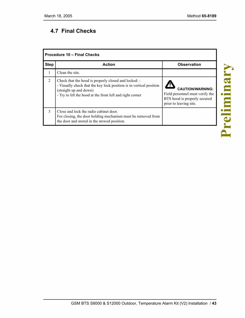
4.7 Final Checks
Procedure 10 – Final Checks
Step Action Observation
1 Clean the site.
2 Check that the hood is properly closed and locked: :- Visually check that the key lock position is in vertical position (straight up and down) - Try to lift the hood at the front left and right corner
CAUTION/WARNING: Field personnel must verify the BTS hood is properly secured prior to leaving site.
3 Close and lock the radio cabinet door.For closing, the door holding mechanism must be removed from the door and stored in the stowed position.
GSM BTS S8000 & S12000 Outdoor, Temperature Alarm Kit (V2) Installation / 43

Method 65-8189 March 18, 2005 P
relim
inar
y
5.0 ReferencesNone
44 / GSM BTS S8000 & S12000 Outdoor, Temperature Alarm Kit (V2) Installation
March 18, 2005 Method 65-8189
Pre
limin
ary
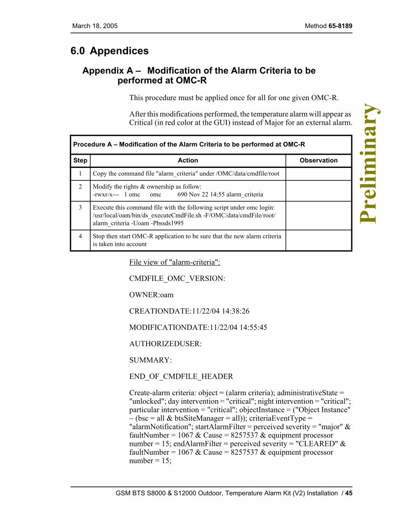
6.0 Appendices
Appendix A – Modification of the Alarm Criteria to be performed at OMC-R
This procedure must be applied once for all for one given OMC-R.
After this modifications performed, the temperature alarm will appear as Critical (in red color at the GUI) instead of Major for an external alarm.
File view of "alarm-criteria":
CMDFILE_OMC_VERSION:
OWNER:oam
CREATIONDATE:11/22/04 14:38:26
MODIFICATIONDATE:11/22/04 14:55:45
AUTHORIZEDUSER:
SUMMARY:
END_OF_CMDFILE_HEADER
Create-alarm criteria: object = (alarm criteria); administrativeState = "unlocked"; day intervention = "critical"; night intervention = "critical"; particular intervention = "critical"; objectInstance = ("Object Instance" ~ (bsc = all & btsSiteManager = all)); criteriaEventType = "alarmNotification"; startAlarmFilter = perceived severity = "major" & faultNumber = 1067 & Cause = 8257537 & equipment processor number = 15; endAlarmFilter = perceived severity = "CLEARED" & faultNumber = 1067 & Cause = 8257537 & equipment processor number = 15;
Procedure A – Modification of the Alarm Criteria to be performed at OMC-R
Step Action Observation
1 Copy the command file "alarm_criteria" under /OMC/data/cmdfile/root
2 Modify the rights & ownership as follow:-rwxr-x--- 1 omc omc 690 Nov 22 14:55 alarm_criteria
3 Execute this command file with the following script under omc login:/usr/local/oam/bin/ds_executeCmdFile.sh -F/OMC/data/cmdFile/root/alarm_criteria -Uoam -Pbssds1995
4 Stop then start OMC-R application to be sure that the new alarm criteria is taken into account
GSM BTS S8000 & S12000 Outdoor, Temperature Alarm Kit (V2) Installation / 45
Method 65-8189 March 18, 2005 P
relim
inar
y
Create-alarm criteria: object = (alarm criteria); administrativeState = "unlocked"; day intervention = "critical"; night intervention = "critical"; particular intervention = "critical"; objectInstance = ("Object Instance" ~ (bsc = all & btsSiteManager = all)); criteriaEventType = "alarmNotification"; startAlarmFilter = perceived severity = "major" & faultNumber = 1067 & Cause = 8257537 & equipment processor number = 31; endAlarmFilter = perceived severity = "CLEARED" & faultNumber = 1067 & Cause = 8257537 & equipment processor number = 31;Create-alarm criteria: object = (alarm criteria); administrativeState = "unlocked"; day intervention = "critical"; night intervention = "critical"; particular intervention = "critical"; objectInstance = ("Object Instance" ~ (bsc = all & btsSiteManager = all)); criteriaEventType = "alarmNotification"; startAlarmFilter = perceived severity = "major" & faultNumber = 1067 & Cause = 8257537 & equipment processor number = 47; endAlarmFilter = perceived severity = "CLEARED" & faultNumber = 1067 & Cause = 8257537 & equipment processor number = 47;
46 / GSM BTS S8000 & S12000 Outdoor, Temperature Alarm Kit (V2) Installation
March 18, 2005 Method 65-8189
Pre
limin
ary
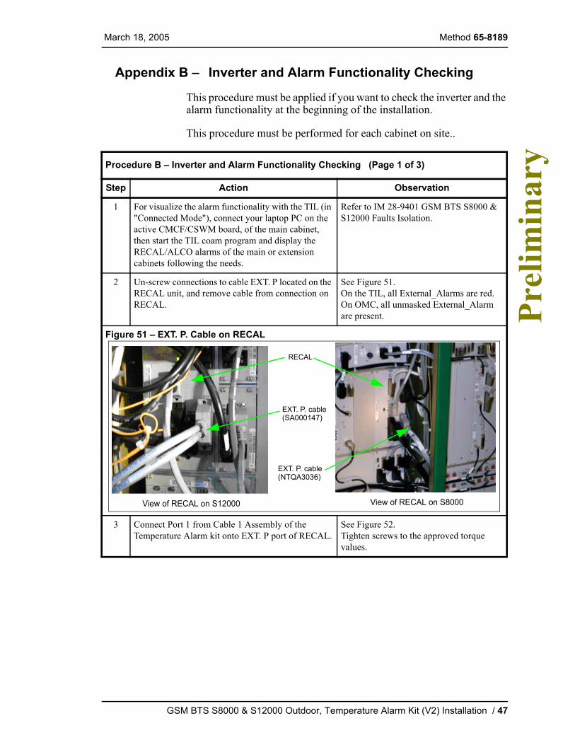
Appendix B – Inverter and Alarm Functionality Checking
This procedure must be applied if you want to check the inverter and the alarm functionality at the beginning of the installation.
This procedure must be performed for each cabinet on site..
Procedure B – Inverter and Alarm Functionality Checking (Page 1 of 3)
Step Action Observation
1 For visualize the alarm functionality with the TIL (in "Connected Mode"), connect your laptop PC on the active CMCF/CSWM board, of the main cabinet, then start the TIL coam program and display the RECAL/ALCO alarms of the main or extension cabinets following the needs.
Refer to IM 28-9401 GSM BTS S8000 & S12000 Faults Isolation.
2 Un-screw connections to cable EXT. P located on the RECAL unit, and remove cable from connection on RECAL.
See Figure 51.On the TIL, all External_Alarms are red.On OMC, all unmasked External_Alarm are present.
Figure 51 – EXT. P. Cable on RECAL
3 Connect Port 1 from Cable 1 Assembly of the Temperature Alarm kit onto EXT. P port of RECAL.
See Figure 52.Tighten screws to the approved torque values.
EXT. P. cable
RECAL
EXT. P. cable
View of RECAL on S12000 View of RECAL on S8000
(SA000147)
(NTQA3036)
GSM BTS S8000 & S12000 Outdoor, Temperature Alarm Kit (V2) Installation / 47
Method 65-8189 March 18, 2005 P
relim
inar
y
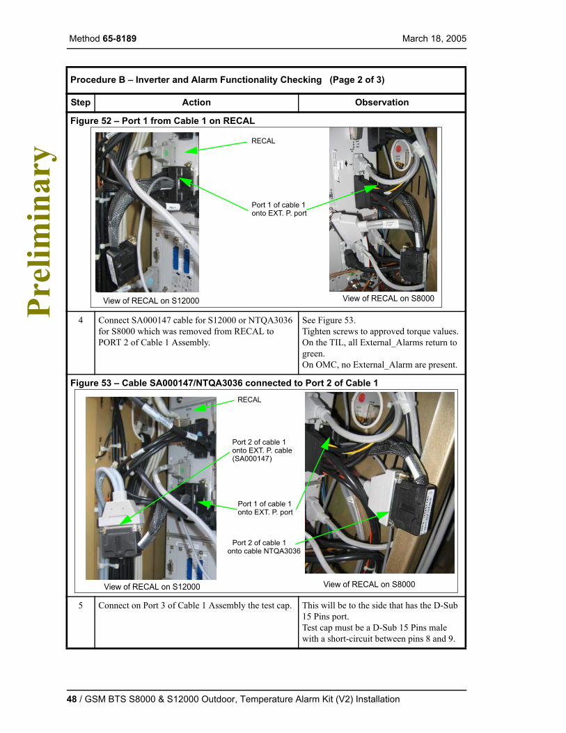
Figure 52 – Port 1 from Cable 1 on RECAL
4 Connect SA000147 cable for S12000 or NTQA3036 for S8000 which was removed from RECAL to PORT 2 of Cable 1 Assembly.
See Figure 53.Tighten screws to approved torque values.On the TIL, all External_Alarms return to green.On OMC, no External_Alarm are present.
Figure 53 – Cable SA000147/NTQA3036 connected to Port 2 of Cable 1
5 Connect on Port 3 of Cable 1 Assembly the test cap. This will be to the side that has the D-Sub 15 Pins port.Test cap must be a D-Sub 15 Pins male with a short-circuit between pins 8 and 9.
Procedure B – Inverter and Alarm Functionality Checking (Page 2 of 3)
Step Action Observation
Port 1 of cable 1
RECAL
onto EXT. P. port
View of RECAL on S12000 View of RECAL on S8000
Port 1 of cable 1
RECAL
onto EXT. P. port
Port 2 of cable 1onto EXT. P. cable(SA000147)
Port 2 of cable 1onto cable NTQA3036
View of RECAL on S12000 View of RECAL on S8000
48 / GSM BTS S8000 & S12000 Outdoor, Temperature Alarm Kit (V2) Installation
March 18, 2005 Method 65-8189
Pre
limin
ary
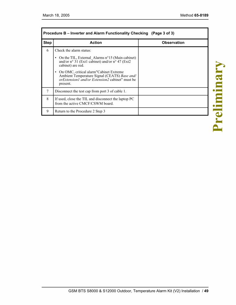
6 Check the alarm status:
• On the TIL, External_Alarms n°15 (Main cabinet) and/or n° 31 (Ext1 cabinet) and/or n° 47 (Ext2 cabinet) are red.
• On OMC, critical alarm"Cabinet Extreme Ambient Temperature Signal (CEATS) Base and/orExtension1 and/or Extension2 cabinet" must be present.
7 Disconnect the test cap from port 3 of cable 1.
8 If used, close the TIL and disconnect the laptop PC from the active CMCF/CSWM board.
9 Return to the Procedure 2 Step 3
Procedure B – Inverter and Alarm Functionality Checking (Page 3 of 3)
Step Action Observation
GSM BTS S8000 & S12000 Outdoor, Temperature Alarm Kit (V2) Installation / 49
Method 65-8189 March 18, 2005 P
relim
inar
y
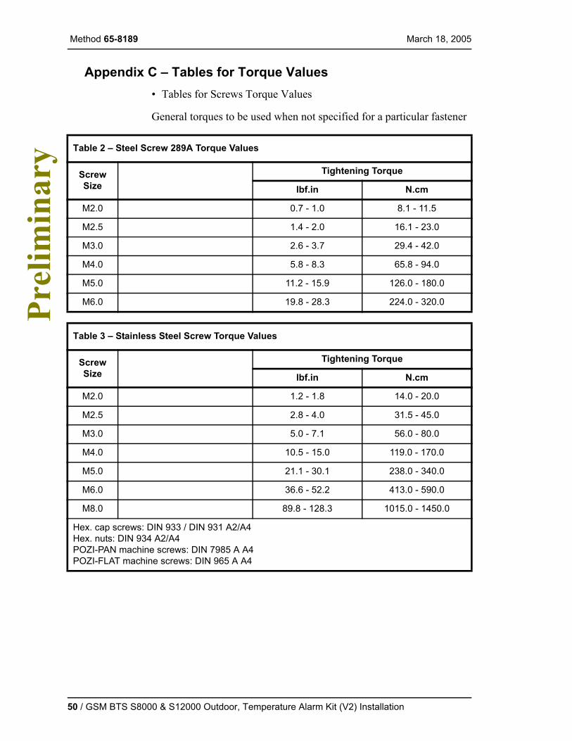
Appendix C – Tables for Torque Values• Tables for Screws Torque Values
General torques to be used when not specified for a particular fastener
Table 2 – Steel Screw 289A Torque Values
Screw Size
Tightening Torque
lbf.in N.cm
M2.0 0.7 - 1.0 8.1 - 11.5
M2.5 1.4 - 2.0 16.1 - 23.0
M3.0 2.6 - 3.7 29.4 - 42.0
M4.0 5.8 - 8.3 65.8 - 94.0
M5.0 11.2 - 15.9 126.0 - 180.0
M6.0 19.8 - 28.3 224.0 - 320.0
Table 3 – Stainless Steel Screw Torque Values
Screw Size
Tightening Torque
lbf.in N.cm
M2.0 1.2 - 1.8 14.0 - 20.0
M2.5 2.8 - 4.0 31.5 - 45.0
M3.0 5.0 - 7.1 56.0 - 80.0
M4.0 10.5 - 15.0 119.0 - 170.0
M5.0 21.1 - 30.1 238.0 - 340.0
M6.0 36.6 - 52.2 413.0 - 590.0
M8.0 89.8 - 128.3 1015.0 - 1450.0
Hex. cap screws: DIN 933 / DIN 931 A2/A4Hex. nuts: DIN 934 A2/A4POZI-PAN machine screws: DIN 7985 A A4POZI-FLAT machine screws: DIN 965 A A4
50 / GSM BTS S8000 & S12000 Outdoor, Temperature Alarm Kit (V2) Installation

March 18, 2005 Method 65-8189
Pre
limin
ary
• Tables for RF Connections Torque Values
General torques to be used when not specified for a particular fastener
Table 4 – Terminal Strips Torque Values (Data from CS154.07)
Screw Size Major Dia. (inches)
Tightening Torque
lbf.in N.cm
#2 0.086 0.7 - 1.2 8.1 - 14.1
#4 0.112 1.3 - 2.0 14.1 - 22.6
#5 0.125 1.5 - 3.0 17.0 - 33.9
#6 0.138 2.0 - 4.0 22.6 - 45.2
#8 0.164 4.0 - 8.0 45.2 - 90.4
#10 0.190 5.0 - 10.0 56.5 - 113.0
Table 5 – Miscellaneous Torque Values
TypeTightening Torque
lbf.in N.cm
#4-40 screwlock 1.3 - 2.0 14.1 - 22.6
#4-40 connector screw 1.3 - 2.0 14.1 - 22.6
Table 6 – RF Connections Torque Values
Type Tool NumberTightening Torque
lbf.in N.m
SMA T002578 7.08 - 10.6 0.80 - 1.20
GSM BTS S8000 & S12000 Outdoor, Temperature Alarm Kit (V2) Installation / 51

Method 65-8189 March 18, 2005 P
relim
inar
y
Appendix D – GlossaryABBREVIATIONS DEFINITIONS
ADU AC Distribution Unit
BIST Built-In Self Test
BTS Base Transceiver Station
CB Circuit Breaker
CBCF Compact Base Common Functions
DACS Direct Ambient Climatic System
DCU DC Control Unit
GIPS GSM Integrated Power Supply
GSM Global System for Mobile telecommunication
IM Installation Method
ISM Installation Safety Manual
LED Light Emitting Diode
NOS NO Signal
OMC Operating & Maintenance Center
PCM Pulse Coded Modulation
PCU Power Control Unit
PWR PoWeR
RDY ReaDY
RECAL REmote Control and ALarm
52 / GSM BTS S8000 & S12000 Outdoor, Temperature Alarm Kit (V2) Installation
March 18, 2005 Method 65-8189
Pre
limin
ary
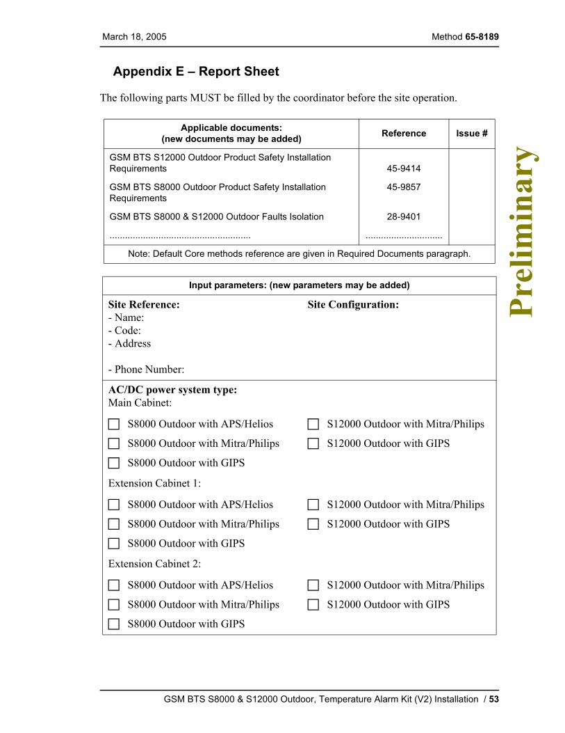
Appendix E – Report Sheet
The following parts MUST be filled by the coordinator before the site operation.
Applicable documents:(new documents may be added) Reference Issue #
GSM BTS S12000 Outdoor Product Safety Installation Requirements 45-9414
GSM BTS S8000 Outdoor Product Safety Installation Requirements
45-9857
GSM BTS S8000 & S12000 Outdoor Faults Isolation 28-9401
....................................................... ..............................
Note: Default Core methods reference are given in Required Documents paragraph.
Input parameters: (new parameters may be added)
Site Reference: - Name:- Code:- Address
- Phone Number:
Site Configuration:
AC/DC power system type:Main Cabinet:
S8000 Outdoor with APS/Helios
S8000 Outdoor with Mitra/Philips
S8000 Outdoor with GIPS
S12000 Outdoor with Mitra/Philips
S12000 Outdoor with GIPS
Extension Cabinet 1:
S8000 Outdoor with APS/Helios
S8000 Outdoor with Mitra/Philips
S8000 Outdoor with GIPS
S12000 Outdoor with Mitra/Philips
S12000 Outdoor with GIPS
Extension Cabinet 2:
S8000 Outdoor with APS/Helios
S8000 Outdoor with Mitra/Philips
S8000 Outdoor with GIPS
S12000 Outdoor with Mitra/Philips
S12000 Outdoor with GIPS
GSM BTS S8000 & S12000 Outdoor, Temperature Alarm Kit (V2) Installation / 53
Method 65-8189 March 18, 2005 P
relim
inar
y
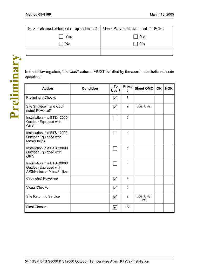
In the following chart, ‘To Use?’ column MUST be filled by the coordinator before the site operation.
BTS is chained or looped (drop and insert):
Yes
No
Micro Wave links are used for PCM:
Yes
No
Action Condition To Use ?
Proc. # Sheet OMC OK NOK
Preliminary Checks 1
Site Shutdown and Cabi-net(s) Power-off
2 LO2, UN2.
Installation in a BTS 12000 Outdoor Equipped with GIPS
3
Installation in a BTS 12000 Outdoor Equipped with Mitra/Philips
4
Installation in a BTS S8000 Outdoor Equipped with GIPS
5
Installation in a BTS S8000 Outdoor Equipped with APS/Helios or Mitra/Philips
6
Cabinet(s) Power-up 7
Visual Checks 8
Site Return to Service 9 LO2, UN3, UN8.
Final Checks 10
54 / GSM BTS S8000 & S12000 Outdoor, Temperature Alarm Kit (V2) Installation

March 18, 2005 Method 65-8189
Pre
limin
ary
This folio MUST be filled by the commissioner during the site operation.
Additional results:System release: V....Ed....Serial Numbers: Main Cabinet: ................
Extension Cabinet 1: ...............Extension Cabinet 2: ...............
Comments
Sign off
Last Page
Tools Type Serial Number Next Calibration Date
SMA torque wrench
Coordinator Commissioner Customer representative
Company name
Functions
Name
Signature
Date
GSM BTS S8000 & S12000 Outdoor, Temperature Alarm Kit (V2) Installation / 55