NORSOK M-101 (Ed. 2011)_Structural Steel Fabrication
62
This NORSOK standard is developed with broad petroleum industry participation by interested parties in the Norwegian petroleum industry and is owned by the Norwegian petroleum industry represented by The Norwegian Oil Industry Association (OLF) and The Federation of Norwegian Industry. Please note that whilst every effort has been made to ensure the accuracy of this NORSOK standard, neither OLF nor The Federation of Norwegian Industry or any of their members will assume liability for any use thereof. Standards Norway is responsible for the administration and publication of this NORSOK standard. Standards Norway Telephone: + 47 67 83 86 00 Strandveien 18, P.O. Box 242 Fax: + 47 67 83 86 01 N-1326 Lysaker Email: [email protected] NORWAY Website: www.standard.no/petroleum Copyrights reserved NORSOK STANDARD M-101 Edition 5, October 2011 Structural steel fabrication Provided by Standard Online AS for Ignatios+Staboulis 2014-06-23
-
Upload
ignatios-staboulis -
Category
Documents
-
view
2.977 -
download
67
description
NORSOK M-101 (Ed. 2011)_Structural Steel Fabrication
Transcript of NORSOK M-101 (Ed. 2011)_Structural Steel Fabrication

This NORSOK standard is developed with broad petroleum industry participation by interested parties in the Norwegian petroleum industry and is owned by the Norwegian petroleum industry represented by The Norwegian Oil Industry Association (OLF) and The Federation of Norwegian Industry. Please note that whilst every effort has been made to ensure the accuracy of this NORSOK standard, neither OLF nor The Federation of Norwegian Industry or any of their members will assume liability for any use thereof. Standards Norway is responsible for the administration and publication of this NORSOK standard.
Standards Norway Telephone: + 47 67 83 86 00 Strandveien 18, P.O. Box 242 Fax: + 47 67 83 86 01 N-1326 Lysaker Email: [email protected] NORWAY Website: www.standard.no/petroleum
Copyrights reserved
NORSOK STANDARD M-101 Edition 5, October 2011
Structural steel fabrication
Pro
vide
d by
Sta
ndar
d O
nlin
e A
S fo
r Ig
natio
s+S
tabo
ulis
201
4-06
-23

Pro
vide
d by
Sta
ndar
d O
nlin
e A
S fo
r Ig
natio
s+S
tabo
ulis
201
4-06
-23

NORSOK standard M-101 Edition 5, October 2011
NORSOK standard Page 3 of 62
Foreword 5
Introduction 5
1 Scope 6
2 Normative and informative references 6 2.1 Normative references 6 2.2 Informative references 7
3 Terms, definitions and abbreviations 7 3.1 Terms and definitions 7 3.2 Abbreviations 7
4 Selection of steels 8 4.1 Design classes 8 4.2 Selection of steel quality level 8
5 Qualification of welding procedures and welders 8 5.1 Welding procedure specification (WPS) 8 5.2 Qualification of welding procedures 8 5.3 Welding procedure qualification record (WPQR) - Range of approval 9 5.4 Examination of the test weld 10 5.5 Welder and welding operators qualifications 12
6 Fabrication and welding requirements 12 6.1 General 12 6.2 Drawings for fabrication 12 6.3 Welding coordination 12 6.4 Welding inspection and qualification of welding inspectors 13 6.5 Forming 13 6.6 Assembly 13 6.7 Preparation for coatings 15 6.8 Preparation and fit-up of weld bevels 15 6.9 Welding processes 15 6.10 Welding consumables 15 6.11 Preheat and interpass temperature 15 6.12 Production welding 16 6.13 Post weld heat treatment (PWHT) 16 6.14 Grinding 17 6.15 Peening 17
7 Production tests 17
8 Fabrication tolerances 17
9 Non-destructive testing (NDT) 17 9.1 General 17 9.2 Qualification of non-destructive testing (NDT) operators 18 9.3 Extent of visual examination and non-destructive testing (NDT) 19 9.4 Visual examination and finish of welds 20 9.5 Radiographic testing 20 9.6 Ultrasonic testing 20 9.7 Magnetic particle and penetrant testing 21 9.8 Acceptance criteria 21
10 Repair 24 10.1 Definitions 24 10.2 Correction of welds containing defects 25 10.3 Repair by welding 25 10.4 Repair welding procedure 25 10.5 Correction of distortion 25
Annex A (Informative) Details for high fatigue utilisation 26
Annex B (Informative) Correlation between steel quality level, MDS number and steel grade/designations 28
Pro
vide
d by
Sta
ndar
d O
nlin
e A
S fo
r Ig
natio
s+S
tabo
ulis
201
4-06
-23

NORSOK standard M-101 Edition 5, October 2011
NORSOK standard Page 4 of 62
Annex C (Normative) Qualification of welding consumables by data sheets 30
Annex D (Normative) Welding consumable documented by batch testing 32
Annex E (Normative) Fabrication tolerances 33
Annex F (Informative) Weld inspection, typical check points 57
Annex G (Normative) Components in stainless steel and Ni-alloys 59
Pro
vide
d by
Sta
ndar
d O
nlin
e A
S fo
r Ig
natio
s+S
tabo
ulis
201
4-06
-23

NORSOK standard M-101 Edition 5, October 2011
NORSOK standard Page 5 of 62
Foreword The NORSOK standards are developed by the Norwegian petroleum industry to ensure adequate safety, value adding and cost effectiveness for petroleum industry developments and operations. Furthermore, NORSOK standards are, as far as possible, intended to replace oil company specifications and serve as references in the authorities’ regulations. The NORSOK standards are normally based on recognised international standards, adding the provisions deemed necessary to fill the broad needs of the Norwegian petroleum industry. Where relevant, NORSOK standards will be used to provide the Norwegian industry input to the international standardisation process. Subject to development and publication of international standards, the relevant NORSOK standard will be withdrawn. The NORSOK standards are developed according to the consensus principle generally applicable for most standards work and according to established procedures defined in NORSOK A-001. The NORSOK standards are prepared and published with support by The Norwegian Oil Industry Association (OLF), The Federation of Norwegian Industry, Norwegian Shipowners’ Association and The Petroleum Safety Authority Norway. NORSOK standards are administered and published by Standards Norway. Annex A, B and F are informative. Annexes C, D, E and G are normative.
Introduction Edition 5 of this NORSOK standard has been necessary due to an extensive change in referenced international standards. In addition new annexes have been included. Some corrections and improvements have also been implemented
Pro
vide
d by
Sta
ndar
d O
nlin
e A
S fo
r Ig
natio
s+S
tabo
ulis
201
4-06
-23

NORSOK standard M-101 Edition 5, October 2011
NORSOK standard Page 6 of 62
1 Scope This NORSOK standard covers the requirements for fabrication and inspection of offshore steel structures with SMYS < 500 MPa and with a minimum design temperature down to -14 C. NOTE 1 Lower minimum design temperatures require project specific evaluations. For special application steels with SMYS up
to 690 MPa may be used. NOTE 2 For highly fatigue utilized structures, more severe requirements may apply, and these will be shown on the design
drawings.
2 Normative and informative references The following standards include provisions and guidelines which, through reference in this text, constitute provisions and guidelines of this NORSOK standard. Latest issue of the references shall be used unless otherwise agreed. Other recognized standards may be used provided it can be shown that they meet the requirements of the referenced standards.
2.1 Normative references BS 7448, Part 1, Fracture mechanics toughness tests BS 7910, Guide on methods for assessing the acceptability of flaws in fusion welded
structures DNV RP D404, Unstable fracture IIW International Welder, Minimum requirements for education, training and qualification of welding
personnel EN 287-1, Qualification test of welders – Fusion welding – Part 1: Steels EN 473, Qualification and certification of NDT personnel – General principles EN 1011- (all parts), Welding – Recommendation for welding of metallic materials - (all parts) EN 1011-3, Welding – Recommendation for welding of metallic materials – Part 3: Arc
welding of stainless steels EN 1090-1:2009 + EN 1090-1:2009/AC:2010, Execution of steel structures and aluminium structures – Part 1: Requirements
for conformity assessment of structural components EN 10204, Metallic products – Types of inspection documents EN 10225, Weldable structural steels for fixed offshore structures – Technical delivery
conditions ISO 2553, Welded, brazed and soldered joints – Symbolic representation on drawings ISO 3452-1, Non-destructive testing – Penetrant testing – Part 1: General principles ISO 3690, Welding – Determination of hydrogen indeposited weld metal arising from the
use of covered electrodes for welding mild and low alloy steels ISO 3834-2, Quality requirements for welding of metallic materials – Part 2: Comprehensive
quality requirements ISO 6520-1, Welding and allied processes – Classification of geometric imperfections in
metallic materials – Part 1: Fusion welding ISO 6847, Welding consumables – Deposition of a weld metal pad for chemical analysis ISO 8062:1994, Castings – System of dimensional tolerances and machining allowances ISO 9016, Destructive tests on welds in metallic materials – impact tests – Test specimen
location, notch orientation and examination ISO 9606-4, Approval testing of welders – Fusion welding – Part 4: Nickel and nickel alloys ISO 9712, Non-destructive testing – Qualification and certification of personnel ISO 14731, Welding coordination – Tasks and responsibilities ISO 14732, Welding personnel – Approval testing of welding operators for fusion welding ISO 15607, Specification and qualification of welding procedures for metallic materials –
General rules ISO 15609-1, Specification and qualification of welding procedures for metallic materials –
Welding procedure specification – Part 1: Arc welding ISO 15614-1, Specification and qualification of welding procedures for metallic materials –
Welding procedure test – Part 1: Arc and gas welding of steels and arc welding of nickel and nickel alloys
ISO/TR 15608, Welding – Guidelines for a metallic materials grouping system
Pro
vide
d by
Sta
ndar
d O
nlin
e A
S fo
r Ig
natio
s+S
tabo
ulis
201
4-06
-23

NORSOK standard M-101 Edition 5, October 2011
NORSOK standard Page 7 of 62
ISO 15792-1, Welding consumables – Test methods – Part 1: Test methods for all-weld metal test specimens in steel, nickel and nickel alloys
ISO 17025, General requirements for the competence of testing and calibration laboratories ISO 17636, Non-destructive testing of welds – Radiographic testing of fusion-welded ISO 17637, Non-destructive testing of welds – Visual testing of fusion welded joints. ISO 17638, Non-destructive testing of welds – Magnetic particle testing. ISO 17640, Non-destructive testing of welds – Ultrasonic testing of welded joints. ISO 22825, Non-destructive testing of welds – Ultrasonic testing – Testing of welds in
austenitic steels and nickel-based alloys NORSOK M-120, Material data sheets for structural steel NORSOK N-004, Design of steel structures NORSOK M-601, Welding and inspection of piping NS 477, Welding. Rules for approval of welding inspectors
2.2 Informative references EN 10025-(all parts), Hot rolled products of structural steels – (all parts) EN 10210-(all parts), Hot finished structural hollow sections of non-alloy and fine grain steels – (all
parts) EN 10219-(all parts), Cold formed welded structural hollow sections of non-alloy and fine grain steels
– (all parts) ISO 3834-3, Quality requirements for welding of metallic materials – Part 3: Standard quality
requirements
3 Terms, definitions and abbreviations For the purposes of this NORSOK standard, the following terms, definitions and abbreviations apply.
3.1 Terms and definitions 3.1.1 shall verbal form used to indicate requirements strictly to be followed in order to conform to this NORSOK standard and from which no deviation is permitted, unless accepted by all involved parties 3.1.2 should verbal form used to indicate that among several possibilities one is recommended as particularly suitable, without mentioning or excluding others, or that a certain course of action is preferred but not necessarily required 3.1.3 may verbal form used to indicate a course of action permissible within the limits of this NORSOK standard 3.1.4 can verbal form used for statements of possibility and capability, whether material, physical or casual
3.2 Abbreviations AFC approved for construction BS British Standard CEV carbon equivalent value (IIW, International Institute of Welding Formula
CEV 1556CuNiVMoCrMnC
CTOD crack tip opening displacement DAC distance amplitude curve DNV Det Norske Veritas EN (pr EN) European Standard (proposal for EN) EWF European Welding Federation FCAW flux cored arc welding P
rovi
ded
by S
tand
ard
Onl
ine
AS
for
Igna
tios+
Sta
boul
is 2
014-
06-2
3

NORSOK standard M-101 Edition 5, October 2011
NORSOK standard Page 8 of 62
FSH full screen height HAZ heat affected zone HDM hydrogen content, deposit metal IIW International Institute of Welding IW International Welder IWT International Welding Technologist IWE International Welding Engineer IWI International Welding Inspector ISO International Organization for Standardization MDS material data sheet MSF main support frame MT magnetic particle testing NDT non destructive testing OD outside diameter Pcm carbon equivalent (cold cracking susceptibility)
Pcm BVMoNiCrCuMnSiC 51015602030
PT penetrant testing PWHT post weld heat treatment RT radiographic testing SAW submerged arc welding SMYS specified minimum yield strength SQL steel quality level SS stainless steel UT ultrasonic testing VT visual testing WPS welding procedure specification WPQR welding procedure qualification record
4 Selection of steels
4.1 Design classes The design classes will be decided by the designer and shall form the basis for selection of SQL. Reference is made to NORSOK N-004.
4.2 Selection of steel quality level The steel quality level will be decided by the designer in compliance with NORSOK N-004. Annex B gives the correlation between the steel quality levels I, II, III and IV, and designations on equivalent steels given in NORSOK M-120. Selection of a better steel quality level in fabrication than the minimum required by the designer shall not lead to more stringent requirements in fabrication.
5 Qualification of welding procedures and welders
5.1 Welding procedure specification (WPS) Specification and qualification of welding procedures for metallic materials shall be in accordance with ISO 15607. WPS shall be established in accordance with ISO 15609-1.
5.2 Qualification of welding procedures Welding procedures used for structures requiring steel quality level I and II for all strength levels and steel quality level III for SMYS 355 MPa shall be qualified in accordance with ISO 15614-1 and the additional requirements in this NORSOK standard.
Pro
vide
d by
Sta
ndar
d O
nlin
e A
S fo
r Ig
natio
s+S
tabo
ulis
201
4-06
-23

NORSOK standard M-101 Edition 5, October 2011
NORSOK standard Page 9 of 62
The qualification is primarily valid for the workshop performing the welding tests, and other workshops under the same technical and quality management. It may also be transferred to and used by a subcontractor, provided the principles of ISO 3834-2 and ISO 14731 are implemented and documented. Requirements to components in stainless steel and Ni-alloys are given in Annex G. The WPQR documentation shall include the material certificates for the base material and filler materials applied in the weld qualification test. PWHT report and chart shall be included in the WPQR.
5.3 Welding procedure qualification record (WPQR) - Range of approval
5.3.1 For welding of steels in all strength classes The WPQR is valid within the limitations specified in ISO 15614-1, with the following clarifications and modifications: a) control of heat input according to ISO 15614-1, 8.4.8, shall apply. If an approval testing have been
performed at both a high and a low heat input level (all specified mechanical testing to be performed for both high and low heat input), then all intermediate heat inputs are also qualified;
b) when the steel to be welded has a Pcm 0,21, or a carbon content C 0,13 %, then an increase of more than 0,02 Pcm units or 0,03 CEV (IIW formula) units over the value on the approval test shall require a new qualification test;
c) a change from wrought (rolled, forged) steel to cast steel or converse; d) for all strength levels for SQL I and II and for SMYS > 400 MPa for SQL III, a change in delivery condition
(normalised, thermomechanically controlled processed or quenched and tempered); e) a change in microalloying element or manufacturing technique for steel with SMYS 400 MPa; f) a decrease in groove angle of more than 10° . For groove angles less than 30°, the limitation is +20°/- 0°; g) a qualification of fillet welds carried out on plate thickness equal to or greater than 30 mm, applies for all
plate and throat thicknesses. Single layer fillet welds qualifies multi-layer, but not the converse; h) qualification of WPS with manual welding methods 135 and 136 applies also for partly mechanized and
mechanized welding, but not vice versa; i) CTOD testing shall be included in the qualification of welding procedures for weldments with a plate
thickness above 50 mm for all strength levels for steel quality level I and II and for SMYS > 400 MPa for steel quality level III. CTOD testing shall be included in the qualification of welding procedures for weldments with a plate thickness below and equal 50 mm if requested by the designer for the specified steel quality level. CTOD testing shall be executed from as welded and PWHT weld assemblies as applicable, covering the following combined conditions:
1) full penetration buttweld with K-, or half V -groove as deemed most representative for the actual
fabrication. V and X groove are acceptable for weld metal test; 2) a welding procedure representing the maximum heat input to be used in fabrication; 3) maximum joint thickness (within 10 %).
Assemblies shall be made and tested for the actual combination of steel manufacturer, welding process and welding consumable (brand) used, except welding consumables used for root passes only, provided these are removed completely by gouging and grinding.
NOTE The changes specified in d) and e) above need not require re-qualification if HAZ properties for the material to be welded have been documented from the steel manufacturer for relevant thicknesses and heat input ranges. If sufficient documentation from the steel manufacturer is not available, a change of material shall require re-qualification of a reduced number of procedures. The number of procedures to be re-qualified shall be sufficient to verify that the HAZ properties of the new material is comparable with that used for the previous qualifications.
5.3.2 For welding of steels with SMYS 500 MPa In addition to the requirements given in 5.3.1 the following additional requirements apply for welding of steels with SMYS > 500 MPa: a) a change in steel manufacturer; b) CTOD testing as described in 5.3.1 i) shall be executed for thicknesses above 30 mm; c) stress relieving if required/specified by designer.
Pro
vide
d by
Sta
ndar
d O
nlin
e A
S fo
r Ig
natio
s+S
tabo
ulis
201
4-06
-23

NORSOK standard M-101 Edition 5, October 2011
NORSOK standard Page 10 of 62
5.4 Examination of the test weld
5.4.1 General The type and number of tests shall be in accordance with Table 1. Testing shall be performed in accordance with ISO 15614-1 and the additional requirements given below. The test weld shall be 100 % examined for both surface and volumetric defects with the relevant NDT methods. The soundness of the weld shall comply with Clause 9. Test laboratories shall have a quality system in compliance with ISO 17025 or equivalent.
Table 1 Type and number of tests
Mechanical testing
Joint configuration
Joint thickness
mm
Tensile test
Bend tests a
Charpy V-notch tests
Hardness and
macro e
CTOD
Buttwelds (Tubulars and plates)
t ≤ 50 t 50
2 2
4 4
4 sets 6 sets
1 1
See 5.3.1 i), 5.3.2 b) and 5.4.4
T-joints (plates) d
t ≤ 50 t 50
c c
4 sets b 6 sets
2 2
f
Tubular joints d t ≤ 50 t 50
c c
4 sets b 6 sets
2 2
Fillet welds All 2 a Bend tests shall consist of 2 face and 2 root bend specimen for t < 12 mm and 4 side bend
specimens for t 12 mm. b If the dimensions of the joint does not allow Charpy V-notch testing, the Charpy V-notch
properties shall be documented on a butt weld joint made with the same consumable and same base material, and welding parameters and thickness within the range qualified for the joint.
c It shall be documented on a butt weld test that the welding consumable used will have sufficient tensile strength.
d T-joints on plates qualify for tubular joints, and vice versa. e For welds on submerged structures with cathodic protection, the hardness limits in NORSOK M-
001 shall apply in addition to the requirements of ISO 15614-1. f For T-joints with t > 50 mm, CTOD testing shall be documented on a buttweld.
5.4.2 Charpy V-notch testing Sampling of Charpy V-notch impact tests shall be carried out in accordance with ISO 9016, with the notch in the positions listed below. All specimens shall be machined with the notch through the thickness, 2 mm below the surface of the material. Designation in parenthesis refers to Figure 1 and Table 2 in ISO 9016. Notch in centre of weld (VWT 0/2). Notch in fusion line (VHT 0/2). Notch in HAZ, 2 mm from fusion line (VHT 2/2). Notch in HAZ, 5 mm from fusion line (VHT 5/2).
For welds with a joint thickness T 50 mm or more, two additional sets of Charpy V-notch tests shall be taken from the root area, with the notch in the following positions: notch in centre of weld (VWT 0/b); notch in fusion line (VHT 0/b).
The test temperature and energy requirements shall comply with Table 2.
Pro
vide
d by
Sta
ndar
d O
nlin
e A
S fo
r Ig
natio
s+S
tabo
ulis
201
4-06
-23

NORSOK standard M-101 Edition 5, October 2011
NORSOK standard Page 11 of 62
Table 2 Charpy impact test temperatures and energy requirements for welding procedure qualifications.
Material Steel quality level
thickness
I II III
(mm) SMYS 400
°C
400< SMYS
500 °C
SMYS 500
°C
SMYS 400
°C
400< SMYS
500 °C
SMYS 500
°C
355 SMYS
500 °C
SMYS 500
°C
t 12 0 -20 -20 0 -0 -20 -0 0 12 < t 25 -20 -40 -40 0 -20 -40 0 -20 25 < t 50 -40 -40 -40 -20 -40 -40 -20 -40
t > 50 -40 -40 -40 -40 -40 -40 -40 -40 Energy requirement a
36 J 42 J 60 J 27 J 42 J 60 J 27 J 42 J
a The minimum average value is given in the table. No individual value shall be less than 70 % of the
minimum average value. Reduction factors of energy requirements for subsize specimens shall be 5/6 for 7,5 mm and 2/3 for 5 mm.
5.4.3 Transverse tensile testing Testing shall be carried out in accordance with ISO 15614-1. The fracture shall be located outside the weld metal, i.e. maximum 20 % of the fracture surface shall consist of weld metal/HAZ.
5.4.4 Crack tip opening displacement (CTOD) testing The CTOD-technique with the Bx2B through-thickness notched type specimen according to BS 7448, Part 1, should be used. Three valid test specimens shall be obtained for each test position. CTOD-testing of welds shall be carried out with the fatigue notch tip positioned in the coarse grained region of the heat affected zone and in the weld metal. For HAZ, determination of the actual location of the fatigue crack tip shall be performed after testing, see EN 10225. NOTE Test assemblies may be given hydrogen diffusion treatment prior to testing, and specimens may be precompressed. If not specified otherwise, the test temperature for design temperature down to -14 °C shall be -10 °C for splash zone or above, 0 °C for submerged parts.
Other test temperature may be prescribed by the designer. The requirement for minimum CTOD value shall be prescribed by the designer. If not specified, the requirement for minimum CTOD value shall be as for the steel purchase order. CTOD-testing of HAZ can be omitted if relevant CTOD properties in HAZ have been documented previously in accordance with requirements in this NORSOK standard, provided the requirements for the essential variables are met. CTOD-testing of weld metal can be omitted if relevant CTOD properties in weld metal have been documented previously in accordance with requirements in this NORSOK standard, provided the requirements for the essential variables are met. The required fracture toughness level shall be decided in design for joints when steel quality level I and II are required. Testing is normally not requested for structures with plate thickness below 40 mm for SMYS 500 MPa or for structures with plate thickness below 25 mm for SMYS > 500 MPa.
Pro
vide
d by
Sta
ndar
d O
nlin
e A
S fo
r Ig
natio
s+S
tabo
ulis
201
4-06
-23

NORSOK standard M-101 Edition 5, October 2011
NORSOK standard Page 12 of 62
5.5 Welder and welding operators qualifications The welders shall be certified by an accredited body according to EN 287-1 and/or ISO 9606-4. Welding operators shall be certified according to ISO 14732. For tack welders, an internal test according with EN 287-1 and/or ISO 9606-4 is accepted without use of 3rd part. For welding in inspection category C, D and E, diploma as IW-International Welder (fillet- plate-pipe welder) within actual welding method and material may be accepted, see IIW, Minimum requirements for the education, training, examination and qualification of welding personnel. For welding of single sided acute angled tubular joints with < 70º, welders shall be qualified with a realistic joint, representing the minimum angle to be used in production.
6 Fabrication and welding requirements
6.1 General All welding work shall be according to recommendations given in relevant part of the EN 1011-series. The manufacturer shall have an implemented and documented quality system according with ISO 3834-2. For fabrication of structural steel in inspection category D and/or E, ISO 3834-3 may be accepted (used). All types of inspection/examination shall be performed by personnel other than those performing and being responsible for the production work. The fabricator shall apply a weld numbering system for identification on all shop drawings and as reference in all documentation.
6.2 Drawings for fabrication Symbolic presentation of welds shall be according to ISO 2553. Welds in inspection category A and B shall have unique weld number. Welds in inspection category C,D and E may be group numbered, but only within the same node/essential member and same drawing sheet. The shop drawings shall have enough information to enable correct selection of WPS. The following information shall be used as relevant: material type/grade and grouping number (ISO/TR 15608); dimension (outside diameter and wall thickness); PWHT requirements, if relevant; required toe grinding; etc.
6.3 Welding coordination All welding coordination shall be according to ISO 14731. The manufacturer shall appoint a responsible authorized welding coordinator. The responsible welding coordinator shall be qualified as an IWE, see ISO 14731, Annex A. The responsible welding coordinator may delegate welding coordination activities at fabrications sites to an IWT, see ISO 14731. If only fabrication/welding in inspection category D and/or E, an IWT may be accepted. All other personnel who are carrying out one or more welding activities according to ISO 14731, Annex B, are welding coordinators. The level of technical knowledge, tasks, responsibility and authority shall be identified for each person/function in a job description.
Pro
vide
d by
Sta
ndar
d O
nlin
e A
S fo
r Ig
natio
s+S
tabo
ulis
201
4-06
-23

NORSOK standard M-101 Edition 5, October 2011
NORSOK standard Page 13 of 62
6.4 Welding inspection and qualification of welding inspectors Welding inspector’s tasks and responsibilities is to be familiar with all standards, rules and specifications, and continuously verify that all requirements and adequate parts in ISO 3834-2 are implemented and followed. Welding inspection shall be performed before, during and after welding according to typical check points listed in Annex F. All inspections shall be reported to the responsible welding coordinator. The inspection frequency shall be sufficient to report weekly quality status during fabrication based on welding inspection reports. Prior to fabrication start-up, contractor shall implement a system for recording of quality status. Causes for non-conformance shall be immediately investigated and corrective action shall be taken to prevent further occurrence. Non-conformance shall require documented investigation/action by the responsible welding coordinator. Welding inspectors shall be qualified according to NS 477 or EWF/IIW rules for approval of IWI-International Welding Inspector
6.5 Forming Cold forming of steel (i.e. forming below 250 C) shall be carried out within the deformation range recommended by the steel manufacturer. For steel quality level I and II, the deformation limit without documentation of mechanical properties is 5 %. If the deformation is more than the above given limits, either heat treatment shall be performed, or strain ageing tests shall be carried out according to the following requirements: the material shall be permanently strained locally to the actual deformation; the material shall be artificially aged at 250 C for 1 h; one set of 3 impact test specimens shall be tested from the base material in the strained plus artificially
aged condition. The notch shall be located within the plastically strained portion of the material, in the part of the cross section which have received the highest strain;
the impact testing temperature shall be as specified for the actual steel grade in question; the Charpy-V impact value shall comply with the minimum requirements for the steel grade and shall not
be more than 25 % lower than the impact value for the material before deformation and strain ageing. If forming is performed at temperature above 250 C, it shall be documented that the base material properties, weldability, weldmetal and HAZ properties satisfy the actual MDS and this NORSOK standard. The percentage strain due to forming is defined as follows:
% 100 x diameter thicknessmid Forming
thicknessWallstrainPercent
6.6 Assembly
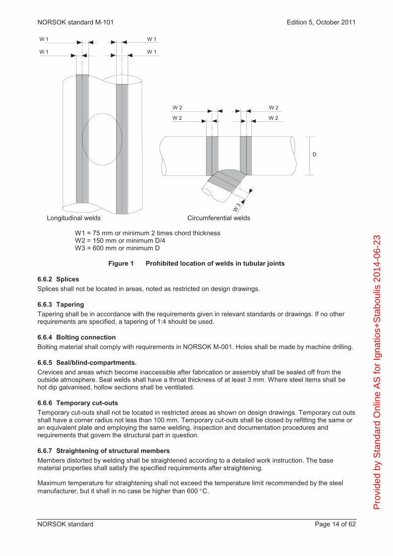
6.6.1 General In tubular joints, circumferential and longitudinal weld joints should not be placed in the shaded areas shown in Figure 1, unless otherwise shown on design drawings.
Pro
vide
d by
Sta
ndar
d O
nlin
e A
S fo
r Ig
natio
s+S
tabo
ulis
201
4-06
-23
NORSOK standard M-101 Edition 5, October 2011
NORSOK standard Page 14 of 62
W 1
W 1
W 1
W 1
W 2
W3
D
W 2
W 2
W 2
Longitudinal welds Circumferential welds
W1 = 75 mm or minimum 2 times chord thickness W2 = 150 mm or minimum D/4 W3 = 600 mm or minimum D
Figure 1 Prohibited location of welds in tubular joints
6.6.2 Splices Splices shall not be located in areas, noted as restricted on design drawings.
6.6.3 Tapering Tapering shall be in accordance with the requirements given in relevant standards or drawings. If no other requirements are specified, a tapering of 1:4 should be used.
6.6.4 Bolting connection Bolting material shall comply with requirements in NORSOK M-001. Holes shall be made by machine drilling.
6.6.5 Seal/blind-compartments. Crevices and areas which become inaccessible after fabrication or assembly shall be sealed off from the outside atmosphere. Seal welds shall have a throat thickness of at least 3 mm. Where steel items shall be hot dip galvanised, hollow sections shall be ventilated.
6.6.6 Temporary cut-outs Temporary cut-outs shall not be located in restricted areas as shown on design drawings. Temporary cut outs shall have a corner radius not less than 100 mm. Temporary cut-outs shall be closed by refitting the same or an equivalent plate and employing the same welding, inspection and documentation procedures and requirements that govern the structural part in question.
6.6.7 Straightening of structural members Members distorted by welding shall be straightened according to a detailed work instruction. The base material properties shall satisfy the specified requirements after straightening. Maximum temperature for straightening shall not exceed the temperature limit recommended by the steel manufacturer, but it shall in no case be higher than 600 C.
Pro
vide
d by
Sta
ndar
d O
nlin
e A
S fo
r Ig
natio
s+S
tabo
ulis
201
4-06
-23

NORSOK standard M-101 Edition 5, October 2011
NORSOK standard Page 15 of 62
6.6.8 Doubler plates All temporary attachments which shall be flame cut or welded under water shall be attached to the structure by using doubler plates. All attachments in the splash zone shall be attached to the structure by using doubler plates.
6.7 Preparation for coatings Edges of plates and structural shapes which are intended to be coated shall be rounded to approximately 2 mm radius, unless otherwise indicated on fabrication drawings.
6.8 Preparation and fit-up of weld bevels Permanent backing strips are not accepted, unless shown in fabrication drawings. Buttering shall be welded in accordance with applicable WPS. The WPS shall be supported by a butt weld WPQR. The responsible NDT-coordinator/personnel shall be notified every time buttering is performed in any groove. Maximum buttering is limited to t/2, maximum 20 mm in the joint. Tack welds shall normally have a length of minimum 100 mm. For material thickness less or equal to 25 mm, tack length may be minimum 4 x plate thickness.
6.9 Welding processes The welding processes listed in ISO 15614-1 are acceptable.
6.10 Welding consumables The manufacturers shall ensure that welding consumables applied for joints where steel quality level I, II and III are required, meet the requirements for mechanical properties as specified for the welding procedure qualification, in both as welded and (where applicable) PWHT condition. This may be achieved through (alternatively): batch testing including chemical analysis and mechanical properties, see Annex D; an established and reliable system of batch certification against accepted supplier data sheets, see Annex
C; for steels with SMYS > 500 MPa, Annex D is mandatory.
Except for solid wires such consumables shall be classified by the supplier as extra low hydrogen, i.e. HDM 5 ml/100 g weld metal. For self shielded flux cored wire HDM 8 ml/100 g may be accepted, provided preheating temperature and post weld holding temperature and time is assessed to avoid hydrogen cracking. Hydrogen testing shall be according to ISO 3690 or equivalent. For all steels with SMYS > 500 MPa special precautions shall be taken to verify that selected consumables comply with hydrogen requirements. Stricter requirements than given above may be relevant. Prequalification with mock-up structures shall apply if there is a risk for high restraint in welding or erection. Consumables for joints in steel quality level III (with SMYS < 355 MPa) and IV and for joining stainless to carbon steel shall be selected with due consideration of base material properties, thickness and weldability, to ensure sufficient weld strength, toughness and homogenity. Such consumables shall be delivered with EN 10204, type 2.2, certificate, as a minimum. All welding consumables shall be individually marked. When certification according to Annex C is used, welding consumables (except welding fluxes) shall be supplied with an inspection certificate type 3.1 in accordance with EN 10204, including a statement of compliance with the welding consumable data sheet and the chemical composition of the weld deposit (elements of the data sheet). Welding fluxes shall be supplied with a test report (EN 10204, type 2.2), declaring conformity with the approved product type.
6.11 Preheat and interpass temperature Preheating above 50 °C should be achieved by electric heating elements. Cutting torches are not allowed for preheating. P
rovi
ded
by S
tand
ard
Onl
ine
AS
for
Igna
tios+
Sta
boul
is 2
014-
06-2
3

NORSOK standard M-101 Edition 5, October 2011
NORSOK standard Page 16 of 62
The minimum interpass temperature shall not drop below the minimum required preheat temperature. If not otherwise stated in the WPS, and qualified by the WPQR, the maximum interpass temperature shall not exceed 250 C measured at the edge of the groove. For C- and C/Mn-steels, a maximum interpass temperature of 250 C may be used, even if a lower temperature was recorded on the WPQR. The preheat temperatures used during repair welding should be minimum 50 C higher than the preheat used for the original weld. NOTE Production welding of high strength steels with SMYS > 500 MPa is normally more sensitive to hydrogen cracking than experienced during welding for qualification. Special precautions, including preheating temperature, minimum holding temperature and extended post weld holding temperature for 24 h or more, shall be taken into consideration.
6.12 Production welding
6.12.1 General Welding shall be carried out in accordance with the WPS and applicable drawings. The applicable WPS shall be given directly to the welder and be available at the site of welding at all times A collection of WPS`s on walls or boards are only for general information and not accepted used for welding. Butt welds in joints where steel quality level I and level II for all strength levels, or steel quality level III for SMYS > 400 MPa are required shall, whenever possible, be welded from both sides. If any welding is conducted after PWHT, the PWHT shall be repeated. For joints in inspection category A, the ”straight” edges of K- and half V-butt weld grooves shall have a groove angle of at least 10º, unless it is documented that possible defects can be detected by the UT technique used. For K-grooves, the 10º should be machined from the root to each plate surface. Any occurrence of cracking during production welding shall be investigated. Welding should be suspended until the cause of cracks and defects has been identified and measures taken to prevent their reoccurrence. Cracks or other persistent weld defects may lead to revision and requalification of the WPS.
6.12.2 Attachments Temporary attachments as lifting lugs, lugs for scaffolding and assembly, supports for cables, equipment, ladders or other fabrication and erection aids should be removed. If indicated on design drawings that removal (full or partial) is not required, the temporary attachments may be left as is, or removed only partially. All welding of attachments shall comply with the requirements for the structure to which they are attached. Temporary attachments shall be cut minimum 3 mm from the base metal and ground. The ground area shall be visually examined and magnetic particle/penetrant tested (as relevant) in accordance with the inspection category in question.
6.12.3 Stainless steel components Permanent or temporary structural elements, attachments or penetration sleeves in stainless steel materials may be selected for various purposes. Requirements for welding and inspection of stainless outfitting structures shall follow similar classification principles as for other structural steel elements, see annex G. All welding and inspection of welds to carbon steel structures shall as a minimum comply with the requirements for the structure to which they are attached. Welding consumables shall be selected in accordance with G.4.
6.13 Post weld heat treatment (PWHT) PWHT shall be required for structural welds in steel quality level I or level II, or quality level III with yield strength Re > 400 MPa, when the nominal thickness as defined in ISO 15614-1, exceeds 50 mm, unless adequate fracture toughness can be documented in the as welded conditions. For restrained joints of complicated design, PWHT may be required for smaller thicknesses, independent of steel quality level. PWHT shall be carried out in accordance with a procedure which shall include P
rovi
ded
by S
tand
ard
Onl
ine
AS
for
Igna
tios+
Sta
boul
is 2
014-
06-2
3

NORSOK standard M-101 Edition 5, October 2011
NORSOK standard Page 17 of 62
heating rate, cooling rate, soaking temperature and time, heating facilities, insulation, control devices, recording equipment, configuration of structure to be PWHT or details if local PWHT shall be carried out, number and location of thermocouples to be used during PWHT.
The holding time and temperature shall be as recommended by the steel manufacturer. The temperature difference between different parts of the structure during soaking time shall not exceed 30 C within the heated area. Double sided heating shall be used as far as possible. The temperatures shall be continuously and automatically recorded on a chart.
6.14 Grinding When grinding is specified on design drawings or is instructed as a corrective action, the grinding shall be performed according to a detailed procedure. Grinding tools, direction, surface roughness and final profile shall be specified. Reference samples for typical joints and sections may be prepared and used for acceptance of treated welds. Typical examples for requirements for grinding of joints are given in A.1.
6.15 Peening Weld improvement by peening shall be performed in accordance with detailed procedures. Normally pregrinding of a groove will be required to assure correct location of peening area. Tools for grinding and peening, surface roughness and profile of grinding as well as peening shall be specified. Tools for check and measurements shall be described and shall be available during operations. Documentation of correct performance shall include macrophotography. Typical examples of requirements for peening of joints are given in A.2.
7 Production tests Production tests shall be selected on weldments in critical regions to verify that the specified requirements have been meet. Minimum one test coupon is required from each applied welding process. Test coupons shall be welded in a manner which realistically simulates the actual production welding, normally as extension of the production weld, and meet the requirements for welding procedure approval tests. CTOD testing is not required for production testing. If a production test fails, the reason for the failure shall be determined and remedial action implemented.
8 Fabrication tolerances Fabrication tolerances shall be in accordance with Annex E, unless otherwise specified on drawings.
9 Non-destructive testing (NDT)
9.1 General The inspection category shall be decided by the designer in accordance with NORSOK N-004, and shall be specified on the design drawings. Final inspection and NDT of structural steel welds shall not be carried out before 48 h after completion except where PWHT is required. The time delay may be reduced to 24 h for steel grades with SMYS of 355 MPa or lower, and for steel grades with SMYS of 420 MPa or lower for plate thicknesses below 40 mm, provided delayed cracking have not been observed for the materials and/or welding consumables in question. P
rovi
ded
by S
tand
ard
Onl
ine
AS
for
Igna
tios+
Sta
boul
is 2
014-
06-2
3

NORSOK standard M-101 Edition 5, October 2011
NORSOK standard Page 18 of 62
When PWHT is performed, the final NDT shall be carried out when all heat treatment have been completed. Prior to fabrication start-up, contractor shall implement a system for recording of weld defect rates. The defect rates shall be recorded on a weekly basis for VT, MT, PT, UT and RT from each production area (geographically split in production areas at the same yard) and shall be reported together with the accumulated defect rate. The defect rate statistics shall be used as a tool in weld quality control. Causes for defects shall immediately be investigated and corrective actions shall be taken to prevent further occurrence. Cracks detected with any NDT method shall require documented investigation/action by the responsible welding engineer. The defects shall be reported with reference to the numbering system according with ISO 6520-1. At a weekly high defect rate or at repeated occurrence of planar defects, two trigger levels apply for extended NDT for welds in inspection category B, C and D. Two steps of actions apply within trigger level 2. Trigger level 1 If a defect rate for any method exceed 10 % for a single week the extent shall be increased to 100 % for all welds in question. Trigger level 2 If a defect rate for any method of 5 % to 10 % for a single week is observed the following two steps of extended NDT shall apply: Step 1. A defect rate for any NDT method exceeding 5 % (1 % for MT) for a single week require doubling of the extent of NDT according to the inspection category. Spot extent shall be increased to 20 %. Step 2. If the defect rate for the weld length where the extended NDT is taken in accordance with Step 1 above exceed 5 %, the extent shall be increased to 100 % for all welds in question
The increased NDT extent shall cover welds of the same inspection categories, welded in the same period of time by the specific welder(s) and WPS when the high defect rate was produced, to assure that the weld quality is maintained also with the lower extent of NDT. Unless the causes for defects found leads to immediate and documented preventive actions, the higher level of extent of NDT shall be maintained until the weekly defect rate is well below 5 %. Generally, if the defect rate approaches 10 % during any stage in production welding, further welding should be held until investigations are completed and corrective actions implemented. A low defect rate may be used as basis for a reduction in the extent of NDT for inspection categories B, C and D, provided that a correct defect rate identification is prepared for each weld method, each NDT method and each production area, see Table 3, table footnote b.
welds)of parts testedof(Length %) 100length x (Defect :as defined is ratedefect The
NOTE “Tested part of welds” means the part that is tested with the same NDT method. Defect rate shall be based on at least 5 welds or 1 m tested weld length. NDT after repair shall not be included when calculating the defect rate.
9.2 Qualification of non-destructive testing (NDT) operators Personnel responsible for all NDT activities shall be qualified according to EN 473, Level 3 (or ISO 9712) or equivalent 3rd party certification scheme. NDT personnel performing visual inspection of welded joints shall be qualified in accordance with EN 473, VT level 2 or equivalent 3rd party certification scheme. NS 477 latest revision may be used. The NDT operator shall be qualified according to EN 473, level 2 or equivalent 3rd party certification scheme. P
rovi
ded
by S
tand
ard
Onl
ine
AS
for
Igna
tios+
Sta
boul
is 2
014-
06-2
3

NORSOK standard M-101 Edition 5, October 2011
NORSOK standard Page 19 of 62
Operators simply producing radiographs and not performing evaluation, do not require level 2, but shall have sufficient training. Ultrasonic operators performing inspection of welds in duplex stainless steel material shall be specially trained and qualified for the purpose according to EN 473 or equivalent 3rd party certification scheme When testing of castings or forgings, the NDT operator shall document experience with forged and cast products.
9.3 Extent of visual examination and non-destructive testing (NDT) The required minimum extent of examination/testing is given in Table 3. Design drawings may show areas of welds where testing is mandatory. Testing performed shall be representative for the weld quality. Partial NDT shall normally be planed for on all shop drawings. Ultrasonic testing to reveal the presence of possible weld metal transverse cracking shall be included for butt welds with thickness more than 25 mm. The testing shall be performed on minimum 5 % of welds in inspection category A and B for SAW (12) and FCAW (131 and 136).
Table 3 Minimum extent (in %) of non-destructive testing for structural welds
Inspection category
Type of connection
Visual examination
Extent of testing %
% RT UT MT A Buttweld
T-connection Fillet/partial
100 100 100
10 - -
100 100
20 c
100 100 100
Ba Buttweld T-connection Fillet/partial
100 100 100
Spot - -
50 b 50 b
10 b c
100 b 100 b
100 b Ca Buttweld
T-connection Fillet/partial
100 100 100
- - -
20 b 20 b
spot c
20 b 20 b
20 b Da All connections 100 - - spot E All connections 100 - - -
Key Spot means 2 % to 5 %. a Increased extent of NDT shall be as defined in relevant Trigger levels in 9.1.
The required level of increased extent shall be maintained until a defect rate below 5 % is re-established and documented.
b The extent may be reduced to 50 % of the specified extent, based on experience and documented
records with similar joints, provided the defect rate (see 9.1) for UT/RT is < 2,0 % and for MT is < 0,2 % during the last 100 m of weld. The last 100 m shall be continuously updated every week. If the defect rate exceeds the limits given above, the normal extent of NDT shall apply again. A possible reduction in the extent of NDT shall be considered separately for each welding method and each production area.
c Applies only for partial penetration welds with a penetration depth greater than 12 mm.
When partial testing is defined for welds in an area, the testing shall be spread such that the most essential members and nodes are included in the inspection, and such that areas of welds most susceptible to weld defects are covered. The specified percentage to be tested in Table 3 refers to the total length of welds in each inspection category. P
rovi
ded
by S
tand
ard
Onl
ine
AS
for
Igna
tios+
Sta
boul
is 2
014-
06-2
3

NORSOK standard M-101 Edition 5, October 2011
NORSOK standard Page 20 of 62
All WPSs used and welds representing all welding personnel involved in the fabrication shall be subject to NDT. During the initial fabrication the extent of UT and MT of inspection category B and C welds shall be intensified, normally to twice the level given in Table 3. This extent shall be maintained for a weld and test length sufficient to conclude that the weld repair percentage is at a reasonable level. The increased initial testing may be accounted for in the overall extent provided the initial testing confirms consistent good workmanship. In addition to what is listed in Table 3, the following shall apply for inspection category A and B: a) one film at each end for longitudinal welds of tubulars (including tubulars for nodes and stubs); b) where radiographic testing is required, intersection welds, and those locations where presence of defects
is deemed to be most harmful, shall be tested; c) ultrasonic and radiographic testing shall not overlap, except when 100 % UT is specified. However,
ambiguous imperfections revealed by UT shall in addition be tested by RT; d) ultrasonic testing is normally not applicable for thicknesses less than 10 mm. For such thicknesses, UT
shall be replaced with RT. In general, RT should be considered if UT is not possible. Radiographic testing is normally not applicable for thicknesses above 40 mm.
9.4 Visual examination and finish of welds The visual examination shall be carried out in accordance with ISO 17637.
9.5 Radiographic testing Radiographic testing shall be carried out in accordance with ISO 17636, Class A. The general film density shall be ≥ 2,0. However, if X-ray are used, the minimum film density may be reduced to 1,5. Suspect planar indications discovered by RT shall be type determined, located and sized by UT.
9.6 Ultrasonic testing Ultrasonic testing of welds in plate and tubular butt welds and double side welded tubular joints shall be performed in accordance with ISO 17640, examination level C. Reference blocks shall be made with thickness and side-drilled holes in accordance with Table 4. DAC reference curves shall be established. The effective test range of a DAC curve shall be determined by the point at which the curve has fallen to 25 % FSH, when it will be necessary to raise the curve using reflectors at increased depth. The reference block shall be from a steel type that is representative for the steel to be inspected. Where ultrasonic testing is to be performed on steel produced by controlled rolling or thermo mechanical treatment, reference blocks shall be produced both perpendicular to, and parallel to, the direction of rolling. The rolling direction shall be clearly identified. The actual refracted angle for each probe measured from the reference block or as measured on the actual object being examined, shall be used when plotting indications. Ultrasonic testing procedures shall be sufficiently detailed to ensure 100 % of the weld body and heat affected zones are examined for longitudinal defects. All indications exceeding -10dB DAC shall be investigated to the extent that they can be evaluated in terms of the acceptance criteria. For butt welds, (C and D) or (E and F) according to ISO 17640 shall be utilised for the detection of transverse imperfections, providing that the surface finish of the weld cap is sufficiently smooth and in accordance with clause 8 of ISO 17640.
Pro
vide
d by
Sta
ndar
d O
nlin
e A
S fo
r Ig
natio
s+S
tabo
ulis
201
4-06
-23

NORSOK standard M-101 Edition 5, October 2011
NORSOK standard Page 21 of 62
Alternatively techniques (X and Y) or (W and Z) according to ISO 17640 can be utilised by placing the probe alongside the weld connection, so that the beam forms a small angle with the centreline. If the surface finish adjacent to the weld is such that testing with an angle probe using techniques (C and D) or (E and F) along the centre line of the weld is judged to be the only reliable method of examination, than the weld cap is to be dressed smooth or ground flush with the parent material in accordance with clause 8 of ISO 17640. Scanning is in all cases to be performed from both sides of the weld and in both directions. The examination record shall include the position, the echo height, length, depth and type of indication.
Table 4 Calibration reference block requirements Thickness of material
to be examined mm
Thickness of block
mm
Diameter of hole
mm
Distance of hole from one surface
mm 10 < t < 50 40 or t 3 +/-0,2 50 < t <100 75 or t t/2 and t/4 100 < t <150 125 or t Additional holes are 150 < t <200 175 or t 3 +/-0,2 allowed and 200 < t <250 225 or t recommended
t > 250 275 or t
9.7 Magnetic particle and penetrant testing Magnetic particle testing shall be carried out in accordance with ISO 17638. Magnetic yokes using alternating current shall be used. Prods are acceptable where the geometry of the welded joint prevents the use of yokes. Permanent magnets are not acceptable. MT shall be performed on both external and internal surface as accessible or as required by the designer. For non-magnetic materials penetrant testing in accordance with ISO 3452-1 should be used.
9.8 Acceptance criteria
9.8.1 General All welds shall comply with the requirements given below, in 9.8.2 to 9.8.5.
9.8.2 Visual examination All welds shall show evidence of good workmanship. The quality shall comply with the requirements of Table 5.
9.8.3 Radiographs The soundness of the welded joint shall comply with the requirements of Table 6.
9.8.4 Ultrasonic testing acceptance criteria The acceptance criteria for welds shall comply with Table 7 unless more stringent requirements are specified by the designer.
9.8.5 Magnetic particle testing Linear indications (i.e. indications with a length/width ratio above 3 and length above 1,5 mm ) are not acceptable. Any linear indications shall be ground and re-examined. Rounded indications shall be evaluated in accordance with the requirements of Table 5. The same acceptance criteria applies for penetrant testing.
9.8.6 All methods All defects shall be repaired according to Clause 10. All indications exceeding acceptance criteria shall be reported, unless more stringent requirements are given. P
rovi
ded
by S
tand
ard
Onl
ine
AS
for
Igna
tios+
Sta
boul
is 2
014-
06-2
3
NORSOK standard M-101 Edition 5, October 2011
NORSOK standard Page 22 of 62
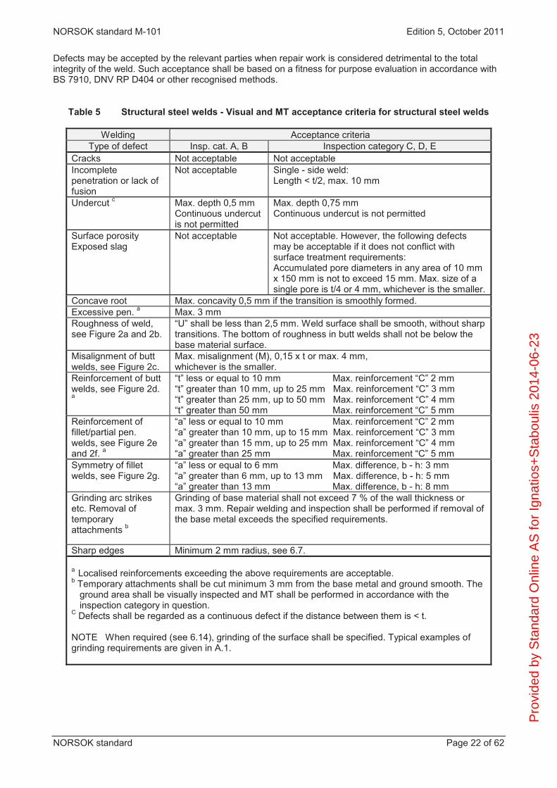
Defects may be accepted by the relevant parties when repair work is considered detrimental to the total integrity of the weld. Such acceptance shall be based on a fitness for purpose evaluation in accordance with BS 7910, DNV RP D404 or other recognised methods.
Table 5 Structural steel welds - Visual and MT acceptance criteria for structural steel welds
Welding Acceptance criteria Type of defect Insp. cat. A, B Inspection category C, D, E
Cracks Not acceptable Not acceptable Incomplete penetration or lack of fusion
Not acceptable Single - side weld: Length < t/2, max. 10 mm
Undercut c Max. depth 0,5 mm Continuous undercut is not permitted
Max. depth 0,75 mm Continuous undercut is not permitted
Surface porosity Exposed slag
Not acceptable
Not acceptable. However, the following defects may be acceptable if it does not conflict with surface treatment requirements: Accumulated pore diameters in any area of 10 mm x 150 mm is not to exceed 15 mm. Max. size of a single pore is t/4 or 4 mm, whichever is the smaller.
Concave root Max. concavity 0,5 mm if the transition is smoothly formed. Excessive pen. a Max. 3 mm Roughness of weld, see Figure 2a and 2b.
“U” shall be less than 2,5 mm. Weld surface shall be smooth, without sharp transitions. The bottom of roughness in butt welds shall not be below the base material surface.
Misalignment of butt welds, see Figure 2c.
Max. misalignment (M), 0,15 x t or max. 4 mm, whichever is the smaller.
Reinforcement of butt welds, see Figure 2d. a
“t” less or equal to 10 mm Max. reinforcement “C” 2 mm “t” greater than 10 mm, up to 25 mm Max. reinforcement “C” 3 mm “t” greater than 25 mm, up to 50 mm Max. reinforcement “C” 4 mm “t” greater than 50 mm Max. reinforcement “C” 5 mm
Reinforcement of fillet/partial pen. welds, see Figure 2e and 2f. a
“a” less or equal to 10 mm Max. reinforcement “C” 2 mm “a” greater than 10 mm, up to 15 mm Max. reinforcement “C” 3 mm “a” greater than 15 mm, up to 25 mm Max. reinforcement “C” 4 mm “a” greater than 25 mm Max. reinforcement “C” 5 mm
Symmetry of fillet welds, see Figure 2g.
“a” less or equal to 6 mm Max. difference, b - h: 3 mm “a” greater than 6 mm, up to 13 mm Max. difference, b - h: 5 mm “a” greater than 13 mm Max. difference, b - h: 8 mm
Grinding arc strikes etc. Removal of temporary attachments b
Grinding of base material shall not exceed 7 % of the wall thickness or max. 3 mm. Repair welding and inspection shall be performed if removal of the base metal exceeds the specified requirements.
Sharp edges Minimum 2 mm radius, see 6.7. a Localised reinforcements exceeding the above requirements are acceptable. b Temporary attachments shall be cut minimum 3 mm from the base metal and ground smooth. The
ground area shall be visually inspected and MT shall be performed in accordance with the inspection category in question.
C Defects shall be regarded as a continuous defect if the distance between them is < t. NOTE When required (see 6.14), grinding of the surface shall be specified. Typical examples of grinding requirements are given in A.1.
Pro
vide
d by
Sta
ndar
d O
nlin
e A
S fo
r Ig
natio
s+S
tabo
ulis
201
4-06
-23
NORSOK standard M-101 Edition 5, October 2011
NORSOK standard Page 23 of 62
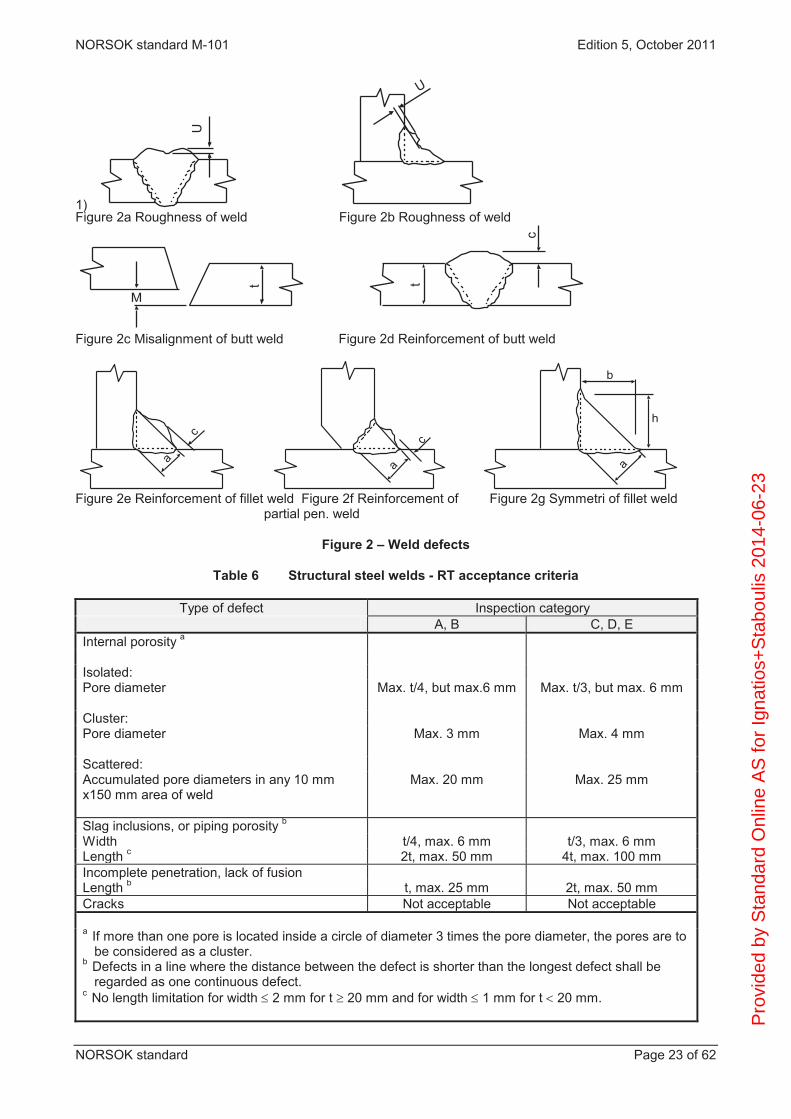
1) U
U
Figure 2a Roughness of weld Figure 2b Roughness of weld
c
t
M
t
Figure 2c Misalignment of butt weld Figure 2d Reinforcement of butt weld
c
ac
a a
b
h
Figure 2e Reinforcement of fillet weld Figure 2f Reinforcement of Figure 2g Symmetri of fillet weld
partial pen. weld
Figure 2 – Weld defects
Table 6 Structural steel welds - RT acceptance criteria
Type of defect Inspection category A, B C, D, E
Internal porosity a Isolated: Pore diameter Max. t/4, but max.6 mm Max. t/3, but max. 6 mm Cluster: Pore diameter Max. 3 mm Max. 4 mm Scattered: Accumulated pore diameters in any 10 mm x150 mm area of weld
Max. 20 mm Max. 25 mm
Slag inclusions, or piping porosity b Width t/4, max. 6 mm t/3, max. 6 mm Length c 2t, max. 50 mm 4t, max. 100 mm Incomplete penetration, lack of fusion Length b t, max. 25 mm 2t, max. 50 mm Cracks Not acceptable Not acceptable a If more than one pore is located inside a circle of diameter 3 times the pore diameter, the pores are to
be considered as a cluster. b Defects in a line where the distance between the defect is shorter than the longest defect shall be
regarded as one continuous defect. c No length limitation for width 2 mm for t 20 mm and for width 1 mm for t 20 mm. P
rovi
ded
by S
tand
ard
Onl
ine
AS
for
Igna
tios+
Sta
boul
is 2
014-
06-2
3

NORSOK standard M-101 Edition 5, October 2011
NORSOK standard Page 24 of 62
Table 7 Structural steel welds - UT acceptance criteria
Description Inspection category A + B
Inspection category C, D, E
NOTE
General If the type of defect can not be ascertained with certainty the defect shall be repaired when the length exceeds 10 mm and the echo height exceeds the reference curve.
1 2 3 4
Cracks Unambiguous cracks are unacceptable regardless of size or amplitude.
Lack of fusion or incomplete penetration
Internal defects : I: The echo height exceeds the reference curve: Max. length t, Max. length 2t, Max. 25 mm Max. 50 mm II: The echo height is between 50 and 100% of the reference curve: Max. length 2t, Max. length 4t, Max. 50 mm Max. 100 mm Surface defects are not acceptable except: For root defects in single sided welds, the max. length for which the echo height exceeds the reference curve shall be: Max. length t, Max. length 2t, Max. 25 mm Max. 50 mm
1 2 3 4 5
Slag inclusions
When echo height exceeds the reference curve: Max. length 2t, Max. length 4t, Max. 50 mm Max. 100 mm
1 2
Porosity Repair is required if porosity may mask for other defects. 1
NOTE 1 Type of defect shall be decided by:
I: Supplementary non-destructive testing. II: The ultrasonic operator's assessment of the defect, using his knowledge of the welding process, signal geometry, defect position etc.
NOTE 2 If elongated defects are situated on line and the distance between them is less than the length of the longest indication, the defects shall be evaluated as one continuous defect.
NOTE 3 Defect length is defined as the distance between points where the echo reach or pass 50 % DAC (for defects larger than the beam). For defects smaller than the beam, the maximum amplitude technique may be used.
NOTE 4 With UT performed from only one side of the weld with only one surface accessible, the acceptable echo heights are reduced from 100 % to 50 % and from 50 % to 20 %, respectively.
NOTE 5 With “internal defects” it is meant defects which are located more than 6 mm from the nearest surface. A defect is classified as a “surface defect” if any part of the defect is located less than 6 mm or t/4, whichever is smaller, from the nearest surface.
10 Repair
10.1 Definitions Weld discontinuities: Irregularities in the body of the weld or on the weld surface classified as either weld imperfection or as weld defect. Weld imperfection: Discontinuities that are within the acceptance criteria defined in Clause 9 and are considered to have no practical limitations on the intended use of the product. Weld imperfections may be left without remedial work. Cosmetic grinding may be performed at the discretion of the fabricator. Weld defect: Discontinuity with a size and/or density that exceeds the acceptance criteria defined in Clause 9.
Pro
vide
d by
Sta
ndar
d O
nlin
e A
S fo
r Ig
natio
s+S
tabo
ulis
201
4-06
-23
NORSOK standard M-101 Edition 5, October 2011
NORSOK standard Page 25 of 62
10.2 Correction of welds containing defects All repairs shall be carried out in accordance with established procedures. Welds containing cracks shall not be repaired, until the reason for the cracking has been determined. If necessary, the defective part of the weld shall be cut out for further examination. Crater cracks may be repaired by grinding followed by NDT and subsequent repair welding according to an accepted repair welding procedure. Other defects shall be corrected by grinding, repair welding or re-welding. When weld defects are removed by grinding only, the final weld surface and the transition to the base material shall be smooth. Removal of defects shall be verified by local visual inspection, aided by applicable NDT methods. If applicable, the remaining thickness in the ground area shall be measured. Repair welding is required if the remaining thickness is less than that specified.
10.3 Repair by welding
10.3.1 Repair and re-repair welding Before repair welding, the defect shall be completely removed. The excavated area shall have smooth transitions to the metal surface and allow good access for both NDT after excavation and subsequent repair welding. After excavation, complete removal of the defect shall be confirmed by MT or PT. PWHT shall be performed after repair if specified for the original weld. The excavated groove shall be minimum 50 mm long, measured at defect depth even if the defect itself is smaller. Defects spaced less than 100 mm shall be repaired as one continuous defect. After repair welding the complete weld (i.e. the repaired area plus at least 100 mm on each side) shall be subjected at least to the same NDT as specified for the original weld. Repair welding may only be carried out twice in the same area.
10.3.2 Re-welding Re-welding shall be performed in accordance with the procedures and WPS utilised for the original weld, and includes complete removal of the original weld and HAZ.
10.4 Repair welding procedure Repair and re-re-repair welding may be performed using the same WPS as for the original weld, or a separately qualified procedure. For repairs using a different process, and/or consumable, a separate WPS shall be qualified if required by 5.2. Mechanical testing may be limited to HAZ Charpy V-notch testing in the original weld, provided the process/consumable is backed up by other welding procedure qualification records (WPQRs).
10.5 Correction of distortion Improperly fitted parts should be cut apart and re-welded in accordance with the applicable qualified WPS. Parts distorted by welding, beyond the tolerances, should be straightened in accordance with the requirement in Clause 6.
Pro
vide
d by
Sta
ndar
d O
nlin
e A
S fo
r Ig
natio
s+S
tabo
ulis
201
4-06
-23

NORSOK standard M-101 Edition 5, October 2011
NORSOK standard Page 26 of 62
Annex A (Informative)
Details for high fatigue utilisation
A.1 Typical grinding details
TYP. TUBULAR JOINT GRINDING DETAIL
TYPICAL GRINDING DETAILSFOR HIGH FATIGUE UTILISATION
T4= 2mm or 0,05 x T3 max.(wichever is less)
Removesharp edges
OUTSIDE
BRACE WALL
T4
T3
T2 = 2mm or 0,05 x T1 max.(wichever is less)
T1
Removesharp edges
Weld rad.
Rotary burr grinder
chord wall
Remove overlap flushwith plate surface
Blend out to remove edge on undercut
Maximum depth below platesurface for blend is not to exceed1,5mm
Grinding direct ion
TYP. BUTT WELD JOINT GRINDING DETAIL
NOTE 1 For removal of undercuts the toe of the weld should be blended in a smooth transition and extended below the plate
surface in order to remove the toe defects. NOTE 2 Grinding should extend below plate surface to a minimum of 0,5 mm below the bottom of any visible undercut and ensuring
that no exposed defects remain, using a rotary burr grinder. Grinding marks should run at right angels to weld axis and under no circumstances parallel to it.
NOTE 3 Minimum radii of weld profiles after blending should not be less than 10 mm. NOTE 4 Upon completion of blending of toe the whole of the ground surface shall be inspected with 100% visual examination and
100 % MT. NOTE 5 Ground surface shall be free of any cracks or crack like indications, and there shall be no evidence of undercut or overlap.
Pro
vide
d by
Sta
ndar
d O
nlin
e A
S fo
r Ig
natio
s+S
tabo
ulis
201
4-06
-23
NORSOK standard M-101 Edition 5, October 2011
NORSOK standard Page 27 of 62
A.2 Typical peening details
A.2.1 General Peening of local area as weld toe or weld trasition is an acceptable method to improve fatigue life of structures. Peening is applied together with grinding where grinding serves the purposes to remove stress risers such as surface defects and to define a steering grove for the tool in the area to be peened. Both grinding and peening require skills and preparations not normally available in fabrication yards. Due to the dependancy of correct performance specific precautions shall be taken when peening is planned for.
A.2.2 Requirements for application When peening is planned for the following preparations are required: nomination of responsible engineer for preparations, performance and documentation; a complete responsibility and personnel matrix; statement on expected or required improvements; detailed work instructions; documentation on operators experience, skill or training; selection of peening methods to be applied; detailed mark up drawings showing all areas of application; detailed stepwise procedure for the work, including
grinding details as tools, radius, depth and direction, tools to be used for peening, method, intensity and extent of peening, quality control measures, documentation of performance and results.
verification of performance, e.g. experiments, tests or other relevant information; as built record index for the final design, fabrication and installation resume.
As preparation for peening the surface shall be dressed in a way that makes lack of coverage detectable, preferably by stone grinding. Applicable tool for grinding is normally a rotary burr or stone of 6 mm to 8 mm diameter when a single tool hammer is used and 10 mm to 12 mm when a needle hammer is used. The depth of the groove is approximately 0,5 mm below the original surface. All surface defects shall be removed by grinding prior to peening. Applicable tool for peening is normally pneumatic hammers. A needle hammer is normally used when a wider area shall be covered. For local toe peening a single tool hammer is recommended. Correct tool is essential to maintain correct peening in compliance with requirements. Special tools with adjusted curvature shall be prepared in accordance with weld geometry. Needle peening shall be applied with a coverage of minimum 200 %. Single hammer peening shall result in a fully covered hammered groove where the surface is smooth with uniform indentation. All traces from previous grinding shall be completely removed. Devices for quality control and documentation shall be thoroughly selected. Groove depth measuring tools and macro photo is normally applied. Reference specimens shall be prepared for comparison between ground and final peened surfaces.
Pro
vide
d by
Sta
ndar
d O
nlin
e A
S fo
r Ig
natio
s+S
tabo
ulis
201
4-06
-23

NORSOK standard M-101 Edition 5, October 2011
NORSOK standard Page 28 of 62
Annex B (Informative)
Correlation between steel quality level, MDS number and steel grade/designations
Steel quality level
MDS No.
Rev. no.
Standard Product type Steel grade (see product
standard)
ISO/TR 15608
Y20 5 Plates S355G10+N/G10+M
1.2/2.1/3.1
Y21 5 Rolled sections S355G12+N/G12+M
1.2/2.1
Y22 5 Seamless tubulars S355G15+Q/G15+N
1.2/2.1/3.1
Y30 5 Plates S420G2+Q/G2+M 1.2/2.1/3.1 Y31 5 Rolled sections S420G4+M 2.1 Y32 5 Seamless tubulars S420G6+Q 3.1 I Y40 5 EN 10225 Plates S460G2+Q/G2+M 1.2/3.1 Y41 5 Rolled sections S460G4+M 2/2.1/3.1 Y42 5 Seamless tubulars S460G6+Q 2.1./2.2 Y50 5 Plates S500G2+Q/G2+M
a 2.2/3.1
Y51 5 Rolled sections S500G4+M a 2.2/3.1 Y52 5 Seamless tubulars S500G6+Q a 2.2/3.1 Y25 5 Plates S355G9+N/G9+M 1.2/2.1/3.1 Y26 5 Rolled sections S355G11+N/G11
+M 1.2/2.1/3.1
Y27 4 Seamless tubulars S355G14+Q/G14+N
1.2/2.1/3.1
Y28 3 Welded tubulars S355G13+N 1.2 Y35 4 Plates S420G1+Q/G1+M 2.1/3.1 Y36 5 Rolled sections S420G3+M 2.1 Y37 5 Seamless tubulars S420G6+Q 3.1 Y45 5 Plates S460G1+Q/G1+M 2.2/3.1 II Y46 5 EN 10225 Rolled sections S460G3+M 2.2 Y47 5 Seamless tubulars S460G6+Q 3.1 Y55 5 Plates S500G1+Q/G1+M
a 3.1
Y56 5 Rolled sections S500G3+M a 2.2 Y57 5 Seamless tubulars S500G6+Q a 3.1 Y05 3 EN 10025-(all parts) Plates S355J2
S355K2 1.2/2.1
EN 10025-(all parts) Plates and sections S355J2 S355K2
1.2/2.1
Y06 3 EN 10225 Hot finished seamless tubulars
S355G1+N 1.2
III Y07 3 EN 10210-(all parts) Hot finished tubulars S355NH/S355K2H
2.1
Y08 3 EN 10219-(all parts) Cold formed tubulars S355MLH 2.1 Y15 3 EN 10025-(all parts) Plates and sections S420ML 2.1 Y16 3 EN 10219-(all parts) Cold formed tubulars S420MLH 2.1
Y01
5
EN 10025-(all parts) EN 10210-(all parts) EN 10219-(all parts)
Plates and sections Hot finished tubulars Cold formed tubulars
S235JR S235JRH S235JRH
1.1 P
rovi
ded
by S
tand
ard
Onl
ine
AS
for
Igna
tios+
Sta
boul
is 2
014-
06-2
3
NORSOK standard M-101 Edition 5, October 2011
NORSOK standard Page 29 of 62
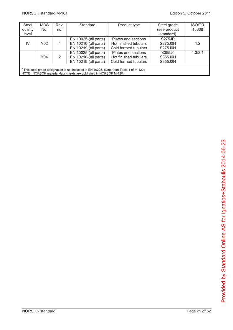
Steel quality level
MDS No.
Rev. no.
Standard Product type Steel grade (see product
standard)
ISO/TR 15608
IV
Y02
4
EN 10025-(all parts) EN 10210-(all parts) EN 10219-(all parts)
Plates and sections Hot finished tubulars Cold formed tubulars
S275JR S275J0H S275J0H
1.2
Y04
2
EN 10025-(all parts) EN 10210-(all parts) EN 10219-(all parts)
Plates and sections Hot finished tubulars Cold formed tubulars
S355J0 S355J0H S355J2H
1.3/2.1
a This steel grade designation is not included in EN 10225. (Note from Table 1 of M-120) NOTE NORSOK material data sheets are published in NORSOK M-120.
Pro
vide
d by
Sta
ndar
d O
nlin
e A
S fo
r Ig
natio
s+S
tabo
ulis
201
4-06
-23

NORSOK standard M-101 Edition 5, October 2011
NORSOK standard Page 30 of 62
Annex C (Normative)
Qualification of welding consumables by data sheets
C.1 General The purpose of certification is to verify that each batch of consumables has a chemical composition within limits as specified by the supplier in conformance with a recognised classification standard. By controlled and certified chemistry the supplier also confirms that mechanical properties of the weld metal fulfil the minimum requirements specified for the product. For this specification a batch (or lot) is defined as the volume of product identified by the supplier under one unique batch/lot number, manufactured in one continuous run from batch controlled raw materials. Each individual consumable (brand name and dimension) shall be certified per batch, except for solid wire (gas tungsten arc welding, gas metal arc welding, SAW), originating from the same heat, where one diameter may represent all.
C.2 Data sheet Each welding consumable or combination of consumables shall have a unique data sheet, issued as a controlled document within the suppliers quality system. The purchaser shall base his selection, ordering and receiving of consumables upon reviewed and accepted data sheets. The data sheet shall give guaranteed limits and/or minimum values for composition and mechanical properties, determined under defined reference conditions. If the consumable shall be used for welds in PWHT condition, then the properties shall also be documented in PWHT condition in addition to the as-welded condition. Specifically this shall include, as applicable: chemical analysis limits for solid wires and metal powders. For information also typical weld metal
analysis, using a relevant shielding gas or flux; chemical analysis limits of weld metal from coated electrodes and cored wires, deposited according to ISO
6847. For information also specified limits for S, P and N in the core wire or strip; The analysis shall include limits for all elements specified in the relevant classification standard and/or intentionally added and for residual elements known to influence weld metal quality. Minimum: C, Si, Mn, S, P, Cu, Ni, Cr, Mo, V, Nb. For SAW fluxes the analysis shall be given as ranges for all main ingredient and flux basicity as follows: mechanical properties (range or/and guaranteed minimum) of the weld, deposited and tested according to
ISO 15792-1 and including tensile strength, yield strength elongation, notch toughness Charpy-V at -40 ºC. For information also typical properties of a relevant butt weld should be added;
diffusible hydrogen content HDM maximum, including any information on drying, restricted welding parameters etc. required to ensure this value in practice;
when relevant for the product, basic information about CTOD properties, to be supported by separate test reports as required and agreed.
Data sheets shall also contain product classification according to recognised standards, relevant approvals and information on packing, storage etc. as required for correct application and use of the product.
C.3 Certificate Every batch of consumables shall be supplied with an inspection certificate 3.1.B, containing as a minimum the specific tested chemical composition of the wire or weld metal, as applicable. The chemical elements P
rovi
ded
by S
tand
ard
Onl
ine
AS
for
Igna
tios+
Sta
boul
is 2
014-
06-2
3
NORSOK standard M-101 Edition 5, October 2011
NORSOK standard Page 31 of 62
shall conform to those of the data sheets, with a statement “below specified maximum” acceptable for residual elements. The supplier may optionally add information about mechanical properties, based on specific or non-specific type of control, see EN 10204. Other tests may also be agreed between supplier and purchaser. Certificates shall be actively used by the purchaser to control received consumables against the accepted data sheet. Full conformance of chemical composition shall be required to release each batch for fabrication welding.
Pro
vide
d by
Sta
ndar
d O
nlin
e A
S fo
r Ig
natio
s+S
tabo
ulis
201
4-06
-23

NORSOK standard M-101 Edition 5, October 2011
NORSOK standard Page 32 of 62
Annex D (Normative)
Welding consumable documented by batch testing
D.1 General The purpose of the batch testing is to verify that the consumables remains nominally equivalent to that used for welding procedure qualification, with respect to chemistry and mechanical properties. For this specification a batch (or lot) is defined as the volume of product identified by the supplier under one unique batch/lot number, manufactured in one continuous run from batch controlled raw materials. Each individual product (brand name and dimensions) shall be tested once per batch, except for solid wire originating from the same heat, where one diameter may represent all. SAW fluxes do not require individual testing, while SAW wires shall be tested in combination with a selected nominal batch of flux.
D.2 Chemical analysis For solid wires and metal powders the analysis shall represent the product itself. For coated electrodes and cored wires the analysis shall represent the weld metal, deposited according to ISO 6847. The analysis shall include all elements specified in the relevant classification standard and /or intentionally added, the main impurities S, P and N.
D.3 Mechanical properties Unless otherwise specified the properties shall represent all weld metal, deposited and tested according to ISO 15792-1. Properties tested shall include tensile strength, yield strength and elongation, impact strength Charpy-V at temperatures -40 °C, or as specified by purchaser.
The need for other types of tests shall be evaluated for the application in question, e.g.: mechanical properties based on a defined butt weld rather than all weld metal test; mechanical properties in the PWHT condition; CTOD testing; testing of hydrogen level.
D.4 Documentation Batch tests shall be documented by an inspection certificate in accordance with EN 10204, 3.1B, with reference to a recognised product classification standard and containing all specified test results.
Pro
vide
d by
Sta
ndar
d O
nlin
e A
S fo
r Ig
natio
s+S
tabo
ulis
201
4-06
-23

NORSOK standard M-101 Edition 5, October 2011
NORSOK standard Page 33 of 62
Annex E (Normative)
Fabrication tolerances
E.1 Scope and objectives This annex defines the maximum allowable dimensional tolerances for offshore steel items and structures. The designer may, however, specify stricter tolerances and additional tolerances. These will, in case take presedence over this annex. NOTE It should be observed that the requirement to fabrication tolerances in this annex may be more strict than the manufacturing tolerances for steel products according to NORSOK M-120. The intention of this annex is to give dimensional tolerances which will ascertain that the calculated strength and fatigue resistance is present in the structures, items and structures can be assembled without dimensional rework, all parts of the structures are suitable for their intended use, the structures are trustworthy relative to measurements given on the structural drawings, the relevant components tolerances are achieved and maintained after the components final incorporation
in the completed structure(s).
E.2 Codes, standards and specifications Reference standards for this annex are ISO 8062:1994 and EN 1090-1:2009.
E.3 Definitions Terminology used in conjunction with this annex: AFC drawing engineering drawings formally approved for construction centreline real or imaginary line that is equidistant from the surface or sides of the (measured) object deflection load imposed curves, bends, angles or irregularities from an unloaded structure NOTE Opposed to straightness deviation. flatness vertical offset at any point from a plane parallel with the surveyed object grid system design reference system for all parts, components and elements of a completed structure NOTE The grid system defines the 3D position of any item within a completed structure.
The grid system is normally denoted in one of the following manners: x, y and z coordinates; north, east and height coordinates; longitudinal, transversal and elevation coordinates.
The grid system defines the design origo (location and elevation datum) for a structure.
position deviation aspecified point's actual position relative to it's nominal position NOTE Measured value minus nominal value equals deviation.
Pro
vide
d by
Sta
ndar
d O
nlin
e A
S fo
r Ig
natio
s+S
tabo
ulis
201
4-06
-23

NORSOK standard M-101 Edition 5, October 2011
NORSOK standard Page 34 of 62
reference lines marked lines on construction parts and assemblies which are parallel to, and in determined distances from grid lines straightness deviation curves, bends, angles or irregularities from a straight generator NOTE Straightness deviation is regarded to be fabrication imposed irregularities and not caused by elastic deformation. survey reference system reference system constituting of fixed and coordinate determined points, from where surveys can be performed, and where the location and elevation of the fixed points are identifiable relative to the grid system work point marked or imaginary point on a member or structure from which dimensions shall be related
E.4 General requirements
E.4.1 Implementation policy of requirements The tolerances given in this annex shall be applied for completed structures. For single elements to be parts of complex structures, specification of detailed and more stringent tolerances for each fabrication and erection sequence may be necessary in order to meet the requirements of this annex in the completed structure. Such tolerances shall be presented in the plan/scope of work for fabrication. Specification of detailed and more stringent tolerances for intermediate and final interfaces may also be necessary in order to meet the requirements of this annex in the completed structure. The allowable tolerances given for individual members shall not cumulate to give unacceptable deviation for the finished section or complete structure. If tolerances given for individual sections and components are conflicting, those tolerances representing the stricter values shall be governing. If no appropriate tolerance is stated in this NORSOK standard, the tolerance requirements shall be agreed. All tolerance requirements are based on nominal values on unloaded structure.
E.4.2 Procedures and documents The following procedures and documents shall be prepared: a) plan for fabrication and erection including methods, techniques and dimensional control to assure that all
structures can be fabricated and assembled to dimensions within the specified tolerances. The plan shall assure that all allowable tolerances for individual elements are not cumulative to the extent of exceeding the allowable tolerance for the complete structure;
b) dimensional inspection procedures relevant for the structures and any additional specifications needed
to those included in this NORSOK standard, subject drawings or other regulations/guidelines for the structural fabrication;
c) the following documents shall be prepared prior to start of fabrication:
1) plan for dimensional assurance/inspection; 2) dimensional inspection procedures.
d) during fabrication and erection deviations outside the specified tolerances shall be identified and
informed of in advance of the formal handling of deviations. The detailed dimensional deviation reports shall be available at all stages in fabrication, and shall be submitted on request;
e) final documentation shall be prepared in correspondence with the requirements for as built
documentation and fabrication record.
Pro
vide
d by
Sta
ndar
d O
nlin
e A
S fo
r Ig
natio
s+S
tabo
ulis
201
4-06
-23

NORSOK standard M-101 Edition 5, October 2011
NORSOK standard Page 35 of 62
E.4.3 Qualification of inspectors Personnel responsible for dimensional control activities shall have a minimum background of at least 5 years relevant experience in industrial surveying. Personnel monitoring dimensions and tolerances shall have relevant training in use and understanding of instruments, and subsequent calculations, enabling them to perform all necessary controls of own work performance.
E.4.4 Instrument reliability All instruments used shall be in accurate permanent adjustment, have current valid control certificates and be subject to a programme of periodic checking.
E.4.5 Reference temperature Reference temperature for survey activities should be +20 ºC. The field work temperature shall as a minimum be noted on all dimensional reports, when this is necessary for future use of the report and the component surveyed. For components to be assembled, built under significantly different temperature conditions, dimensions shall be computed to the reference temperature and this shall be annotated on any subsequently produced document or report.
E.4.6 Control methods
E.4.6.1 Reference system
Prior to fabrication a survey reference system related to the grid system, shall be established. The survey reference system shall use the same numerical values, and the same orientation directions of the system axis as the grid system. The following apply: the system's north axis shall be positive toward platform north (or bow, if ship); the system's east axis shall be positive toward east (or starboard, if ship); the system's elevation shall be positive upward; the numerical value should be the same for all disciplines and packages; for special structures such as jackets being built laying down, the reference system shall be adjusted to
this fabrication situation, but the final as built survey shall be related to the platform grid system. The survey reference system should be established within the following tolerances: Sections/complete structures: 3 mm Stricter survey reference system tolerances shall be used on components where the requirements of the final product are more stringent than the above tolerance. For components where the tolerance of the product are less than 2 mm, the proposed survey methods shall be described. At all stages during fabrication and erection, the Contractor shall ensure that the survey reference system and the fabricated item are shall be in correct position relative to each other. Permanent survey stations shall be properly constructed and be protected from disturbance. The permanent survey stations shall be re-checked periodically, or whenever additional permanent survey stations are established. All additional or re-checked surveys shall be properly documented.
Pro
vide
d by
Sta
ndar
d O
nlin
e A
S fo
r Ig
natio
s+S
tabo
ulis
201
4-06
-23
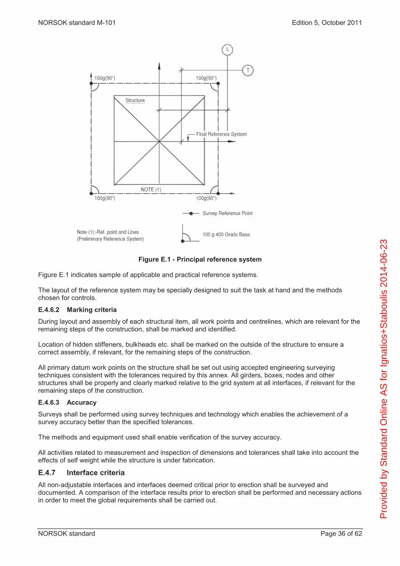
NORSOK standard M-101 Edition 5, October 2011
NORSOK standard Page 36 of 62
Figure E.1 - Principal reference system Figure E.1 indicates sample of applicable and practical reference systems. The layout of the reference system may be specially designed to suit the task at hand and the methods chosen for controls.
E.4.6.2 Marking criteria
During layout and assembly of each structural item, all work points and centrelines, which are relevant for the remaining steps of the construction, shall be marked and identified. Location of hidden stiffeners, bulkheads etc. shall be marked on the outside of the structure to ensure a correct assembly, if relevant, for the remaining steps of the construction. All primary datum work points on the structure shall be set out using accepted engineering surveying techniques consistent with the tolerances required by this annex. All girders, boxes, nodes and other structures shall be properly and clearly marked relative to the grid system at all interfaces, if relevant for the remaining steps of the construction.
E.4.6.3 Accuracy
Surveys shall be performed using survey techniques and technology which enables the achievement of a survey accuracy better than the specified tolerances. The methods and equipment used shall enable verification of the survey accuracy. All activities related to measurement and inspection of dimensions and tolerances shall take into account the effects of self weight while the structure is under fabrication.
E.4.7 Interface criteria All non-adjustable interfaces and interfaces deemed critical prior to erection shall be surveyed and documented. A comparison of the interface results prior to erection shall be performed and necessary actions in order to meet the global requirements shall be carried out.
Pro
vide
d by
Sta
ndar
d O
nlin
e A
S fo
r Ig
natio
s+S
tabo
ulis
201
4-06
-23

NORSOK standard M-101 Edition 5, October 2011
NORSOK standard Page 37 of 62
E.4.8 Alignment requirement Requirements to alignments with regard to offsets eccentricity of butt joints and cruciform joints are as follows: a) offset of butt-joints;
The offset of butt-joints, (see Figure E.2A) shall not exceed 0,15 x t1 or 4 mm whichever is the least. Reference is made to Table 5. The measurement of offset shall be based upon the centre line of the parts unless otherwise shown on the drawing. When correcting a misalignment which exceeds the above, the parts shall not be drawn in to a slope greater than 1/2.
b) cruciform joints;
Eccentricity of non-continuous plating in cruciform joints shall not exceed the following requirements, see Figure E.2B: e t1/2 (mm), maximum 5 mm, for t2 20 mm e t1/2 (mm), maximum 8 mm, for t2 > 20 mm t1 = smaller thickness in mm of non-continuous plate t2 = thickness in mm of continuous plate t3 = larger thickness in mm of non-continuous plate e = 2m + t1 – t3 2 For non-continuous plate with different thicknesses, difference greater than 5 mm (for t2 < 20 mm) and 8 mm (for t2 > 20 mm), the section of the thinner member shall be completely inside the section of the thicker. The design drawings shall state the position of the intersection points between non-continuous members. m = misalignment e = eccentricity
Figure E.2 - Cruciform joints
Pro
vide
d by
Sta
ndar
d O
nlin
e A
S fo
r Ig
natio
s+S
tabo
ulis
201
4-06
-23

NORSOK standard M-101 Edition 5, October 2011
NORSOK standard Page 38 of 62
E.5 Fabrication tolerances for structural components
E.5.1 I/H-girders
Type of deviation Figure Notation Ref. length
Allow. % of ref. length
Max. deviation mm
Lateral or vertical deflection
E.3A f L ±0,15 ±10
Length
E.3A L L ±0,25 ±3
Height E.3B H H ±0,3 ±3 Width E.3B B B ±3 Inclination of web
E.3B V H ±0,8 ±10
Eccentricity of web on flange
E.3B V1 H ±1,0 ±3
Buckling of web
E.3B V3 H ±0,75 ±10
Curvature/rotation flange
E.3B V2 B/2 ±2,5 ±3
Twisting of section E.3C d5 L ±0,10 ±10
Figure E.3 - I/H girders tolerance references
Pro
vide
d by
Sta
ndar
d O
nlin
e A
S fo
r Ig
natio
s+S
tabo
ulis
201
4-06
-23

NORSOK standard M-101 Edition 5, October 2011
NORSOK standard Page 39 of 62
E.5.2 Box girders
Type of deviation Figure Notation Ref. length Allow. % of ref. length
Max. deviation
mm Position deviation at end/interface section
E.4A d1 Ref. centre lines
- ±3
Length E.3A L L 0,25 3 Height E.3A H H 0,3 3 Width E.3A B B ±3 Out of straightness
E.4B d2 L ±0,15 ±10
Buckling of plates
E.4C d3 H, W ±0,5 ±10
Pos. deviation of load bearing stiffeners inclusive inclination
E.4D d4 Ref. centre lines
- ±5
Twisting
E.4E d5 H ±0,5 ±6
Figure E.4 - Box girders tolerance references
E.5.3 Tubulars The allowable tolerance given for individual tubular segments shall not be cumulative for the finished tubular. The tolerances are as follows: P
rovi
ded
by S
tand
ard
Onl
ine
AS
for
Igna
tios+
Sta
boul
is 2
014-
06-2
3
NORSOK standard M-101 Edition 5, October 2011
NORSOK standard Page 40 of 62
a) circumference; The external circumference shall not depart from the nominal external circumference by more than the following (see Figure E.5):
measured at joints or within ±610 mm from the joint (Zone A in Figure E.5) 30 % of the nominal wall
thickness or ±10 mm, whichever is the smallest; the tolerances in (i) may be increased by 50 % for the remaining length of the tubular (Zone B in
Figure E.5). b) out-of roundness (ovality);
Ovality is defined as the difference between the measured maximum and minimum internal (or external) diameters and shall not be more than 1 % of the nominal OD (ODn) or 8 mm, whichever is the least, see Figure E.6.
c) out of circularity; Circularity is defined as the difference between the actual and the average radius, both being determined from the optimum centre of the tubular. Maximum difference is not to be more than 0,25 % of ODn.
d) straightness; The maximum allowable deviation from straightness in any 3 m increment of length shall be 3 mm. The straightness deviation over tube length (L), shall not exceed 0,001 x L, with maximum 10 mm deviation for lengths up to 12 m. Above 12 m length maximum allowable deviation is 12 mm. Out of straightness shall be checked on two longitudinal planes separated by 90 .
e) length; Unless otherwise noted, the tubular shall be delivered within following tolerances:
unbevelled ends: La Ln + 25 mm bevelled ends: La = Ln 5 mm
f) tube ends; The tube ends shall be perpendicular to the longitudinal axis within the following tolerances:
unbevelled ends: 5 mm bevelled ends: 3 mm
g) local out-of roundness; The local out-of roundness shall not deviate from the theoretical curvature by more than e = 0,002 x ODn (see Figure E.7). The local out-of roundness shall be measured inside or outside over 20 of the circumference.
h) local out-of straightness. Local straightness is defined as the deviation of the shell plate from a straight generator of length (L) parallel to the true centre line of the tubular. This tolerance shall not exceed 20 % of the wall thickness. Local straightness shall be checked on the inside or outside of tubulars with a nominal external diameter greater than 2 000 mm or with a nominal external diameter to nominal wall thickness ratio greater than 65. These checks shall be carried out at 45 intervals of arc with L = 3 m.
Above tubular tolerances apply to welded and not seamless tubulars.
Pro
vide
d by
Sta
ndar
d O
nlin
e A
S fo
r Ig
natio
s+S
tabo
ulis
201
4-06
-23
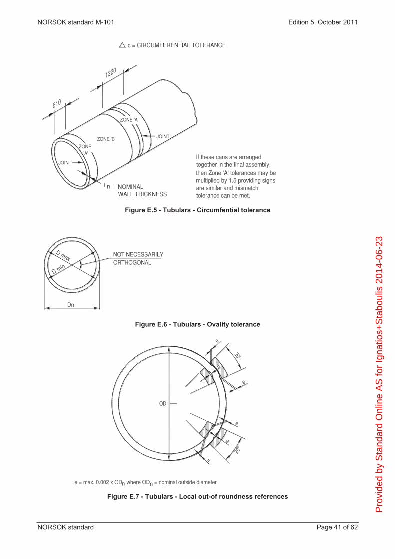
NORSOK standard M-101 Edition 5, October 2011
NORSOK standard Page 41 of 62
Figure E.5 - Tubulars - Circumfential tolerance
Figure E.6 - Tubulars - Ovality tolerance
Figure E.7 - Tubulars - Local out-of roundness references
Pro
vide
d by
Sta
ndar
d O
nlin
e A
S fo
r Ig
natio
s+S
tabo
ulis
201
4-06
-23

NORSOK standard M-101 Edition 5, October 2011
NORSOK standard Page 42 of 62
E.5.4 Panels
Type of deviation Figure Notation Ref. length
Allow. % of ref. length
Max. deviation mm
PANEL SHEET: Out of plane straightness, sagging/hogging, between girders
E.8
p1
W
0,15
15
Local buckles between stiffeners
E.8
p2
W1
0,5
5
GIRDERS/STIFFENERS:
Out of straightness in X and Y direction
E.8
g1
W
0,15%
10
Position deviation E.8 g2 Grid system
10
Inclination E.8 g3 Hg 0,8 10 Out of straightness of web normal to web (web buckles)
E.8
g4
Hg , W1
0,75
10
Figure E.8 - Deck panels tolerance references
Pro
vide
d by
Sta
ndar
d O
nlin
e A
S fo
r Ig
natio
s+S
tabo
ulis
201
4-06
-23

NORSOK standard M-101 Edition 5, October 2011
NORSOK standard Page 43 of 62
E.5.5 Girder nodes
Type of deviation Figure Notation Ref. length Allow. % of ref. length
Max. deviation mm
Position deviation of interfaces
E.9B E.9C
d1 Ref. centre line
- 5
Lateral and vertical straightness of node
E.9A f L 0,15 5
Lateral and vertical straightness of stiffeners
E.9A f1 L,H 0,1 5
Height of node
E.9B s - - 5
Pos. deviation stiffeners inclusive inclination
E.9B E.9C
d2 Ref. centre line
- 5
Position deviation column interfaces
E.9C d3 Ref.centre line
- 5
Baseplate flatness/rotation relative to Z axis
E.9A E.9B
b1 Ref. centre line
- 2
Pos.deviation baseplate relative to Z axis
E.9B d4 Ref.centre line
- 3
Pro
vide
d by
Sta
ndar
d O
nlin
e A
S fo
r Ig
natio
s+S
tabo
ulis
201
4-06
-23

NORSOK standard M-101 Edition 5, October 2011
NORSOK standard Page 44 of 62
Figure E.9 - Girder nodes tolerances
Pro
vide
d by
Sta
ndar
d O
nlin
e A
S fo
r Ig
natio
s+S
tabo
ulis
201
4-06
-23

NORSOK standard M-101 Edition 5, October 2011
NORSOK standard Page 45 of 62
E.5.6 Box nodes
Type of deviation Figure Notation Ref. length Allow. % of ref. length
Max. deviation mm
Position deviation of main box interface
E.10A d1 Ref. centre line
- 3
Out of straightness
E.10B d2 L 0,10 % 10
Buckling of plates
E.10C d3 H, W 0,5 % 10
Radial and tangential stub end deviation
E.10C E.10E
d4 Ref. centre line
- 5
Pos. deviation of load bearing stiffeners incl. inclination
E.10D d5 Ref. centre line
- 5
Offset of centrelines at centre of node
E.10E E.10F
d6 Ref. centre line
- 5
Figure E.10 - Box nodes tolerance references
Pro
vide
d by
Sta
ndar
d O
nlin
e A
S fo
r Ig
natio
s+S
tabo
ulis
201
4-06
-23

NORSOK standard M-101 Edition 5, October 2011
NORSOK standard Page 46 of 62
E.5.7 Tubular nodes
Type of deviation Figure Notation Ref. length Allow. % of ref. length
Max. deviation
mm Overlength of stub E.11A l2 L2 +25
-0 Overlength of node can barrel E.11.A l1 L1 +10
-0 Stub ends perpendicularity
E.11A p - 3
Radial and tangential stub end/ node cans position
E.12 V Grid system 0,2 of arc 6
Position of intersection point node can / stub
E.12 E Grid system 6
Internal stiffeners -Position -Inclination of web -Flange width -Bow of web -Rotation of flange -Eccentricity of flange on web -Height of stiffeners
E.11A E.11B E.11B E.11C E.11B
E.11B E.11B
P M B N
Lx h b
1,0 % 1,5 %
1,0 %
5 5 3 6 6 6
+10/-3 Local straightness of stubs/barrel E.11A f Wall
thickness 25 % 8
Straightness of barrel
E.11A L 1/1200 10
The centre line of stub shall be within 0,2 from the stub angle specified on the design drawings. Maximum position deviation measured at the intersection of stub end/node shall be 6 mm. For stubs longer than 1 stub diameter, the position deviation between can and stub may be taken at the 1 diameter location. Tolerances for circumference, out-of roundness (ovality), local out-of roundness, out-of circularity.
are defined in E.5.3 and shall not exceed 0,0025 X nominal diameter.
Pro
vide
d by
Sta
ndar
d O
nlin
e A
S fo
r Ig
natio
s+S
tabo
ulis
201
4-06
-23
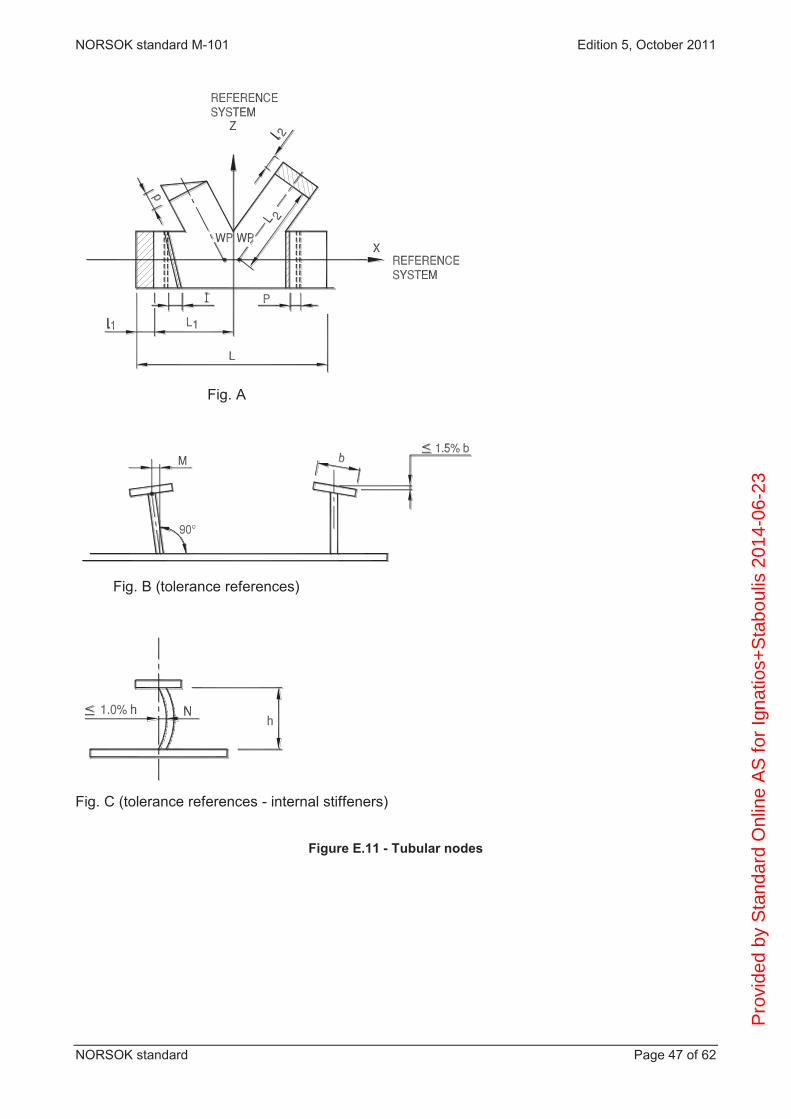
NORSOK standard M-101 Edition 5, October 2011
NORSOK standard Page 47 of 62
Fig. A
Fig. B (tolerance references)
Fig. C (tolerance references - internal stiffeners)
Figure E.11 - Tubular nodes
Pro
vide
d by
Sta
ndar
d O
nlin
e A
S fo
r Ig
natio
s+S
tabo
ulis
201
4-06
-23
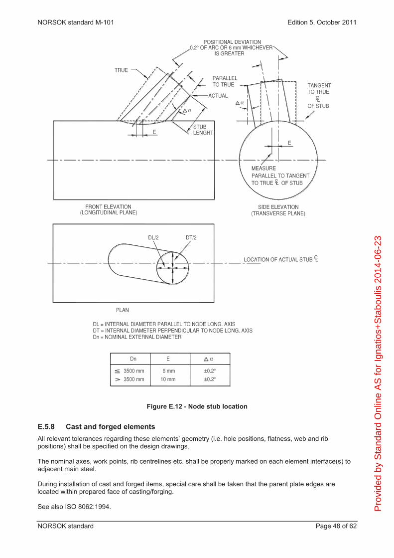
NORSOK standard M-101 Edition 5, October 2011
NORSOK standard Page 48 of 62
Figure E.12 - Node stub location
E.5.8 Cast and forged elements All relevant tolerances regarding these elements’ geometry (i.e. hole positions, flatness, web and rib positions) shall be specified on the design drawings. The nominal axes, work points, rib centrelines etc. shall be properly marked on each element interface(s) to adjacent main steel. During installation of cast and forged items, special care shall be taken that the parent plate edges are located within prepared face of casting/forging. See also ISO 8062:1994. P
rovi
ded
by S
tand
ard
Onl
ine
AS
for
Igna
tios+
Sta
boul
is 2
014-
06-2
3
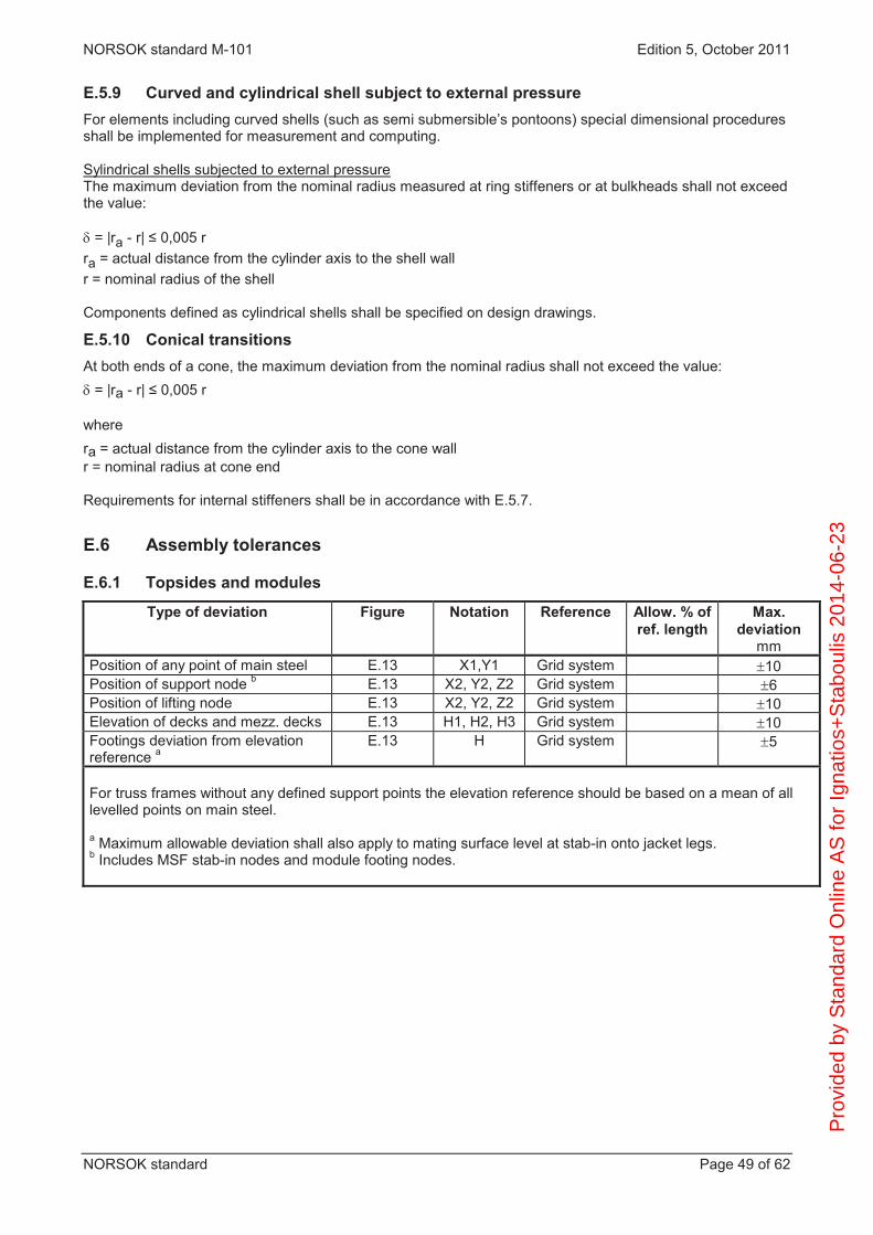
NORSOK standard M-101 Edition 5, October 2011
NORSOK standard Page 49 of 62
E.5.9 Curved and cylindrical shell subject to external pressure For elements including curved shells (such as semi submersible’s pontoons) special dimensional procedures shall be implemented for measurement and computing. Sylindrical shells subjected to external pressure The maximum deviation from the nominal radius measured at ring stiffeners or at bulkheads shall not exceed the value: = |ra - r| ≤ 0,005 r
ra = actual distance from the cylinder axis to the shell wall r = nominal radius of the shell Components defined as cylindrical shells shall be specified on design drawings.
E.5.10 Conical transitions At both ends of a cone, the maximum deviation from the nominal radius shall not exceed the value: = |ra - r| ≤ 0,005 r
where ra = actual distance from the cylinder axis to the cone wall r = nominal radius at cone end Requirements for internal stiffeners shall be in accordance with E.5.7.
E.6 Assembly tolerances
E.6.1 Topsides and modules
Type of deviation Figure Notation Reference Allow. % of ref. length
Max. deviation
mm Position of any point of main steel E.13 X1,Y1 Grid system 10 Position of support node b E.13 X2, Y2, Z2 Grid system 6 Position of lifting node E.13 X2, Y2, Z2 Grid system 10 Elevation of decks and mezz. decks E.13 H1, H2, H3 Grid system 10 Footings deviation from elevation reference a
E.13 H Grid system 5
For truss frames without any defined support points the elevation reference should be based on a mean of all levelled points on main steel. a Maximum allowable deviation shall also apply to mating surface level at stab-in onto jacket legs. b Includes MSF stab-in nodes and module footing nodes.
Pro
vide
d by
Sta
ndar
d O
nlin
e A
S fo
r Ig
natio
s+S
tabo
ulis
201
4-06
-23

NORSOK standard M-101 Edition 5, October 2011
NORSOK standard Page 50 of 62
Figure E.13 - Topside and module tolerance references
E.6.2 Jacket and other tubular frame structures
E.6.2.1 Assembly tolerances
Type of deviation Figure Notation Reference Max. deviation mm
Position deviation of centre of nodes
E.14A
x, y Grid system ±12
Rotation of node E.14A S ±6 Distance deviation between two nodes
E.14A ±20
Diagonal distance between column in each hor. plane
12
Position of leg ring stiffeners and diaphragms
±6
Inclination of ring stiffeners
6
Straightness of legs/chords
E.14B/C f L X±10
Straightness of braces
E.14C f L X±L/1000
Position of intersecting braces
Grid system 15
NOTE Local tolerances for sliding and pivoting ends shall be specified on the structural drawings.
P
rovi
ded
by S
tand
ard
Onl
ine
AS
for
Igna
tios+
Sta
boul
is 2
014-
06-2
3

NORSOK standard M-101 Edition 5, October 2011
NORSOK standard Page 51 of 62
Figure E.14 - Jacket and tubular frame structures - Assembly tolerances
Pro
vide
d by
Sta
ndar
d O
nlin
e A
S fo
r Ig
natio
s+S
tabo
ulis
201
4-06
-23

NORSOK standard M-101 Edition 5, October 2011
NORSOK standard Page 52 of 62
E.6.2.2 Final tolerances for jacket, interface jacket/MSF
Type of deviation Figure Notation Reference Max.
deviation mm
Horizontal position deviation of centre of stab-in cans
E.15
Vx, Vy
V = (Vx²+Vy²)
Grid system a
6 8
Jacket: Distance between centre of column to centre of any column at stab-in cans
E.15
F
L
12
Jacket: Mating surface level at stab-in
Grid system b
±3
MSF: Distance between centre of column to centre of any column at stab-in cans
E.15
F
L
6
Ovality of stab-in can
As in section E.5.3 b)
Horizontal position deviation of caissons, risers, J-tube
Grid system
6
a The position of the stab-in cans shall, if the situation allows, be related to the top-
side stab-in cones with the tolerances stated above. b The jacket legs shall by preference be cut within above tolerances after grout is cured.
If survey of the deck footings show out-of acceptable elevation/flatness tolerances (see E.6.1) the measured deviations shall be considered incorporated when cutting the legs in order to minimise loads due to differential settlements in footings.
Pro
vide
d by
Sta
ndar
d O
nlin
e A
S fo
r Ig
natio
s+S
tabo
ulis
201
4-06
-23

NORSOK standard M-101 Edition 5, October 2011
NORSOK standard Page 53 of 62
Figure E.15 - Final tolerance jacket interface jacket/MSF
E.6.2.3 Guides, sleeves, piles and clamps
The position deviation of the centre of pile guides/sleeves shall be 25 mm related to the coordinate system. Local alignment of sleeves is 20 mm. Radius of spacer plates is 5 mm.
E.6.2.4 Piles
Type of deviation Figure Notation Reference Max. deviation
mm
Length 100
Diameter between spacer plates
E.16
d1
As specified on
drawing
Diameter in driving head
E.16
d2
As specified on
drawing
End perpendicularity in driving head
E.16
P
As specified on
drawing
Pile markings 50
For general tolerances, see E.5.3.
Pro
vide
d by
Sta
ndar
d O
nlin
e A
S fo
r Ig
natio
s+S
tabo
ulis
201
4-06
-23

NORSOK standard M-101 Edition 5, October 2011
NORSOK standard Page 54 of 62
Figure E.16 - Piles tolerance references
E.6.2.5 Conductor guides
The position deviation of the centre of the conductor guides shall be 10 mm related to the coordinate system for top el. and 15 mm for the other elevations related to the same coordinate system. The maximum deviation of any conductor guide from the optimised centreline through all conductor guides shall not vary more than 15 mm.
E.6.2.6 Appurtenances
Caissons, J-tubes and risers.
Type of deviation Figure Notation Reference Max.deviation mm
Length - - - 25
E.6.3 Floating production units
E.6.3.1 Semi submersibles and tension leg platforms
Overall hull/substructure tolerances
Type of deviation Figure Reference Max. deviation mm
Global position of column top/bottom
E.17 E.18
Global grid system
15
Distance between top/bottom of two columns
E.17 E.18
30
Local position of column top/bottom E.19 Local grid system
5
Pro
vide
d by
Sta
ndar
d O
nlin
e A
S fo
r Ig
natio
s+S
tabo
ulis
201
4-06
-23
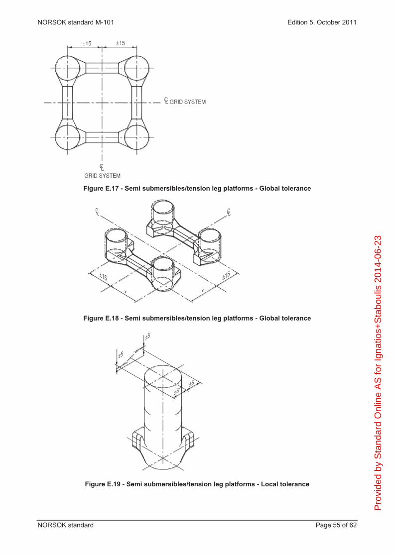
NORSOK standard M-101 Edition 5, October 2011
NORSOK standard Page 55 of 62
Figure E.17 - Semi submersibles/tension leg platforms - Global tolerance
Figure E.18 - Semi submersibles/tension leg platforms - Global tolerance
Figure E.19 - Semi submersibles/tension leg platforms - Local tolerance
Pro
vide
d by
Sta
ndar
d O
nlin
e A
S fo
r Ig
natio
s+S
tabo
ulis
201
4-06
-23

NORSOK standard M-101 Edition 5, October 2011
NORSOK standard Page 56 of 62
E.6.3.2 Ship
Ships should be fabricated using a grid system with origo in the aft perpendicular, and in accordance with E.3. Based on the grid system a reference system according to E.4.6.1 should be permanently marked onboard the ship.
E.6.4 Subsea structures Subsea structures should be fabricated according to tolerances given on drawings.
E.7 Fabrication tolerances for special items
E.7.1 Crane pedestal Crane pedestal tolerances shall be specified in a separate document to be prepared by the designer, taking into account the structural aspects as well as the mechanical functional tolerances and equipment interface tolerances.
E.7.2 Skid beams Skid beam tolerances shall be specified in a separate document to be prepared by the designer, taking into account the structural aspects as well as the mechanical functional tolerances and equipment interface tolerances.
E.7.3 Outfitting structure The following apply: this section covers all primary and secondary outfitting structures; the difference in elevation of deck plates and/or grating at joints shall not exceed 2 mm; plates and gratings shall be without visible warping; landing and stairway locations shall not deviate more than 25 mm from the dimensions shown on the AFC
drawings; fabrication of handrails shall be performed to such a degree of accuracy that when erected, the toprail
shall be continuous, straight, have smooth transitions and be level to the eye; members in the vertical plane shall not be out of plumb by more than 6 mm on each 3 000 mm section
and not more than 26 mm over the total height of the structure; wherever tolerances are not shown on the drawings, or specified elsewhere, fabrication work shall be
accurate to within 10 mm of all nominal dimensions; matching holes for bolted connections shall not exceed 2 mm difference in location.
E.7.4 Installation aids Installation aid structures such as primary and secondary guides and bumpers shall be fabricated and installed in accordance with acceptable tolerances for relevant elements/structures defined in this NORSOK standard. Specific tolerance requirements are shown on respective drawings, and shall be mandatory.
E.7.5 Grillages Load out grillage, barge grillage and seafastening shall be fabricated and installed in accordance with acceptable tolerances for relevant structures/elements defined in this NORSOK standard, see E.4.8. Specific tolerance requirements shall be shown on respective drawings and shall be mandatory.
E.7.6 Cranes See EN 1090-1:2009.
Pro
vide
d by
Sta
ndar
d O
nlin
e A
S fo
r Ig
natio
s+S
tabo
ulis
201
4-06
-23

NORSOK standard M-101 Edition 5, October 2011
NORSOK standard Page 57 of 62
Annex F (Informative)
Weld inspection, typical check points
General
Workshop/worksite in general. Storage and handling of material and welding consumables. Traceability Equipment: use, registration, maintenance, calibration and documentation. Routines for certification, registration, confirmation of validity and prolongation of welders
qualifications, approval by a third party organisation. Registration, confirmation of validity of NDT personnel certificates and approval by a third party
organisation. Job-package: only approved drawings, latest revision/isometrics and specifications are used.
Welding symbols according to ISO 2553. Weld numbering system and identification/traceability. Check that all welding coordinators are working according their job-descriptions, instructions and
routines. Checkpoints before welding
Drawing Material, marking/coding/traceability and handling. Bevelling/cutting, groove preparation, fit up and staggering of adjacent longitudinal welds. Welding equipment and use; tools, welding machine etc. (check of calibration/maintenance). Preheating and protection against wind, rain etc., if necessary. Purging gas if necessary (type and flow-rate). Procedure for tack-welding. Tack-welding (parameter control) and tack welders qualification. Handling of welding consumables. Cleaning, ready for welding.
Checkpoints during welding
Drawing available Handling of material and welding consumables. Groove geometry. Welding equipment and use: tools, welding machine etc. (check of calibration/maintenance). Preheating, method and temperature. Interpass temperature and protection against wind, rain etc., if necessary. Purging gas, if necessary (type and flow-rate). Welders approval for the welding work. Welding performance (placing of run layer, welding direction and sequence, staggering of stop/start,
cleaning between layers). WPS on work place available for the welder and check of various parameter listed in WPS and
measuring/calculating heat input (arc energy). Self control done by the welder.
Checkpoints after welding
Marking/traceability Are welder identification and WPS number marked closed to weld? Is the used WPS and welder qualification (welding certificate) relevant for the welded joint? Check of “self inspection” done by the welder. Check of weld geometry/size welding symbol on drawing/WPS. Check of weld surface, transition area and area close to the weld. Performing and documentation of PWHT, if necessary.
Pro
vide
d by
Sta
ndar
d O
nlin
e A
S fo
r Ig
natio
s+S
tabo
ulis
201
4-06
-23

NORSOK standard M-101 Edition 5, October 2011
NORSOK standard Page 58 of 62
Scope of NDT, NDT qualifications, reporting and documentation. Marking, cleaning Documentation review (weld summary list).
Pro
vide
d by
Sta
ndar
d O
nlin
e A
S fo
r Ig
natio
s+S
tabo
ulis
201
4-06
-23

NORSOK standard M-101 Edition 5, October 2011
NORSOK standard Page 59 of 62
Annex G (Normative)
Components in stainless steel and Ni-alloys
G.1 Scope The purpose of this annex is to specify modified or additional requirements to fabrication, welding and inspection of structural components in stainless steel and Ni-alloys.
G.2 Materials Typical materials can be type 316L austenitic stainless steel, 22 05 and 23 04 Duplex stainless steel, iron-nickel-chromium alloys (e.g. Alloy 800H/HT). Examples of components are foundation structures for equipment/pipe support in 316L or 22 05 Duplex, architectural external fire walls in 23 04 Duplex (Lean Duplex), flare tower platform in Alloy 800H/HT.
G.3 Qualification of welding procedures and welders
G.3.1 Welding procedure specification WPS shall be established in accordance with ISO 15609-1. All welding shall be by use of qualified WPSs. Qualification of welding procedures shall be as specified in G.3.2.
G.3.2 Qualification of welding procedures Welding procedures shall be qualified in accordance with ISO 15614-1 and the additional requirements of this annex. Charpy impact testing shall be performed as part of the qualification test when testing is required for the base material. Test temperature shall be as specified for the base material. For Duplex SS acceptance criteria shall be 27 J or a lateral expansion of minimum 0,38 mm (10 mm x 10 mm specimens). For austenitic SS and Ni alloys acceptance criteria shall be a lateral expansion of minimum 0,38 mm (10 mm x 10 mm specimens). Micro-structural examination and corrosion test shall be performed as part of the qualification test when these tests are required for the base material. As an example, micro-structural examination could be relevant for 22 05 Duplex. In case any of these tests are required, testing and acceptance criteria shall then be as specified in NORSOK M-601. Welding procedures established and qualified in accordance with NORSOK M-601 are acceptable for welding of structural components.
G.3.3 Welder and welding operators qualifications The requirements of 5.5 shall apply. For Ni alloys welders shall be qualified in accordance with ISO 9606-4.
G.4 Welding consumables Duplex SS
For welding of Duplex SS, a matching consumable with enhanced Ni content compared to the base material shall be used. P
rovi
ded
by S
tand
ard
Onl
ine
AS
for
Igna
tios+
Sta
boul
is 2
014-
06-2
3

NORSOK standard M-101 Edition 5, October 2011
NORSOK standard Page 60 of 62
Alloy 800H/HT For welding of Alloy 800H/HT, the consumables shall be of the high nickel-chromium type. Recommended consumables (DT = design temperature in ºC):
DT < 535: ENiCrFe-3 or ERNiCr-3 535 ≤ DT ≤ 815: ENiCrFe-2 or ERNiCr-3 DT > 815: ENiCrMo-3 or ERNiCrMo-3
Consumables for joining of dissimilar materials
For welding of type 316L SS to carbon steel, consumables should be of type 309MoL, alternatively a nickel based alloy. For welding of higher alloyed stainless steels to carbon steel, the same or higher alloyed filler metal, as used for welding the stainless steel to itself, shall be used.
G.5 General fabrication requirements Requirements for fabrication, welding and inspection of structural components in SS and Ni alloys shall follow the same classification principles as for other structural steel elements, as specified in this NORSOK standard. All fabrication shall be in accordance with recommendations given in EN 1011-3. Prefabrication of SS and Ni-alloys should be performed in a workshop, or parts thereof, which is reserved exclusively for those types of materials. Contamination of weld bevels and surrounding areas with low melting point metals such as copper, zinc, etc. are not acceptable. The welding processes listed in ISO 15614-1 are acceptable. Maximum interpass temperature shall be 150 °C. All welds shall be continuous. Intermittent welding is acceptable if the environment can be defined as dry and non-corrosive. Maximum cold forming shall be 10 % for austenitic SS, and 5 % for duplex SS and Ni alloys. For calculation of deformation rate, see 6.2. Straightening shall not be performed by application of heat. Welding of attachments in SS or Ni alloys to carbon steel structures shall comply with the requirements for the structure to which they are attached.
G.6 Non-destructive testing (NDT)
G.6.1 General The inspection category shall be decided by the designer in accordance with NORSOK N-004, and shall be specified on the design drawings.
G.6.2 Qualification of NDT-operators The requirements of 9.1 shall apply.
G.6.3 Extent of NDT The minimum extent of examination is given in Table G.1. Design drawings may show areas of welds where examination is mandatory. P
rovi
ded
by S
tand
ard
Onl
ine
AS
for
Igna
tios+
Sta
boul
is 2
014-
06-2
3

NORSOK standard M-101 Edition 5, October 2011
NORSOK standard Page 61 of 62
Table G.1 Minimum extent of NDT (%) Inspection category
Type of connection
Visual Examination
%
Extent of testing %
RT PT A Buttweld
T-connection Fillet/partial
100 100 100
100 - -
100 100 100
B Buttweld T-connection Fillet/partial
100 100 100
50 - -
100 100 100
C Buttweld T-connection Fillet/partial
100 100 100
20 - -
20 20 20
D All connections 100 - 2 to 5 E All connections 100 - -
G.6.4 Procedures and acceptance criteria Visual inspection and finish of welds:
shall be in accordance with 9.4 and 9.8; weld zones shall in addition be visually inspected on both sides of the weld (where access), and fulfil
the following criteria: the oxidation levels showing light brown to brown colour are acceptable; oxidation levels showing a narrow band of dark brown colour and intermittent spots of blue colour
are acceptable; darker or more extensive oxidation colours are not acceptable, and shall be chemically or
mechanically removed.
Radiographic testing shall be in accordance with 9.5 and 9.8. Radiographic testing may be replaced with ultrasonic examination for material thickness ≥ 12mm.
Ultrasonic examination shall be performed in accordance with ISO 22825. Personnel shall be qualified as described in 9.2. Acceptance criteria shall be in accordance with 9.8.4.
Penetrant testing shall be carried out in accordance with ISO 3452-1. Acceptance criteria shall be in accordance with 9.8.5.
G.7 Repair Repair welding may only be carried out twice in the same area.
Pro
vide
d by
Sta
ndar
d O
nlin
e A
S fo
r Ig
natio
s+S
tabo
ulis
201
4-06
-23

Pro
vide
d by
Sta
ndar
d O
nlin
e A
S fo
r Ig
natio
s+S
tabo
ulis
201
4-06
-23