NORSOK L-CR-003
41
NORSOK STANDARD COMMON REQUIREMENTS PIPING DETAILS L-CR-003 Rev. 1, January 1996
description
Piping Details
Transcript of NORSOK L-CR-003

NORSOK STANDARD
COMMON REQUIREMENTS
PIPING DETAILS
L-CR-003Rev. 1, January 1996

Please note that whilst every effort has been made to ensure the accuracy of the NORSOK standardsneither OLF nor TBL or any of their members will assume liability for any use thereof.
Piping details L-CR-003 Rev. 1, January 1996
NORSOK standard Page 1 of 6
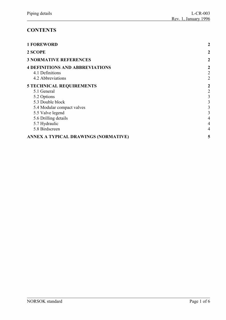
CONTENTS
1 FOREWORD 2
2 SCOPE 2
3 NORMATIVE REFERENCES 2
4 DEFINITIONS AND ABBREVIATIONS 24.1 Definitions 24.2 Abbreviations 2
5 TECHNICAL REQUIREMENTS 25.1 General 25.2 Options 35.3 Double block 35.4 Modular compact valves 35.5 Valve legend 35.6 Drilling details 45.7 Hydraulic 45.8 Birdscreen 4
ANNEX A TYPICAL DRAWINGS (NORMATIVE) 5
Piping details L-CR-003 Rev. 1, January 1996
NORSOK standard Page 2 of 6
1 FOREWORDNORSOK (The competitive standing of the Norwegian offshore sector) is the industry initiative toadd value, reduce cost and lead time and remove unnecessary activities in offshore fielddevelopments and operations.
The NORSOK standards are developed by the Norwegian petroleum industry as a part of theNORSOK initiative and are jointly issued by OLF (The Norwegian Oil Industry Association) andTBL (The Federation of Norwegian Engineering Industries). NORSOK standards are administeredby NTS (Norwegian Technology Standards Institution).
The purpose of this industry standard is to replace the individual oil company specifications for usein existing and future petroleum industry developments, subject to the individual company's reviewand application.
The NORSOK standards make extensive references to international standards. Where relevant, thecontents of this standard will be used to provide input to the international standardization process.Subject to implementation into international standards, this NORSOK standard will be withdrawn.
2 SCOPEThe standard defines the installation requirements for piping details.
3 NORMATIVE REFERENCESNORSOK L-CR-001 Piping and valves
4 DEFINITIONS AND ABBREVIATIONS
4.1 DefinitionsNormative references Shall mean normative in the application of NORSOK standards.Informative references Shall mean informative in the application of NORSOK standards.Shall Shall is an absolute requirement which shall be followed strictly in order
to conform with the standard.Should Should is a recommendation. Alternative solutions having the same
functionality and quality are acceptable.May May indicates a course of action that is permissible within the limits of
the standard (a permission).Can Can-requirements are conditional and indicates a possibility open to the
user of the standard.
4.2 AbbreviationsASME American National Standards Institute
5 TECHNICAL REQUIREMENTS
5.1 GeneralThis document is based upon using components from L-CR-001. However, components not coveredin L-CR-001 may be handled as special items.
Piping details L-CR-003 Rev. 1, January 1996
NORSOK standard Page 3 of 6
5.2 OptionsThis standard contains individual piping details. It is the intention that each project shall compile aset of standard sheets from this document applicable for the particular project.
Undesired sheets and options (E.g. 10A or 10B) should be subtracted by the project.
5.3 Double blockRequirements for double block (& bleed if applicable) shall be in accordance with P-CR-001. Thedetails shown in this document have been based on the assumption of applying double blockarrangement for ANSI Class 600 and above.
5.4 Modular compact valvesThe philosophy for use of modular compact valves will be included when these valves have beenincluded in the next revision of NORSOK standard for Piping and valves, L-CR-001. However,some of the details in this standard show Modular Compact Valves. The extent of use of thesevalves, is to be decided by project.
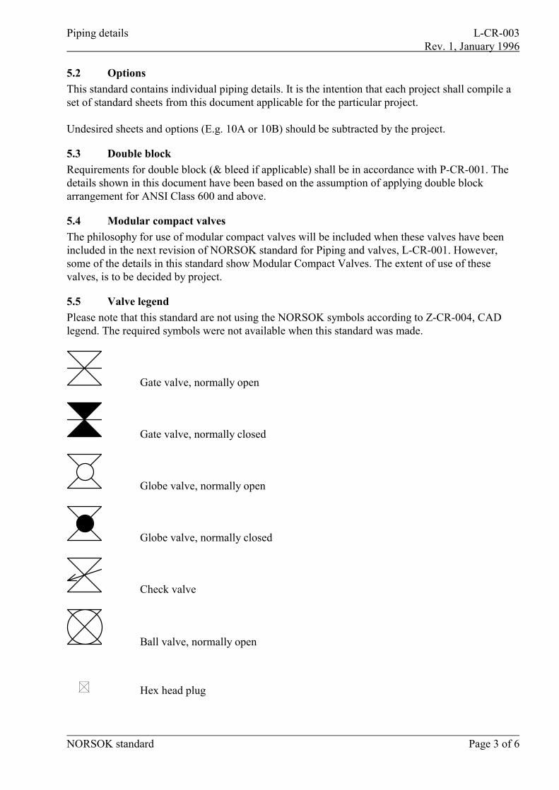
5.5 Valve legendPlease note that this standard are not using the NORSOK symbols according to Z-CR-004, CADlegend. The required symbols were not available when this standard was made.
Gate valve, normally open
Gate valve, normally closed
Globe valve, normally open
Globe valve, normally closed
Check valve
Ball valve, normally open
Hex head plug
Piping details L-CR-003 Rev. 1, January 1996
NORSOK standard Page 4 of 6
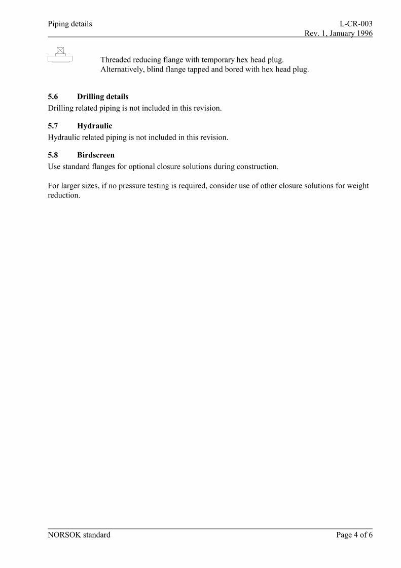
Threaded reducing flange with temporary hex head plug.Alternatively, blind flange tapped and bored with hex head plug.
5.6 Drilling detailsDrilling related piping is not included in this revision.
5.7 HydraulicHydraulic related piping is not included in this revision.
5.8 BirdscreenUse standard flanges for optional closure solutions during construction.
For larger sizes, if no pressure testing is required, consider use of other closure solutions for weightreduction.
Piping details L-CR-003Annex A Rev. 1, January 1996
NORSOK standard Page 5 of 6
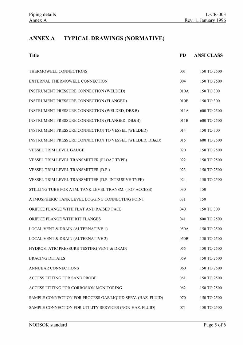
ANNEX A TYPICAL DRAWINGS (NORMATIVE)
Title PD ANSI CLASS
THERMOWELL CONNECTIONS 001 150 TO 2500
EXTERNAL THERMOWELL CONNECTION 004 150 TO 2500
INSTRUMENT PRESSURE CONNECTION (WELDED) 010A 150 TO 300
INSTRUMENT PRESSURE CONNECTION (FLANGED) 010B 150 TO 300
INSTRUMENT PRESSURE CONNECTION (WELDED, DB&B) 011A 600 TO 2500
INSTRUMENT PRESSURE CONNECTION (FLANGED, DB&B) 011B 600 TO 2500
INSTRUMENT PRESSURE CONNECTION TO VESSEL (WELDED) 014 150 TO 300
INSTRUMENT PRESSURE CONNECTION TO VESSEL (WELDED, DB&B) 015 600 TO 2500
VESSEL TRIM LEVEL GAUGE 020 150 TO 2500
VESSEL TRIM LEVEL TRANSMITTER (FLOAT TYPE) 022 150 TO 2500
VESSEL TRIM LEVEL TRANSMITTER (D.P.) 023 150 TO 2500
VESSEL TRIM LEVEL TRANSMITTER (D.P. INTRUSIVE TYPE) 024 150 TO 2500
STILLING TUBE FOR ATM. TANK LEVEL TRANSM. (TOP ACCESS) 030 150
ATMOSPHERIC TANK LEVEL LOGGING CONNECTING POINT 031 150
ORIFICE FLANGE WITH FLAT AND RAISED FACE 040 150 TO 300
ORIFICE FLANGE WITH RTJ FLANGES 041 600 TO 2500
LOCAL VENT & DRAIN (ALTERNATIVE 1) 050A 150 TO 2500
LOCAL VENT & DRAIN (ALTERNATIVE 2) 050B 150 TO 2500
HYDROSTATIC PRESSURE TESTING VENT & DRAIN 055 150 TO 2500
BRACING DETAILS 059 150 TO 2500
ANNUBAR CONNECTIONS 060 150 TO 2500
ACCESS FITTING FOR SAND PROBE 061 150 TO 2500
ACCESS FITTING FOR CORROSION MONITORING 062 150 TO 2500
SAMPLE CONNECTION FOR PROCESS GAS/LIQUID SERV. (HAZ. FLUID) 070 150 TO 2500
SAMPLE CONNECTION FOR UTILITY SERVICES (NON-HAZ. FLUID) 071 150 TO 2500
Piping details L-CR-003Annex A Rev. 1, January 1996
NORSOK standard Page 6 of 6
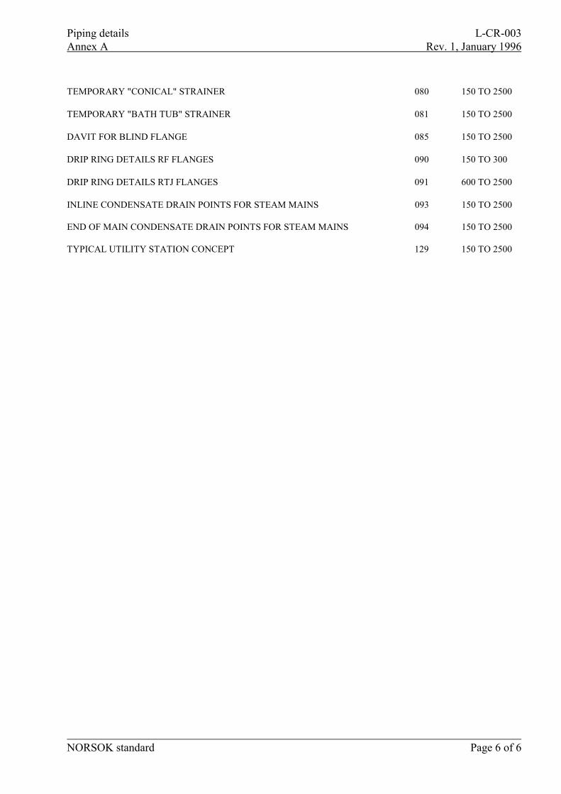
TEMPORARY "CONICAL" STRAINER 080 150 TO 2500
TEMPORARY "BATH TUB" STRAINER 081 150 TO 2500
DAVIT FOR BLIND FLANGE 085 150 TO 2500
DRIP RING DETAILS RF FLANGES 090 150 TO 300
DRIP RING DETAILS RTJ FLANGES 091 600 TO 2500
INLINE CONDENSATE DRAIN POINTS FOR STEAM MAINS 093 150 TO 2500
END OF MAIN CONDENSATE DRAIN POINTS FOR STEAM MAINS 094 150 TO 2500
TYPICAL UTILITY STATION CONCEPT 129 150 TO 2500
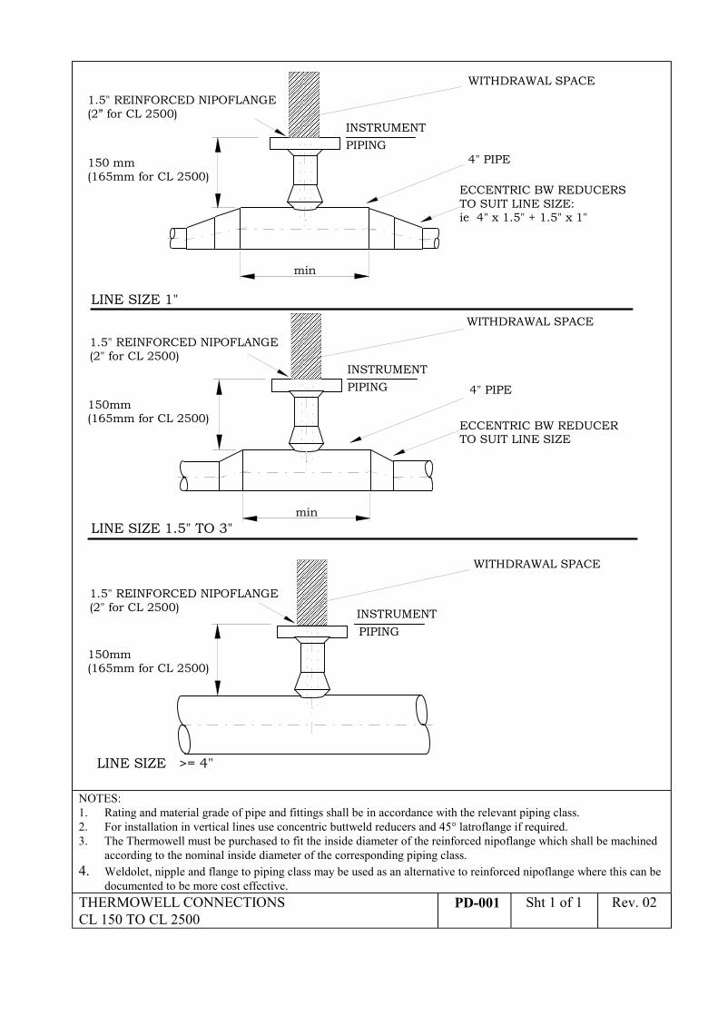
1.5" REINFORCED NIPOFLANGE(2” for CL 2500)
ECCENTRIC BW REDUCERSTO SUIT LINE SIZE:ie 4" x 1.5" + 1.5" x 1"
INSTRUMENTPIPING
150 mm(165mm for CL 2500)
4" PIPE
����������������������������������������������������������������������
WITHDRAWAL SPACE
INSTRUMENTPIPING
LINE SIZE 1"
LINE SIZE 1.5" TO 3"
1.5" REINFORCED NIPOFLANGE(2" for CL 2500)
ECCENTRIC BW REDUCERTO SUIT LINE SIZE
4" PIPE
INSTRUMENT
LINE SIZE >= 4"
1.5" REINFORCED NIPOFLANGE(2" for CL 2500)
PIPING
������������������������������������������������������������������������������������������
����������������������������������������������������������������������
WITHDRAWAL SPACE
WITHDRAWAL SPACE
min
min
150mm(165mm for CL 2500)
150mm(165mm for CL 2500)
NOTES:1. Rating and material grade of pipe and fittings shall be in accordance with the relevant piping class.2. For installation in vertical lines use concentric buttweld reducers and 45° latroflange if required.3. The Thermowell must be purchased to fit the inside diameter of the reinforced nipoflange which shall be machined
according to the nominal inside diameter of the corresponding piping class.4. Weldolet, nipple and flange to piping class may be used as an alternative to reinforced nipoflange where this can be
documented to be more cost effective.THERMOWELL CONNECTIONSCL 150 TO CL 2500
PD-001 Sht 1 of 1 Rev. 02
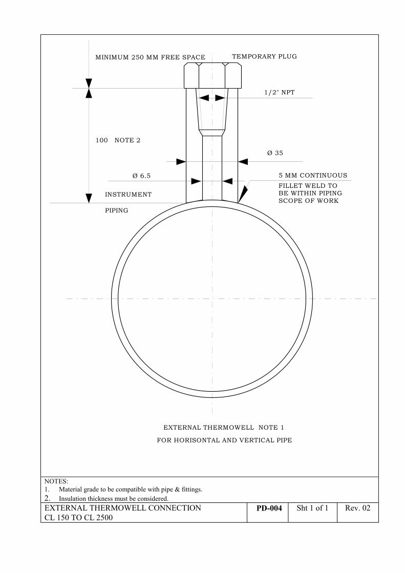
100 NOTE 2
INSTRUMENT
PIPING
TEMPORARY PLUGMINIMUM 250 MM FREE SPACE
FILLET WELD TOBE WITHIN PIPINGSCOPE OF WORK
5 MM CONTINUOUS
1/2" NPT
Ø 6.5
Ø 35
EXTERNAL THERMOWELL NOTE 1
FOR HORISONTAL AND VERTICAL PIPE
NOTES:1. Material grade to be compatible with pipe & fittings.2. Insulation thickness must be considered.EXTERNAL THERMOWELL CONNECTIONCL 150 TO CL 2500
PD-004 Sht 1 of 1 Rev. 02
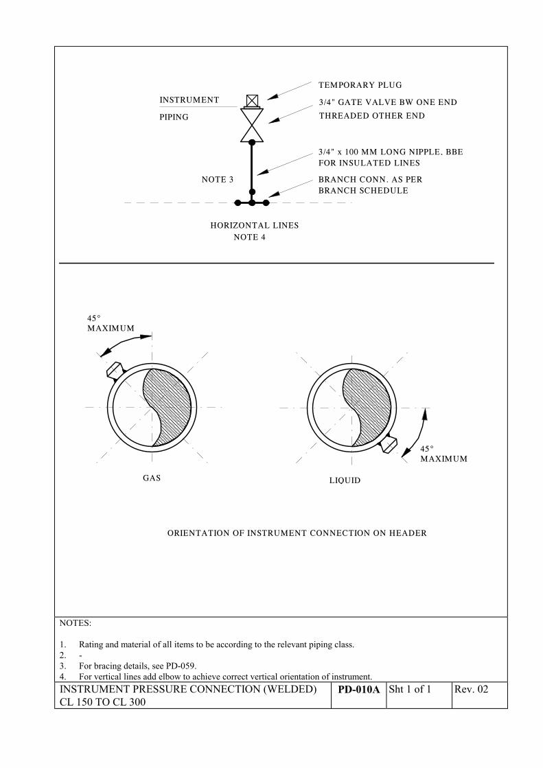
INSTRUMENT
PIPING
3/4" GATE VALVE BW ONE END
TEMPORARY PLUG
THREADED OTHER END
3/4" x 100 MM LONG NIPPLE, BBEFOR INSULATED LINES
BRANCH CONN. AS PERBRANCH SCHEDULE
HORIZONTAL LINESNOTE 4
����������������������������������������������������������������������������������������������������������������������������������������������������������������������������������������������������������������������������������������
45°MAXIMUM
GAS
��������������������������������������������������������������������������������������������������������������������������������������������������������������������������������������������������������������������������������������������������������
45°MAXIMUM
LIQUID
ORIENTATION OF INSTRUMENT CONNECTION ON HEADER
NOTE 3
NOTES:
1. Rating and material of all items to be according to the relevant piping class.2. -3. For bracing details, see PD-059.4. For vertical lines add elbow to achieve correct vertical orientation of instrument.INSTRUMENT PRESSURE CONNECTION (WELDED)CL 150 TO CL 300
PD-010A Sht 1 of 1 Rev. 02
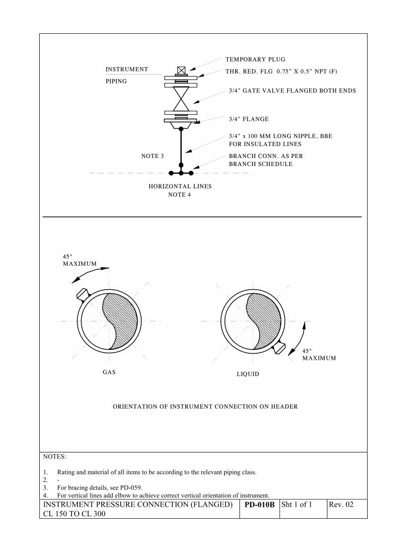
INSTRUMENT
PIPING
3/4" GATE VALVE FLANGED BOTH ENDS
3/4" x 100 MM LONG NIPPLE, BBEFOR INSULATED LINES
BRANCH CONN. AS PERBRANCH SCHEDULE
HORIZONTAL LINESNOTE 4
����������������������������������������������������������������������������������������������������������������������������������������������������������������������������������������������������������������������������������������
45°MAXIMUM
GAS
������������������������������������������������������������������������������������������������������������������������������������������������������������������������������������������������������������������������������������������������
45°MAXIMUM
LIQUID
ORIENTATION OF INSTRUMENT CONNECTION ON HEADER
3/4" FLANGE
NOTE 3
TEMPORARY PLUG
THR. RED. FLG 0.75” X 0.5” NPT (F)
NOTES:
1. Rating and material of all items to be according to the relevant piping class.2. -3. For bracing details, see PD-059.4. For vertical lines add elbow to achieve correct vertical orientation of instrument.INSTRUMENT PRESSURE CONNECTION (FLANGED)CL 150 TO CL 300
PD-010B Sht 1 of 1 Rev. 02
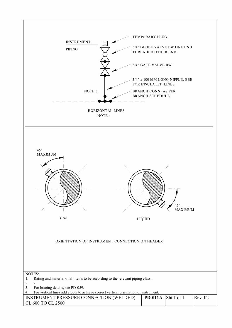
INSTRUMENT
PIPING
3/4" GATE VALVE BW
3/4" x 100 MM LONG NIPPLE, BBEFOR INSULATED LINES
BRANCH CONN. AS PERBRANCH SCHEDULE
HORIZONTAL LINESNOTE 4
������������������������������������������������������������������������������������������������������������������������������������������������������������������������������������������������������������������������
45°MAXIMUM
GAS
����������������������������������������������������������������������������������������������������������������������������������������������������������������������������������������������������������������������������������������
45°MAXIMUM
LIQUID
ORIENTATION OF INSTRUMENT CONNECTION ON HEADER
NOTE 3
3/4" GLOBE VALVE BW ONE ENDTHREADED OTHER END
TEMPORARY PLUG
NOTES:1. Rating and material of all items to be according to the relevant piping class.2. -3. For bracing details, see PD-059.4. For vertical lines add elbow to achieve correct vertical orientation of instrument.INSTRUMENT PRESSURE CONNECTION (WELDED)CL 600 TO CL 2500
PD-011A Sht 1 of 1 Rev. 02
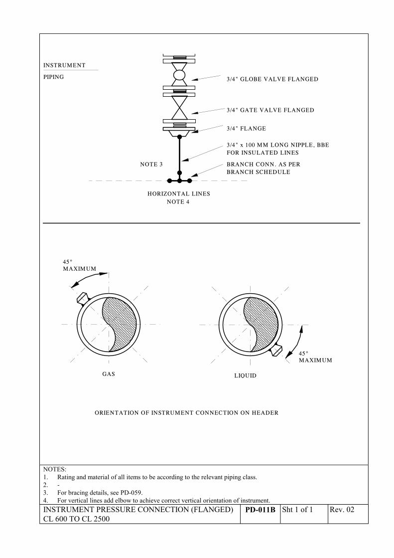
INSTRUMENT
PIPING
3/4" GATE VALVE FLANGED
3/4" x 100 MM LONG NIPPLE, BBEFOR INSULATED LINES
BRANCH CONN. AS PERBRANCH SCHEDULE
HORIZONTAL LINESNOTE 4
��������������������������������������������������������������������������������������������������������������������������������������������������������������������������������������������������������������������������������
45°MAXIMUM
GAS
���������������������������������������������������������������������������������������������������������������������������������������������������������������������������������������������������������������������������������������������������������������������������������������
45°MAXIMUM
LIQUID
ORIENTATION OF INSTRUMENT CONNECTION ON HEADER
3/4" FLANGE
NOTE 3
3/4" GLOBE VALVE FLANGED
NOTES:1. Rating and material of all items to be according to the relevant piping class.2. -3. For bracing details, see PD-059.4. For vertical lines add elbow to achieve correct vertical orientation of instrument.INSTRUMENT PRESSURE CONNECTION (FLANGED)CL 600 TO CL 2500
PD-011B Sht 1 of 1 Rev. 02
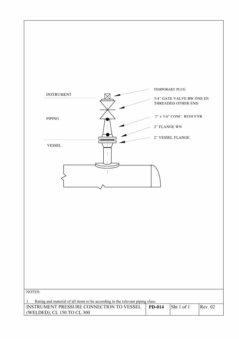
INSTRUMENT
PIPING
3/4" GATE VALVE BW ONE ENTHREADED OTHER END
2" VESSEL FLANGE
VESSEL
2" x 3/4" CONC. REDUCER
2" FLANGE WN
TEMPORARY PLUG
NOTES:
1. Rating and material of all items to be according to the relevant piping class.INSTRUMENT PRESSURE CONNECTION TO VESSEL(WELDED), CL 150 TO CL 300
PD-014 Sht 1 of 1 Rev. 02
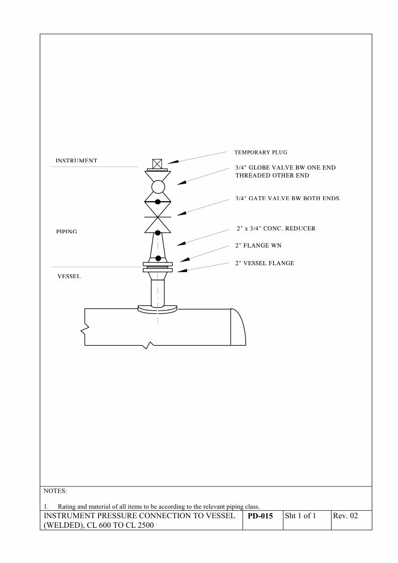
INSTRUMENT
PIPING
3/4" GATE VALVE BW BOTH ENDS
2" VESSEL FLANGE
VESSEL
2" x 3/4" CONC. REDUCER
2" FLANGE WN
TEMPORARY PLUG
3/4" GLOBE VALVE BW ONE ENDTHREADED OTHER END
NOTES:
1. Rating and material of all items to be according to the relevant piping class.INSTRUMENT PRESSURE CONNECTION TO VESSEL(WELDED), CL 600 TO CL 2500
PD-015 Sht 1 of 1 Rev. 02
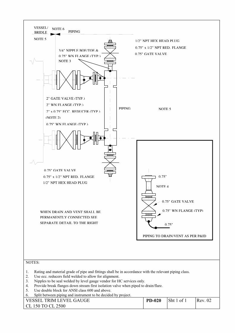
VESSEL/ NOTE 6PIPING
1/2" NPT HEX HEAD PLUG
0.75" x 1/2" NPT RED. FLANGE
0.75" GATE VALVE
2" GATE VALVE (TYP.)
PIPING2" WN FLANGE (TYP.)
2" x 0.75" ECC. REDUCER (TYP.)
0.75" WN FLANGE (TYP.)
WHEN DRAIN AND VENT SHALL BE
PERMANENTLY CONNECTED SEE
SEPARATE DETAIL TO THE RIGHT
(NOTE 2)
PIPING TO DRAIN/VENT AS PER P&ID
0.75"
0.75"
1/2" NPT HEX HEAD PLUG
0.75" x 1/2" NPT RED. FLANGE
0.75" GATE VALVE
0.75" GATE VALVE
NOTE 3
NOTE 5
NOTE 4
0.75" WN FLANGE (TYP.)
3/4" NIPPLE BOE/TOE &
BRIDLE
NOTE 5
0.75" WN FLANGE (TYP)
NOTES:
1. Rating and material grade of pipe and fittings shall be in accordance with the relevant piping class.2. Use ecc. reducers field welded to allow for alignment.3. Nipples to be seal welded by level gauge vendor for HC services only.4. Provide break flanges down stream first isolation valve when piped to drain/flare.5. Use double block for ANSI class 600 and above.6. Split between piping and instrument to be decided by project.VESSEL TRIM LEVEL GAUGECL 150 TO CL 2500
PD-020 Sht 1 of 1 Rev. 02
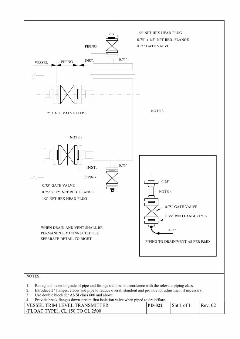
VESSEL PIPING
2" GATE VALVE (TYP.)
WHEN DRAIN AND VENT SHALL BE
PERMANENTLY CONNECTED SEE
SEPARATE DETAIL TO RIGHT
1/2" NPT HEX HEAD PLUG
0.75" x 1/2" NPT RED. FLANGE
0.75" GATE VALVE
INST.
INST.
PIPING
0.75"
0.75"
NOTE 3
PIPING
1/2" NPT HEX HEAD PLUG
0.75" x 1/2" NPT RED. FLANGE
0.75" GATE VALVE
PIPING TO DRAIN/VENT AS PER P&ID
0.75"
0.75"
0.75" GATE VALVE
NOTE 3
NOTE 4
0.75" WN FLANGE (TYP)
NOTES:
1. Rating and material grade of pipe and fittings shall be in accordance with the relevant piping class.2. Introduce 2" flanges, elbow and pipe to reduce overall standout and provide for adjustment if necessary.3. Use double block for ANSI class 600 and above.4. Provide break flanges down stream first isolation valve when piped to drain/flare.VESSEL TRIM LEVEL TRANSMITTER(FLOAT TYPE), CL 150 TO CL 2500
PD-022 Sht 1 of 1 Rev. 02
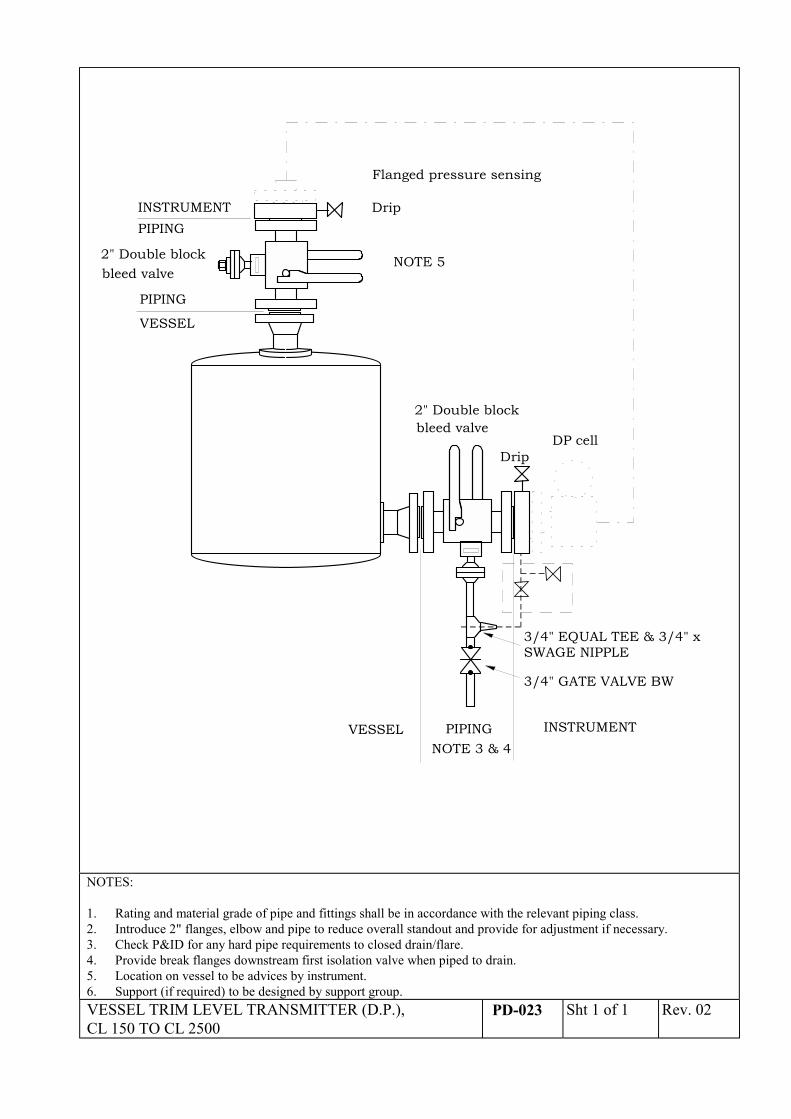
VESSEL
INSTRUMENTPIPING
2" Double block bleed valve
Drip
2" Double block bleed valve
Flanged pressure sensing
DP cell
PIPING
INSTRUMENTPIPINGVESSELNOTE 3 & 4
NOTE 5
3/4" EQUAL TEE & 3/4" xSWAGE NIPPLE
3/4" GATE VALVE BW
Drip
NOTES:
1. Rating and material grade of pipe and fittings shall be in accordance with the relevant piping class.2. Introduce 2" flanges, elbow and pipe to reduce overall standout and provide for adjustment if necessary.3. Check P&ID for any hard pipe requirements to closed drain/flare.4. Provide break flanges downstream first isolation valve when piped to drain.5. Location on vessel to be advices by instrument.6. Support (if required) to be designed by support group.VESSEL TRIM LEVEL TRANSMITTER (D.P.),CL 150 TO CL 2500
PD-023 Sht 1 of 1 Rev. 02
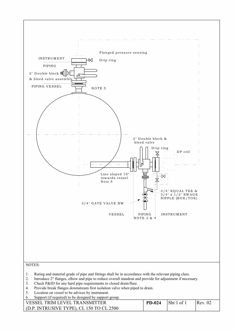
INSTR U M E NT
PIP ING
2" D ouble b lock
& b leed va lve assem bly
D rip ring
2" D ouble b lock & b leed va lve
F langed pressure sensing
D P cell
P IP ING V ESSE L
INSTR U M E NTPIP INGVESSELN O TE 3 & 4
N O TE 5
L ine s loped 10°tow ards vesselN ote 5
3/4" EQ U AL TEE &3/4" x 1/2" SW AG EN IPPLE (B O E/TO E )
3/4" G ATE V ALVE B W
D rip ring
NOTES:
1. Rating and material grade of pipe and fittings shall be in accordance with the relevant piping class.2. Introduce 2" flanges, elbow and pipe to reduce overall standout and provide for adjustment if necessary.3. Check P&ID for any hard pipe requirements to closed drain/flare.4. Provide break flanges downstream first isolation valve when piped to drain.5. Location on vessel to be advices by instrument.6. Support (if required) to be designed by support group.VESSEL TRIM LEVEL TRANSMITTER(D.P. INTRUSIVE TYPE), CL 150 TO CL 2500
PD-024 Sht 1 of 1 Rev. 02
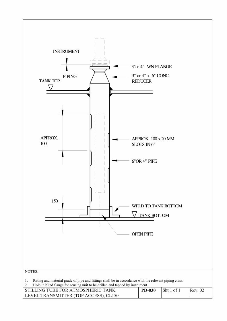
APPROX.100
150
INSTRUMENT
3"or 4” WN FLANGE
3" or 4” x 6" CONC.REDUCER
APPROX. 100 x 20 MMSLOTS IN 6"
6"OR 4” PIPE
WELD TO TANK BOTTOM
PIPINGTANK TOP
TANK BOTTOM
OPEN PIPE
NOTES:
1. Rating and material grade of pipe and fittings shall be in accordance with the relevant piping class.2. Hole in blind flange for sensing unit to be drilled and tapped by instrument.STILLING TUBE FOR ATMOSPHERIC TANKLEVEL TRANSMITTER (TOP ACCESS), CL150
PD-030 Sht 1 of 1 Rev. 02
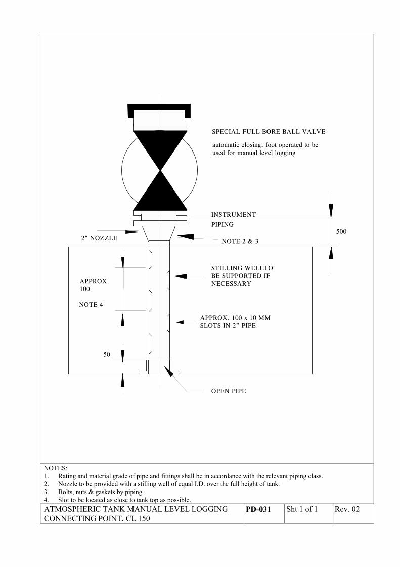
APPROX.100
50
OPEN PIPE
INSTRUMENT
PIPING
NOTE 2 & 3
STILLING WELLTOBE SUPPORTED IFNECESSARY
NOTE 4
2" NOZZLE500
automatic closing, foot operated to beused for manual level logging
SPECIAL FULL BORE BALL VALVE
APPROX. 100 x 10 MMSLOTS IN 2” PIPE
NOTES:1. Rating and material grade of pipe and fittings shall be in accordance with the relevant piping class.2. Nozzle to be provided with a stilling well of equal I.D. over the full height of tank.3. Bolts, nuts & gaskets by piping.4. Slot to be located as close to tank top as possible.ATMOSPHERIC TANK MANUAL LEVEL LOGGINGCONNECTING POINT, CL 150
PD-031 Sht 1 of 1 Rev. 02
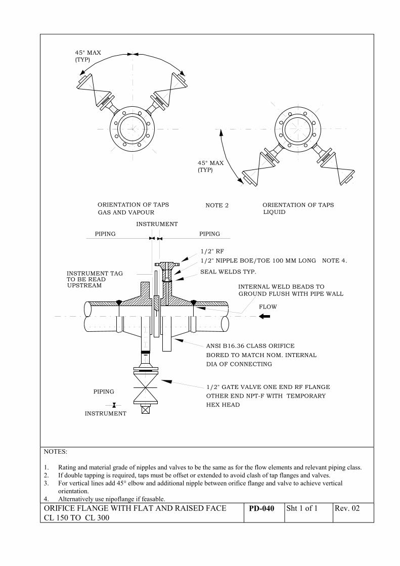
ORIENTATION OF TAPSGAS AND VAPOUR
ORIENTATION OF TAPSLIQUID
BORED TO MATCH NOM. INTERNALANSI B16.36 CLASS ORIFICE
DIA OF CONNECTING
INTERNAL WELD BEADS TOGROUND FLUSH WITH PIPE WALL
FLOW
INSTRUMENT TAGTO BE READUPSTREAM
SEAL WELDS TYP.
����������������������������������������������������������
������������������������������������������������������������������������������������������������������������
��������������������������������������������������
��������������������������������������������������������������������������������������������������������
INSTRUMENT
������������������������
������
��������������������������������
����������
������������������������������������
45° MAX(TYP)
1/2" NIPPLE BOE/TOE 100 MM LONG NOTE 4.1/2" RF
INSTRUMENT
PIPING
PIPING PIPING
1/2" GATE VALVE ONE END RF FLANGEOTHER END NPT-F WITH TEMPORARYHEX HEAD
45° MAX(TYP)
NOTE 2
NOTES:
1. Rating and material grade of nipples and valves to be the same as for the flow elements and relevant piping class.2. If double tapping is required, taps must be offset or extended to avoid clash of tap flanges and valves.3. For vertical lines add 45° elbow and additional nipple between orifice flange and valve to achieve vertical
orientation.4. Alternatively use nipoflange if feasable.ORIFICE FLANGE WITH FLAT AND RAISED FACECL 150 TO CL 300
PD-040 Sht 1 of 1 Rev. 02
������������
���������������
���������������������������������������������������������������������������������������������������������
����������������������������������������������������
���������������������������
�����������������������������������������������������������������������������������������������������������������������
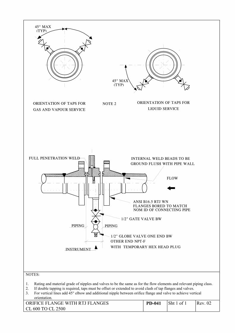
ORIENTATION OF TAPS FOR
GAS AND VAPOUR SERVICE
ORIENTATION OF TAPS FOR
LIQUID SERVICE
���������������������������������
INTERNAL WELD BEADS TO BEGROUND FLUSH WITH PIPE WALL
FLOW
ANSI B16.5 RTJ WNFLANGES BORED TO MATCHNOM ID OF CONNECTING PIPE
PIPINGPIPING
FULL PENETRATION WELD��� ������
INSTRUMENT
������������
45° MAX(TYP)
1/2" GATE VALVE BW
45° MAX(TYP)
NOTE 2
1/2" GLOBE VALVE ONE END BWOTHER END NPT-F
WITH TEMPORARY HEX HEAD PLUG
NOTES:
1. Rating and material grade of nipples and valves to be the same as for the flow elements and relevant piping class.2. If double tapping is required, taps must be offset or extended to avoid clash of tap flanges and valves.3. For vertical lines add 45° elbow and additional nipple between orifice flange and valve to achieve vertical
orientation.ORIFICE FLANGE WITH RTJ FLANGESCL 600 TO CL 2500
PD-041 Sht 1 of 1 Rev. 02
N O T E 4
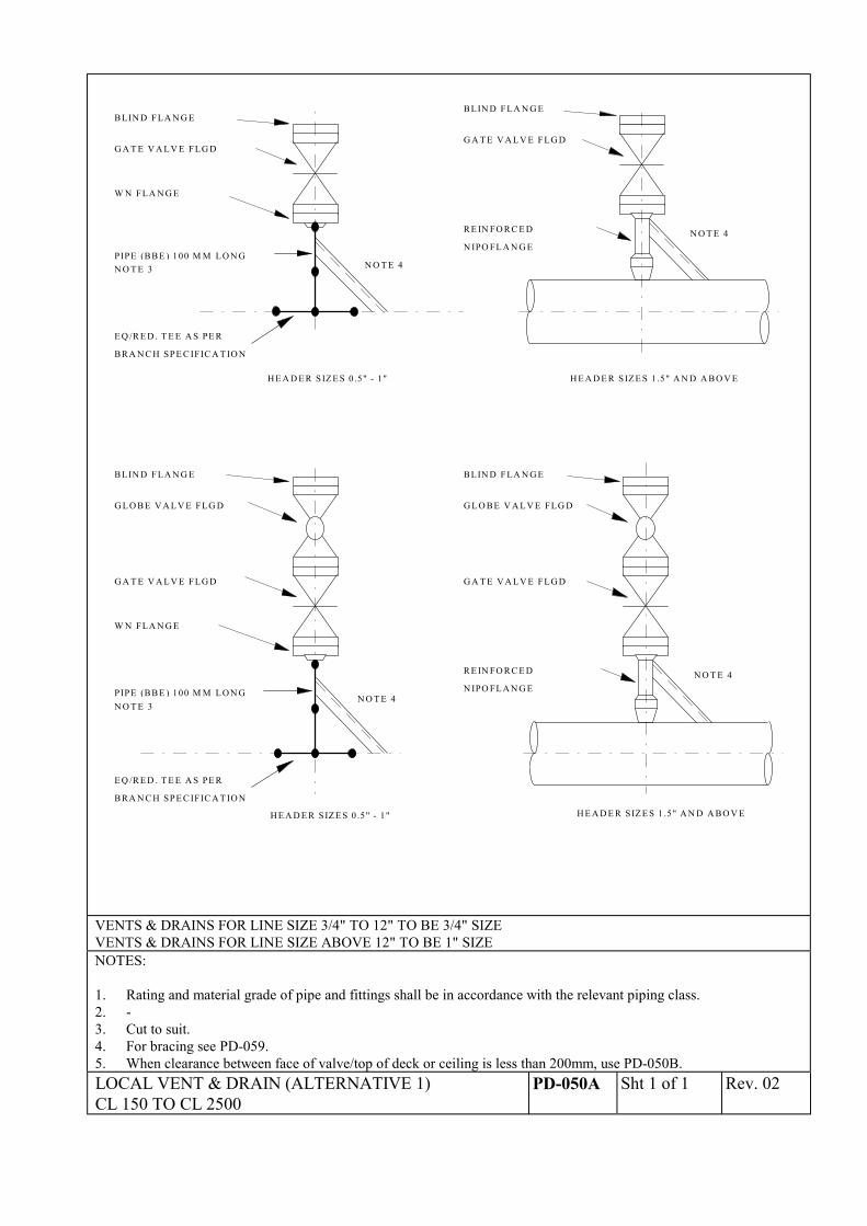
B LIN D FLA N G E
G A T E V A LV E FLG D
R E IN FO R C E D
H E A D E R SIZE S 1 .5" A N D A B O V E
N O T E 4
B LIN D FLA N G E
G A T E V A LV E FLG D
R E IN FO R C E D
H E A D E R SIZE S 1 .5" A N D A B O V E
G LO B E V A LV E FLG D
B LIN D FLA N G E
G A T E V A LV E FLG D
H E A D E R SIZ E S 0 .5" - 1"
W N FLA N G E
PIPE (B BE ) 100 M M LO N GN O T E 3
B LIN D FLA N G E
G A T E V A LV E FLG D
G LO B E V A LV E FLG D
H E A D E R SIZ E S 0 .5" - 1"
PIPE (B BE ) 100 M M LO N G
W N FLA N G E
N O T E 3
N O T E 4
N O T E 4N IPO FLA N G E
N IPO FLA N G E
E Q /R E D . T E E A S PE R
B RA N C H SPE C IFIC A T IO N
E Q /R E D . T E E A S PE R
B RA N C H SPE C IFIC A T IO N
VENTS & DRAINS FOR LINE SIZE 3/4" TO 12" TO BE 3/4" SIZEVENTS & DRAINS FOR LINE SIZE ABOVE 12" TO BE 1" SIZENOTES:
1. Rating and material grade of pipe and fittings shall be in accordance with the relevant piping class.2. -3. Cut to suit.4. For bracing see PD-059.5. When clearance between face of valve/top of deck or ceiling is less than 200mm, use PD-050B.LOCAL VENT & DRAIN (ALTERNATIVE 1)CL 150 TO CL 2500
PD-050A Sht 1 of 1 Rev. 02
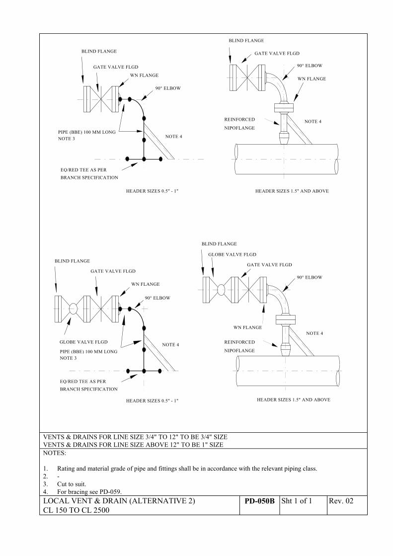
NOTE 4REINFORCED
HEADER SIZES 1.5" AND ABOVE
NOTE 4
HEADER SIZES 1.5" AND ABOVE
HEADER SIZES 0.5" - 1"
PIPE (BBE) 100 MM LONGNOTE 3
BLIND FLANGE
GATE VALVE FLGD
GLOBE VALVE FLGD
HEADER SIZES 0.5" - 1"
PIPE (BBE) 100 MM LONG
WN FLANGE
NOTE 3
NOTE 4
NOTE 4
NIPOFLANGE
BLIND FLANGE
GLOBE VALVE FLGD
GATE VALVE FLGD
WN FLANGE
REINFORCED
NIPOFLANGE
BLIND FLANGE
GATE VALVE FLGD
WN FLANGE
BLIND FLANGE
GATE VALVE FLGD
WN FLANGE
EQ/RED TEE AS PER
BRANCH SPECIFICATION
EQ/RED TEE AS PERBRANCH SPECIFICATION
90° ELBOW
90° ELBOW
90° ELBOW
90° ELBOW
VENTS & DRAINS FOR LINE SIZE 3/4" TO 12" TO BE 3/4" SIZEVENTS & DRAINS FOR LINE SIZE ABOVE 12" TO BE 1" SIZENOTES:
1. Rating and material grade of pipe and fittings shall be in accordance with the relevant piping class.2. -3. Cut to suit.4. For bracing see PD-059.LOCAL VENT & DRAIN (ALTERNATIVE 2)CL 150 TO CL 2500
PD-050B Sht 1 of 1 Rev. 02
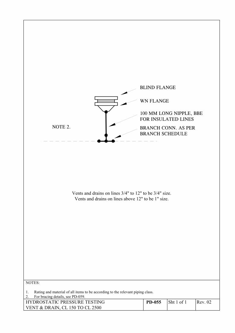
100 MM LONG NIPPLE, BBEFOR INSULATED LINES
BRANCH CONN. AS PERBRANCH SCHEDULE
WN FLANGE
BLIND FLANGE
NOTE 2.
Vents and drains on lines 3/4" to 12" to be 3/4" size.Vents and drains on lines above 12" to be 1" size.
NOTES:
1. Rating and material of all items to be according to the relevant piping class.2. For bracing details, see PD-059.HYDROSTATIC PRESSURE TESTINGVENT & DRAIN, CL 150 TO CL 2500
PD-055 Sht 1 of 1 Rev. 02
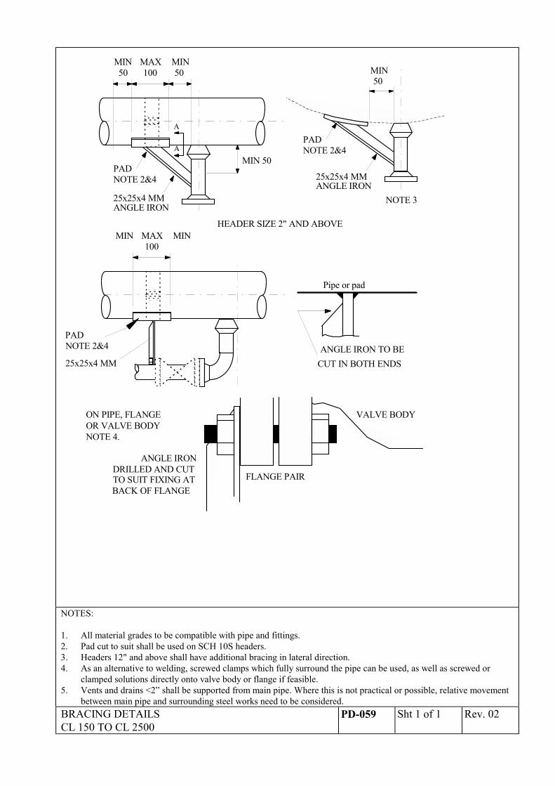
A
AMIN 50
50 100 50MIN MAX MIN
PADNOTE 2&4
25x25x4 MMANGLE IRON
PADNOTE 2&4
25x25x4 MMANGLE IRON
50MIN
NOTE 3
HEADER SIZE 2" AND ABOVE
CUT IN BOTH ENDSANGLE IRON TO BE
BACK OF FLANGETO SUIT FIXING ATDRILLED AND CUT
VALVE BODY
Pipe or pad
100MIN MAX MIN
PADNOTE 2&4
25x25x4 MM
ANGLE IRON
ON PIPE, FLANGEOR VALVE BODYNOTE 4.
FLANGE PAIR
NOTES:
1. All material grades to be compatible with pipe and fittings.2. Pad cut to suit shall be used on SCH 10S headers.3. Headers 12" and above shall have additional bracing in lateral direction.4. As an alternative to welding, screwed clamps which fully surround the pipe can be used, as well as screwed or
clamped solutions directly onto valve body or flange if feasible.5. Vents and drains <2” shall be supported from main pipe. Where this is not practical or possible, relative movement
between main pipe and surrounding steel works need to be considered.BRACING DETAILSCL 150 TO CL 2500
PD-059 Sht 1 of 1 Rev. 02
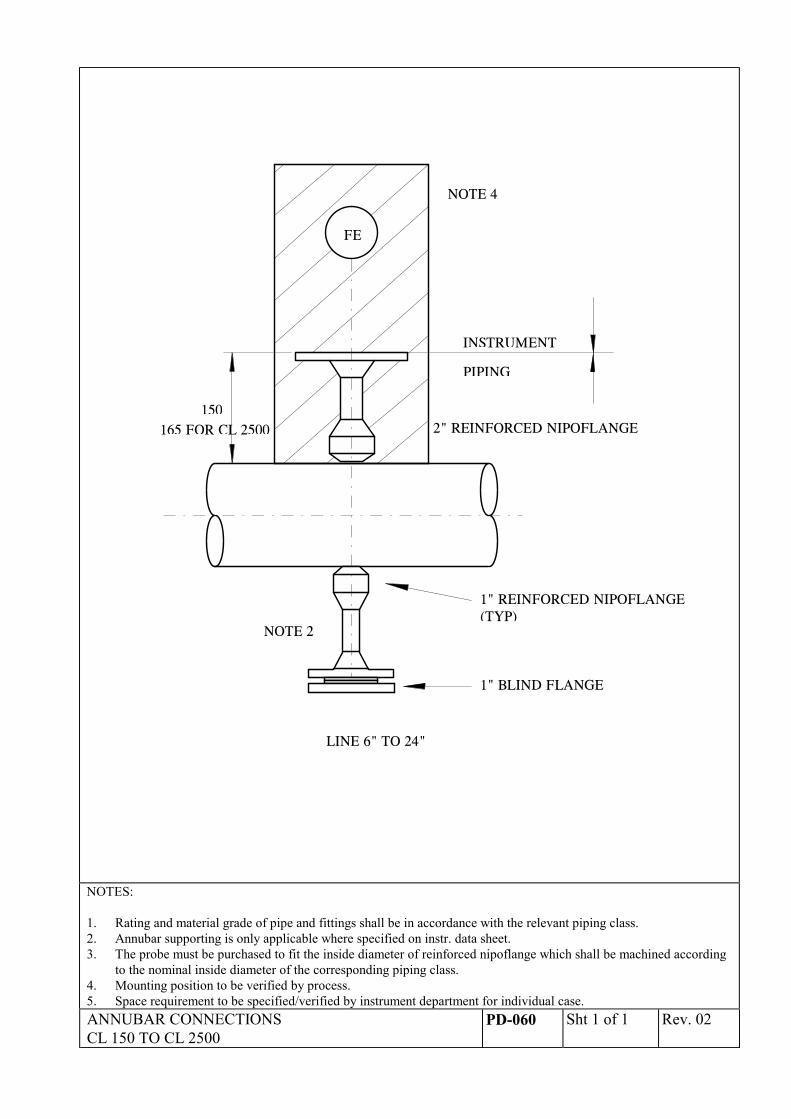
FE
NOTE 2
1" REINFORCED NIPOFLANGE
1" BLIND FLANGE
(TYP)
150
INSTRUMENT
PIPING
LINE 6" TO 24"
NOTE 4
2" REINFORCED NIPOFLANGE165 FOR CL 2500
NOTES:
1. Rating and material grade of pipe and fittings shall be in accordance with the relevant piping class.2. Annubar supporting is only applicable where specified on instr. data sheet.3. The probe must be purchased to fit the inside diameter of reinforced nipoflange which shall be machined according
to the nominal inside diameter of the corresponding piping class.4. Mounting position to be verified by process.5. Space requirement to be specified/verified by instrument department for individual case.ANNUBAR CONNECTIONSCL 150 TO CL 2500
PD-060 Sht 1 of 1 Rev. 02
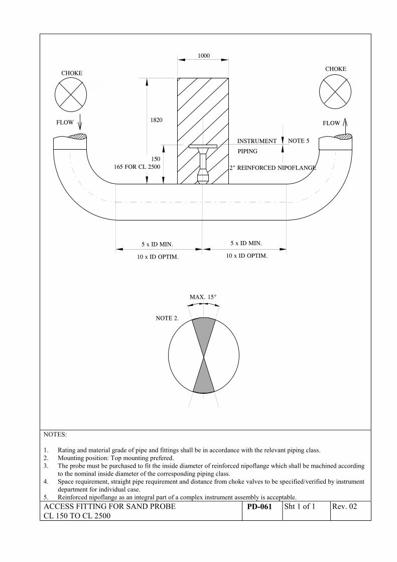
150
INSTRUMENT
PIPING
2" REINFORCED NIPOFLANGE
1820
1000
��������������������������������������������������������
������������������������������������������������������
5 x ID MIN.
10 x ID OPTIM.
5 x ID MIN.
10 x ID OPTIM.
CHOKECHOKE
FLOW FLOW
MAX. 15°
NOTE 2.
NOTE 5
165 FOR CL 2500
NOTES:
1. Rating and material grade of pipe and fittings shall be in accordance with the relevant piping class.2. Mounting position: Top mounting prefered.3. The probe must be purchased to fit the inside diameter of reinforced nipoflange which shall be machined according
to the nominal inside diameter of the corresponding piping class.4. Space requirement, straight pipe requirement and distance from choke valves to be specified/verified by instrument
department for individual case.5. Reinforced nipoflange as an integral part of a complex instrument assembly is acceptable.ACCESS FITTING FOR SAND PROBECL 150 TO CL 2500
PD-061 Sht 1 of 1 Rev. 02
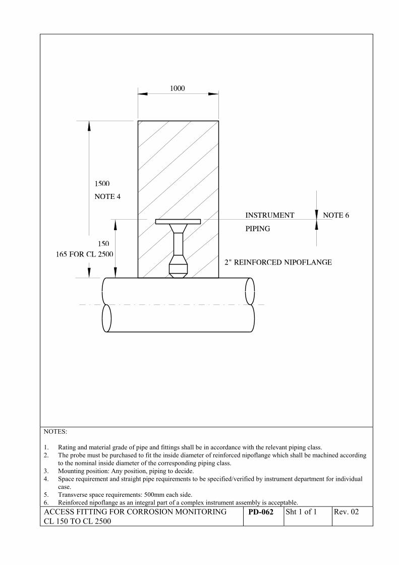
150
INSTRUMENT
PIPING
2" REINFORCED NIPOFLANGE
NOTE 4
1500
1000
165 FOR CL 2500
NOTE 6
NOTES:
1. Rating and material grade of pipe and fittings shall be in accordance with the relevant piping class.2. The probe must be purchased to fit the inside diameter of reinforced nipoflange which shall be machined according
to the nominal inside diameter of the corresponding piping class.3. Mounting position: Any position, piping to decide.4. Space requirement and straight pipe requirements to be specified/verified by instrument department for individual
case.5. Transverse space requirements: 500mm each side.6. Reinforced nipoflange as an integral part of a complex instrument assembly is acceptable.ACCESS FITTING FOR CORROSION MONITORINGCL 150 TO CL 2500
PD-062 Sht 1 of 1 Rev. 02
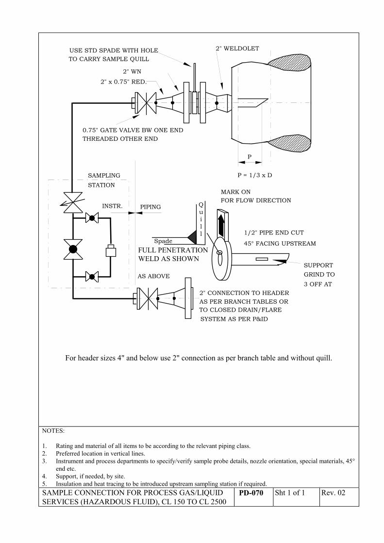
2" WELDOLET
2" WN
P
P = 1/3 x D
0.75" GATE VALVE BW ONE END
USE STD SPADE WITH HOLETO CARRY SAMPLE QUILL
2" x 0.75" RED.
���������������������������������������������������������������������������������������������������������������������������������������������������������������������������������������������������������
���������������������������������������������������������������������������������������������������������������������������������������������������������������������������������������������������������
THREADED OTHER END
SAMPLING
MARK ONFOR FLOW DIRECTION
1/2" PIPE END CUT
45° FACING UPSTREAM
AS ABOVE
2" CONNECTION TO HEADERAS PER BRANCH TABLES OR
PIPINGINSTR.
STATION
TO CLOSED DRAIN/FLARESYSTEM AS PER P&ID
SUPPORTGRIND TO3 OFF AT
FULL PENETRATIONWELD AS SHOWN
Quill
Spade
For header sizes 4" and below use 2" connection as per branch table and without quill.
NOTES:
1. Rating and material of all items to be according to the relevant piping class.2. Preferred location in vertical lines.3. Instrument and process departments to specify/verify sample probe details, nozzle orientation, special materials, 45°
end etc.4. Support, if needed, by site.5. Insulation and heat tracing to be introduced upstream sampling station if required.SAMPLE CONNECTION FOR PROCESS GAS/LIQUIDSERVICES (HAZARDOUS FLUID), CL 150 TO CL 2500
PD-070 Sht 1 of 1 Rev. 02
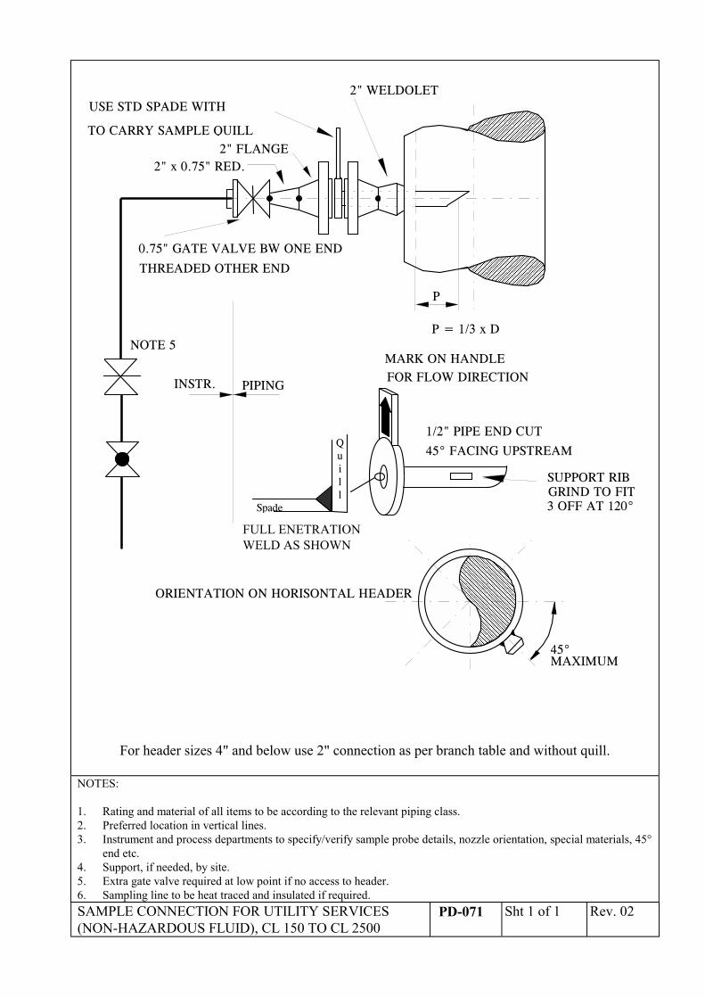
2" WELDOLET
2" FLANGE
P
P = 1/3 x D
0.75" GATE VALVE BW ONE END
USE STD SPADE WITH
TO CARRY SAMPLE QUILL
2" x 0.75" RED.
������������������������������������������������������������������������������������������������������������������������������������������������������������������������������������������������
������������������������������������������������������������������������������������������������������������������������������������������������������������������������������������������������THREADED OTHER END
MARK ON HANDLEFOR FLOW DIRECTION
1/2" PIPE END CUT
45° FACING UPSTREAM
PIPINGINSTR.
������������������������������������������������������������������������������������������������������������������������������������������������������������������������������������������������������������������������
45°MAXIMUM
ORIENTATION ON HORISONTAL HEADER
NOTE 5
������������
����������
SUPPORT RIBGRIND TO FIT3 OFF AT 120°
FULL ENETRATIONWELD AS SHOWN
Quill
Spade
For header sizes 4" and below use 2" connection as per branch table and without quill.
NOTES:
1. Rating and material of all items to be according to the relevant piping class.2. Preferred location in vertical lines.3. Instrument and process departments to specify/verify sample probe details, nozzle orientation, special materials, 45°
end etc.4. Support, if needed, by site.5. Extra gate valve required at low point if no access to header.6. Sampling line to be heat traced and insulated if required.SAMPLE CONNECTION FOR UTILITY SERVICES(NON-HAZARDOUS FLUID), CL 150 TO CL 2500
PD-071 Sht 1 of 1 Rev. 02
�������������������������
���������������������������������������������������������������
���������������������
G
F
E D
L
E NOTE 7
C
T
A B
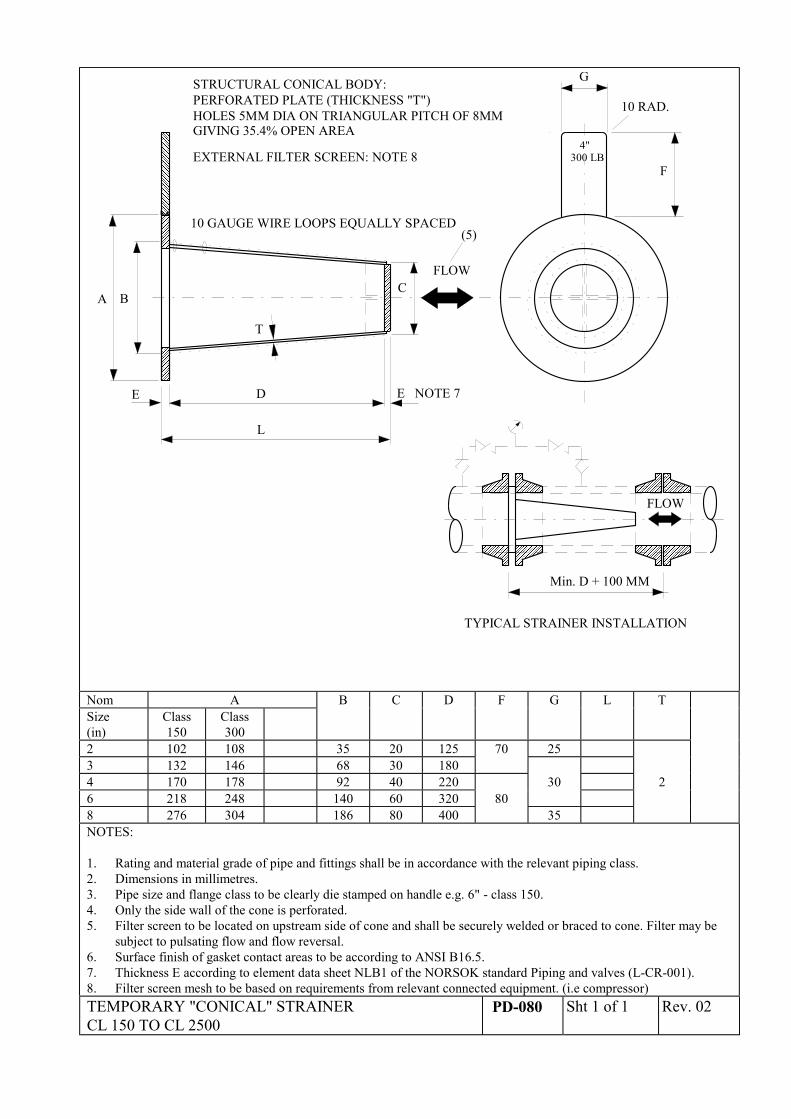
PERFORATED PLATE (THICKNESS "T")HOLES 5MM DIA ON TRIANGULAR PITCH OF 8MMGIVING 35.4% OPEN AREA
STRUCTURAL CONICAL BODY:
EXTERNAL FILTER SCREEN: NOTE 8
10 GAUGE WIRE LOOPS EQUALLY SPACED
FLOW
10 RAD.
4"300 LB
(5)
������������������������������������
������������������������
���������������������������������������
��������������������������
������������������������������������
������������������������
���������������������������������������������
������������������������������
Min. D + 100 MM
FLOW
����
TYPICAL STRAINER INSTALLATION
Nom A B C D F G L TSize(in)
Class150
Class300
2 102 108 35 20 125 70 253 132 146 68 30 1804 170 178 92 40 220 30 26 218 248 140 60 320 808 276 304 186 80 400 35NOTES:
1. Rating and material grade of pipe and fittings shall be in accordance with the relevant piping class.2. Dimensions in millimetres.3. Pipe size and flange class to be clearly die stamped on handle e.g. 6" - class 150.4. Only the side wall of the cone is perforated.5. Filter screen to be located on upstream side of cone and shall be securely welded or braced to cone. Filter may be
subject to pulsating flow and flow reversal.6. Surface finish of gasket contact areas to be according to ANSI B16.5.7. Thickness E according to element data sheet NLB1 of the NORSOK standard Piping and valves (L-CR-001).8. Filter screen mesh to be based on requirements from relevant connected equipment. (i.e compressor)TEMPORARY "CONICAL" STRAINERCL 150 TO CL 2500
PD-080 Sht 1 of 1 Rev. 02
��������
��������
����
������
������
����������������������������������������������������
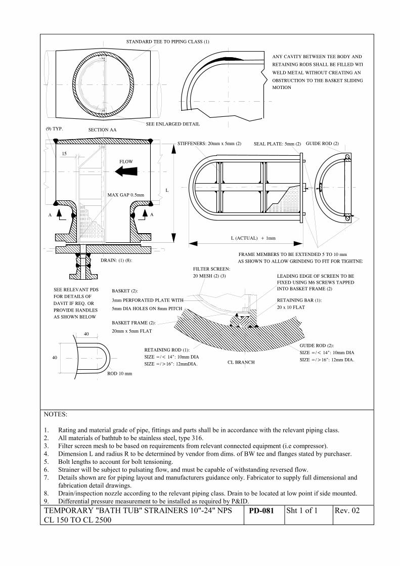
FIXED USING M6 SCREWS TAPPEDLEADING EDGE OF SCREEN TO BE
INTO BASKET FRAME (2)BASKET (2):
3mm PERFORATED PLATE WITH
5mm DIA HOLES ON 8mm PITCH
FILTER SCREEN:
20 MESH (2) (3)
RETAINING BAR (1):
20 x 10 FLAT
RETAINING ROD (1):
SIZE =/< 14": 10mm DIA
SIZE =/>16": 12mmDIA.
GUIDE ROD (2):
SIZE =/< 14": 10mm DIA
SIZE =/>16": 12mm DIA.��������������������������������������������
����
������
CL BRANCH
STIFFENERS: 20mm x 5mm (2) GUIDE ROD (2)SEAL PLATE: 5mm (2)
RETAINING RODS SHALL BE FILLED WIT
ANY CAVITY BETWEEN TEE BODY AND
WELD METAL WITHOUT CREATING AN
OBSTRUCTION TO THE BASKET SLIDING
MOTION
����
������
�
BASKET FRAME (2):
20mm x 5mm FLAT
L
SECTION AA
A A����
��������
L (ACTUAL) + 1mm
STANDARD TEE TO PIPING CLASS (1)
FLOW
15
SEE ENLARGED DETAIL
SEE RELEVANT PDSFOR DETAILS OF
DAVIT IF REQ. OR
DRAIN: (1) (8):
MAX GAP 0.5mm
(9) TYP.
FRAME MEMBERS TO BE EXTENDED 5 TO 10 mm
AS SHOWN TO ALLOW GRINDING TO FIT FOR TIGHTNES
PROVIDE HANDLESAS SHOWN BELOW
40
40
ROD 10 mm
NOTES:
1. Rating and material grade of pipe, fittings and parts shall be in accordance with the relevant piping class.2. All materials of bathtub to be stainless steel, type 316.3. Filter screen mesh to be based on requirements from relevant connected equipment (i.e compressor).4. Dimension L and radius R to be determined by vendor from dims. of BW tee and flanges stated by purchaser.5. Bolt lengths to account for bolt tensioning.6. Strainer will be subject to pulsating flow, and must be capable of withstanding reversed flow.7. Details shown are for piping layout and manufacturers guidance only. Fabricator to supply full dimensional and
fabrication detail drawings.8. Drain/inspection nozzle according to the relevant piping class. Drain to be located at low point if side mounted.9. Differential pressure measurement to be installed as required by P&ID.TEMPORARY "BATH TUB" STRAINERS 10"-24" NPSCL 150 TO CL 2500
PD-081 Sht 1 of 1 Rev. 02
90
��215
115
3/4"48 DIA.
3535 B
60��
���
���
150
50
22 DIA.
20 DIA.
10
300
A E F20
175
150
150
D
C
R =230
GREASE NIPPLE
10
SOLID BAR
����
���� �����
�������
���������� ��
���
�
��
����
����������������
����
���
��
��������
��
������
������
��
����
������
NOTE 4
���
130
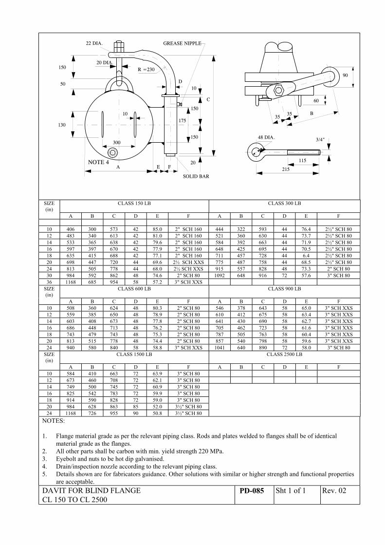
SIZE(in)
CLASS 150 LB CLASS 300 LB
A B C D E F A B C D E F
10 406 300 573 42 85.0 2" SCH 160 444 322 593 44 76.4 2½" SCH 8012 483 340 613 42 81.0 2" SCH 160 521 360 630 44 73.7 2½" SCH 8014 533 365 638 42 79.6 2" SCH 160 584 392 663 44 71.9 2½" SCH 8016 597 397 670 42 77.9 2" SCH 160 648 425 695 44 70.5 2½" SCH 8018 635 415 688 42 77.1 2" SCH 160 711 457 728 44 6.4 2½" SCH 8020 698 447 720 44 69.6 2½ SCH XXS 775 487 758 44 68.5 2½" SCH 8024 813 505 778 44 68.0 2½ SCH XXS 915 557 828 48 73.3 2" SCH 8030 984 592 862 48 74.6 2" SCH 80 1092 648 916 72 57.6 3" SCH 8036 1168 685 954 58 57.2 3" SCH XXS
SIZE(in)
CLASS 600 LB CLASS 900 LB
A B C D E F A B C D E F10 508 360 624 48 80.3 2" SCH 80 546 378 643 58 65.0 3" SCH XXS12 559 385 650 48 78.9 2" SCH 80 610 412 675 58 63.4 3" SCH XXS14 603 408 673 48 77.8 2" SCH 80 641 430 690 58 62.7 3" SCH XXS16 686 448 713 48 76.2 2" SCH 80 705 462 723 58 61.6 3" SCH XXS18 743 479 743 48 75.3 2" SCH 80 787 505 763 58 60.4 3" SCH XXS20 813 515 778 48 74.4 2" SCH 80 857 540 798 58 59.6 3" SCH XXS24 940 580 840 58 58.8 3" SCH XXS 1041 640 890 72 58.0 3" SCH 80
SIZE(in)
CLASS 1500 LB CLASS 2500 LB
A B C D E F A B C D E F10 584 410 663 72 63.9 3" SCH 8012 673 460 708 72 62.1 3" SCH 8014 749 500 745 72 60.9 3" SCH 8016 825 542 783 72 59.9 3" SCH 8018 914 590 828 72 59.0 3" SCH 8020 984 628 863 85 52.0 3½" SCH 8024 1168 726 955 90 50.8 3½" SCH 80
NOTES:
1. Flange material grade as per the relevant piping class. Rods and plates welded to flanges shall be of identicalmaterial grade as the flanges.
2. All other parts shall be carbon with min. yield strength 220 MPa.3. Eyebolt and nuts to be hot dip galvanised.4. Drain/inspection nozzle according to the relevant piping class.5. Details shown are for fabricators guidance. Other solutions with similar or higher strength and functional properties
are acceptable.DAVIT FOR BLIND FLANGECL 150 TO CL 2500
PD-085 Sht 1 of 1 Rev. 02
������������������������������
�
����
F
45°
G
2
1
E
50
50
O ROD
B DIA
A DIA ������
���
20.7
NOTE 6
15.6
NOTE 5
C
1 x 45°
1
1
FACESEE NOTE 4
WELDING NIPPLE
SEE DETAIL
��������������
��������������
15.6
NOTE 5
20.7
NOTE 6
35°
33.4
NOTE 6
26.7
NOTE 5
41 DIA 33.4 DIA
NOTE 5NOTE 6
45°
60°
40
90 ROUNDED
1" 3/4"
BELOW
GASKET CONTACT
FLANGE WNSCH. 160
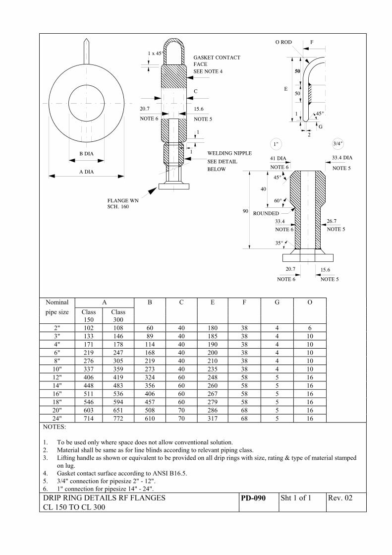
Nominal A B C E F G Opipe size Class Class
150 3002" 102 108 60 40 180 38 4 63" 133 146 89 40 185 38 4 104" 171 178 114 40 190 38 4 106" 219 247 168 40 200 38 4 108" 276 305 219 40 210 38 4 10
10" 337 359 273 40 235 38 4 1012" 406 419 324 60 248 58 5 1614" 448 483 356 60 260 58 5 1616" 511 536 406 60 267 58 5 1618" 546 594 457 60 279 58 5 1620" 603 651 508 70 286 68 5 1624" 714 772 610 70 317 68 5 16
NOTES:
1. To be used only where space does not allow conventional solution.2. Material shall be same as for line blinds according to relevant piping class.3. Lifting handle as shown or equivalent to be provided on all drip rings with size, rating & type of material stamped
on lug.4. Gasket contact surface according to ANSI B16.5.5. 3/4" connection for pipesize 2" - 12".6. 1" connection for pipesize 14" - 24".DRIP RING DETAILS RF FLANGESCL 150 TO CL 300
PD-090 Sht 1 of 1 Rev. 02
�������������������������������������������������������������������������������������������������������������������������������������������������������������������������������������������������������������������������������������������������������������
��������������������������������������������������������������������
������
���
���������
F
45°
G
2
1
E
50
50
O ROD
B D IA
A D IA
������������������������
��������������������
20 .7
N O TE 6
15 .6
N O TE 5
C
1 x 45°
1
1
FA C E
SE E N O T E 4
W E LD IN G N IPPLE
SE E D E T A IL �������������������������������������������������������������������������������������������������������������������������
��������������������������������������������������������������������������������������������������������������
15 .6
N O TE 5
20 .7
N O TE 6
35°
33 .4
N O TE 6
26 .7
N O TE 5
41 D IA 33.4 D IA
N O TE 5N O TE 6
45°
60°
40
90 RO UN D E D
1" 3/4"
BE LOW
G A SK E T C O NT A C T
FLA NG E W NSC H. 160
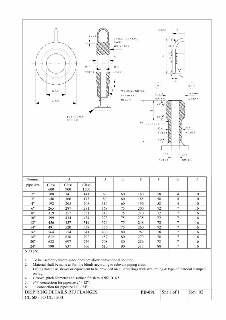
Nominal A B C E F G Opipe size Class Class Class
600 900 15002" 108 141 141 60 60 180 58 4 103" 146 166 173 89 60 185 58 4 104" 192 205 208 114 60 190 58 4 106" 265 287 281 168 75 200 72 7 168" 319 357 351 219 75 210 72 7 16
10" 399 434 434 273 75 235 72 7 1612" 456 457 519 324 75 248 72 7 1614" 491 520 579 356 75 260 72 7 1616" 564 574 641 406 80 267 78 7 1618" 612 638 702 457 80 279 78 7 1620" 682 697 756 508 80 286 78 7 1624" 790 837 900 610 90 317 88 7 16
NOTES:
1. To be used only where space does not allow conventional solution.2. Material shall be same as for line blinds according to relevant piping class.3. Lifting handle as shown or equivalent to be provided on all drip rings with size, rating & type of material stamped
on lug.4. Groove, pitch diameter and surface finish to ANSI B16.5.5. 3/4" connection for pipesize 2" - 12".6. 1" connection for pipesize 14" - 24".DRIP RING DETAILS RTJ FLANGESCL 600 TO CL 1500
PD-091 Sht 1 of 1 Rev. 02
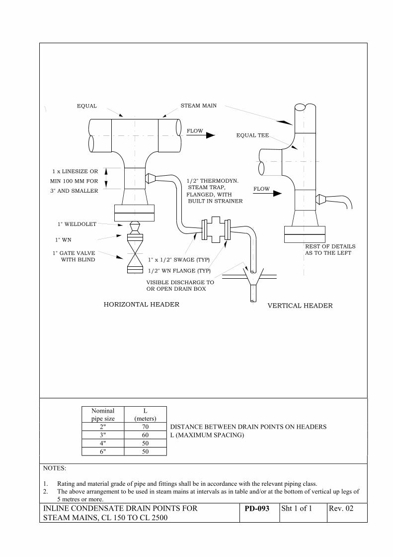
EQUAL STEAM MAIN
FLOW
1 x LINESIZE OR
MIN 100 MM FOR
3" AND SMALLER
HORIZONTAL HEADER
FLOW
VERTICAL HEADER
EQUAL TEE
1" GATE VALVEWITH BLIND
1" WN
1" WELDOLET
VISIBLE DISCHARGE TOOR OPEN DRAIN BOX
1" x 1/2" SWAGE (TYP)
1/2" WN FLANGE (TYP)
1/2" THERMODYN. STEAM TRAP,
REST OF DETAILSAS TO THE LEFT
FLANGED, WITH BUILT IN STRAINER
Nominalpipe size
L(meters)
2" 70 DISTANCE BETWEEN DRAIN POINTS ON HEADERS3" 60 L (MAXIMUM SPACING)4" 506" 50
NOTES:
1. Rating and material grade of pipe and fittings shall be in accordance with the relevant piping class.2. The above arrangement to be used in steam mains at intervals as in table and/or at the bottom of vertical up legs of
5 metres or more.INLINE CONDENSATE DRAIN POINTS FORSTEAM MAINS, CL 150 TO CL 2500
PD-093 Sht 1 of 1 Rev. 02
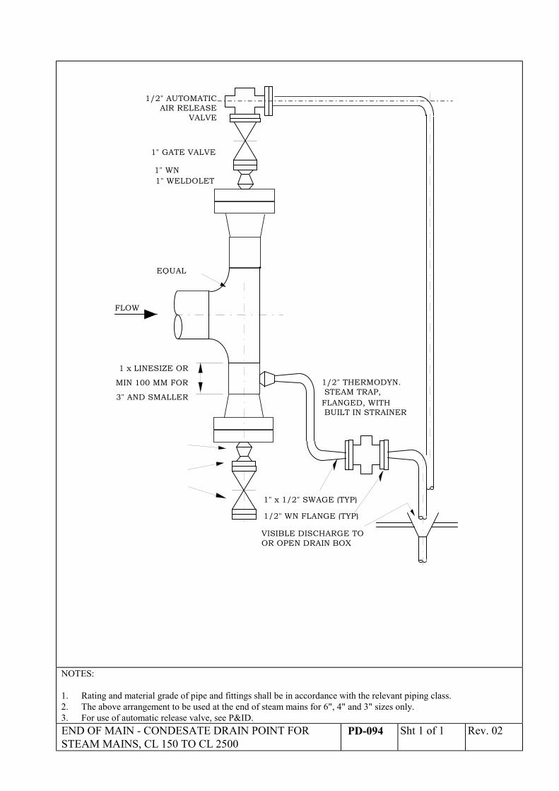
EQUAL
FLOW
1 x LINESIZE OR
MIN 100 MM FOR
3" AND SMALLER
1" GATE VALVE
1" WN1" WELDOLET
VISIBLE DISCHARGE TOOR OPEN DRAIN BOX
1" x 1/2" SWAGE (TYP)
1/2" WN FLANGE (TYP)
1/2" THERMODYN. STEAM TRAP,FLANGED, WITH BUILT IN STRAINER
1/2" AUTOMATICAIR RELEASE
VALVE
NOTES:
1. Rating and material grade of pipe and fittings shall be in accordance with the relevant piping class.2. The above arrangement to be used at the end of steam mains for 6", 4" and 3" sizes only.3. For use of automatic release valve, see P&ID.END OF MAIN - CONDESATE DRAIN POINT FORSTEAM MAINS, CL 150 TO CL 2500
PD-094 Sht 1 of 1 Rev. 02
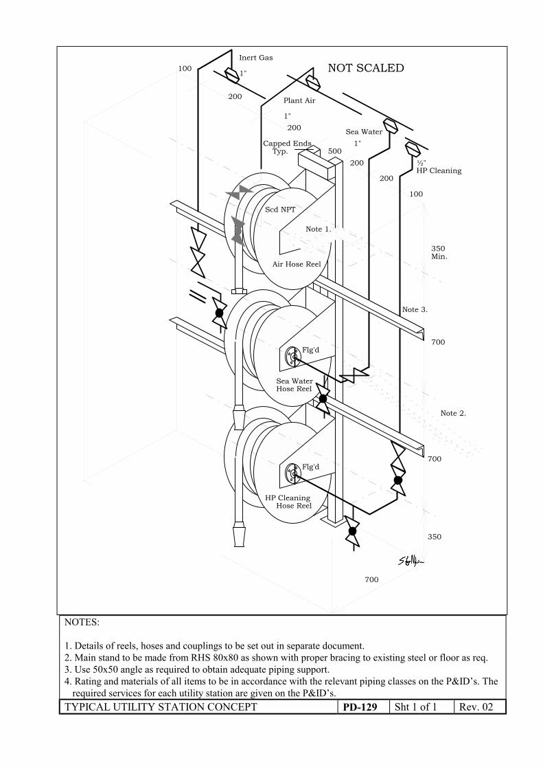
Note 1.
Sea WaterHose Reel
Flg'd
Flg'd
Air Hose Reel
Inert Gas
700
500
200
200
200
200
100
100
Plant Air
Sea Water
HP Cleaning
1"
1"
½"
Scd NPT
1"
NOT SCALED
Hose ReelHP Cleaning
350
700
700
350Min.
Capped EndsTyp.
Note 2.
Note 3.
NOTES:
1. Details of reels, hoses and couplings to be set out in separate document.2. Main stand to be made from RHS 80x80 as shown with proper bracing to existing steel or floor as req.3. Use 50x50 angle as required to obtain adequate piping support.4. Rating and materials of all items to be in accordance with the relevant piping classes on the P&ID’s. The
required services for each utility station are given on the P&ID’s.TYPICAL UTILITY STATION CONCEPT PD-129 Sht 1 of 1 Rev. 02