NORRISEAL CONTROLS - Sky Eye...
21
NORRISEAL CONTROLS MANUFACTURED IN CANADA BY ALBERTA OIL TOOL LEVEL CONTROLLERS SERIES 1001A and 1001XL
Transcript of NORRISEAL CONTROLS - Sky Eye...

NORRISEALCONTROLS
MANUFACTURED IN CANADA BY ALBERTA OIL TOOL
LEVEL CONTROLLERSSERIES 1001A and 1001XL
Operation and Maintenance
Series 1001A and 1001XL Liquid Level Controllers
Maintained by: Sales Department Page 2 of 21 Doc. Name: OpMain1001.docApproved by: Quality Department Rev.: C Date: 23-Jun-03
CONTENTS
Introduction
Model Identification 3
Specifications
Performance Characteristics 4
Material 5
Configuration 5
Installation and Start-Up
Configuration 6
Start-Up 9
Operation
Principle of Operation 10
Snap Pilot 11
Relief Pilot 11
Throttle Pilot 11
Electric Pilot Switches
Explosion Proof Enclosure 12
Control Adjustments
Level 13
Sensitivity 13
Liquid Interface 13
Case Mounting and Action Conversions
Pilot Action 13
Case Mounting 14
Dimensions 15
Maintenance
Preventive Maintenance 16
Basic Electric Switch 16
Troubleshooting 17
Parts List 18

Operation and Maintenance
Series 1001A and 1001XL Liquid Level Controllers
Maintained by: Sales Department Page 3 of 21 Doc. Name: OpMain1001.docApproved by: Quality Department Rev.: C Date: 23-Jun-03
INTRODUCTION – MODEL DESIGNATION
2 SM 60 - S R D L - A G
END CONNECTIONS ENCLOSURESIZE CODE2.00” 2
CODE TYPE
2.50” 5 B Sealed Case/Cover Only3.00” 3 C Sealed Case/Cover and Piped Exhaust4.00” 46.00” 6
D Sealed Case/Cover, Piped Exhaust and Special MarineInternals
E Sealed Case/Cover and Special Marine Internals
G Sealed Case/Cover Only (Lever Latch)1001A & 1001XL
END CONNECTIONSTYPE CODE
H Sealed Case/Cover and Piped Exhaust (Lever Latch)1001A & 1001XL
Beveled Slip On SCRaised Face RF J Sealed Case Cover and Piped Exhaust, and Special
Marine Service (Lever Latch) 1001A & 1001XLFlanged Ring Type Joint RJScrewed Ma le NPT SM
K Sealed Case/Cover and Special Marine Service(Lever Latch) 1001A & 1001XL
SERVICE CONDITIONCODE SERVICE
A Standard/Standard GaugesB Vibration/Standard Gauges
PRESSURE RATING C Vibration/Vibration GaugesANSI RATING* CODE D Vibration/Liquid Filled Gauges150 285 02300 740 07400 960 09
1000 10 DESCRIPTION UNIT TYPE CODE600 1480 14
1500 15Pressure GaugesBronze 0 to 30 psi
1001A& 1001XL -
2000 20900 2220 21
Pressure GaugesBronze 0 to 60 psi
1001A& 1001XL H
2500 253000 30
Pressure Gauges316 SST 0 to 30 psi
1001A& 1001XL
J
1500 3705 364000 40
Pressure Gauges316 SST 0 to 60 psi
1001A & 1001XL K
5000 506000 60
2500 6170 60SEAL/BEARING - MATERIAL*Body Pressure Rating subject to selection of displacer.
See Displacer Chart CODE O-RING BEARING TEMP.**E EPR 303 SST 275F VITON 316 SST 400L BUNA 303 SST 180
MATERIAL – BODY/SHAFT/BLOCK S AFLAS 316 SST 400BODY SHAFT/BEARING BEARING BLOCK CODE V VITON DELRIN 180
A696 CS or WCC 303 303 ---A696 CS (NACE) 316 316 N
** Seal temperature rating subject to selection of displacer.See Displacer Chart
316 (NACE) 316 316 R316 316 316 S
PILOT ACTIONCODE ACTION TYPE
D Direct ActingR Reverse Acting
PILOT MODEMODE TYPE CODE
Electric DPDT (X-Proof) DElectric SPDT (X-Proof) E MOUNTING CASEPneumatic Relief (w/60 PSIG Gauge) G CODE MOUNTING TYPEElectric SPDT (Hermetic Sealed) K B BackElectric DPDT (Hermetic Sealed) L L Left HandPneumatic Snap (On/Off) S R Right HandPneumatic Throttle (Modulating) T
DISPLACER TEMPERATURE/PRESSURE RATINGSDISPLACER CHART
MATERIAL PVC ACRYLIC ALUMINUM SST-0 SST-2MAX. TEMP (oF) 140 200 400 400 400MAX. PRESSURE (PSIG) 6,170 6,170 6,170 720 2,000
Operation and Maintenance
Series 1001A and 1001XL Liquid Level Controllers
Maintained by: Sales Department Page 4 of 21 Doc. Name: OpMain1001.docApproved by: Quality Department Rev.: C Date: 23-Jun-03
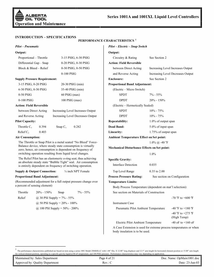
INTRODUCTION – SPECIFICATIONSPERFORMANCE CHARACTERISTICS 1
Pilot – Pneumatic Pilot – Electric – Snap Switch
Output: Output:
Proportional – Throttle 3-15 PSIG, 6-30 PSIG Circuitry & Rating See Section 2
Differential Gap – Snap 0-20 PSIG, 0-30 PSIG Action: Field Reversible
Block & Bleed – Relief 0-30 PSIG, 0-50 PSIG between Direct Acting Increasing Level Increases Output
0-100 PSIG and Reverse Acting Increasing Level Decreases Output
Supply Pressure Requirement: Enclosure: See Section 2
3-15 PSIG, 0-20 PSIG 20-30 PSIG (min) Proportional Band Adjustment:
6-30 PSIG, 0-30 PSIG 35-40 PSIG (min) (Electric – Micro Switch)
0-50 PSIG 60 PSIG (max) SPDT 7% - 55%
0-100 PSIG 100 PSIG (max) DPDT 20% - 150%
Action: Field Reversible (Electric – Hermetically Sealed)
between Direct Acting Increasing Level Increases Output SPDT 10% - 75%
and Reverse Acting Increasing Level Decreases Output DPDT 10% - 75%
Pilot Capacity: Repeatability: 1.0% of output span
Throttle Cv 0.394 Snap Cv 0.282 Dead Band: 5.0% of input span
Relief Cv 0.403 Linearity: 1.75% of output span
Air Consumption: Ambient Temperature Effect on Set point:
1.0% @ -40 oF
Mechanical Disturbance Effects on Set point:
1.0%
Specific Gravity:
The Throttle or Snap Pilot is a metal seated “No Bleed” Force-Balance device, where steady state consumption is virtually zero; hence, air consumption is dependent on frequency of switching operation resulting from liquid level changes.The Relief Pilot has an elastomeric o-ring seat; thus achieving an absolute steady state “Bubble Tight” seal. Air consumption is entirely dependent on frequency of switching operation. Interface Detection 0.035
Supply & Output Connection: ¼ inch NPT Female Top Level Range 0.35 to 2.00
Proportional Band Adjustment: Process Pressure Rating: See section on Configuration
Temperature Limits:(Recommended adjustment for a full output pressure change over a percent of sensing element) Body Process Temperature (dependent on mat’l selection):
Throttle 20% - 150% Snap 7% - 55% See section on Materials of Construction
Relief @ 30 PSI Supply = 7% - 55% -70 oF to +600 oF
@ 50 PSI Supply = 20% - 100% Instrument Case
@ 100 PSI Supply = 50% - 200% Pneumatic Pilot Ambient Temperature -40 oF to +180 oF-40 oF to +275 oF(High Temp)
Electric Pilot Ambient Temperature -40 oF to +160 oFA Case Extension is used for extreme process temperatures or when body insulation is to be used.
1The performance characteristics published are based on tests using a series 1001 Model 2SM60LLC with 1.88” Dia. X 12.00” long displacer and 12.5” arm length for horizontal element position or 15.00” arm length
for vertical element position, operating in a specific gravity liquid at 80 oF temperature, and 100 PSIG pressure. Performance characteristics may vary depending on application.

Operation and Maintenance
Series 1001A and 1001XL Liquid Level Controllers
Maintained by: Sales Department Page 5 of 21 Doc. Name: OpMain1001.docApproved by: Quality Department Rev.: C Date: 23-Jun-03
INTRODUCTION – SPECIFICATIONSMATERIALS OF CONSTRUCTION
Body: LLC Torque Bar: Aluminum (Std.)1001A ASTM A696/A105 (-20 oF to +600 oF) Flapper Bar: 303 SST
ASTM A276/A182 (-70 oF to +600 oF) Spring Adjusting Knot: Aluminum (Std.)1001XL ASTM A216 WCC/A105 (-20 oF to +600 oF) Fulcrum: Nylon w/ Zinc Screw (Std.)
ASTM A351 CF8M/A182 (-70 oF +600 oF) Balancing Spring: Light – SST w/ Green Marking
Displacers: PVC (-20 oF to +140 oF) Medium – SST w/ No MarkingAcrylic (-20 oF to +200 oF) Heavy – SST w/ Yellow Marking
NACE Service 316 SST (-20 oF to +400 oF) Extra Heavy – SST w/ Red Marking
Displacer Arm: 316 SST (Std.) CONFIGURATIONVertical Hanger (swivel for vertical displacer position): Body End Connections:
316 SST (Std.) Sizes (Pipe) 1.5” to 8.0”
Chain (for vertical extension and/or split displacer) Beveled – Butt Weld To 6000 PSIG304 SST Threaded (NPT) To 6000 PSIG
Shaft: 316 SST (-70 oF to +600 oF) Flanged (RF & RT) 150 thru 2500 ANSI Class
Case Mounting –1001A:Bearing Blocks: 316 SST (Std.) (-70 oF to +600 oF) Right Hand Where the body process connection is to the right
Bearings: TFE Sealed 440 C SST of the case.(-70 oF to +600 oF) Left Hand Where the body process connection is to the left
of the case.
Shaft Seals: Nitrile (-50 oF to +180 oF) Displacer Positions: Horizontal, Vertical, Split, Link,Nitrile Lo-Temp (-70 oF to +180 oF) HV (Horizontal/Vertical),Fluorocarbon (-20 oF to +400 oF) TV (Hinged – Tilt Under)Aflas (-20 oF to +600 oF) Displacer Size (Diameter x Length in inches):EPR (-70 oF to +250 oF) Selection is dependent on sizing for media application
Case & Cover: Die Cast Anodized Aluminum, with Diameter Range 1.00” thru 4.00”Enamel Paint Length Range 3.00” thru 32.00”
Pilot: Diameter x Length combinations are limited within controller construction.Body Displacer Arms Length (inches): 7.75” thru 30.00”
Throttle Aluminum w/ Aluminum Seat Balancing SpringRelief Aluminum w/ Elastomer Seat Four Ranges. Color coded dependent on arm length and displacer size.Snap Aluminum Seat Light Duty (Green) Medium Duty (None)Snap-Vibration Service Aluminum w/ Plastic Seat Heavy Duty (Yellow) Extra Heavy Duty (Red)Gasket Diaphragm Nitrile (Std.), Fluorocarbon (Opt.)
Filter Element 40 micron Phenolic Resin Impregnate FeltScrews & Nuts SST
Supply & Output Gauges: Brass (Std.), 316 SST (Opt.)Brass Liquid Filled (Opt.)316 SST Liquid Filled (Opt.)
Operation and Maintenance
Series 1001A and 1001XL Liquid Level Controllers
Maintained by: Sales Department Page 6 of 21 Doc. Name: OpMain1001.docApproved by: Quality Department Rev.: C Date: 23-Jun-03
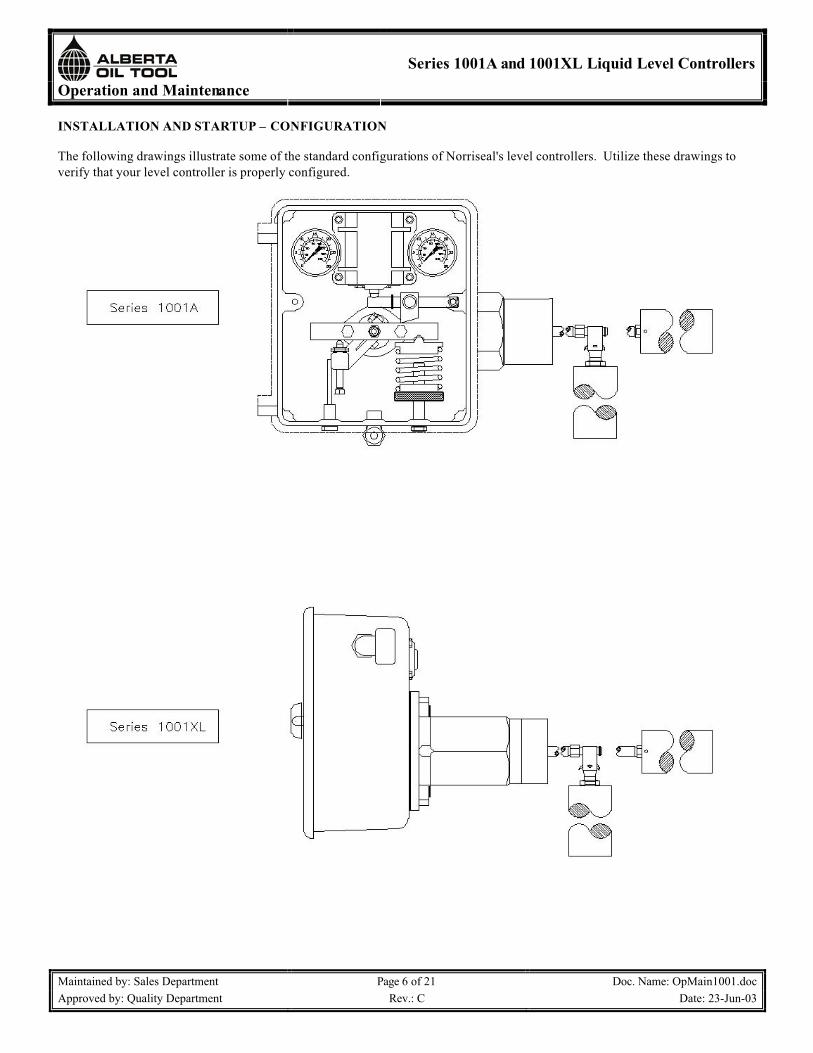
INSTALLATION AND STARTUP – CONFIGURATION
The following drawings illustrate some of the standard configurations of Norriseal's level controllers. Utilize these drawings to verify that your level controller is properly configured.

Operation and Maintenance
Series 1001A and 1001XL Liquid Level Controllers
Maintained by: Sales Department Page 7 of 21 Doc. Name: OpMain1001.docApproved by: Quality Department Rev.: C Date: 23-Jun-03
INSTALLATION AND STARTUP – CONFIGURATION (continued)
The following drawings illustrate some of the standard configurations of Norriseal’s level controllers. Utilize these drawings to verify that your level controller is properly configured.
Series 1001AWith horizontal chamber
Series 1001AMounted to vertical chamber
Operation and Maintenance
Series 1001A and 1001XL Liquid Level Controllers
Maintained by: Sales Department Page 8 of 21 Doc. Name: OpMain1001.docApproved by: Quality Department Rev.: C Date: 23-Jun-03
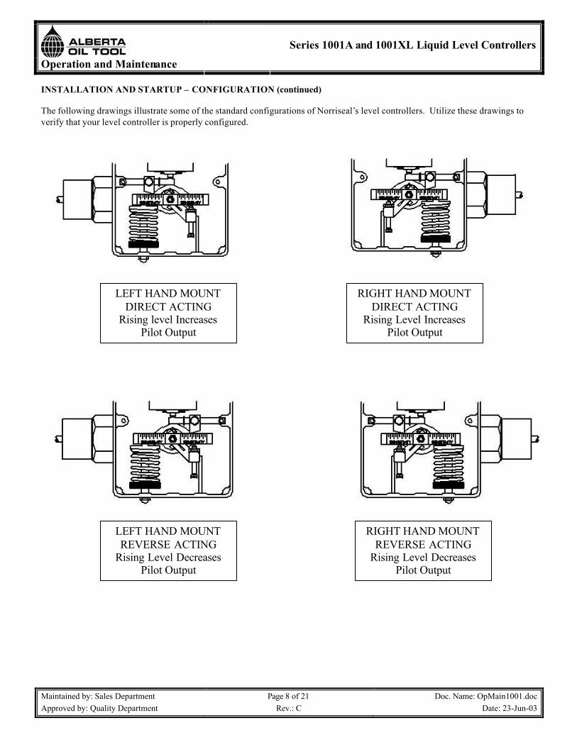
INSTALLATION AND STARTUP – CONFIGURATION (continued)
The following drawings illustrate some of the standard configurations of Norriseal’s level controllers. Utilize these drawings to verify that your level controller is properly configured.
LEFT HAND MOUNT REVERSE ACTING
Rising Level Decreases Pilot Output
LEFT HAND MOUNT DIRECT ACTING
Rising level Increases Pilot Output
RIGHT HAND MOUNT DIRECT ACTING
Rising Level Increases Pilot Output
RIGHT HAND MOUNT REVERSE ACTING
Rising Level Decreases Pilot Output

Operation and Maintenance
Series 1001A and 1001XL Liquid Level Controllers
Maintained by: Sales Department Page 9 of 21 Doc. Name: OpMain1001.docApproved by: Quality Department Rev.: C Date: 23-Jun-03
INSTALLATION AND STARTUP – STARTUP
Norriseal level controllers are normally shipped in threepieces. Therefore, some assembly is required. Thefollowing sections will lead you through assembly andrecommended start-up procedure.
Assembly Steps:1. Screw displacer arm into controller body.2. Screw displacer onto displacer arm.
Arm Adjustment:Rock Torque Bar by hand to verify Arm is NOT restingagainst vessel nozzle. (Arm must be reasonably centered in connection opening). Turn Adjusting Knob under Balance Spring to position Arm.
To Lower Level:Turn Adjusting Knob CLOCKWISE to increasecompression on Balance Spring.
To Raise Level:Turn Adjusting Knob COUNTERCLOCKWISE todecrease compression on Balance Spring.
To Adjust Proportional Band (Span):Loosen Screw in Sensitivity Fulcrum and slide Fulcrum along Flapper Bar. To DECREASE Proportional Band (INCREASES SENSITIVITY) slide Fulcrum towardSnap Ring. To INCREASE Proportional Band(DECREASES SENSITIVITY) slide Fulcrum awayfrom Snap Ring.

Operation and Maintenance
Series 1001A and 1001XL Liquid Level Controllers
Maintained by: Sales Department Page 10 of 21 Doc. Name: OpMain1001.docApproved by: Quality Department Rev.: C Date: 23-Jun-03
OPERATION – PRINCIPLE OF OPERATION
Principle of OperationA spring balances the weight of a displacement type sensing element. As liquid rises around the displacer, the amount of force made available to the pilot is proportional to the volume of liquid displaced by the displacer.The higher the liquid level, the greater the force available to the pilot thrust pin. This direct-acting force is easily reversed in the field.The force available is transmitted to the pilot thrust pin through a lever and fulcrum. The control is direct acting (rising level increases pilot output) when the pivot point of the lever is on the spring side of the control case.The control is reverse acting when the pivot point is on the opposite side of the control case from the spring (rising level decreases pilot output).
Adjusting Proportional Band:Moving the fulcrum closer to the pivot point increases the proportional band*; moving the fulcrum toward the snap ring decreases the proportional band. A 3-15 psi or 6-30 psi output signal may be obtained over any portion of thedisplacer by adjusting the fulcrum as described.
• Proportional band is the ratio of used displacerlength to total length of displacer. Example: If six inches of level change will develop a 3-15 psioutput signal with a 12" long vertical displacer, the level controller is said to have a 50% proportional band.
Top Level Control:With spring force heldconstant, the higher theliquid level on the displacer,the greater becomes theforce available to the pilot.When spring force isreduced (by decompressing the spring), a higher level on the displacer is required to produce the same force as before.
Liquid Interface Control:Spring compression can be reduced to a further position where a hydrocarbon liquid level will rise above thedisplacer.This wide spring rangemakes the control of aliquid interface possiblewith the standard displacer.The adjustment is usuallymade as the lighter liquid rises on the displacer.After the spring is adjusted so the lighter liquid will not operate the control, there is adequate spring force inreserve to enabledisplacement of the heavier liquid to actuate the pilot.

Operation and Maintenance
Series 1001A and 1001XL Liquid Level Controllers
Maintained by: Sales Department Page 11 of 21 Doc. Name: OpMain1001.docApproved by: Quality Department Rev.: C Date: 23-Jun-03
OPERATION – PRINCIPLE OF OPERATION, SNAP PILOT, RELIEF PILOT AND THROTTLE PILOT
Snap PilotThe snap pilot is comprised of two metal seated valves -one at "D" to admit pilot supply pressure, and one at "C" to exhaust pressure.Ball "A" controls the flow of instrument air into the pilot at seat "D" and is heldclosed with force exerted by supply pressure on theseating area of the ball.When the upwardmechanical force transmitted to thrust pin "B" is sufficient to overcome the forceholding ball "A" seated, "A"snaps upward allowinginstrument air to flow past "A" and to the output port "H" of the pilot.The spherical end of thrust pin "B" closes the exhaust port at "C" the instant ball "A" snaps upward. The exhaust port seating area is smaller than the seating area of the supply port; therefore, the push rod must remain seated against supply pressure until force on the thrust pin "B" diminishes.As the force acting on thrust pin "B" is reduced the supply pressure acting downward on ball "A" overcomes theupward force at thrust pin "B" and reversing action occurs.ball "A" closes the supply pressure at valve "D" andsimultaneously opens the exhaust port at valve "C"; thus venting gas from port "H". The Snap Action results from the differences in seating areas of the two internal pilot valves.
Relief PilotThe relief pilot used in Block & Bleed systems operatesidentically to the snap pilot,except with two differences.Seat "D" has an added resilient seat "F" and flow passage at "G" is enlarged. The seat seal "F" is an elastromeric o-ring whichgives air absolute "zero leakage" seal of the supply pressure at ball "A". Just as in the snap pilot, when mechanical force transmitted through thrust pin"B" exceeds the downward force of the supply pressure at seat"D", ball "A" snaps upwardallowing instrument air to flow past ball "A" and to port "H".
The flow passage at "G" has a 43% larger flow capacity than the snap pilot; thus permitting instrument supply air to vent at a faster rate. The pilot valves will reset when mechanical force is reduced.The relief pilot cannot be converted into snap or throttle application.
Throttling PilotThe throttle pilot, used formodulating control, also utilizestwo internal valves ("D" and "C") to admit and exhaust air pressure.A diaphragm "E" used inconjunction with the valve at "C" creates a chamber for sensingpressure/force feedback.When a mechanical force pushes upward on thrust rod at "B", the valve at "C" is closed andsimultaneously opens valve "D"allowing instrument air to flowinto the chamber above diaphragm "E" and to output "H". The air continues flowing until theincreasing pressure builds afeedback force on diaphragm "E" that pushes downward equalizing the upward force applied to thrust rod "B". These balanced forces are the reason to the term "Force Balance."The throttle pilot works in the same manner as the snap pilot except the output pressure is proportional the mechanical force applied at push rod "B". As the push rod forcechanges, the pilot seeks to maintain equilibrium by either decreasing (exhausting) output loading pressure at valve "C" or increasing output loading pressure at valve "D".Instrument air does not flow when the loading pressures of the pilot are balanced.

Operation and Maintenance
Series 1001A and 1001XL Liquid Level Controllers
Maintained by: Sales Department Page 12 of 21 Doc. Name: OpMain1001.docApproved by: Quality Department Rev.: C Date: 23-Jun-03
CODE CIRCUITRY ELECTRICAL RATING
UL and CSA Listed:
15 amps, 125, 250 or 480 VAC
1/8 hp, 125 VAC; 1/4 hp, 250 VAC;
“E” EX-Qor
“O” OP-Q
Single – PoleDouble – Throw
A
1/2 amp, 125 VDC; 1/4 amp, 250 VDC
UL and CSA Listed:
10 amps, 125 or 250 VAC
.3 amp, 125 VDC; .125 amp, 250 VDC
“D” EXD-Qor
“F” OPD-Q
Double – PoleDouble – Throw
B
HERMETICALLY SEALED PILOT
“K”Hermetic
030
Single – PoleDouble - Throw
11 amps, 1/4 hp @ 125/250 VAC;
5 amps Res @ 28 VDC;
0.5 amps @ 125 VDC
“L”Hermetic
057
Double – PoleDouble - Throw
OPERATION – ELECTRIC PILOT SWITCHESEXPLOSION-PROOF AND SPLASH PROOF ENCLOSURES
Electric Pilot SwitchesTwo standard switches are available, single pole double throw (SPDT) or double pole double throw (DPDT).
“EX” Explosion-Proof EnclosureFlame paths within the housings of these switches cool exploding gases below the kindling temperature before they reach explosive gases surrounding the housing.The enclosed replaceable basic switch is accessible when the cover plate is removed. “EX” explosion-proof switches are
not sealed and therefore are not recommended for use in areas where they will be subjected to liquid splash.Micro Switch "EX" switches are listed by Underwriter's Laboratories and CSA for use in hazardous locations Class 1, Groups C and D, and Class 2, Groups E, F and G. This includes vapors of ethyl ether, gasoline, petroleum, alcohol, acetone, lacquer solvent, natural gas and atmosphere charged with grain dust, metal dust, carbon black, and coal or coke dust. Switch listed for Class 1, Group B (hydrogenatmosphere) is available. EX switches also meet NEMA 1 enclosure requirements. CSA requires the followingstatement for Class 1, Group B:
CAUTION:To prevent the emission of hot particles, joint surfaces must be thoroughly cleaned before closing cover.
ATTENTION:Pout empecher la projection de particles chaudes, les joints du couvercle doivent etre nettoyes a fond avant de fermer le couvercle.
Hermetically Sealed Enclosure for Hazardous LocationsThese switch leads are terminated in a junction box UL listed Class 1, Groups C and D, Class 2, Groups E, F and G.The switches are hermetically sealed for hazardous locations listed UL and CSA Class 1, Groups A, B, C and D; Class 2,Groups E, F and G.
Green - Ground
Blue – N.O.1Red – N.C.1Black – Com1
Blue – N.O.2Red – N.C.2Black – Com2
Green - Ground
Blue – N.O.1
Red – N.C.1
Purple – N.O.2Black – N.C.2Yellow – Com2
Brown – Com1
Red – N.C.
Blue – N.O.
Green - Ground
Operation and Maintenance
Series 1001A and 1001XL Liquid Level Controllers
Maintained by: Sales Department Page 13 of 21 Doc. Name: OpMain1001.docApproved by: Quality Department Rev.: C Date: 23-Jun-03
OPERATION – CONTROL ADJUSTMENTS, CASE MOUNTING AND ACTION CONVERSIONS
CONTROL ADJUSTMENTS– LEVEL, SENSITIVITY & LIQUID INTERFACE
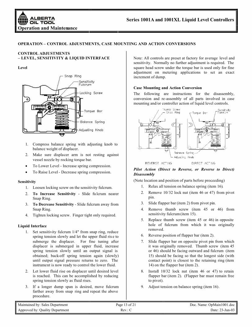
Level
1. Compress balance spring with adjusting knob to balance weight of displacer.
2. Make sure displacer arm is not resting againstvessel nozzle by rocking torque bar.
• To Lower Level - Increase spring compression.• To Raise Level - Decrease spring compression.
Sensitivity1. Loosen locking screw on the sensitivity fulcrum.2. To Increase Sensitivity - Slide fu lcrum nearer
Snap Ring.3. To Decrease Sensitivity - Slide fulcrum away from
Snap Ring.4. Tighten locking screw. Finger tight only required.
Liquid Interface1. Set sensitivity fulcrum 1/4" from snap ring, reduce
spring tension slowly and let the upper fluid ris e to submerge the displacer. For fine tuning afterdisplacer is submerged in upper fluid, increasespring tension slowly until an output signal is obtained; back-off spring tension again (slowly)until output signal pressure returns to zero. The instrument is now ready to control the lower fluid.
2. Let lower fluid rise on displacer until desired level is reached. This can be accomplished by reducing spring tension slowly as fluid rises.
3. If a longer dump span is desired, move fulcrumfarther away from snap ring and repeat the above procedure.
Note: All controls are preset at factory for average level andsensitivity. Normally no further adjustment is required. The square head screw under the torque bar is used only for fine adjustment on metering applications to set an exactincrement of dump.
Case Mounting and Action ConversionThe following are instructions for the disassembly,conversion and re-assembly of all parts involved in casemounting and/or controller action of liquid level controls.
Pilot Action (Direct to Reverse, or Reverse to Direct)Disassembly(Note location and position of parts before proceeding)
1. Relax all tension on balance spring (item 16).2. Remove 10/32 lock nut (item 46 or 47) from pivot
pin.3. Slide flapper bar (item 2) from pivot pin.4. Remove thumb screw (item 45 or 46) from
sensitivity fulcrum (item 15).5. Replace thumb screw (item 45 or 46) in opposite
hole of fulcrum from which it was originallyremoved.
6. Reverse position of flapper bar (item 2).7. Slide flapper bar on opposite pivot pin from which
it was originally removed. Thumb screw (item 45 or 46) should be facing outward and fulcrum (item15) should be facing so that the longest side (with contact point) is closest to the retaining ring (item 14) on the flapper bar (item 2).
8. Install 10/32 lock nut (item 46 or 47) to retain flapper bar (item 2). (Flapper bar must remain free to pivot).
9. Adjust tension on balance spring (item 16).

Operation and Maintenance
Series 1001A and 1001XL Liquid Level Controllers
Maintained by: Sales Department Page 14 of 21 Doc. Name: OpMain1001.docApproved by: Quality Department Rev.: C Date: 23-Jun-03
OPERATION – CONTROL ADJUSTMENTS, CASE MOUNTING AND ACTION CONVERSIONS (continued)
Procedure for Case Mounting ConversionDisassembly(Note location and position of parts before proceeding)
1. Relax all tension on balance spring (item 16).2. Remove balance spring (item 16) and upper spring
retainer (item 24) from pilot case (item 1).3. Remove 3/8-24 x 1.75" cap screw (item 51 or 52)
and lower spring retainer (item 33) from case (item 1).
4. Remove 2, 10/32 lock nuts (item 46 or 47). (Use 7/16 wrench.)a. One nut on end of shaft (item 32).b. One nut on pivot pin retaining flapper bar (item
2).5. Slide flapper bar (item 2) from pivot pin.6. Slide torque bar (item 36) from shaft (item 32).7. Loosen 2, 1/4" hex head cap screws (items 42 or
44) in level adjusting bar (item 17). (Use 1/2 box-end wrench).a. Holding level adjusting bar (item 17), loosen
both screws until level adjusting bar (item 17)is free on shaft (item 32).
b. Slide level adjusting bar (item 17) from shaft(item 32).
c. Slide spacer (item 26) from shaft (item 32).8. Remove 2, 1/4-28 x 3/8" hex head cap screws (item
41 or 45) so that pilot case (item 1) is loose. (Use 1/2 socket wrench.)
9. Remove case (item 1) from level control body (item 54 or 55).
Conversion and Re-Assembly(See drawings for desired mounting location.)
1. Install 2, 1/4-28 x 3/8" hex head cap screws (item 41 or 45) into case mounting holes.a. Mount case (item 1) to body (item 54 or 55)
with 2 screws.b. Tighten screws. (Torque to 6 ft. lbs.)
2. Slide spacer (item 26) on the shaft (item 32).3. Level Adjusting Bar (item 17).
a. Position level adjusting screw (item 35) so that there is equal amount of thread showing above and below bar.
b. Slide level adjusting bar (item 17) on shaft(item 32) against spacer (item 26).
c. Snug up 2, 1/4-28 x 3/8" hex head cap screws(item 41 or 45) in bar. (Do not tighten.)
d. Slide torque bar (item 36) on shaft (item 32)temporarily for positioning of level adjusting bar (item 17).
e. Position level adjusting bar (item 17) so that torque bar is parallel with displacer arm (item 23) when the round tip of level adjusting screw(item 52) is touching the torque bar (item 36).
f. With level adjusting bar (item 17) positioned -slide torque bar (item 36) from shaft andtighten 2, 1/4-28 x 3/8" hex head cap screws(items 41 or 45). Tighten screw nearest theslotted end of the level adjusting bar first.(Torque to 6 ft.lbs.)
4. Slide torque bar (item 36) onto shaft (item 32) with countersunk hole for spring retainer (item 24)facing down.a. Left Hand Mount - Hole is on the left side.b. Right Hand Mount - Hole is on the right side.
Operation and Maintenance
Series 1001A and 1001XL Liquid Level Controllers
Maintained by: Sales Department Page 15 of 21 Doc. Name: OpMain1001.docApproved by: Quality Department Rev.: C Date: 23-Jun-03
OPERATION – CONTROL ADJUSTMENTS, CASE MOUNTING AND ACTION CONVERSIONS (continued)
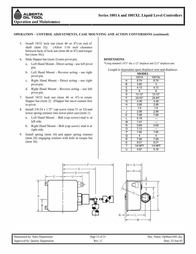
5. Install 10/32 lock nut (item 46 or 47) on end of shaft (item 32). (Allow 1/16 inch clearancebetween back of lock nut (item 46 or 47) and torque bar (item 36).)
6. Slide flapper bar (item 2) onto pivot pin.a. Left Hand Mount - Direct acting - use left pivot
pin.b. Left Hand Mount - Reverse acting - use right
pivot pin.c. Right Hand Mount - Direct acting - use right
pivot pin.d. Right Hand Mount - Reverse acting - use left
pivot pin.7. Install 10/32 lock nut (item 46 or 47) to retain
flapper bar (item 2). (Flapper bar mu st remain free to pivot.
8. Install 3/8-24 x 1.75” cap screw (item 51 or 52) and lower spring retainer into lower pilot case (item 1).a. Left Hand Mount – Bolt (cap screw) stud is at
left side.b. Right Hand Mount - Bolt (cap screw) stud is at
right side.9. Install spring (item 16) and upper spring retainer
(item 24) engaging retainer with hole in torque bar(item 36).
DIMENSIONS*Using standard 1.875” dia. x 12” displacer and 12.5” displacer arm.
Length is dependant upon displacer arm and displacer.MODEL
1001A 1001XLA 8.74 8.74B 3.85 3C 4.13 4.13D 6 6E 13.12* 13.12*F 24.43* 24.44*G 4.36 4.36H 3.95 3.95I 1.9 1.9J 2.98 2.98K 7.98 7.98L 5.19 ---M 7.47 ---N 0.69 0.69O 7.13 ---P 7.85 7.85Q 4 4R 7.06 7.06S 8.01 8.01T 1/4 NPT 1/4 NPTU 4.87 5.16

Operation and Maintenance
Series 1001A and 1001XL Liquid Level Controllers
Maintained by: Sales Department Page 16 of 21 Doc. Name: OpMain1001.docApproved by: Quality Department Rev.: C Date: 23-Jun-03
OPERATION – CONTROL ADJUSTMENTS, CASE MOUNTING AND ACTION CONVERSIONS (continued)
OPERATION – MAINTENANCE
Preventive Maintenance1. In normal service o-ring and bearings on main shaft
should last for many years. If leak does occur,replace o-rings.
2. If controller is used in high paraffin service or interface control with horizontal displacer, remove and inspect body of controller after three (3)months from installation and check for debris build up. Inspection time after initial inspection can be gaged by how much build up of debris occurred in three (3) months.
3. For high temperature service, consult yourNorriseal Catalog. If in doubt of compatibility of fluid with Norriseal Controller, consult yourNorriseal Representative.
Basic Electric SwitchThe following are instructions for replacing the electricswitch:
1. IMPORTANT - Disconnect the power supplycircuit before opening switch.
2. Remove the cover of the housing, disconnect the lead-in wires, loosen the screws holding the basic switch, and then remove the basic switch.
3. Place the replacement switch in the insulator, insert the screws and place basic switch in the housing. Switches with "MN" basics have no separateinsulator.
4. Tighten the screws and connect the lead-in wires.5. Be sure the small compression spring is returned to
its position between the top of the basic switch and the internal lever (or above the internal lever in the case of the CCW actuated switches).
CAUTIONTo prevent the emission of hot particles, joint surfaces mustbe thoroughly cleaned before closing cover.
ATTENTIONPout empecher la projection de particles chaudes, les joints du couvercle doivent etre nettoyes a fond avant de fermer le couvercle.
Operation and Maintenance
Series 1001A and 1001XL Liquid Level Controllers
Maintained by: Sales Department Page 17 of 21 Doc. Name: OpMain1001.docApproved by: Quality Department Rev.: C Date: 23-Jun-03
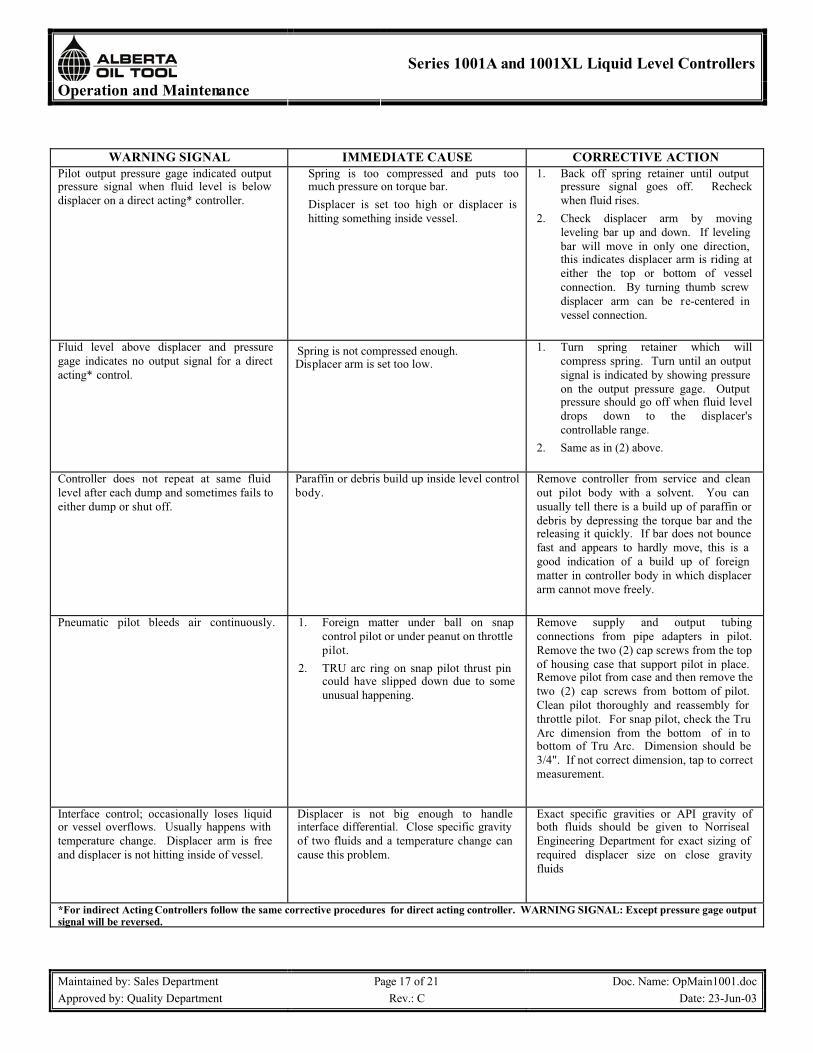
WARNING SIGNAL IMMEDIATE CAUSE CORRECTIVE ACTIONPilot output pressure gage indicated output pressure signal when fluid level is below displacer on a direct acting* controller.
Spring is too compressed and puts toomuch pressure on torque bar. Displacer is set too high or displacer is hitting something inside vessel.
1. Back off spring retainer until output pressure signal goes off. Recheckwhen fluid rises.
2. Check displacer arm by movingleveling bar up and down. If leveling bar will move in only one direction, this indicates displacer arm is riding at either the top or bottom of vesselconnection. By turning thumb screw displacer arm can be re-centered in vessel connection.
Fluid level above displacer and pressuregage indicates no output signal for a direct acting* control.
Spring is not compressed enough.Displacer arm is set too low.
1. Turn spring retainer which willcompress spring. Turn until an output signal is indicated by showing pressure on the output pressure gage. Output pressure should go off when fluid level drops down to the displacer'scontrollable range.
2. Same as in (2) above.
Controller does not repeat at same fluid level after each dump and sometimes fails to either dump or shut off.
Paraffin or debris build up inside level control body.
Remove controller from service and clean out pilot body with a solvent. You can usually tell there is a build up of paraffin or debris by depressing the torque bar and the releasing it quickly. If bar does not bounce fast and appears to hardly move, this is a good indication of a build up of foreign matter in controller body in which displacer arm cannot move freely.
Pneumatic pilot bleeds air continuously. 1. Foreign matter under ball on snapcontrol pilot or under peanut on throttle pilot.
2. TRU arc ring on snap pilot thrust pin could have slipped down due to someunusual happening.
Remove supply and output tubingconnections from pipe adapters in pilot.Remove the two (2) cap screws from the top of housing case that support pilot in place.Remove pilot from case and then remove the two (2) cap screws from bottom of pilot.Clean pilot thoroughly and reassembly for throttle pilot. For snap pilot, check the Tru Arc dimension from the bottom of in to bottom of Tru Arc. Dimension should be 3/4". If not correct dimension, tap to correct measurement.
Interface control; occasionally loses liquid or vessel overflows. Usually happens with temperature change. Displacer arm is free and displacer is not hitting inside of vessel.
Displacer is not big enough to handleinterface differential. Close specific gravity of two fluids and a temperature change can cause this problem.
Exact specific gravities or API gravity ofboth fluids should be given to Norriseal Engineering Department for exact sizing of required displacer size on close gravityfluids
*For indirect Acting Controllers follow the same corrective procedures for direct acting controller. WARNING SIGNAL: Except pressure gage output signal will be reversed.
Operation and Maintenance
Series 1001A and 1001XL Liquid Level Controllers
Maintained by: Sales Department Page 18 of 21 Doc. Name: OpMain1001.docApproved by: Quality Department Rev.: C Date: 23-Jun-03
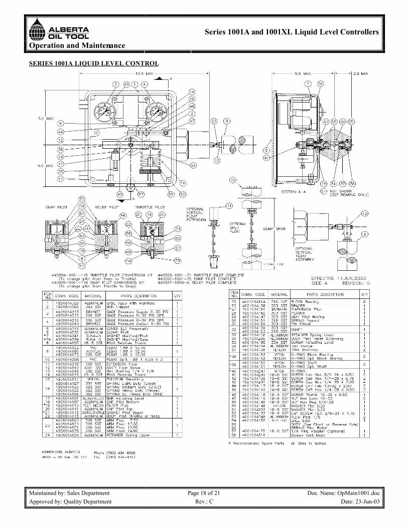
SERIES 1001A LIQUID LEVEL CONTROL
Operation and Maintenance
Series 1001A and 1001XL Liquid Level Controllers
Maintained by: Sales Department Page 19 of 21 Doc. Name: OpMain1001.docApproved by: Quality Department Rev.: C Date: 23-Jun-03
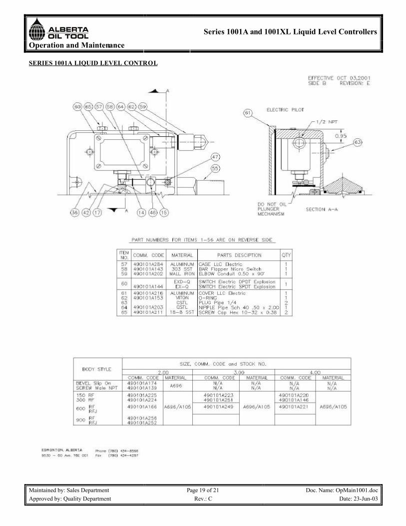
SERIES 1001A LIQUID LEVEL CONTROL

Operation and Maintenance
Series 1001A and 1001XL Liquid Level Controllers
Maintained by: Sales Department Page 20 of 21 Doc. Name: OpMain1001.docApproved by: Quality Department Rev.: C Date: 23-Jun-03
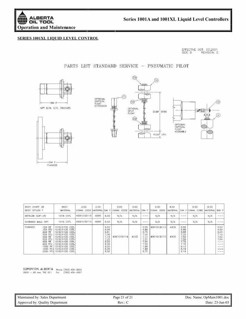
SERIES 1001XL LIQUID LEVEL CONTROL
Operation and Maintenance
Series 1001A and 1001XL Liquid Level Controllers
Maintained by: Sales Department Page 21 of 21 Doc. Name: OpMain1001.docApproved by: Quality Department Rev.: C Date: 23-Jun-03
SERIES 1001XL LIQUID LEVEL CONTROL