Noritz 2009 Product Catalog · Gas Consumption LP Capacity Range Energy Factor Noritz backs its...
12
This product catalog is for professional use only. Noritz 2009 Product Catalog
-
Upload
nguyenhanh -
Category
Documents
-
view
217 -
download
0
Transcript of Noritz 2009 Product Catalog · Gas Consumption LP Capacity Range Energy Factor Noritz backs its...

This product catalog is for professional use only.
Noritz 2009 Product Catalog
E�ciency
Temperature Settings
Included Accessories
DimensionsWeight/ Connections
NGLPGas Consumption
Capacity RangeEnergy Factor
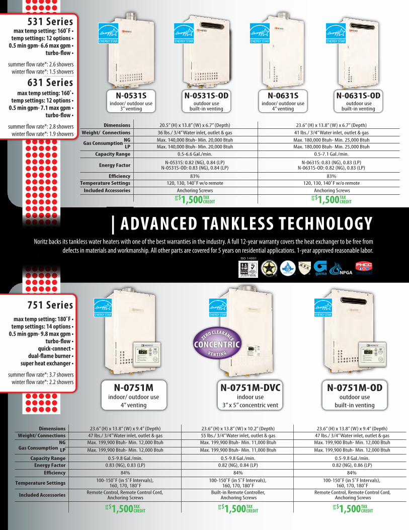
Noritz backs its tankless water heaters with one of the best warranties in the industry. A full 12-year warranty covers the heat exchanger to be free from defects in materials and workmanship. All other parts are covered for 5 years on residential applications. 1-year approved reasonable labor.
| ADVANCED TANKLESS TECHNOLOGY
531 Seriesmax temp setting: 160˚F •
temp settings: 12 options •0.5 min gpm- 6.6 max gpm •
turbo-flow •
summer �ow rate*: 2.6 showerswinter �ow rate*: 1.5 showers
631 Seriesmax temp setting: 160˚•
temp settings: 12 options •0.5 min gpm- 7.1 max gpm •
turbo-flow •
summer �ow rate*: 2.8 showerswinter �ow rate*: 1.9 showers
751 Seriesmax temp setting: 180˚F •
temp settings: 14 options •0.5 min gpm- 9.8 max gpm •
turbo-flow •quick-connect •
dual-flame burner •super heat exchanger •
summer �ow rate*: 3.7 showerswinter �ow rate*: 2.2 showers
23.6” (H) x 13.8” (W) x 9.4” (Depth)47 lbs./ 3/4” Water inlet, outlet & gasMax. 199,900 Btuh- Min. 12,000 BtuhMax. 199,900 Btuh- Min. 12,000 Btuh
0.5-9.8 Gal./min.0.83 (NG), 0.83 (LP)
84%100-150˚F (in 5˚F Intervals),
160, 170, 180˚FRemote Control, Remote Control Cord,
Anchoring Screws
23.6” (H) x 13.8” (W) x 10.2” (Depth)55 lbs./ 3/4” Water inlet, outlet & gasMax. 199,900 Btuh- Min. 11,000 BtuhMax. 199,900 Btuh- Min. 11,000 Btuh
0.5-9.8 Gal./min.0.82 (NG), 0.84 (LP)
84%100-150˚F (in 5˚F Intervals),
160, 170, 180˚FBuilt-in Remote Controller,
Anchoring ScrewsRemote Control, Remote Control Cord,
Anchoring Screws
23.6” (H) x 13.8” (W) x 9.4” (Depth)47 lbs./ 3/4” Water inlet, outlet & gasMax. 199,900 Btuh- Min. 12,000 BtuhMax. 199,900 Btuh- Min. 12,000 Btuh
0.5-9.8 Gal./min.0.82 (NG), 0.86 (LP)
84%100-150˚F (in 5˚F Intervals),
160, 170, 180˚F
PLUMBING-HEATING-COOLINGCONTRACTORS ASSOCIATION
N-0751Mindoor/ outdoor use
4” venting
N-0751M-DVCindoor use
3” x 5” concentric vent
CONCENTRICV E N T I N G
ZERO CLEARANCE
N-0751M-ODoutdoor use
built-in venting
N-0631Sindoor/ outdoor use
4” venting
N-0631S-OD outdoor use
built-in venting
N-0531S-ODoutdoor use
built-in venting
N-0531Sindoor/ outdoor use
3” venting
20.5” (H) x 13.8” (W) x 6.7” (Depth)36 lbs./ 3/4” Water inlet, outlet & gasMax. 140,000 Btuh- Min. 20,000 BtuhMax. 140,000 Btuh- Min. 20,000 Btuh
0.5-6.6 Gal./min.
N-0531S: 0.82 (NG), 0.84 (LP)N-0531S-OD: 0.83 (NG), 0.84 (LP)
83%120, 130, 140˚F w/o remote
Anchoring Screws
23.6” (H) x 13.8” (W) x 6.7” (Depth)41 lbs./ 3/4” Water inlet, outlet & gasMax. 180,000 Btuh- Min. 25,000 BtuhMax. 180,000 Btuh- Min. 25,000 Btuh
0.5-7.1 Gal./min.
N-0631S: 0.83 (NG), 0.83 (LP)N-0631S-OD: 0.82 (NG), 0.83 (LP)
83%120, 130, 140˚F w/o remote
Anchoring Screws
E�ciencyTemperature Settings
Included Accessories
DimensionsWeight/ Connections
NGLP
Gas Consumption
Capacity Range
Energy Factor

NA**84%
24.2” (H) x 18.3” (W) x 9.4” (Depth)62 lbs./ 3/4” Water inlet, outlet & gasMax. 250,000 Btuh- Min. 11,000 BtuhMax. 250,000 Btuh- Min. 11,000 Btuh
0.5-11.1 Gal./min.NA**84%
100-150˚F (in 5˚F Intervals), 160, 170, 180˚F
Remote Control, Remote Control Cord,Anchoring Screws
24.2” (H) x 18.3” (W) x 9.4” (Depth)62 lbs./ 3/4” Water inlet, outlet & gasMax. 250,000 Btuh- Min. 11,000 BtuhMax. 250,000 Btuh- Min. 11,000 Btuh
0.5-11.1 Gal./min.
100-150˚F (in 5˚F Intervals), 160, 170, 180˚F
Remote Control, Remote Control Cord,Anchoring Screws
24.2” (H) x 18.3” (W) x 9.4” (Depth)62 lbs./ 3/4” Water inlet, outlet & gasMax. 250,000 Btuh- Min. 11,000 BtuhMax. 250,000 Btuh- Min. 11,000 Btuh
0.5-11.1 Gal./min.NA**84%
100-150˚F (in 5˚F Intervals), 160, 170, 180˚F
Remote Control, Remote Control Cord,Anchoring Screws
N-0931Mindoor/ outdoor use
4” venting
N-0931M-DVindoor use
4” direct venting
N-0931M-ODoutdoor use
built-in venting
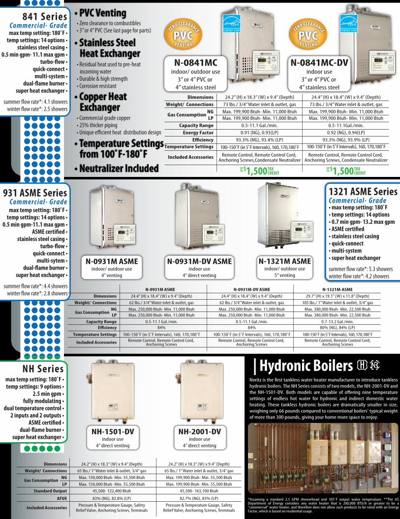
max temp setting: 180˚F •temp settings: 14 options •
0.5 min gpm- 11.1 max gpm •turbo-flow •
quick-connect•dual-flame burner •
super heat exchanger •
summer �ow rate*: 4.1 showerswinter �ow rate*: 2.5 showers
842 Series
max temp setting: 180˚F•temp settings: 14 options •
0.5 min gpm- 11.1 max gpm •turbo-flow •
quick-connect •dual-flame burner •
super heat exchanger •
summer �ow rate*: 4.4 showerswinter �ow rate*: 2.8 showers
931 Series
| Industry 1st Dual Flame Burner | Super Heat ExchangerNew dual �ame burner
The heat exchanger was re-engineered to increase thermal e�ciency. The piping is 25% thicker to help prevent condensation and erosion to ensure a longer life.
The newly designed burner gives Noritz units stable combustion over a wider range of water �ow. The burners maximize output and provide temperature stability while maintaining low emissions.
N-0842MCindoor/ outdoor use
3” or 4” PVC only
N-0842MC-DVindoor use
3” or 4” PVC only
• Zero clearance to combustibles• 3” or 4” PVC (See last page for parts)
• Residual heat used to pre-heat incoming water• Durable & high strength• Corrosion resistant
• Commercial grade copper• 25% thicker piping• Unique efficient heat distribution design
• Neutralizer Included
• Built-in PVC Adapter
• Stainless Steel Heat Exchanger
• Copper Heat Exchanger
• Temperature Settings from 100˚F-180˚F
PVCV E N T I N G
ZERO CLEARANCE PVCV E N T I N G
ZERO CLEARANCE
E�ciencyTemperature Settings
Included Accessories
DimensionsWeight/ Connections
NGLP
Gas Consumption
Capacity RangeEnergy Factor
24.2” (H) x 18.3” (W) x 9.4” (Depth)74 lbs./ 3/4” Water inlet & outlet, gasMax. 199,900 Btuh- Min. 11,000 BtuhMax. 199,900 Btuh- Min. 11,000 Btuh
0.5-11.1 Gal./min.0.91 (NG), 0.93(LP)
Remote Control, Remote Control Cord, Anchoring Screws,Condensate Neutralizer
93.3% (NG), 93.4% (LP)100-150˚F (in 5˚F Intervals), 160, 170,180˚F
24.4” (H) x 18.4” (W) x 9.4” (Depth)74 lbs./ 3/4” Water inlet & outlet, gasMax. 199,900 Btuh- Min. 11,000 BtuhMax. 199,900 Btuh- Min. 11,000 Btuh
0.5-11.1 Gal./min.0.92 (NG), 0.94(LP)
Remote Control, Remote Control Cord, Anchoring Screws, Condensate Neutralizer
93.3% (NG), 93.9% (LP)100-150˚F (in 5˚F Intervals), 160, 170,180˚F
E�ciency
Temperature Settings
Included Accessories
DimensionsWeight/ Connections
NGLPGas Consumption
Capacity RangeEnergy Factor
N-0841MCindoor/ outdoor use
3” or 4” PVC or 4” stainless steel
N-0841MC-DVindoor use
3” or 4” PVC or 4” stainless steel
N-1321M ASMEindoor/ outdoor use
5” venting
Noritz is the �rst tankless water heater manufacturer to introduce tankless hydronic boilers. The NH Series consists of two models, the NH-2001-DV and the NH-1501-DV. Both models are capable of o�ering nine temperature settings of endless hot water for hydronic and indirect domestic water heating. These tankless hydronic boilers are dramatically smaller in size, weighing only 66 pounds compared to conventional boilers’ typical weight of more than 300 pounds, giving your home more space to enjoy.
| Hydronic Boilers
• Zero clearance to combustibles• 3” or 4” PVC (See last page for parts)
• Residual heat used to pre-heat incoming water• Durable & high strength• Corrosion resistant
• Commercial grade copper• 25% thicker piping• Unique efficient heat distribution design
• Neutralizer Included
• PVC Venting
• Stainless Steel Heat Exchanger
• Copper Heat Exchanger
• Temperature Settings from 100˚F-180˚F
1321 ASME SeriesCommerc ial- Grade• max temp setting: 180˚F• temp settings: 14 options• 0.7 min gpm- 13.2 max gpm• ASME certified• stainless steel casing• quick-connect• multi-system• super heat exchanger
summer �ow rate*: 5.3 showerswinter �ow rate*: 4.2 showers
931 ASME SeriesCommerc ial- Grademax temp setting: 180˚F •
temp settings: 14 options •0.5 min gpm-11.1 max gpm •
ASME certified •stainless steel casing •
turbo-flow •quick-connect •
multi-sytem •dual-flame burner •
super heat exchanger •
summer �ow rate*: 4.4 showerswinter �ow rate*: 2.8 showers
841 SeriesCommerc ial- Grademax temp setting: 180˚F •
temp settings: 14 options •stainless steel casing •
0.5 min gpm- 11.1 max gpm •turbo-flow •
quick-connect •multi-system •
dual-flame burner •super heat exchanger •
summer �ow rate*: 4.1 showerswinter �ow rate*: 2.5 showers
PVCV E N T I N G
ZERO CLEARANCE PVCV E N T I N G
ZERO CLEARANCE
NH-1501-DVindoor use
4” direct venting
NH-2001-DVindoor use
4” direct venting
N-0931M ASMEindoor/ outdoor use
4” venting
N-0931M-DV ASMEindoor use
4” direct venting
24.2” (H) x 18.3” (W) x 9.4” (Depth)65 lbs./ 1” Water inlet & outlet, 3/4” gas 65 lbs./ 1” Water inlet & outlet, 3/4” gasMax. 150,000 Btuh- Min. 55,500 BtuhMax. 150,000 Btuh- Min. 55,500 Btuh
45,500- 122,400 Btuh
Pressure & Temperature Gauge, SafetyRelief Valve, Anchoring Screws, Terminals
83% (NG), 82.8% (LP)
24.2” (H) x 18.3” (W) x 9.4” (Depth)
Max. 199,900 Btuh- Min. 55,500 BtuhMax. 199,900 Btuh- Min. 55,500 Btuh
45,500- 163,100 Btuh
Pressure & Temperature Gauge, SafetyRelief Valve, Anchoring Screws, Terminals
82.7% (NG), 83% (LP)AFUE
Included Accessories
DimensionsWeight/ Connections
NGLP
Gas Consumption
Standard Output
24.4” (H) x 18.4” (W) x 9.4” (Depth)62 lbs./ 3/4” Water inlet & outlet, gas 62 lbs./ 3/4” Water inlet & outlet, gasMax. 250,000 Btuh- Min. 11,000 BtuhMax. 250,000 Btuh- Min. 11,000 Btuh
0.5-11.1 Gal./min.
Remote Control, Remote Control Cord, Anchoring Screws
84% 84%
100-150˚F (in 5˚F Intervals), 160, 170,180˚F
24.4” (H) x 18.4” (W) x 9.4” (Depth)
Max. 250,000 Btuh- Min. 11,000 BtuhMax. 250,000 Btuh- Min. 11,000 Btuh
0.5-11.1 Gal./min.
Remote Control, Remote Control Cord, Anchoring Screws
100-150˚F (in 5˚F Intervals), 160, 170,180˚F
E�ciencyTemperature Settings
Included Accessories
DimensionsWeight/ Connections
NGLP
Gas Consumption
Capacity Range
29.7” (H) x 19.1” (W) x 11.8” (Depth)N-0931M ASME N-0931M-DV ASME N-1321M-ASME
105 lbs./ 1” Water inlet & outlet, 3/4” gasMax. 380,000 Btuh- Min. 22,500 BtuhMax. 380,000 Btuh- Min. 22,500 Btuh
0.7-13.2 Gal./min.
Remote Control, Remote Control Cord,Anchoring Screws
80% (NG), 84% (LP)
100-150˚F (in 5˚F Intervals), 160, 170,180˚F
NH Seriesmax temp setting: 180˚F •temp settings: 9 options •
2.5 min gpm •fully modulating •
dual temperature control •2 inputs and 2 outputs •
ASME certified •dual-flame burner •
super heat exchanger •
E�ciencyTemperature Settings
Included Accessories
DimensionsWeight/ Connections
NGLP
Gas Consumption
Capacity RangeEnergy Factor
24.2” (H) x 18.3” (W) x 9.4” (Depth)73 lbs./ 3/4” Water inlet & outlet, gasMax. 199,900 Btuh- Min. 11,000 BtuhMax. 199,900 Btuh- Min. 11,000 Btuh
0.5-11.1 Gal./min.0.91 (NG), 0.93(LP)
Remote Control, Remote Control Cord, Anchoring Screws,Condensate Neutralizer
93.3% (NG), 93.4% (LP)100-150˚F (in 5˚F Intervals), 160, 170,180˚F
24.4” (H) x 18.4” (W) x 9.4” (Depth)73 lbs./ 3/4” Water inlet & outlet, gasMax. 199,900 Btuh- Min. 11,000 BtuhMax. 199,900 Btuh- Min. 11,000 Btuh
0.5-11.1Gal./min.0.92 (NG), 0.94(LP)
Remote Control, Remote Control Cord, Anchoring Screws, Condensate Neutralizer
93.3% (NG), 93.9% (LP)100-150˚F (in 5˚F Intervals), 160, 170,180˚F
*Assuming a standard 2.5 GPM showerhead and 105˚F output water temperature. **The US Department of Energy considers any water heater that is 200,000 BTU/h or greater to be a “commercial” water heater, and therefore does not allow such products to be rated with an Energy Factor, which is based on residential usage.
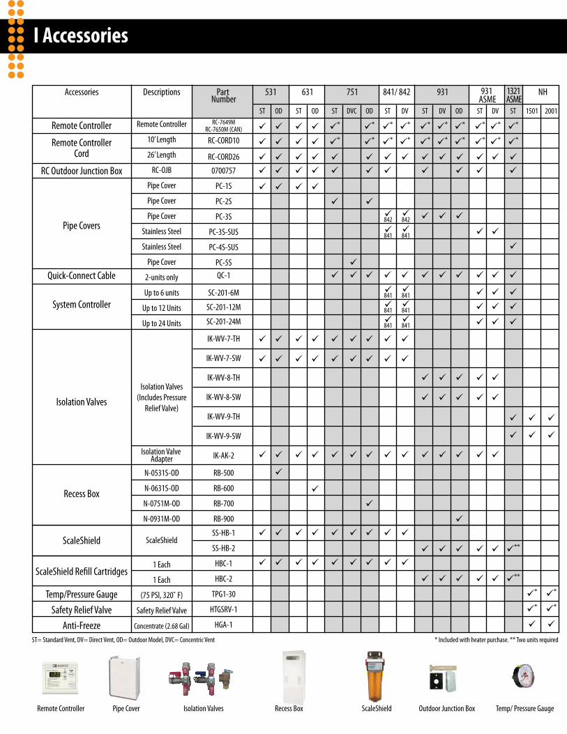
І Accessories
Remote Controller Outdoor Junction Box Temp/ Pressure GaugeRecess Box ScaleShieldPipe Cover
531Accessories Descriptions Part Number
631 751 841/ 842 931 931 ASME
1321 ASME
NH
Remote Controller
Remote ControllerCord
RC-7649MRC-7650M (CAN)
841 841
RC-CORD26
0700757
RC-CORD10
Pipe Covers
RC Outdoor Junction Box
QC-1
SC-201-6M
SC-201-12M
SC-201-24M
IK-WV-7-TH
IK-WV-7-SW
IK-WV-8-TH
IK-WV-8-SW
IK-WV-9-TH
IK-WV-9-SW
IK-AK-2
RB-500
RB-600
RB-700
RB-900
SS-HB-1
SS-HB-2
HBC-1
HBC-2
TPG1-30
HTGSRV-1
HGA-1
Quick-Connect Cable
System ControllerUp to 6 units
Up to 12 Units
Up to 24 Units
Isolation Valves(Includes Pressure
Relief Valve)
Isolation Valve Adapter
Remote Controller
10’ Length
26’ Length
RC-OJB
Pipe Cover
Pipe Cover
Pipe Cover
Stainless Steel
Stainless Steel
Pipe Cover
2-units only
PC-1S
PC-2S
PC-3S
PC-3S-SUS
PC-4S-SUS
PC-5S
Isolation Valves
Recess Box
N-0531S-OD
N-0631S-OD
N-0751M-OD
N-0931M-OD
ScaleShield ScaleShield
1 Each
1 Each
(75 PSI, 320˚ F)
Safety Relief Valve
Concentrate (2.68 Gal)
ScaleShield Re�ll Cartridges
Temp/Pressure GaugeSafety Relief Valve
Anti-Freeze
2001
*
*
DV
*
*
DV
*
*
OD
*
*
DV
*
*
DVC
OD
*
*
ST
*
*
**
**
ST
*
*
ST
*
*
ST
*
*
841 841
841 841
841 841
842 842
ST
*
*
ST
ST
OD
OD
1501
*
*
ST= Standard Vent, DV= Direct Vent, OD= Outdoor Model, DVC= Concentric Vent * Included with heater purchase. ** Two units required
Isolation Valves

Noritz N-Vent is available in three sizes: 3”, 4” and 5”. N-Vent is UL-Listed and ideal for tankless installations such as direct vent, horizontal, vertical and outdoor applications. Adjustable venting o�ers �exibility for di�erent vent runs.
І Noritz Stainless Steel Venting: The N-Vent Line· The N-Vent Cat III Venting
· The N-Vent Termination Kits
· The Line-up: 3”, 4” & 5”
Noritz N-Vent is UL approved Category III venting. Underwriter’s Laboratories (UL), an independent not-for-pro�t product safety testing and certi�cation organization is one of the most recognized safety agencies in the world. N-Vent is approved for tankless and boiler stainless steel exhaust installations at a fraction of the industry standard cost.
· UL Listed
N-Vent Horizontal Vent KitVK4-H-*Speci�cations & Features• Stainless Steel• 4” Diameter• Flexibility for different wall thicknesses• Easy installation• Professional appearance
N-Vent Vertical Vent KitVK4-V1Speci�cations & Features• Stainless Steel• 4” Diameter• Easy installation• Professional appearance
Noritz supplies easy-to-connect venting components- the most simple in the industry to install. Unlike other brands, there’s no need to tighten as the Noritz N-Vent has a Quick-Snap feature that allows for an easy
· Easy Connection
connection while forming a tight seal. In addition, Noritz o�ers a special appliance adapter that connects N-Vent components to other manufacturers’ tankless heaters or boilers.
Wall Thickness7”- 8”
8”- 10.3”10.5”- 14.5”
DescriptionWall Thimble with Built-in
Hood Termination90 Degree Elbow
9”- 13.4” Adjustable Vent
Description
Drain Tee
90 Degree Elbow
Firestop
Support Clamp
Roof Jack
Storm Collar Pipe
Rain Cap
9”- 13.4” Adjustable Vent
Part Number
DT4
VP4-90ELB
FS4
SC4
RJ4
SCP4
RC4
VP4-13.4ADJ
Quantity
1
2
1
1
1
1
1
1
Part NumberWT4-H-# (# Based on wall thickness)
VP4-90ELB
VP4-9.4ADJ (For Kit VK4-H-8-1 ONLY)
VP4-13.4ADJ (For Kits: VK4-H-10 & VK4-H-14)
Quantity1
1
1
1
*Venting Kit NumberVK4-H-8-1VK4-H-10VK4-H-14
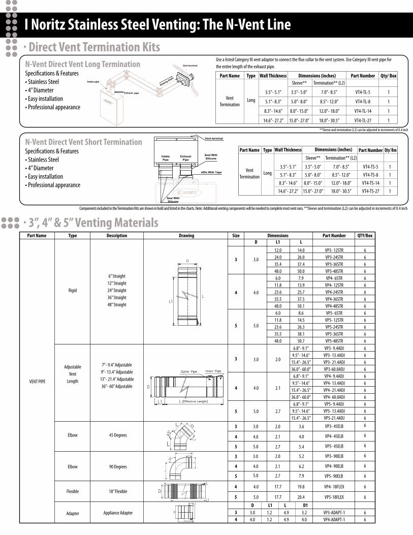
І Noritz Stainless Steel Venting: The N-Vent Line· Direct Vent Termination Kits
· 3”, 4” & 5” Venting Materials
N-Vent Direct Vent Long TerminationSpeci�cations & Features• Stainless Steel• 4” Diameter• Easy installation• Professional appearance
Use a listed Category III vent adaptor to connect the flue collar to the vent system. Use Category III vent pipe for the entire length of the exhaust pipe.
**Sleeve and termination (L2) can be adjusted in increments of 0.4 inch
Components included in the Termination Kits are shown in bold and listed in the charts. Note: Additional venting components will be needed to complete most vent runs. **Sleeve and termination (L2) can be adjusted in increments of 0.4 inch
N-Vent Direct Vent Short TerminationSpeci�cations & Features• Stainless Steel• 4” Diameter• Easy installation• Professional appearance
Part Name Type Description Drawing Size DimensionsD
D L1 L D1
3
4
5
3.0
4.0
5.0
3.0
3.0
3.0
4.0
4.0
4.0
5.0
5.0
5.0
2.0
2.1
2.7
3
3
4
4
3
4
5
3
4
5
5
L1 LPart Number QTY/Box
6” Straight12” Straight24” Straight36” Straight48” Straight
7”- 9.4” Adjustable9”- 13.4” Adjustable
13”- 21.4” Adjustable36”- 60” Adjustable
Rigid
VENT PIPE
AdjustableVent
Length
Adapter Appliance Adapter
Flexible 18” Flexible
Elbow 45 Degrees
Elbow 90 Degrees
12.024.035.448.06.0
11.823.635.548.06.0
11.823.635.548.0
14.026.037.450.07.9
13.925.737.550.18.6
14.526.338.150.7
VP3- 12STRVP3-24STRVP3-36STRVP3-48STRVP4- 6STR
VP4- 12STRVP4-24STRVP4-36STRVP4-48STRVP5- 6STR
VP5- 12STRVP5-24STRVP5-36STRVP5-48STR
VP3- 9.4ADJVP3- 13.4ADJVP3- 21.4ADJVP3-60.0ADJVP4- 9.4ADJ
VP4- 13.4ADJVP4- 21.4ADJVP4- 60.0ADJVP5- 9.4ADJ
VP5- 13.4ADJVP5-21.4ADJ
66666666666666666666666666
6
6
6
6
6
66
6
6
6.8”- 9.1”9.5”- 14.6”
15.4”- 26.5”36.0”- 60.0”
6.8”- 9.1”9.5”- 14.6”
15.4”- 26.5”36.0”- 60.0”
6.8”- 9.1”9.5”- 14.6”
15.4”- 26.5”
2.0
2.1
2.7
2.0
2.1
2.7
3.6
4.0
5.4
5.2
6.2
7.9
VP3- 45ELB
VP4- 45ELB
VP5- 45ELB
VP3- 90ELB
VP4- 90ELB
VP5- 90ELB
VP3-ADAPT-1VP4-ADAPT-1
17.7
17.7
4.0
5.0
4
5
19.8
20.4
VP4- 18FLEX
VP5-18FLEX
3.04.0
1.21.2
4.94.9
3.24.0
Part Name
VentTermination
Part Name
VentTermination
Type
Long
Type
Long
3.5”- 5.1”
5.1”- 8.3”
8.3”- 14.6”
14.6”- 27.2”
3.5”- 5.1”
5.1”- 8.3”
8.3”- 14.6”
14.6”- 27.2”
3.5”- 5.0”
5.0”- 8.0”
8.0”- 15.0”
15.0”- 27.0”
3.5”- 5.0”
5.0”- 8.0”
8.0”- 15.0”
15.0”- 27.0”
7.0”- 8.5”
8.5”- 12.0”
12.0”- 18.0”
18.0”- 30.5”
7.0”- 8.5”
8.5”- 12.0”
12.0”- 18.0”
18.0”- 30.5”
VT4-TL-5
VT4-TL-8
VT4-TL-14
VT4-TL-27
VT4-TS-5
VT4-TS-8
VT4-TS-14
VT4-TS-27
1
1
1
1
1
1
1
1
Wall Thickness
Wall Thickness
Dimensions (inches)
Dimensions (inches)
Sleeve**
Sleeve**
Termination** (L2)
Termination** (L2)
Part Number
Part Number
Qty/ Box
Qty/ Box
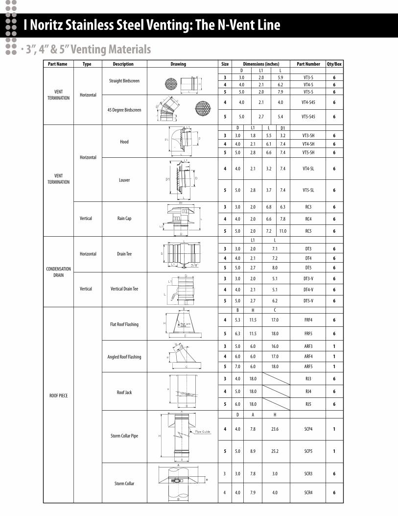
І Noritz Stainless Steel Venting: The N-Vent Line· 3”, 4” & 5” Venting Materials
Straight Birdscreen
HorizontalVENT
TERMINATION
VENTTERMINATION
CONDENSATIONDRAIN
ROOF PIECE
Horizontal
Horizontal
Vertical
Vertical
45 Degree Birdscreen
Hood
Louver
Rain Cap
Drain Tee
Vertical Drain Tee
Flat Roof Flashing
Angled Roof Flashing
Roof Jack
Storm Collar Pipe
Storm Collar
Part Name Type Description Drawing Dimensions (inches)D L1 L
3.04.05.0
2.02.12.0
5.96.27.9
4.0
5.0
2.1
2.7
4.0
5.4
L5.5
6.1
6.6
3.2
3.7
6.8
6.6
7.2
D13.2
7.4
7.4
7.4
7.4
6.3
7.8
11.0
Size
345
3
4
5
4
5
4
5
3
4
5
3
4
5
3
4
5
4
5
3
4
5
3
4
5
4
5
3
4
D
3.0
4.0
5.0
4.0
5.0
3.0
4.0
5.0
3.0
4.0
5.0
3.0
4.0
5.0
5.3
6.3
B
5.0
6.0
7.0
4.0
5.0
6.0
D
4.0
5.0
3.0
4.0
7.1
7.2
8.0
L
5.1
5.1
6.2
C
17.0
18.0
16.0
17.0
18.0
23.6
25.2
H
3.0
4.0
Part Number
VT3-SH
VT4-SH
VT5-SH
VT3-SVT4-SVT5-S
VT4-S45
VT5-S45
VT4-SL
VT5-SL
RC3
RC4
RC5
DT3
DT4
DT5
DT3-V
DT4-V
DT5-V
FRF4
FRF5
ARF3
ARF4
ARF5
RJ3
RJ4
RJ5
SCP4
SCP5
SCR3
SCR4
L1
1.8
2.1
2.8
2.1
2.8
2.0
2.0
2.0
2.0
2.1
2.7
L1
2.0
2.1
2.7
H
11.5
11.5
6.0
6.0
6.0
18.0
18.0
18.0
7.8
8.9
A
7.8
7.9
6
6
1
1
6
6
6
1
1
1
6
6
6
6
6
6
6
6
6
6
6
6
6
6
6
6
Qty/Box
6
6
666

І Noritz Stainless Steel Venting: The N-Vent Line· 3”, 4” & 5” Venting Materials
Horizontal
Size
D3.44.45.4
15.018.020.4
C
Termination** (L2)
345
3.04.05.0
6.06.07.0
Size
D
D A H C
C
5.0- 6.07.0- 9.0
9.0- 14.54.1- 7.86.0- 7.07.0- 8.0
8.0- 10.310.5- 14.5
5.0- 6.06.0- 7.07.0- 8.0
8.0- 10.310.5- 14.5
D1
4.84
L1
.281
E
G
CDB
F
0- 3.10- 5.80- 8.10- 4.8
0- 5.60- 11.1
0- 6.60- 9.6
1.5
Horizontal
DIRECTVENT
TERMINATION
OUTDOORVENT CAP
Part Name
WALLPENETRATION
WALLTERMINATION
SUPPORT
FIRE STOP Vertical Fire Stop
DirectVent
Long
Short
3.5”- 5.1”
5.1”- 8.3”
8.3”- 14.6”
14.6”- 27.2”
Sleeve**
D
7.84
3.5”- 5.0”
5.0”- 8.0”
8.0”- 15.0”
15.0”- 27.0”
3.5”- 5.0”
5.0”- 8.0”
8.0”- 15.0”
15.0”- 27.0”
7.0”- 8.5”
8.5”- 12..0”
12.0”- 18.0”
18.0”- 30.5”
7.0”- 8.5”
8.5”- 12..0”
12.0”- 18.0”
18.0”- 30.5”
3.5”- 5.1”
5.1”- 8.3”
8.3”- 14.6”
14.6”- 27.2”
Vent SleeveCover
Type
Strap
Wall Thimble
Vent Cap
AdjustableWall Thimble
w/ Built-inHood Termination
Clamp
Description Drawing Dimensions (inches)
4.0
7.0
10.7
B
3.1
4.0
5.0
D
6.0
10.0
12.2
C
3
4
5
Size
1
1
1
Qty/Box
Size D E F G
3
4
5
3
4
5
3.0
4.0
5.0
4.0
4.7
6.0
4.65.66.67.65.76.68.7
10.76.87.89.8
11.8
1”2”3”4”1”2”4”6”1”2”4”6”
3.0
4.0
5.0
5.8
B
6.5
7.1
10.7
11.0
C
9.0
10.0
12.2
7.97.9
B
18.9
6.26.2
H
7.6
FS3FS4FS5
FP-4
VT4-TL-5
VT4-TL-8
VT4-TL-14
VT4-TL-27
SC3SC4SC5
VT4-TS-5
VT4-TS-8
VT4-TS-14
VT4-TS-27
SS3-1SS3-2SS3-3SS3-4SS4-1SS4-2SS4-4SS4-6SS5-1SS5-2SS5-4SS5-6
VC-3VC-4-1
WT3-H-6WT3-H-9
WT3-H-14WT4-H-8-1
WT4-H-6WT4-H-7
WT4-H-10WT4-H-14WT5-H-5WT5-H-6WT5-H-7
WT5-H-10WT5-H-14
WT3
WT4
WT5
Part Number
VC-132
666
1
1
1
1
5 Sets5 Sets5 Sets
5 Sets5 Sets5 Sets5 Sets5 Sets5 Sets5 Sets5 Sets5 Sets5 Sets5 Sets5 Sets
66
1111111111111
1
1
1
1
1
1
**Sleeve and termination (L2) can be adjusted in increments of 0.4”
І Noritz Stainless Steel Venting
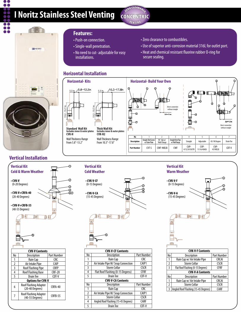
Vertical Installation
CONCENTRICV E N T I N G
ZERO CLEARANCE
CVK-V Contents
Options for CVK-V
No Part Number12345
6
CRCCAIPCRFP
CRF-20
7
CRFA-40
CRFB-55
DescriptionRain Cap
Air Intake PipeRoof Flashing PipeRoof Flashing Base
Roof Flashing Adapter(20-40 Degrees)
Roof Flashing Adapter(40-55 Degrees)
Drain Tee CDT-V
• CVK-V(0-20 Degrees)
• CVK-V+CRFA-40(20-40 Degrees)
• CVK-V+CRFB-55(40-55 Degrees)
1
2
5
346 7
Vertical KitCold & Warm Weather
Horizontal InstallationHorizontal- Kits Horizontal- Build Your Own
Wall Thickness RangeFrom 5.8"-13.2"
Wall Thickness RangeFrom 10.3"-17.8"
1
2
4
6
5
77
1
2
4
Direct connectionwithout straight
4
1
4
8
1
3
3Direct connectionwithout straight
4
Standard Wall KitIncludes inner & outer platesCVK-H
Thick Wall KitIncludes inner & outer platesCVK-H2
• CVK-V-F(0-15 Degrees)
• CVK-V-A(15-45 Degrees)
1
23
Vertical KitWarm Weather
CVK-V-F Contents
CVK-V-A Contents
Storm Collar
Storm Collar
No Description Part Number1
3
Rain Cap w/ Air Intake Pipe
Rain Cap w/ Air Intake Pipe
CRCAICSCR
Flat Roof Flashing (0-15 Degrees) CFRF
No Description Part Number123 Angled Roof Flashing (15-45 Degrees) CARF
2
CRCAICSCR
Features:• Push-on connection.• Single-wall penetration.• No need to cut- adjustable for easy installations.
• Zero clearance to combustibles.• Use of superior anti-corrosion material 316L for outlet port.• Heat and chemical resistant fluorine rubber O-ring for secure sealing.
No
Description
Part Number
1Straight Bird Screen
w/ Outer Plate
CVT-S
3
CWF
Straight Vent Pipe w/ Wall Flange
2
CWF-90ELB
90˚ Adj w/ Wall Flange
4
CVP-4/12/24/36STR
Straight
5
CVP-11/16/40ADJ
Adjustable
CVP-45/90ELB
6
45/ 90 Degree
CDT-V
7
Drain Tee
• CVK-V-CF(0-15 Degrees)
• CVK-V-CA(15-45 Degrees)
5
1
234
Vertical KitCold Weather
CVK-V-CF Contents
CVK-V-CA Contents
No Description Part Number12345
Rain Cap
Storm Collar
Storm Collar
CRCCAIP1CSCR
Flat Roof Flashing (0-15 Degress) CFRF
No Description Part Number12345
Rain Cap CRCCAIP1CSCR
Angled Roof Flashing (15-45 Degrees) CARF
Drain Tee CDT-V
Air Intake Pipe W/ Snap Connection
Air Intake Pipe W/ Snap Connection
Drain Tee CDT-V
13.2
- 15
.7 in
.
13.2
- 15
.7 in
.5.3 in. 5.3 in.
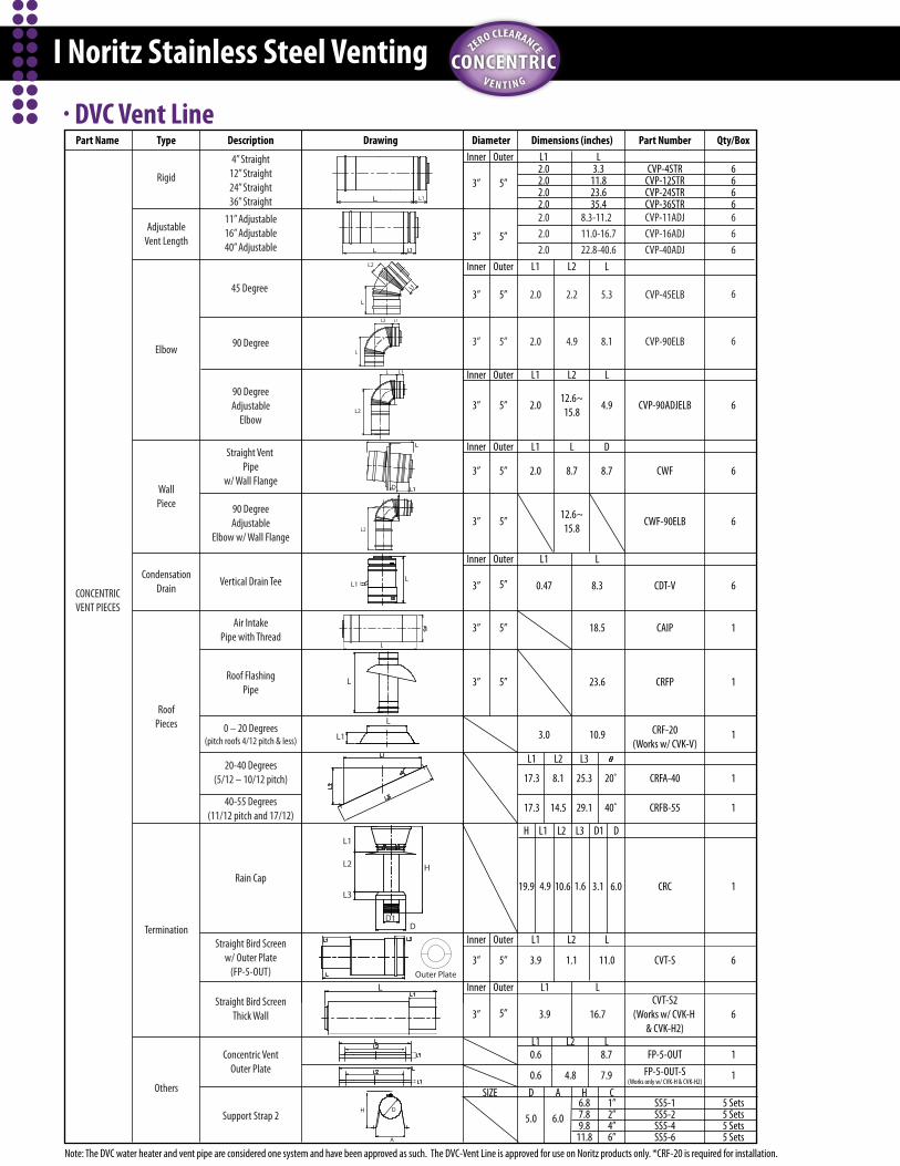
І Noritz Stainless Steel Venting
· DVC Vent LineInner
2.02.02.02.02.02.02.0
L1Outer
Inner Outer
Inner Outer
3” 5”
3” 5”
3” 5”
3” 5”
3” 5”
3.311.823.635.4
L
8.3-11.211.0-16.722.8-40.6
CONCENTRICVENT PIECES
Rigid
4” Straight12” Straight24” Straight36” Straight
11” Adjustable16” Adjustable40” Adjustable
45 Degree
90 Degree
AdjustableVent Length
Elbow
WallPiece
CondensationDrain
RoofPieces
Termination
Others
Roof FlashingPipe
0 – 20 Degrees (pitch roofs 4/12 pitch & less)
20-40 Degrees(5/12 – 10/12 pitch)
40-55 Degrees(11/12 pitch and 17/12)
Straight Bird Screenw/ Outer Plate
(FP-5-OUT) Outer Plate
Straight Bird ScreenThick Wall
Concentric VentOuter Plate
Inner Outer
3” 5”Air IntakePipe with Thread
L2
L
L1L2
90 DegreeAdjustable
Elbow
90 DegreeAdjustable
Elbow w/ Wall Flange3” 5”
3” 5”
3” 5”
3” 5”
3” 5”
L
L
L1
L2
L2
LL1
18.5
L
8.3
23.6
10.9
L1
0.47
3.0
Inner Outer
Inner Outer
L1
17.3
17.3
L2
8.1
14.5
L3
25.3
29.1
20˚
40˚
Inner Outer
3” 5”
Straight Vent Pipe
w/ Wall Flange
12.6~15.8
L2
L2
2.2
4.9
12.6~15.8
L
8.7
L
L
5.3
8.1
4.9
8.7
D
D
L1
L1
2.0
2.0
2.0
2.0
L1
Rain Cap
H
H
19.9 4.9
L1
L1
L1
L
L
L1
10.6
L2
L2
L3
L2
L31.6
D1
D1
3.1
D
D
6.0
3.9
3.9 16.7
1.1 11.0
A
H D
L1 L2 L
ADSIZE
Support Strap 2
Vertical Drain Tee
0.6
0.6
4.8
5.0 6.0
7.9
8.7
CONCENTRICV E N T I N G
ZERO CLEARANCE
Note: The DVC water heater and vent pipe are considered one system and have been approved as such. The DVC-Vent Line is approved for use on Noritz products only. *CRF-20 is required for installation.
H6.87.89.8
11.8
C1”2”4”6”
Part Name Type Description Drawing Dimensions (inches)Diameter
1
1
5 Sets5 Sets5 Sets5 Sets
6
6
1
1
1
1
1
1
6
6
6
6
6
6
6666666
Qty/Box
FP-5-OUT-S(Works only w/ CVK-H & CVK-H2)
FP-5-OUT
SS5-1SS5-2SS5-4SS5-6
CVT-S2(Works w/ CVK-H
& CVK-H2)
CVT-S
CRC
CRFA-40
CRFB-55
CRF-20(Works w/ CVK-V)
CRFP
CAIP
CDT-V
CWF-90ELB
CVP-90ADJELB
CWF
CVP-45ELB
CVP-90ELB
CVP-4STRCVP-12STRCVP-24STRCVP-36STRCVP-11ADJCVP-16ADJCVP-40ADJ
Part Number

Vertical Vent TerminationPVC/CPVC Materials Only
Fire stop
Fire stop/Support
RoofFlashing
StormCollar
HangerStrap
PVC/CPVCAdapter*
**1' Min
* Not supplied with water heater, order separately.
**1' minimum recommended,but not required.
Support
Insert BirdScreen* inend of 45 ° elbow
PVC/CPVCCoupling
Slope ventUpwards
(841 Series Only)
(VT_-PVCS )
Horizontal Vent Termination- PVC/CPVC Materials Only
PVC/CPVCAdapter*
HangerStraps
**1' Minimum
Slope ventUpwards
* Not supplied with water heater, order separately.
**1' minimum recommended,but not required.
Insert BirdScreen* ineach end of tee
Insert BirdScreen* ineach end of tee
PVC/CPVCCoupling
(VP4-ADAPT-PVC)
(VT_-PVCS )
(VT_-PVCS )
1for N-0841MC & N-0842MC only.2items required for use with PVC venting. 3for N-0841MC-DV only.
Part Number
VP4-ADAPT-PVC (4”)
VC-4C
Description
Outdoor Vent Cap1
PVC Adapter2
Bird Screen for PVC2
Short Termination Adapter3
VP4x3-ADAPT-PVC (3”)
VT3-PVCS (3”) VT4-PVCS (4”) VT4-TS-ADAPT
Outdoor Vent Cap(VC-4C)
N-0841MC & N-0842MC PVC Vent Pieces
І Noritz 841 & 842 Series Venting
І Noritz Showrooms & O�ces
І Sizing Reference
PVCV E N T I N G
ZERO CLEARANCE
(Assuming a standard 2.5 GPM showerhead and 105˚F output water temperature).
VK3-H-PVCSpeci�cations & Features:3” Diameter for intake/exhaust**5” Diameter for terminationEasy Installation
3” PVC Concentric Horizontal Termination Kit
39”
5”3”
3”
**Two VP4x3-ADAPT-PVC will be required for conversion. Follow all vent system requirements in accordance with relevant local or state regulation, or, in the absence of local or state code, the National Fuel Gas Code ANSI Z233.1/NGPA 54- latest edition.
Headquarters • 11160 Grace Avenue, Fountain Valley, CA 92708 • Fax: (714) 241-1196Atlanta • 1220 N. Kennestone Circle, Marietta, GA 30066 • Fax: (770)422-0184Chicago • 861 Busse Road, Elk Grove Village, IL 60007 • Fax: (847) 472-6885Dallas • 720 Industrial Boulevard, Ste 200, Grapevine, TX 76051 • Fax: (817) 421-0033New York • 12 Skyline Drive, Hawthorne, NY 10532 • Fax: (914) 345-3288
ShowroomLocations
www.noritz.com/proToll Free: (888) 382- 6568
2009 SEPT© 2009 Noritz America® Corporation. All rights reserved.
(For peak �ow rates in shaded areas, contact Noritz for proper setting.)
TempRise (˚F)
1321Series
931Series
841/842Series
751Series
631Series
531Series
35404550556065707580859095
100
13.213.213.212.511.310.49.68.98.37.87.96.96.66.2
11.110.59.38.47.67.06.56.05.65.34.94.74.44.2
10.69.38.47.46.86.25.85.35.04.64.44.13.93.7
9.28.47.56.76.15.65.24.84.54.24.03.73.53.4
7.17.16.35.85.24.84.44.13.83.63.43.23.02.9
6.65.75.34.64.23.83.53.33.12.92.72.62.42.3
1321
931
841/842
751
631
531
series
series
series
series
series
series
Summer Water Supply 70˚FModel Winter Water Supply 45˚F5.3
Showers
4.4Showers
4.1Showers
3.7Showers
2.8Showers
2.6Showers
4.2Showers
2.8Showers
2.5Showers
2.2Showers
1.9Showers
1.5Showers
13.2 GPM
11.1GPM
10.6GPM
9.2GPM
7.1GPM
6.6GPM
10.4GPM
7.0GPM
6.2GPM
5.6GPM
4.8GPM
3.8GPM
(N-0841MC-DV & N-0842 MC-DV only)
(For 841 Series Only)
(841 Series Only)