Norgren Air Preparation Products and · PDF fileNorgren Air Preparation Products and...
473
Littleton, CO USA Phone 303-794-2611 Fax 303-795-9487 ALE-0-1 APC-104 Contents 2001 Norgren Air Preparation Products and Accessories Compressed Air Systems . . . . . . . . . . . . . . . . . . . . . . . . . . . . . ALE-0-2 Filters . . . . . . . . . . . . . . . . . . . . . . . . . . . . . . . . . . . . . . . . . . . . ALE-1-A Oil Removal (Coalescing) Filters . . . . . . . . . . . . . . . . . . . . . . . ALE-2-1 Oil Vapor Removal (Adsorbing) Filters . . . . . . . . . . . . . . . . . . . ALE-3-1 Membrane Dryers . . . . . . . . . . . . . . . . . . . . . . . . . . . . . . . . . . . ALE-4-1 Regulators . . . . . . . . . . . . . . . . . . . . . . . . . . . . . . . . . . . . . . . . ALE-5-A Specialty Regulators . . . . . . . . . . . . . . . . . . . . . . . . . . . . . . . . . ALE-6-1 Manifold Regulators . . . . . . . . . . . . . . . . . . . . . . . . . . . . . . . . . ALE-7-1 Precision and Instrument Regulators . . . . . . . . . . . . . . . . . . . ALE-8-1 Pilot Regulators . . . . . . . . . . . . . . . . . . . . . . . . . . . . . . . . . . . . ALE-9-1 Pilot Operated Regulators . . . . . . . . . . . . . . . . . . . . . . . . . . . ALE-10-1 U.L. Listed Cylinder Gas Regulators for Industrial Use . . . . . ALE-11-1 U.L. Listed Beverage Regulators . . . . . . . . . . . . . . . . . . . . . . ALE-12-1 Filter/Regulators . . . . . . . . . . . . . . . . . . . . . . . . . . . . . . . . . . . ALE-13-1 Lubricators . . . . . . . . . . . . . . . . . . . . . . . . . . . . . . . . . . . . . . . ALE-14-A Pressure Relief Valves . . . . . . . . . . . . . . . . . . . . . . . . . . . . . . ALE-15-1 Shut-Off and Lockout Valves . . . . . . . . . . . . . . . . . . . . . . . . . ALE-16-1 Stainless Steel Products. . . . . . . . . . . . . . . . . . . . . . . . . . . . . ALE-17-1 Smooth Start, and Directional Control Valves . . . . . . . . . . . . ALE-18-1 Additional Products . . . . . . . . . . . . . . . . . . . . . . . . . . . . . . . . ALE-19-1 Filter-Filter Combination Units . . . . . . . . . . . . . . . . . . . . . . . . ALE-20-1 Filter/Regulator-Lubricator Combination Units . . . . . . . . . . . ALE-21-1 Filter-Regulator-Lubricator Combination Units . . . . . . . . . . . ALE-22-1 Filter-Lubricator Combination Units . . . . . . . . . . . . . . . . . . . . ALE-23-1 Modular Components . . . . . . . . . . . . . . . . . . . . . . . . . . . . . . . ALE-24-1 Accessories for Filters, Regulators, and Lubricators . . . . . . ALE-25-1 Watson Smith Electronic Products. . . . . . . . . . . . . . . . . . . . . ALE-26-1 Compressed Air Dryers . . . . . . . . . . . . . . . . . . . . . . . . . . . . . ALE-27-1 Fittings and Accessories . . . . . . . . . . . . . . . . . . . . . . . . . . . . ALE-28-1 Appendix/Technical Information . . . . . . . . . . . . . . . . . . . . . . . ALE-29-1 Part Index . . . . . . . . . . . . . . . . . . . . . . . . . . . . . . . . . . . . . . . ALE-29-18
-
Upload
nguyenxuyen -
Category
Documents
-
view
491 -
download
91
Transcript of Norgren Air Preparation Products and · PDF fileNorgren Air Preparation Products and...
Littleton, CO USA Phone 303-794-2611 Fax 303-795-9487 ALE-0-1
APC-104 Contents2001
Norgren AirPreparation Productsand Accessories
Compressed Air Systems. . . . . . . . . . . . . . . . . . . . . . . . . . . . . ALE-0-2
Filters . . . . . . . . . . . . . . . . . . . . . . . . . . . . . . . . . . . . . . . . . . . . ALE-1-A
Oil Removal (Coalescing) Filters . . . . . . . . . . . . . . . . . . . . . . . ALE-2-1
Oil Vapor Removal (Adsorbing) Filters. . . . . . . . . . . . . . . . . . . ALE-3-1
Membrane Dryers . . . . . . . . . . . . . . . . . . . . . . . . . . . . . . . . . . . ALE-4-1
Regulators . . . . . . . . . . . . . . . . . . . . . . . . . . . . . . . . . . . . . . . . ALE-5-A
Specialty Regulators. . . . . . . . . . . . . . . . . . . . . . . . . . . . . . . . . ALE-6-1
Manifold Regulators . . . . . . . . . . . . . . . . . . . . . . . . . . . . . . . . . ALE-7-1
Precision and Instrument Regulators . . . . . . . . . . . . . . . . . . . ALE-8-1
Pilot Regulators . . . . . . . . . . . . . . . . . . . . . . . . . . . . . . . . . . . . ALE-9-1
Pilot Operated Regulators . . . . . . . . . . . . . . . . . . . . . . . . . . . ALE-10-1
U.L. Listed Cylinder Gas Regulators for Industrial Use. . . . . ALE-11-1
U.L. Listed Beverage Regulators . . . . . . . . . . . . . . . . . . . . . . ALE-12-1
Filter/Regulators . . . . . . . . . . . . . . . . . . . . . . . . . . . . . . . . . . . ALE-13-1
Lubricators . . . . . . . . . . . . . . . . . . . . . . . . . . . . . . . . . . . . . . . ALE-14-A
Pressure Relief Valves . . . . . . . . . . . . . . . . . . . . . . . . . . . . . . ALE-15-1
Shut-Off and Lockout Valves . . . . . . . . . . . . . . . . . . . . . . . . . ALE-16-1
Stainless Steel Products. . . . . . . . . . . . . . . . . . . . . . . . . . . . . ALE-17-1
Smooth Start, and Directional Control Valves . . . . . . . . . . . . ALE-18-1
Additional Products . . . . . . . . . . . . . . . . . . . . . . . . . . . . . . . . ALE-19-1
Filter-Filter Combination Units . . . . . . . . . . . . . . . . . . . . . . . . ALE-20-1
Filter/Regulator-Lubricator Combination Units . . . . . . . . . . . ALE-21-1
Filter-Regulator-Lubricator Combination Units . . . . . . . . . . . ALE-22-1
Filter-Lubricator Combination Units. . . . . . . . . . . . . . . . . . . . ALE-23-1
Modular Components . . . . . . . . . . . . . . . . . . . . . . . . . . . . . . . ALE-24-1
Accessories for Filters, Regulators, and Lubricators . . . . . . ALE-25-1
Watson Smith Electronic Products. . . . . . . . . . . . . . . . . . . . . ALE-26-1
Compressed Air Dryers . . . . . . . . . . . . . . . . . . . . . . . . . . . . . ALE-27-1
Fittings and Accessories . . . . . . . . . . . . . . . . . . . . . . . . . . . . ALE-28-1
Appendix/Technical Information. . . . . . . . . . . . . . . . . . . . . . . ALE-29-1
Part Index . . . . . . . . . . . . . . . . . . . . . . . . . . . . . . . . . . . . . . . ALE-29-18

Compressed Air Systems
ALE-0-2 Littleton, CO USA Phone 303-794-2611 Fax 303-795-9487
T h e a i r l e a v i n g a c o m p r e s s o r i s h o t , d i r t y , w e t a n d g e n e r a l l y a t a h i g h e rp r e s s u r e t h a n t h e d o w n s t r e a m e q u i p m e n t r e q u i r e s . A t y p i c a l 1 0 0 s c f m ( 5 0d m 3 / s e c ) c o m p r e s s o r w i l l p u s h 1 2 0 0 g a l l o n s ( 4 5 0 0 l i t e r s ) o f w a t e r a n d 2 g a l l o n s( 8 l i t e r s ) o f d e g r a d e d c o m p r e s s o r o i l i n t o t h e s y s t e m i n a y e a r a l o n g w i t hc o n s i d e r a b l e a m o u n t s o f d i r t p a r t i c l e s . B e f o r e t h i s a i r c a n b e u s e d i t n e e d s t o b et r e a t e d t o r e m o v e t h e c o n t a m i n a n t s , h a v e i t s p r e s s u r e r e d u c e d t o t h e r i g h t l e v e l ,a n d i n m a n y c a s e s h a v e o i l a d d e d t o l u b r i c a t e d o w n s t r e a m e q u i p m e n t .
Norgren Air Preparation Products: Protecting yourpneumatic system from the hazards of contaminated air.

Compressed Air Systems
ALE-0-3Littleton, CO USA Phone 303-794-2611 Fax 303-795-9487
Lockout Valve
GeneralPurpose Filter
Oil RemovalFilterAir
Dryer
PressureGuage
PilotRegulator
Pilot Operated(Slave) Regulator Modular Excelon System
• Lockout Valve• Filter/Regulator• Lubricator
AIR OPERATED TOOLS
PAINT SPRAYING
→
→
COMPRESSEDAIR FROMRECEIVER
➔
Lockout Valve
Filter/Regulator
SolenoidValve
BearingLubricator
Lockout Valve
Filter Regulator Lubricator
Wye
Reclassifieres
A→
CYLINDERS
MACHINELUBRICATION
Drip LegDrain
Filter/Regulator
Oil RemovalFilter Vapor
Removal FilterULTRA CLEAN AIR FORCRITICAL APPLICATIONS
Lockout Valve
B→
Drip LegDrain
A
BModular Excelon System• Lockout Valve• Filter/Regulator• Oil Removal Filter
Build Your System!These illustrations show three examples of how NorgrenAir Preparation Products have been used to design clean,safe, and efficient industrial compressed air systems.

Compressed Air Systems
ALE-0-4 Littleton, CO USA Phone 303-794-2611 Fax 303-795-9487
C o m p r e s s e d a i r i so f t e n w r o n g l y a s s u m e d t ob e a c h e a p o r e v e n ‘ f r e e ’s o u r c e o f p o w e r . I n f a c t i tc a n b e 1 0 t i m e s a se x p e n s i v e a s e l e c t r i c i t yb y t h e t i m e a l lg e n e r a t i o n , t r a n s m i s s i o n ,t r e a t m e n t a n d s y s t e mc o s t s a r e t a k e n i n t oa c c o u n t . G o o d a i rp r e p a r a t i o n m u s tt h e r e f o r e c o n s i d e r t h ee n e r g y c o n s u m p t i o n o ft h e s y s t e m a n d a i rt r e a t m e n t e q u i p m e n t .
T h e p r o c e s s o f a i rp r e p a r a t i o n h a s b e e n a tt h e c o r e o f N o r g r e n ’ sb u s i n e s s f o r o v e r 7 0y e a r s . T h e a i m o f t h i sb o o k l e t i s t o o f f e rg u i d a n c e o n t h e c o r r e c t ,e c o n o m i c a n d s a f et r e a t m e n t o f c o m p r e s s e da i r i n i n d u s t r i a la p p l i c a t i o n s . H e r e w e c a no n l y p r o v i d e a b r i e fs u m m a r y o f t h e e x t e n s i v ee x p e r i e n c e N o r g r e n h a sa s a w o r l d l e a d e r i n F R Lt e c h n o l o g y .
APPLICATIONSThe following section shows several typical systemsof a generic type and the equipment normally usedfor the application. Remember every system shouldbe treated on its merits and broken down into severalelements to ensure optimum installation, runningand maintenance costs are achieved.
The applications below are typicallybranches taken off a large works distribution mainsand isolating valves are usually placed in front of allbranches to permit isolation from the mains to allowfor maintenance to take place without recourse tocomplete plant shut-down.
Shut-off valve, filter/regulator, oil removal filter,porting block, Micro-Fog lubricator.
Multiple Simple Applications:eg: OEM machines.
It is often a case that with fairly simplemachines, lubricated air is required for valving andpneumatic circuitry and oil-free air for air bearings.To keep costs low two separate lines areunnecessary and a typical arrangement from one airsupply only can be arranged as shown.
Other elements such as pressure switchesand check valves may be made available withinmodular systems. (Figure 3).
Figure 2.
Shut-off valve, filter/reg, Micro-Fog lubricator, softstart/dump, relief valve.
General Pneumatic Circuits:eg: directional control valves and cylinders, inmulti-valve circuits, machine cleaning, air motorsand high speed tools.
A Micro-Fog lubricator is required for theseveral varying flow paths to ensure full lubrication.(Figure 2)
Norgren knowledgeand products saveyou money
Figure 2

Compressed Air Systems
ALE-0-5Littleton, CO USA Phone 303-794-2611 Fax 303-795-9487
Figure 5.
Shut-off valve, filter/reg, Oil-Fog lubricator, soft start/dump valve, relief valve.
Figure 7.
Shut-off valve, filter/reg + direct injectionlubricator.
Figure 4.
Shut-off valve, general purpose filter, oil removalfilter, drier, oil removal filter, regulator, relief valve.
Figure 6.
Shut-off valve, general purpose filter, oil removalfilter, drier, oil removal filter, precision regulator.
Figure 8.
Duplex system: shut-off valve, filter/reg, lubricator,porting block, oil removal filter and shut-off valve x2 with manifold block connectors.
Heavy Duty Lubrication:eg: large slow moving cylinders.
In such applications large amounts oflubricant are required for effective lubrication. Againa soft start/dump valve is shown but is dependentupon the application. (Figure 5).
Direct Injection Lubrication:eg: conveyor chains.
The application does not allow for‘fog’ type lubrication because of the surroundingenvironment and absence of a lubrication chamber.(Figure 7).
Oil-Free Applications:eg paint spraying, foodstuffs, film processing,powders.
These applications need to be free fromany water deposits in the downstream system. Formany installations this will require air drying. Thedrying medium (for desiccant or deliquescentdryers) will need protecting from oil to allow it towork efficiently and the downstream system willalso need protection from accidental migration ofthe material into it. A typical arrangement would beas figure 26 and in some instances it might beworth considering an oil vapour removal filter too.(Figure 4)
Critical Pressure Control (Instrumentation):eg: precision regulation, fluidic systems, airgauging, process control.
A typical arrangement is shown, where oilaerosols which can prevent fast response ofdownstream devices, need to be removed.Dependant upon air quality drying may not berequired. (Figure 6)
Continuous Processes
Another facet of Norgren’s Olympian Plus is theability to make duplex systems. This is invaluablefor systems which cannot be shut-down, such ascontinuous process plant. Two identical air sets arejoined together and one may be isolated (andserviced) whilst the other set is in operation.(Figure 8)

Littleton, CO USA Phone 303-794-2611 Fax 303-795-9487 ALE-1-A
Filter Contents
Filter Overview . . . . . . . . . . . . . . . . . . . . . . . . . . . . . . .ALE-1-B
Rating Filter Elements and ISO Standard 8573-1 . . . .ALE-1-G
General Purpose Filters . . . . . . . . . . . . . . . . . . . . . . . . . .ALE-1
Oil Removal (Coalescing) Filters . . . . . . . . . . . . . . . . . . .ALE-2
Oil Vapor Removal (Adsorbing) Filters . . . . . . . . . . . . . .ALE-3
Compressed Air Membrane Dryers . . . . . . . . . . . . . . . . .ALE-4
FiltersGeneral Purpose Filters, OilRemoval (Coalescing) Filters, OilVapor Removal (Adsorbing)Filters, and Compressed AirMembrane Dryers

Filters
Littleton, CO USA Phone 303-794-2611 Fax 303-795-9487ALE-1-B
GENERAL PURPOSE FILTER
COALESCING FILTER
���������������������
yyyyyyyyyyyyyyyyyyyyy
Service indicator (optional)
Body
Centre post
Element
Metal bowl sight glass
Collected condensate
Drain
Louvre
Baffle
Bowl
���������������������
yyyyyyyyyyyyyyyyyyyyy
Service indicator
Body
Element
Outer sock
Metal bowlsight glass
Collectedcondensate
Drain
Bowl
1.1 GENERAL OVERVIEW
Three main types of filters exist: The generalpurpose filter for water and particles, the coalescingoil removal filter for oil aerosols and the activatedcarbon filter for the removal of oil vapors.
The general purpose filter is used for mostfilter applications and is available from 1/8" to 2"pipe sizes. Uses are main headers, branch lines,tools, cylinders, valves and valve circuits, airagitators etc. Oil removal filters are used where veryclean, oil-free air is required, such as for the supplyto fluidic devices, instrumentation, air gaugingequipment and air bearings.
Activated Carbon filters are used forsystems where the oil vapors in the air are notacceptable; such as instrumentation and paintspraying.
1.1.1 How Do General Purpose Filters Work?
The dirt and moisture-laden air enters the inlet portand is directed into the louvers which centrifugallyseparate the entrained liquids and dirt which fall tothe bottom of the bowl. Near the bottom of the bowla baffle creates a quiet zone, preventing theturbulent air re-entraining the contaminants. The air,now free of water droplets and large dirt particles,passes through the filter element which removessmall dirt particles. Solid particles eventually plugthe element necessitating replacement.
1.1.2 How Do Oil Removal Filters Work?
Air enters the filter and passes through theelement from inside to outside, where oil aerosolsimpinge on the borosilicate micro-fibers and arecoalesced into larger drops. The drops are carriedthrough the element until they reach the outerporous sock. The outer sock, because of its cellularconstruction, retains these liquids and allows themto drain by gravity to the bottom of the bowl.
Solid partilces are retained in the elementand cause the pressure drop to slowly increasethrought the working life of the element. When thepressure drop across the element reaches 10 psid,the service life indicator on top of the filter willshow more red than green and the element shouldbe replaced.
1.1.3 How do Vapor removal Filters Work?
Carbon filters are used to remove oil vapors andodors. The activated carbon has a porous structurewhich results in a large surface area. The oil vaporsare attracted and adhere to this surface. There isusually a small sintered medium included in anactivated carbon element to prevent the carbonparticles from migrating downstream. The carbonfilter reduces the maximum oil content of air leavingthe filter to 0.003ppm at 70°F, i.e. To ISO 8573 class1.7.1. If protected upstream by general and oilremoval filters life is between 400 and 1000 hours.
1.1.4 Why use a Pre-Filter?
A pre-filter is simply a general purpose filter placedupstream of a higher grade filter to remove themajority of the water and larger particlecontaminants and thus lengthen the life of the highergrade filter element.
A 5 micron pre-filter should always be usedahead of an oil removal filter.
An oil removal (coalescing) filter must beused ahead of a vapor removal adsorbing filter.
1.2 AIR QUALITY
1.2.1 What is ISO 8573?(See ALE-1-G for specification)
This is an international standard on air quality. Itcovers compressed air for general industrial use.
The air quality is specified using a 3 digitcode expressing the remaining content of a specificcontaminant after the filter (or dryer).
1.2.2 Air Classes for Norgren Filters:
Particulate filters condition compressed air todifferent degrees, dependent on the micron rating ofthe filter. The finer filter, 5 µm, will achieve ISO 8573class 3.7. or class 3. Applying a 40 µm filter willresult in ISO 8573 class 5.7. or class 5 air.
Coalescing filters improve the quality ofdownstream air to ISO 8573 class 1.7.2, the particlesize is reduced down to 0.01µm, with a remainingoil content of less than 0.01ppm. Coalescing filterscannot remove oil which is in the vapor state in thesupply air. One way to remove vapor is to reduce thetemperature of the air flow allowing the vapor tocondense, alternatively remove the vapor chemicallyusing an activated carbon filter.

Filters
Littleton, CO USA Phone 303-794-2611 Fax 303-795-9487 ALE-1-C
Figure 1.RECOMMENDED FILTRATION LEVELS.
Application Typical Quality Classes
Oil Dirt
Air agitation 1 3
Air bearings 2 2
Air gauging 2 2
Air motors 4 4
Brick and glass machines 5 4
Cleaning of machine parts 3 4
Construction 4 5
Conveying, granular products 2 4
Conveying, powder products 1 3
Fluidics, power circuits 2 5
Fluidics, sensors 2 3
Foundry machines 4 5
Food and beverages 1 1
Hand operated air tools 5 5
Machine tools 5 4
Mining 5 5
Micro-electronics manufacture 1 1
Packaging and textile machines 5 3
Photographic film processing 1 2
Pneumatic cylinders 3 5
Pneumatic tools 5 4
Pneumatic tools (high speed) 4 3
Process control instruments 2 3
Paint spraying 1 1
Sand Blasting 4 5
Welding macines 5 5
General Workshop air 5 4
1.2.3 What Micron Ratings are Available?
The standard Norgren general purpose elements are40 and 5 microns, with 40 microns being suitablefor most industrial applications. Certain industrieshave 25 or 75 micron as a standard and someproduct ranges have these options available.
For a given element size, the smaller themicron rating the higher the pressure drop acrossthe filter. The service life between cleaning is alsoless for the smaller micron filters, as small holesplug more quickly than bigger holes.
1.2.4 How do Service Life Indicators Work?
The service life (pressure drop) indicator found ontop of coalescing or general purpose filters is greenwhen the filter is new. As a pressure differentialdevelops across the filter element with use, a springbiased red outer sleeve is pushed up. When morered is visible than green, then the pressuredifferential across the element is in excess of 10 psi(0.7 bar) and the element should be replaced.
1.2.5 When does the Carbon Pack Indicator TurnPink?
The white ring around the base of the vaporremoval carbon pack turns pink in the presence ofliquid oil. Therefore if the ring turns pink thecoalescing filter is passing liquid oil and needsreplacing. If this occurs soon after the filter hasbeen installed then it usually indicates a seal failurein the coalescing filter. Remember that visualdetection is a not a substitute for scheduledmaintenance.
1.2.6 How Long does an Element Last?
This depends entirely on the quality of the inlet air.If it is very poor the elements will need replacingmore frequently.
In general, air service equipment shouldbe maintained annually. Use, quality of air andcondition at examination may indicate adjustmentof the maintenance interval.The following guidelines can be given:General Purpose Replace/maintain annually. TheFilter: element can lose 15% efficiency
each time it is cleaned. Elementsare low cost, so it is advisable toreplace them.
Coalescing: Evaluate after 12 months ofservicing. If the pressure dropacross the element exceeds 10psig (0.7bar) then the elementrequires changing.
Activated Carbon Should be changed every 1,000Packs: hours usage or when odor is
detected. The life dependssignificantly on ambienttemperature.
1.3 PLASTIC BOWLS
Norgren transparent plastic bowls are made frompolycarbonate. Some competitors use othermaterials such as Grilamid.
Both these materials are extremely resilient and havean excellent safety record. However thesetransparent plastics will degrade when subjected toexcessive heat, solvents and some chemicals, whichcan lead to crazing and finally bowl failure.
Over the last few years metal bowls andguarded plastic bowls have become increasinglypopular driven by the emergence of guidelinesrecommending the use of guards.
Some organizations have their own internalstandards which call for guarded plastic or metalbowl and the general market trend is away fromplastic bowls in the 1/2” or above port size units.This trend is reflected in our latest Excelon 74 andOlympian Plus product ranges. Plastic bowls remainthe most common option for 1/4” and smaller units.
Never use polycarbonate bowls atconditions which exceed the maximum ratedpressure and temperature of 150 psig (10 bar) and125°F (50°C).
Certain chemicals, common in some oilsand solvents, can attack polycarbonate and causethe bowl to burst. If the compressor intake is locatedin an area containing incompatible vapors, thesecontaminants can be drawn into the compressor andconveyed to the bowl in the compressed air. Thiscan result in bowl failure.
Synthetic compressor oils may be drawn infrom the compressor and can also result in bowlfailure.
If doubt exists as to the compatibility ofcertain fluids with polycarbonate, please contactApplications Engineering.
Metal bowls should be used wheretemperatures exceed 125°F (50°C) and/or pressuresexceed 150 psig (10 bar), or when materials arepresent which are incompatible with polycarbonate.Maximum rated operating conditions for metalbowls depend on the range; check APC-104.

Filters
Littleton, CO USA Phone 303-794-2611 Fax 303-795-9487ALE-1-D
1.4 DRAINS
1.4.1 Semi Automatic:
A semi-auto drain is one which operates when theair-line is depressurized eg at the end of a shift. It isa normally open two-way valve which is held closedby 7-10 psig (0.7-0.8 bar). When the filter ispressurized, the drain may be operated manually bypushing the tube, which protrudes outside the bowl,upwards.
1.4.2 Automatic:
An automatic drain is a two-way valve, which willclose when the system is pressurized. The drainopens when the float rises due to accumulated liquidand on depressurization.
1.4.3 Where should an Automatic Drain be Used?
Automatic Drains should be used where the filterlocation may make servicing difficult, where filtersmay be hidden from view and consequently beoverlooked or where equipment is in continual use.Areas where large quantities of liquid mayaccumulate over a short period of time should alsobe equipped with auto-drain filters. High labor costsfor draining a large number of filters manually willgenerally justify the use of auto-drains.
Machines which have been shut down for along period of time, such as over a weekend, candraw slugs of water during start-up which canoverload a filter unless drained immediately. (Thissituation can normally be handled by a drip legdrain, see.)
Norgren float type automatic drains are‘normally open’ type drains. During periods whenthe air line pressure is shut off, the automatic drainwill open allowing liquids to drain rather than floodthe air line piping system. When re-pressurizing theair line, the automatic drain valve will close whenpressure reaches approximately 10 psig (0.7bar).This results in a flow through the drain toatmosphere of about 1.77 scfm (0.84dm3/s) untilthe valve automatically closes. (See 1.4.4 below.)
1.4.4 Where should a Low Flow Automatic Drainbe used?
In systems where the compressor capacity isinsufficient to close a number of standard autodrains a ‘low flow’ drain is available which requiresonly 0.5 scfm flow before closing. An ultra low flowauto drain is also available. ‘Low flow’ drains haveless clearance around the valve for expellingcontaminants, so should only be used where thestandard unit cannot be used. ‘Low flow’ drains canbe identified by red plastic parts.1.4.5 07 Automatic (spitter) Drain:
When a rapid increase in flow occurs through thefilter it results in the pressure above the drain’sdiaphragm being less than that below it. Thisdifferential pressure causes the drain tomomentarily lift and ‘spit’ out the condensatecollected underneath the drain.
1.4.6 Where should a Drip Leg Drain be Used?
The drip leg drain is a system protection device.Most compressed air distribution systems havevarying flows and/or are shut down at the end of aworking day. As the system cools, water in thecompressed air condenses and collects in thedistribution pipe work. This water will run along thepipe work and settle at the low point(s). On start upof the plant this water can be pushed underpressure into the nearest device or process andcause malfunction or damage.
By running a vertical pipe down fromthese low points water will flow into the drip legdrain where the automatic drain will expel it.
A filter screen within the drip leg drainprevents particles interfering with the auto-drainoperation. A ball valve should be included abovethe drip leg drain to allow for maintenance whenthe system is running.
1.5 PERFORMANCE
1.5.1 Performance of General Purpose Filters
Filters have their flow measured in terms of thepressure drop across them. As the flow increasesthen the pressure drop also increases. Thesepressure drops are energy losses in the system.
A well designed filter not only removeswater and particles efficiently, but also has a lowpressure drop at a given flow. The flow figuresquoted in Norgren catalogues for general purposefilters are at a pressure drop of 5 psig (0.3 bar),from a 100 psig (7 bar) inlet pressure.
Beware! not all competitors quote theirflows under the same conditions. If a higher inletpressure is used or a higher pressure drop is quotedthen the apparent flow will be higher. This does notmean it is a better unit , simply that a different pointon the curve has been selected. Often the only wayto compare units is to test them under the samelaboratory conditions.
1.5.2 Performance of Coalescing Filters:
The maximum flow of an oil removal filter is usuallydetermined by the oil removal efficiency undersaturated conditions. In the catalog there aremaximum flows quoted ‘to maintain stated oilremoval characteristics.’ These are the steady stateflows which should not be exceeded to guaranteethat the oil in the outlet air remains below the0.01ppm (parts per million) quoted. Cyclic orpulsating flows will result in oil carry over, as willelevated temperatures.
If a higher oil carry over is acceptable (orthere is no oil in the air-line) then higher flows areachievable, and will be determined by the‘acceptable’ pressure drop. For a new (dry) elementa flow which gives a pressure drop of less than 5psid (0.3 bar) is recommended.
Filters
Littleton, CO USA Phone 303-794-2611 Fax 303-795-9487 ALE-1-E
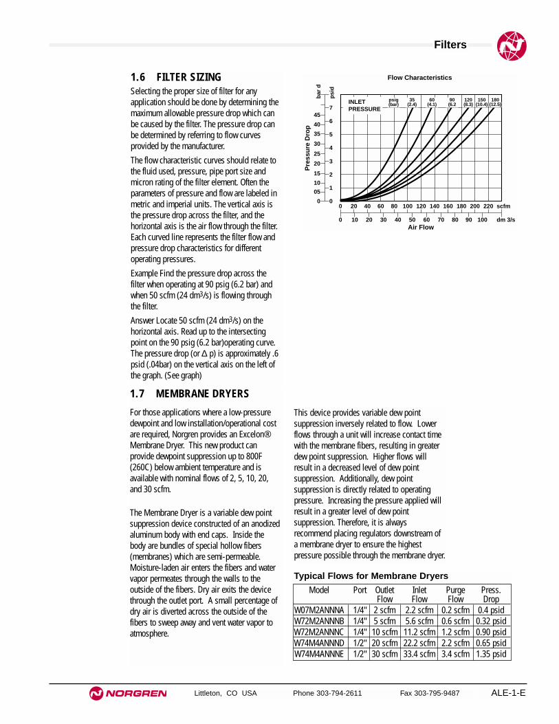
1.6 FILTER SIZINGSelecting the proper size of filter for anyapplication should be done by determining themaximum allowable pressure drop which canbe caused by the filter. The pressure drop canbe determined by referring to flow curvesprovided by the manufacturer.
The flow characteristic curves should relate tothe fluid used, pressure, pipe port size andmicron rating of the filter element. Often theparameters of pressure and flow are labeled inmetric and imperial units. The vertical axis isthe pressure drop across the filter, and thehorizontal axis is the air flow through the filter.Each curved line represents the filter flow andpressure drop characteristics for differentoperating pressures.
Example Find the pressure drop across thefilter when operating at 90 psig (6.2 bar) andwhen 50 scfm (24 dm3/s) is flowing throughthe filter.
Answer Locate 50 scfm (24 dm3/s) on thehorizontal axis. Read up to the intersectingpoint on the 90 psig (6.2 bar)operating curve.The pressure drop (or ∆ p) is approximately .6psid (.04bar) on the vertical axis on the left ofthe graph. (See graph)
00
0 10 20 30 40 50Air Flow
Flow Characteristics
60 70 80 90 100
20 40 60 80 100 120 140 160 180 200 220 scfm
dm 3/s
0
05
10
15
20
25
30
35
40
45
bar
d
psi
d
1
2
3
4
5
6
7
Pre
ssu
re D
rop
180(12.5)
150(10.4)
120(8.3)
90(6.2
60(4.1)
35(2.4)
psig(bar)INLET
PRESSURE
1.7 MEMBRANE DRYERS
For those applications where a low-pressuredewpoint and low installation/operational costare required, Norgren provides an Excelon®Membrane Dryer. This new product canprovide dewpoint suppression up to 800F(260C) below ambient temperature and isavailable with nominal flows of 2, 5, 10, 20,and 30 scfm.
The Membrane Dryer is a variable dew pointsuppression device constructed of an anodizedaluminum body with end caps. Inside thebody are bundles of special hollow fibers(membranes) which are semi-permeable.Moisture-laden air enters the fibers and watervapor permeates through the walls to theoutside of the fibers. Dry air exits the devicethrough the outlet port. A small percentage ofdry air is diverted across the outside of thefibers to sweep away and vent water vapor toatmosphere.
This device provides variable dew pointsuppression inversely related to flow. Lowerflows through a unit will increase contact timewith the membrane fibers, resulting in greaterdew point suppression. Higher flows willresult in a decreased level of dew pointsuppression. Additionally, dew pointsuppression is directly related to operatingpressure. Increasing the pressure applied willresult in a greater level of dew pointsuppression. Therefore, it is alwaysrecommend placing regulators downstream ofa membrane dryer to ensure the highestpressure possible through the membrane dryer.
Model Port Outlet Inlet Purge Press.Flow Flow Flow Drop
W07M2ANNNA 1/4" 2 scfm 2.2 scfm 0.2 scfm 0.4 psidW72M2ANNNB 1/4" 5 scfm 5.6 scfm 0.6 scfm 0.32 psidW72M2ANNNC 1/4" 10 scfm 11.2 scfm 1.2 scfm 0.90 psidW74M4ANNND 1/2" 20 scfm 22.2 scfm 2.2 scfm 0.65 psidW74M4ANNNE 1/2" 30 scfm 33.4 scfm 3.4 scfm 1.35 psid
Typical Flows for Membrane Dryers

Filters
Littleton, CO USA Phone 303-794-2611 Fax 303-795-9487ALE-1-F
Malfunction Possible cause Remedy
Excessive pressure drop. Micron rating of element to small Use larger micron element size for application.
Filter element blocked. 1. Clean element (notcoalescing element). Note: Some residual contamination will remain.
2. Replace with new element.
Flow requirement greater than Use larger filter.filter capacity.
Dirt passing through filter. Element seals missing or Replace sealdefective. (N.B. Seals not 2. Tighten element.required on some units).
Damaged element. Replace element.
Water passing through filter. Water level in bowl above Drain water.baffle.
Flow capacity of filter Maintain flow within capacityexceeded. of filter or change to filter
capable of handling desired flows.
Crazing of Polycarbonate bowl Bowl has been cleaned with Replace bowl.or milky appearance. incompatible fluid. (Clean only in clean warm water and soap.)
Bowl is being used in an area Replace bowl.containing fumes or vapors Eliminate source of problem orincompatible with polycarbonate. convert from plastic to metal bowls.
Compressor oil vapor may be Replace bowl.causing problem. Eliminate source of problem or
convert from plastic to metal bowls.
Air intake to compressor may Replace bowl.contain fumes or vapor Eliminate source of problem or
incompatible with polycarbonate.convert from plastic to metal bowls.
Water beyond the filter Inlet air has a high temperature Fit dryer, pre-cool air or fitand as it cools downstream, filter immediately prior to application.moisture condenses to water.
1.7 SIMPLE FILTER TROUBLESHOOTING

Rating Filter Elements and ISO Standard 8573-1
Littleton, CO USA Phone 303-794-2611 Fax 303-795-9487 ALE-1-G
Absence of an Industrial Standard for RatingPneumatic Filter Elements There is not an industry wide standard for establishing the micronrating of pneumatic filter elements. Standards by various industryassociations, including the National Fluid Power Association(NFPA) and International Standard Organization (ISO), are indiscussion. In the absence of an industry standard, somemanufacturers of pneumatic filters make claims concerning themicron rating of their so called “standard” element which can notbe substantiated and are probably not valid.
Norgren’s Method of Rating and Testing Pneumatic Filter Elements Norgren particle removal filter elements are rated by the size ofthe particle they will trap (i.e., a 40-micron element will removeparticles 40-microns and larger). Norgren tests filter elements byusing standard coarse and fine test dusts of known particle sizedistribution. Coarse dust consists of 12% particles smaller than 5-microns; fine grain dust consists of 39% particles smaller than5-microns. Test results show that a Norgren filter element rated at40-microns actually removes over 98% of particles 5-microns andlarger.
How to Size a Filter ElementThe downstream equipment being protected determines themicron rating of the filter element. Industrial tools, such as airhammers and drills, typically require only a 40-micron element.Air operated instruments and small, high speed tools typicallyrequire a 5-micron element. Always consult the equipmentmanufacturer for filtration requirements.
Generally, the smaller the micron rating of the element,● the higher the pressure drop across the filter,● the shorter the element service life.
Therefore, the use of a 5-micron element where a 40-micron isadequate penalizes the customer in increased pressure lossesand frequent down time for changing or cleaning the filter element.
ISO Standard 8573-1. Compressed Airfor General Use Contaminant’s found in industrial compressedair systems include solid particles, water, andoil. ISO 8573-1:1991 provides a simple methodof classifying these contaminant’s. A qualityclass required for a particular application canbe defined by listing, in order, the classrequired for solids, water, and oil.
Examples:Air of Quality Class 2.2.2 is filtered to 1µmsolid particle size, dried to -40°F (-40°C)pressure dewpoint, and filtered to an oilconcentration of 0.1mg/m3.
Air of Quality Class 5.3.4 is filtered to 40µmsolid particle size, dried to -4°F (-20°C)pressure dewpoint, and filtered to an oilconcentration of 5mg/m3 .
When a class for a particular contaminantsolid, water, or oil is not specified, the numberdesignating the class is replaced with ahyphen.
Example: Air of Quality Class 1.–.1 does notspecify the pressure dewpoint.
Table 1. Summary of ISO 8573-1:1991 AirQuality Classes *
Solid Water OilParticle Maximum Maximum
Maximum Pressure RemainingQuality Size Dewpoint Oil ContentClass µm °F (°C) mg/m3 ** (ppm)
1 0.1 -94 (-70) 0.01 (.0084)2 1 -40 (-40) 0.1 (.084)3 5 -4 (-20) 1 (.84)4 15 38 (3) 5 (4.2)5 40 45 (7) 25 (21)6 — 50 (10) —
* See ISO standard 8573-1 for completeinformation.** At 1 bar absolute pressure.


Littleton, CO USA Phone 303-794-2611 Fax 303-795-9487 ALE-1-1
Section 1
F07 Miniature General Purpose Filter 1/8" and 1/4" Ports . . . . . . . . .ALE-1-2F72G Excelon General Purpose Filter 1/4" and 3/8" Ports . . . . . . . .ALE-1-4F73G Excelon General Purpose Filter 1/4" to 1/2" Ports . . . . . . . . . .ALE-1-6F74G Excelon General Purpose Filter 1/4" to 3/4" Ports . . . . . . . . . .ALE-1-8F64G Olympian Plus General Purpose Filter 1/4" to 3/4" Ports . . . .ALE-1-10F68G Olympian Plus General Purpose Filter 3/4" to 1-1/2" Ports . .ALE-1-12F17 General Purpose Filter 3/4" to 1-1/2" Ports . . . . . . . . . . . . . . . .ALE-1-14F18 General Purpose Filter 1-1/2" and 2" Ports . . . . . . . . . . . . . . . .ALE-1-16
General Purpose FiltersCompressed air, generalpurpose filters are available inmodular or inline models, in portsizes from 1/8" to 2".
F07 F72G F73G F74G F64G
F17
F68
F18
Product available 1stquarter of 2001

See Section ALE-25 for Accessories
Littleton, CO USA Phone 303-794-2611 Fax 303-795-9487
F07
● Compact design
● Protects air operated devices by removing liquid andsolid contaminants
● Screw-on bowl reduces maintenance time
● Can be disassembled without the use of tools orremoval from the air line
Miniature Series 07 General Purpose Filter 1/8" and 1/4" Port Sizes
ALE-1-2
Port Size Model Numbers Flow scfm (dm3/s) * Weight lbs (kg)1/8" F07-100-A1TA 19 (9) 0.28 (0.13)1/4" F07-200-A1TA 24 (11.5) 0.28 (0.13)
Ordering Information. Models listed include PTF threads, automatic drain, transparent bowl and 5 µm element.
* Approximate flow at 90 psig (6.3 bar) inlet pressure and 5 psig (0.35 bar) pressure drop.
Alternative Models
Port Size Substitute1/8" 11/4" 2
Threads SubstitutePTF AISO Rc taper BISO G parallel G
Option SubstituteNot applicable 0
Bowl SubstituteTransparent TMetal M
Option SubstituteNot applicable 0 Element Substitute
5 µm 140 µm 3
Drain SubstituteAutomatic AManual M
- ★★★ ★★ ★ -0 ★F 7
ISO Symbols
Auto Drain Manual Drain

F07 General Purpose Filters
Littleton, CO USA Phone 303-794-2611 Fax 303-795-9487 ALE-1-3
Technical DataFluid: Compressed airMaximum pressure:
Transparent bowl: 150 psig (10 bar)Metal bowl: 250 psig (17 bar)
Operating temperature:*Transparent bowl: -30° to 125°F (-34° to 50°C)Metal bowl: -30° to 175°F (-34° to 80°C)
* Air supply must be dry enough to avoid ice formation at temperatures below 35°F (2°C)
Particle removal: 5 µm or 40 µm filter elementAir quality: Within ISO 8573-1, Class 3 and Class 5 (particulates)Typical flow at 90 psig (6.3 bar) inlet pressure at 5 psig (0.35 bar) pressure drop:
1/8" Ports, 5 µm element: 19 scfm (9 dm3/s) 1/4" Ports, 5 µm element: 24 scfm (11.5 dm3/s)
Nominal bowl size: 1 fluid ounce (31 ml)Drain connection: 1/8" pipe threadAutomatic drain operation: Spitter type drain operates momentarily when a rapid
change in air flow occurs or when the supply pressure is reduced.Materials
Body: ZincBowl
Transparent: PolycarbonateMetal: Zinc (without sight glass)
Element: Sintered polypropyleneElastomers: Neoprene & nitrile
Typical Performance Characteristics
FLOW CHARACTERISTICS
0 2 4 6 8 10 dm3/s
AIR FLOW
0 4 8 12 16 20 scfm
0.8
0.6
0.4
0.2
0
PR
ES
SU
RE
DR
OP
bar
d
10
8
6
4
2
0
psi
d
PORT SIZE: 1/4" 5 µm ELEMENT
INLET PRESSURE: psig (bar)25
(1.8)60
(4.0)40
(2.8) 90(6.3)
120(8)
180(12)
150(10)
0.157 (4) Dia †0.5 (13) Deep †
Automatic DrainManual Drain
1.45
(37
)
0.91
(23)
0.73(19)
0.91(23)
1.63 (42)
6.07
(15
4) *
0.38
(10
)
4.10
(10
4)
6.22
(15
8) *
*
4.25
(10
8)
0.38
(10
)
** Minimum clearance to remove bowl.† Mounting holes.
Service KitsItem Type Part number
Service kit5 µm element 3652-1740 µm element 3652-18
Replacement drainsManual 773-03Automatic 3654-02
Service kit includes element, element gasket, and bowl o-ring.
All Dimensions in Inches (mm)

See Section ALE-25 for Accessories
Littleton, CO USA Phone 303-794-2611 Fax 303-795-9487
F72G
● Excelon design allows in-line or modular installation
● High efficiency water and particle removal
● Quick release bayonet bowl
● Highly visible, prismatic liquid level indicator lens onmetal bowls
● Optional service indicator turns from green to redwhen the filter element needs to be replaced
● Optional electrical service indicator also available
● Modular installations with Excelon 72, 73, and 74series can be made to suit particular applications
Excelon 72 General Purpose Filter1/4" and 3/8" Port Sizes
ALE-1-4
Ordering Information. Models listed include PTF threads, automatic drain, long transparent bowl without guard, 40 µm element. Models do notinclude the service life indicator.
† Typical flow with a 40µm element at 90 psig (6.3 bar) inlet pressure and 5 psig (0.35 bar) pressure drop.
Port Size Model Flow† scfm (dm3/s) Weight lb (kg)1/4" F72G-2AN-AL3 55 (26) 1.15 (0.52)3/8" F72G-3AN-AL3 55 (26) 1.15 (0.52)
* Supplied in long bowl options only
F 7 2 -G ★ ★ - ★★ ★ ★
Port Size Substitute1/4" 23/8" 3
Threads SubstitutePTF AISO Rc taper BISO G parallel G
Drain Substitute1/4 turn manual QSemi automatic SAuto drain* A
Element Substitute5 µm 125 µm 240 µm 3
Service Life Indicator SubstituteWith (visual) DWith (electrical) EWithout N
Alternative Models
Bowl SubstituteShort metal with liquid level indicator DLong metal with liquid level indicator EShort transparent without guard TLong transparent without guard LLong transparent with guard W
ISO Symbols
Auto Drain Manual Drain

F72G General Purpose Filters
Littleton, CO USA Phone 303-794-2611 Fax 303-795-9487 ALE-1-5
Technical DataFluid: Compressed airMaximum pressure:
Transparent bowl: 150 psig (10 bar)Metal bowl:
Manual or semi automatic drain: 250 psig (17 bar)Automatic drain: 150 psig (10 bar)
Operating temperature*:Transparent bowl: -30° to 125°F (-34° to 50°C)Metal bowl: -30° to 150°F (-34° to 65°C)
* Air supply must be dry enough to avoid ice formation at temperatures below 35°F (2°C).Particle removal: 5 µm, 25 µm or 40 µm. Within ISO 8573-1, Class 3 and Class 5Typical flow at 90 psig (6.3 bar) inlet pressure and 5 psig (0.35 bar) pressure drop:
5 µm element: 47 scfm (22 dm3/s)40 µm element: 55 scfm (26 dm3/s)
Manual drain connection: Will fit 1/8-27 and 1/8-28 pipe thread.Semi automatic drain connection: Push on 5/16" (8 mm) ID tubeSemi automatic drain operating conditions (pressure operated):
Bowl pressure required to close drain: Greater than 1.5 psig (0.1 bar)Bowl pressure required to open drain: Less than 1.5 psig (0.1 bar) Minimum air flow required to close drain: 1 scfm (0.5 dm3/s)Manual operation: Lift stem to drain bowl
Automatic drain connection:Will fit 1/8-27 and 1/8-28 pipe thread. - Flexible tubewith 3/16" (5mm) minimum I.D. can be connected to the automatic drain. Drainmay fail to operate if the tube I.D. is less than 3/16" (5mm). Avoid restrictions inthe tube.
Automatic drain operating conditions (float operated):Bowl pressure required to close drain: Greater than 5 psig (0.35 bar) Bowl pressure required to open drain: Less than 3 psig (0.2 bar)Minimum air flow required to close drain: 0.2 scfm (0.1 dm3/s)Manual operation: Depress pin inside drain outlet to drain bowl
Nominal bowl size:Short bowl: 1.9 fluid ounce (56 ml)Long bowl: 2.2 fluid ounce (65 ml)
MaterialsBody: ZincBowl
Transparent: PolycarbonateGuard for transparent bowl: ZincMetal: Zinc
Metal bowl liquid level indicator lens:Transparent nylon
Element: Sintered polypropyleneElastomers: Neoprene and nitrile
Typical Performance CharacteristicsFLOW CHARACTERISTICS
0 10 20 30 40 50 dm3/s
AIR FLOW
0 20 40 60 80 100 120 scfm
PR
ES
SU
RE
DR
OP
0.8
0.6
0.4
0.2
0
bar
d
10
8
6
4
2
0
psi
d
PORT SIZE: 1/4" 5 µm ELEMENT
INLET PRESSURE - psig (bar g)
36(2.5)
58(4.0)
91(6.3)
116(8.0)
150(10.0)
FLOW CHARACTERISTICS
0 10 20 30 40 50 dm3/sAIR FLOW
0 20 40 60 80 100 120 scfm
PR
ES
SU
RE
DR
OP
0.8
0.6
0.4
0.2
0
bar
d
10
8
6
4
2
0 p
sid
PORT SIZE: 1/4" 40 µm ELEMENT
INLET PRESSURE - psig (bar g)
36(2.5)
58(4.0)
91(6.3)
116(8.0)
150(10.0)
1.97 (50)
1.89
(48
)
Short Bowl with 1/4 Turn Manual Drain
5.27
(13
4)
7.27
(18
5) †
2.10
(53
)
0.75
(19)
Service LifeIndicator
Short Bowl with Semi auto Drain
6.93
(17
6)
8.94
(22
7) †
Long Bowl with Automatic Drain
5.51
(14
0)
7.52
(19
1) †
Long Bowl with Semi auto Drain
7.48
(19
0)
9.84
(25
0) †
Long Bowl with 1/4 Turn Manual Drain
5.83
(14
8)
7.83
(19
9) †
(Top)
Service KitsItem Type Part NumberService kit Seal and gasket 4380-500
5 µm 5925-03Elements 25 µm 5925-01
40 µm 5925-02Liquid level lens kit Prismatic 4380-030
1/4 turn manual 619-50Replacement drains Semi automatic 5379-RK
Automatic 4000-50RService kit includes drain and bowl o-rings.
† Minimum clearance required to remove bowl.
All Dimensions in Inches (mm)

See Section ALE-25 for Accessories
Littleton, CO USA Phone 303-794-2611 Fax 303-795-9487
F73G
● Excelon design allows in-line or modular installation
● Quick release bayonet bowl
● Highly visible, prismatic liquid level indicator lens
● Optional mechanical service indicator turns fromgreen to red when the filter element needs to bereplaced
● Optional electrical service indicator provideselectrical output when the filter element needs to bereplaced
● Modular installations with Excelon 72, 73, and 74series can be made to suit particular applications
Excelon 73 General Purpose Filter1/4", 3/8", 1/2" Port Sizes
ALE-1-6
Ordering information. Models listed include PTF threads, automatic drain, metal bowl with liquid level indicator, and a 40 µm element.
* Typical flow with a 40 µm element at 90 psig (6.3 bar) inlet pressure and 5 psig (0.35 bar) pressure drop.
Alternative ModelsF 7 3 -G ★ ★ - ★★ ★ ★
Threads SubstitutePTF AISO Rc taper BISO G parallel G
Service Indicator SubstituteWith electrical service indicator * EWith mechanical service indicator DWithout N
Drain SubstituteAutomatic AManual, 1⁄4 turn Q
Element Substitute5 µm 125 µm 240 µm 3
Bowl SubstituteMetal with liquid level indicator DTransparent with guard PTransparent T
Port Size Substitute1/4" 23/8" 31/2" 4
Port Size Model Flow* scfm (dm3/s) Weight lb (kg)1/4" F73G-2AN-AD3 53 (25) 1.1 (0.50)3/8" F73G-3AN-AD3 65 (31) 1.1 (0.50)1/2" F73G-4AN-AD3 69 (33) 1.1 (0.50)
ISO Symbols
Auto Drain Manual Drain

F73G General Purpose Filters
Littleton, CO USA Phone 303-794-2611 Fax 303-795-9487 ALE-1-7
All Dimensions in Inches (mm)
Technical DataFluid: Compressed airMaximum pressure:
Transparent bowl: 150 psig (10 bar)Metal bowl: 250 psig (17 bar)
Operating temperature*:Transparent bowl: -30° to 125°F (-34° to 50°C)Metal bowl: -30° to 175°F (-34° to 80°C)
* Air supply must be dry enough to avoid ice formation at temperatures below 35°F (2°C).Particle removal: 5 µm, 25 µm, or 40 µm filter elementAir quality: Within ISO 8573-1, Class 3 and Class 5 (particulates)Typical flow with a 40 µm element at 90 psig (6.3 bar) inlet pressure and 5 psig(0.35 bar) pressure drop: 65 scfm (31 dm
3/s)
Manual drain connection: Will fit 1/8-27 and 1/8-28 pipe thread.Automatic drain connection: Will fit 1/8-27 and 1/8-28 pipe thread. - Flexible tube
with 3/16" (5mm) minimum I.D. can be connected to the automatic drain. Drainmay fail to operate if the tube I.D. is less than 3/16" (5mm). Avoid restrictions inthe tube.
Automatic drain operating conditions (float operated):Bowl pressure required to close drain: Greater than 5 psig (0.3 bar)Bowl pressure required to open drain: Less than 3 psig (0.2 bar)Minimum air flow required to close drain: 0.2 scfm (0.1 dm3/s) Manual operation: Depress pin inside drain outlet to drain bowl
Nominal bowl size: 3.5 fluid ounce (0.1 liter)Materials
Body: AluminumBowl
Transparent: PolycarbonateTransparent with guard: Polycarbonate, steel guardMetal: AluminumMetal bowl liquid level indicator lens: Transparent nylon
Element: Sintered polypropyleneElastomers: Neoprene and nitrile
PR
ES
SU
RE
DR
OP 0.6
0.4
0.2
0
bar
d
10
8
6
4
2
0
psi
d
PORT SIZE: 3/8"ELEMENT: 5 µm
36(2.5)
58(4.0)
150(10.0)
90(6.3)
116(8.0)
INLET PRESSURE: psig (bar)
0 10 20 30 40 50 dm3/s
AIR FLOW
0 20 40 60 80 100 scfm
FLOW CHARACTERISTICS
Typical Performance Characteristics
PR
ES
SU
RE
DR
OP 0.6
0.4
0.2
0
bar
d
10
8
6
4
2
0 p
sid
PORT SIZE: 3/8"ELEMENT: 40 µm
36(2.5)
58(4.0)
150(10.0)
90(6.3)
116(8.0)
INLET PRESSURE: psig (bar)
0 10 20 30 40 50 dm3/s
0 20 40 60 80 100 scfm
AIR FLOW
FLOW CHARACTERISTICS
** Minimum clearance required to remove bowl.
6.15
(15
6)
1/4 Turn Manual Drain
8.50
(21
6) *
* 1.00
(25
)
2.36
(60
)
Automatic Drain
OptionalMechanicalServiceIndicator
5.80
(14
7)
8.15
(20
7) *
*
2.68 (68)
2.45
(62
)1.22
(31
)
Service kit includes automatic drain seal and bowl seal.
Service KitsItem Type Part NumberService kit Seal & Gasket 4380-600
Replacement elements5 µm 4438-0125 µm 4438-0240 µm 4438-03
Liquid level lens kit Prismatic 4380-020
Replacement drainsAutomatic 4000-51RManual quarter turn 619-50

See Section ALE-25 for Accessories
Littleton, CO USA Phone 303-794-2611 Fax 303-795-9487
F74G
● Excelon design allows in-line or modular installation
● Quick release bayonet bowl
● Highly visible, prismatic liquid level indicator lens
● Optional mechanical service indicator turns fromgreen to red when the filter element needs to bereplaced
● Optional electrical service indicator provideselectrical output when the filter element needs to bereplaced
● Modular installations with Excelon 72, 73, and 74series can be made to suit particular applications
Excelon 74 General Purpose Filter3/8", 1/2", 3/4" Port Sizes
ALE-1-8
Ordering information. Models listed include PTF threads, automatic drain, metal bowl with liquid level indicator, and a 40 µm element.
* Typical flow with a 40 µm element at 90 psig (6.3 bar) inlet pressure and 5 psig (0.35 bar) pressure drop.
Alternative ModelsF 7 4 -G ★ ★ - ★★ ★ ★
Threads SubstitutePTF AISO Rc taper BISO G parallel G
Service Life Indicator SubstituteWith (visual) DWith (electrical) EWithout N
Drain SubstituteAutomatic AManual, 1⁄4 turn Q
Element Substitute5 µm 125 µm 240 µm 3
Bowl SubstituteMetal with liquid level indicator DTransparent with guard P
Port Size Substitute3/8" 31/2" 43/4" 6
Port Size Model Flow* scfm (dm3/s) Weight lb (kg)3/8" F74G-3AN-AD3 112 (53) 1.82 (0.83)1/2" F74G-4AN-AD3 140 (66) 1.79 (0.81)3/4" F74G-6AN-AD3 140 (66) 1.75 (0.79)
ISO Symbols
Auto Drain Manual Drain
F74G General Purpose Filters
Littleton, CO USA Phone 303-794-2611 Fax 303-795-9487 ALE-1-9
All Dimensions in Inches (mm)
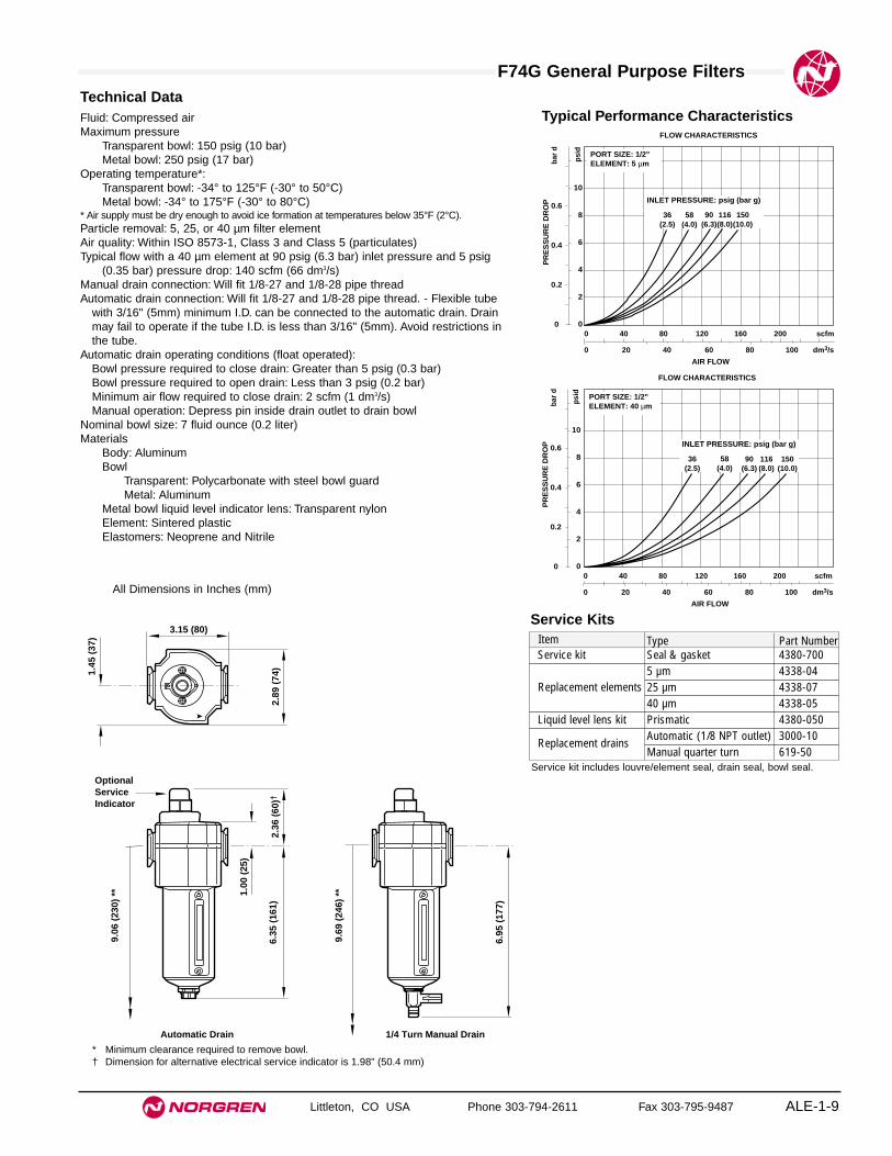
Technical DataFluid: Compressed airMaximum pressure
Transparent bowl: 150 psig (10 bar)Metal bowl: 250 psig (17 bar)
Operating temperature*:Transparent bowl: -34° to 125°F (-30° to 50°C)Metal bowl: -34° to 175°F (-30° to 80°C)
* Air supply must be dry enough to avoid ice formation at temperatures below 35°F (2°C).Particle removal: 5, 25, or 40 µm filter elementAir quality: Within ISO 8573-1, Class 3 and Class 5 (particulates)Typical flow with a 40 µm element at 90 psig (6.3 bar) inlet pressure and 5 psig
(0.35 bar) pressure drop: 140 scfm (66 dm3/s) Manual drain connection: Will fit 1/8-27 and 1/8-28 pipe threadAutomatic drain connection: Will fit 1/8-27 and 1/8-28 pipe thread. - Flexible tube
with 3/16" (5mm) minimum I.D. can be connected to the automatic drain. Drainmay fail to operate if the tube I.D. is less than 3/16" (5mm). Avoid restrictions inthe tube.
Automatic drain operating conditions (float operated):Bowl pressure required to close drain: Greater than 5 psig (0.3 bar)Bowl pressure required to open drain: Less than 3 psig (0.2 bar)Minimum air flow required to close drain: 2 scfm (1 dm3/s) Manual operation: Depress pin inside drain outlet to drain bowl
Nominal bowl size: 7 fluid ounce (0.2 liter)Materials
Body: AluminumBowl
Transparent: Polycarbonate with steel bowl guardMetal: Aluminum
Metal bowl liquid level indicator lens: Transparent nylonElement: Sintered plasticElastomers: Neoprene and Nitrile
Typical Performance Characteristics
PR
ES
SU
RE
DR
OP 0.6
0.4
0.2
0
bar
d
10
8
6
4
2
0
psi
d
36(2.5)
58(4.0)
150(10.0)
90(6.3)
116(8.0)
INLET PRESSURE: psig (bar g)
0 20 40 60 80 100 dm3/s
AIR FLOW
0 40 80 120 160 200 scfm
PORT SIZE: 1/2"ELEMENT: 5 µm
FLOW CHARACTERISTICS
PR
ES
SU
RE
DR
OP 0.6
0.4
0.2
0
bar
d
10
8
6
4
2
0 p
sid
PORT SIZE: 1/2"ELEMENT: 40 µm
36(2.5)
58(4.0)
150(10.0)
90(6.3)
116(8.0)
INLET PRESSURE: psig (bar g)
0 20 40 60 80 100 dm3/s
AIR FLOW
0 40 80 120 160 200 scfm
FLOW CHARACTERISTICS
6.95
(17
7)
1/4 Turn Manual Drain
9.69
(24
6) *
*
3.15 (80)
2.36
(60
)†
1.00
(25
)
2.89
(74
)1.45
(37
)
Automatic Drain
OptionalServiceIndicator
6.35
(16
1)
9.06
(23
0) *
*
* Minimum clearance required to remove bowl.† Dimension for alternative electrical service indicator is 1.98" (50.4 mm)
Item Type Part NumberService kit Seal & gasket 4380-700
Replacement elements5 µm 4338-0425 µm 4338-0740 µm 4338-05
Liquid level lens kit Prismatic 4380-050
Replacement drainsAutomatic (1/8 NPT outlet) 3000-10Manual quarter turn 619-50
Service kit includes louvre/element seal, drain seal, bowl seal.
Service Kits

See Section ALE-25 for Accessories
Littleton, CO USA Phone 303-794-2611 Fax 303-795-9487
F64G
● Olympian Plus plug in design
● High efficiency water and particle removal
● Quick release bayonet bowl
● High visibility prismatic sight glass
● Optional service indicator
Olympian Plus General Purpose Filter1/4", 3/8", 1/2", 3/4" Port Sizes
ALE-1-10
Ordering Information. Models listed include PTF threads, yoke, automatic drain, metal bowl, 40 µm element.Models do not include the service life indicator.
† Typical flow with a 40 µm element at 90 psig (6.3 bar) inlet pressure and a 5 psig (0.35 bar) pressure drop.
Port Size Model Flow† scfm (dm3/s) Weight lb (kg)1/4" F64G-2AN-AD3 59 (28) 3.13 (1.42)3/8" F64G-3AN-AD3 118 (56) 3.13 (1.42)1/2" F64G-4AN-AD3 125 (59) 2.91 (1.32)3/4" F64G-6AN-AD3 125 (59) 3.79 (1.72)
F 6 4 -G ★ ★ - ★★ ★ ★
Port Size Substitute1/4" 23/8" 31/2" 43/4" 6No yoke N
Threads SubstitutePTF AISO Rc taper BISO G parallel GNo yoke N Drain Substitute
Auto drain AManual, 1/4 turn Q
Element Substitute5 µm 125 µm 240 µm 3
Service Life Indicator SubstituteWith (visual) DWith (electrical) EWithout N
Alternative Models
Bowl SubstituteMetal with liquid level indicator DTransparent with guard P
ISO Symbols
Auto Drain Manual Drain

F64G General Purpose Filters
Littleton, CO USA Phone 303-794-2611 Fax 303-795-9487 ALE-1-11
Technical DataFluid: Compressed airMaximum pressure
Guarded transparent bowl: 150 psig (10 bar)Metal bowl: 250 psig (17 bar)
Operating temperature*:Guarded transparent bowl: -30° to 125°F (-34° to 50°C)Metal bowl: -30° to 175°F (-34° to 80°C)
* Air supply must be dry enough to avoid ice formation at temperatures below 35°F (2°C).Partical removal: 5 µm, 25 µm or 40 µm. Within ISO 8573-1, Class 3 and Class 5Typical flow with 40 µm element at 90 psig (6.3 bar) inlet pressure and 5 psig
(0.35 bar) pressure drop: 125 scfm (59 dm3/s)Manual drain connection: Will fit 1/8-27 and 1/8-28 pipe thread.Automatic drain connection: Will fit 1/8-27 and 1/8-28 pipe thread. - Flexible tube
with 3/16" (5mm) minimum I.D. can be connected to the automatic drain. Drainmay fail to operate if the tube I.D. is less than 3/16" (5mm). Avoid restrictions inthe tube.
Automatic drain operating conditions (float operated):Bowl pressure required to close drain: Greater than 5 psig (0.3 bar)Bowl pressure required to open drain: Less than 3 psig (0.2 bar)Minimum air flow required to close drain: 2 scfm (1 dm3/s) Manual operation: Depress pin inside drain outlet to drain bowl
Nominal bowl size: 7 fluid ounce (0.2 liter)Materials
Body: ZincYoke: ZincMetal bowl: AluminumStandard metal bowl prismatic liquid level indicator lens: GrilamidOptional metal bowl sight glass: PyrexOptional transparent bowl: PolycarbonateElement: Sintered plasticElastomers: Synthetic rubber
Typical Performance Characteristics
FLOW CHARACTERISTICS
0 20 40 60 80 100 dm3/s
AIR FLOW
0 40 80 120 160 200 240 scfm
PR
ES
SU
RE
DR
OP
0.8
0.6
0.4
0.2
0
bar
d
10
8
6
4
2
0
psi
d
PORT SIZE: 1/2" 40 µm ELEMENT
INLET PRESSURE - psig (bar g)
36(2.5)
58(4.0)
91(6.3)
116(8.0)
150(10.0)
* 6.18" (157 mm) for 3/4" models
† Minimum clearance required to remove bowl.
Automatic Drain
8.54
(21
7)†
4.13 (105)*
1.46
(37)
2.91
(74)
OptionalServiceIndicator
1.46
(37)
6.45
(16
4)2.
32 (
59)
7.05
(17
9)
1/4 Turn Manual Drain
9.14
(23
2)†
Service KitsItem Type Part NumberService kit Seal and gasket 4380-200
5 µm 4338-01Elements 25 µm 4338-99
40 µm 4338-02
Liquid level lens kitPrismatic 4380-040Pyrex 4380-041
Replacement drainsAutomatic 3000-10Manual 684-84
Service kit includes port seals, louver o-ring, bowl o-ring and drain gasket.All Dimensions in Inches (mm)

Port Size Model Weight lb (kg)3/4" F68-6AN-AR3 6.04 (2.72)1" F68-8AN-AR3 5.78 (2.60)1-1/4" F68-AAN-AR3 6.00 (2.70)1-1/2" F68-BAN-AR3 5.64 (2.54)
Littleton, CO USA Phone 303-794-2611 Fax 303-795-9487
F68G
● Olympian plug in design
● High efficiency water and particle removal
Olympian Filter3/4", 1", 1-1/4", 1-1/2" Port Sizes
ALE-1-12
Ordering Information. Models listed include PTF threads, automatic drain, 50 µm element and 0.5 liter bowl.
F 6 8 -G ★ ★ - ★★ ★ ★
Drain SubstituteManual MAuto drain AClosed bowl E
Element Substitute5 µm 125 µm 250 µm 3
Service Life Indicator SubstituteWith mechanical service indicator DWith electrical service indicator** EWithout N
Alternative Models
Bowl Substitute1 quart (1 liter) without liquid level indicator C1 pint (0.5 liter) without liquid level indicator M1 pint (0.5 liter) with liquid level indicator R1 quart (1 liter) with liquid level indicator U
Threads SubstitutePTF AISO Rc taper BISO G parallel GNone N
Port Size Substitute3/4" 61" 81-1/4" A1-1/2" BNone N
** See Accessories for description and specifications.
ISO Symbols
Auto Drain Manual Drain
68 Series products are available 1st quarter of 2001. Visit www.norgren.com for the latestdata on this series.

F68G General Purpose Filters
Littleton, CO USA Phone 303-794-2611 Fax 303-795-9487 ALE-1-13
All Dimensions in Inches (mm)
Technical DataFluid: Compressed airMaximum pressure
Metal bowl: 250 psig (17 bar)Operating temperature*
Metal bowl: 0° to 175°F (-20° to 80°C)
* Air supply must bedry enough to avoidice formation attemperatures below35°F (2°C).Particle removal: 5,
25 or 50 µm.Air quality: Within
ISO 8573-1, Class 3 and Class 5 (particulates).Typical flow at 90 psig (6.3 bar) inlet pressure and a droop of 5 psig (0.35 bar):
50 µm element: 393 scfm (185 dm3/s) TBA from Lab TestAutomatic drain connection: Will fit 1/8-27 and 1/8-28 pipe thread. - Flexible tube
with 3/16" (5mm) minimum I.D. can be connected to the automatic drain. Drainmay fail to operate if the tube I.D. is less than 3/16" (5mm). Avoid restrictions inthe tube.
Automatic drain operating conditionsMinimum pressure: 10 psig (0.7 bar).Drain opens when bowl pressure drops below 3 psig (0.2 bar).Minimum air flow: 2 scfm (1 dm3/s) required to close drain.
Nominal bowl size:1 pint US (0.5 liter)
MaterialsBody: AluminumYoke: AluminumMetal bowl: AluminumSight glass: Pyrex
Typical Performance Characteristics
FLOW CHARACTERISTICS
0 50 100 150 200 250 dm3/s
AIR FLOW
0 100 200 300 400 500 600 scfm
PR
ES
SU
RE
DR
OP
0.8
0.6
0.4
0.2
0
bar
g
1
8
6
4
2
0
psi
g
UNPORTED 50 µm ELEMENT
INLET PRESSURE - psig (bar g)
36(2.5)
58(4.0)
91(6.3)
116(8.0)
150(10.0)
** For mechanical service indicator add 1.38" (35 mm). For electrical service indicator add 1.98" (50.4 mm)For closed bowl subtract 0.35" (9 mm) from auto drain dimension.
† Minimum clearance required to remove bowl.
0.5 liter, automatic drain 0,5 liter, manual drain 1 liter, automatic drain1 liter, manual drain
8.94
(22
7)**
8.43
(21
4)**
†
G1/8
1.73
(44
)
1.38
(35
)
9.21
(23
4)**
8.70
(22
1)**
†
1.73
(44
)
1.38
(35
)
12.2
8 (3
12)*
*
11.7
7 (2
99)*
*†
G1/8
1.73
(44
)
1.38
(35
)
2.13
(54
)
4.92 (125)
12.5
6 (3
19)*
*
12.0
5 (3
06)*
*†
1.73
(44
)
1.38
(35
)
Service KitsItem Type Part NumberService Kit 4380-300
Replacement 5 µm 5576-97
Elements 25 µm 5576-9850 µm 5576-99
Replacement 1 pint US (0.5 liter) 4380-060Sight Glass 1 quart US (1 liter) 4380-062Replacement Automatic 3000-97Drains Manual 684-84Service Life Mechanical 5797-50Indicators Electrical 4020-51R
Service kit Includes: ……TBA.
68 Series products are available 1st quarter of 2001. Visit www.norgren.com for the latestdata on this series.
See Section ALE-25 for Accessories
Littleton, CO USA Phone 303-794-2611 Fax 303-795-9487
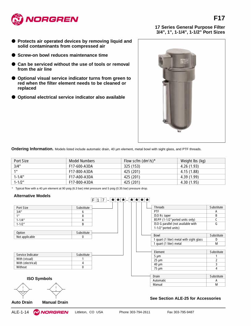
F17
● Protects air operated devices by removing liquid andsolid contaminants from compressed air
● Screw-on bowl reduces maintenance time
● Can be serviced without the use of tools or removalfrom the air line
● Optional visual service indicator turns from green tored when the filter element needs to be cleaned orreplaced
● Optional electrical service indicator also available
17 Series General Purpose Filter3/4", 1", 1-1/4", 1-1/2" Port Sizes
ALE-1-14
Ordering Information. Models listed include automatic drain, 40 µm element, metal bowl with sight glass, and PTF threads.
Port Size Model Numbers Flow scfm (dm3/s)* Weight lbs (kg)3/4" F17-600-A3DA 325 (153) 4.26 (1.93)1" F17-800-A3DA 425 (201) 4.15 (1.88)1-1/4" F17-A00-A3DA 425 (201) 4.39 (1.99)1-1/2" F17-B00-A3DA 425 (201) 4.30 (1.95)
* Typical flow with a 40 µm element at 90 psig (6.3 bar) inlet pressure and 5 psig (0.35 bar) pressure drop.
Alternative Models- ★★★ ★★ ★ -1 ★F 7
Drain SubstituteAutomatic AManual M
Bowl Substitute1 quart (1 liter) metal with sight glass D1 quart (1 liter) metal M
Port Size Substitute3/4" 61" 81-1/4" A1-1/2" B
Element Substitute5 µm 125 µm 240 µm 375 µm 4
Option SubstituteNot applicable 0
Service Indicator SubstituteWith (visual) 1With (electrical) 4Without 0
Threads SubstitutePTF AISO Rc taper BBSPP (1-1/2" ported units only) CISO G parallel (not available with G1-1/2" ported units)
ISO Symbols
Auto Drain Manual Drain
F17 General Purpose Filters
Littleton, CO USA Phone 303-794-2611 Fax 303-795-9487 ALE-1-15
All Dimensions in Inches (mm)
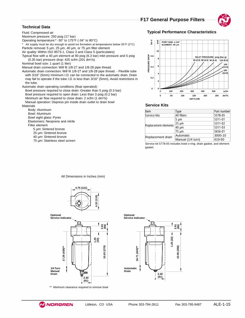
Technical DataFluid: Compressed airMaximum pressure: 250 psig (17 bar)Operating temperature:* -30° to 175°F (-34° to 80°C)* Air supply must be dry enough to avoid ice formation at temperatures below 35°F (2°C)Particle removal: 5 µm, 25 µm, 40 µm, or 75 µm filter elementAir quality: Within ISO 8573-1, Class 3 and Class 5 (particulates)Typical flow with a 40 µm element at 90 psig (6.3 bar) inlet pressure and 5 psig
(0.35 bar) pressure drop: 425 scfm (201 dm3/s)Nominal bowl size: 1 quart (1 liter)Manual drain connection: Will fit 1/8-27 and 1/8-28 pipe thread.Automatic drain connection: Will fit 1/8-27 and 1/8-28 pipe thread. - Flexible tube
with 3/16" (5mm) minimum I.D. can be connected to the automatic drain. Drainmay fail to operate if the tube I.D. is less than 3/16" (5mm). Avoid restrictions inthe tube.
Automatic drain operating conditions (float operated):Bowl pressure required to close drain: Greater than 5 psig (0.3 bar)Bowl pressure required to open drain: Less than 3 psig (0.2 bar)Minimum air flow required to close drain: 2 scfm (1 dm3/s) Manual operation: Depress pin inside drain outlet to drain bowl
MaterialsBody: AluminumBowl: AluminumBowl sight glass: PyrexElastomers: Neoprene and nitrileFilter element
5 µm: Sintered bronze25 µm: Sintered bronze40 µm: Sintered bronze75 µm: Stainless steel screen
Typical Performance Characteristics
PR
ES
SU
RE
DR
OP 0.6
0.4
0.2
0
bar
d
10
8
6
4
2
0
psi
d
PORT SIZE: 1-1/4"ELEMENT: 40 µm
0 50 100 150 200 250 dm3/s
AIR FLOW
0 100 200 300 400 500 scfm
36 (2.5) 58 (4.0) 90 (6.3)
INLET PRESSURE: psig (bar g)
150(10.0)
116 (8.0)
180(12.5)
4.32
(11
0)
4.75 (121)
OptionalService Indicator
1.25
(32
)2.
61(6
6)10
.06
(256
)
AutomaticDrain
2.40(61)
16.7
1 (4
24)*
*
OptionalService Indicator
1.25
(32)
2.61
(66)
10.6
3 (2
70)
1/4 TurnManualDrain
17.2
9 (4
39)*
*
2.40(61)
** Minimum clearance required to remove bowl
Service KitsItem Type Part numberService kits All filters 5578-05
5 µm 5311-01
Replacement elements25 µm 5311-0240 µm 5311-0375 µm 5656-01
Replacement drain Automatic 3000-10Manual (1/4 turn) 619-50
Service kit 5778-05 includes bowl o-ring, drain gasket, and elementgasket.

See Section ALE-25 for Accessories
Littleton, CO USA Phone 303-794-2611 Fax 303-795-9487
F18
● Protects air operated devices by removing liquid andsolid contaminants
● Highly visible, prismatic liquid level indicator lens
● Can be disassembled without removal from the airline
● Optional visual service indicator turns from green tored when the filter element needs to be cleaned orreplaced
● Optional electrical service indicator also available
18 Series General Purpose Filter1-1/2" and 2" Port Sizes
ALE-1-16
Alternative Models- ★★★ ★★ ★ -1 ★F 8
Drain SubstituteAutomatic AManual 1/4 turn M
Bowl SubstituteMetal with sight glass DMetal M
Port Size Substitute1-1/2" B2" C
Element Substitute5 µm 125 µm 240 µm 3100 µm 4
Option SubstituteNot applicable 0
Service Indicator SubstituteWithout 0With pneumatic 1With electrical 4
Ordering Information. Models listed include automatic drain, 40 µm element, metal bowl with sight glass, and PTF threads.
Port Size Model Numbers Flow scfm (dm3/s) * Weight lbs (kg)1-1/2" F18-B00-A3DA 1400 (661) 14.90 (6.76)2" F18-C00-A3DA 1400 (661) 14.65 (6.65)
* Typical flow with a 40 µm element at 90 psig (6.3 bar) inlet pressure and 5 psig (0.35 bar) pressure drop.
Threads SubstitutePTF AISO Rc taper BISO G parallel G
ISO Symbols
Auto Drain Manual Drain

F18 General Purpose Filters
Littleton, CO USA Phone 303-794-2611 Fax 303-795-9487 ALE-1-17
All Dimensions in Inches (mm)
Technical DataFluid: Compressed airMaximum pressure: 250 psig (17 bar)Operating temperature*: -30° to 175°F (-34° to 80°C)
* Air supply must be dry enough to avoid ice formation at temperatures below 35°F (2°C).Particle removal: 5 µm, 25 µm, 40 µm or 100 µm filter elementAir quality: Within ISO 8573-1, Class 3 and Class 5 (particulates)Typical flow with a 40 µm element at 90 psig (6.3 bar) inlet pressure and 5 psig
(0.35 bar) pressure drop: 1300 scfm (614 dm3/s)Nominal bowl size: 7 fluidounce (0.2 liter)
Manual drain connection: Will fit 1/8-27 and 1/8-28 pipe thread.Automatic drain connection: Will fit 1/8-27 and 1/8-28 pipe thread. - Flexible tube
with 3/16" (5mm) minimum I.D. can be connected to the automatic drain. Drainmay fail to operate if the tube I.D. is less than 3/16" (5mm). Avoid restrictions inthe tube.
Automatic drain operating conditions (float operated):Bowl pressure required to close drain: Greater than 5 psig (0.3 bar)Bowl pressure required to open drain: Less than 3 psig (0.2 bar)Minimum air flow required to close drain: 2 scfm (1 dm3/s) Manual operation: Depress pin inside drain outlet to drain bowl
MaterialsBody: AluminumIntermediate body: AluminumBowl: AluminumMetal bowl liquid level indicator: Transparent nylonFilter element: Sintered bronzeElastomers: Neoprene and nitrile
Typical Performance Characteristics
PR
ES
SU
RE
DR
OP 0.6
0.4
0.2
0
bar
d
10
8
6
4
2
0
psi
d
PORT SIZE: 2"ELEMENT: 40 µm
0 200 400 600 800 1000 dm3/s
AIR FLOW
0 400 800 1200 1600 2000 scfm
36 (2.5) 58 (4.0) 90 (6.3)INLET PRESSURE: psig (bar g)
150(10.0)
116(8.0)
180(12.5)
8.16
(20
7)
15.1
0 (3
84)
1.86
(47
)
8.22 (209)
3.16
(80
)
Automatic Drain
15.7
0 (3
99)
1/4 Turn Manual Drain
23.5
8 (5
99)
**
22.9
9 (5
84)
**
OptionalServiceIndicator
IntermediateBody
Bowl
Body
Service kit contains body o-ring, element gasket, automatic draingasket, and bowl o-ring.
Service KitsItem Type Part NumberService kit Seal & Gasket 4945-50
5 µm 5882-11
Replacement elements25 µm 5882-1240 µm 5882-13100 µm 5882-14
Liquid level lens kit Prismatic 4380-050Automatic 3000-10
Replacement drainsManual quarter turn 619-50
** Minimum clearance required to remove intermediate body and bowl.


Littleton, CO USA Phone 303-794-2611 Fax 303-795-9487 ALE-2-1
Section 2
F39 Miniature Oil Removal Filter 1/8" and 1/4" Ports . . . . . . .ALE-2-2F72C Excelon Oil Removal Filter 1/4" and 3/8" Ports . . . . . . .ALE-2-4F73C Excelon Oil Removal Filter 1/4", 3/8", and 1/2" Ports . .ALE-2-6F74C/H Excelon Oil Removal Filter
3/8", 1/2", and 3/4" Ports . . . . . . . . . . . . . . . . . . . . . . . . . . .ALE-2-8F64C/H Olympian Plus Oil Removal Filter
1/4", 3/8", 1/2, and 3/4" Ports . . . . . . . . . . . . . . . . . . . . . . . .ALE-2-10F68C/H Olympian Plus Oil Removal Filter
1/2", 3/4", and 1" Ports . . . . . . . . . . . . . . . . . . . . . . . . . . . . .ALE-2-12F46 Oil Removal Filter 3/4", 1", and 1-1/4" Ports . . . . . . . . . .ALE-2-14F47 Oil Removal Filter 1-1/2" and 2"Ports . . . . . . . . . . . . . . .ALE-2-16
Oil Removal(Coalescing) FiltersPort sizes from 1/8" to 2"
F39 F72C F73C F74C/H
F64C/H F68 F46 F47
Product available1st quarter of 2001

See Section ALE-25 for Accessories
Littleton, CO USA Phone 303-794-2611 Fax 303-795-9487
F39
● Compact design
● High efficiency oil and particle removal
● Screw-on bowl reduces maintenance time
● Can be disassembled without the use of tools orremoval from the air line
Miniature Series 07 Oil Removal (Coalescing) Filter 1/8" and 1/4" Port Sizes
ALE-2-2
Saturated Flow* Dry FlowPort Size Model Numbers Flow scfm (dm3/s) Flow scfm (dm3/s) Weight lbs (kg)1/8" F39-100-A0TA 6.0 (2.8) 11.2 (5.3) 0.28 (0.13)1/4" F39-200-A0TA 6.4 (3.0) 12.2 (5.8) 0.28 (0.13)
Ordering Information. Models listed include PTF threads, automatic drain and transparent bowl.
* Maximum flow at 90 psig (6.3 bar) inlet pressure to maintain stated oil removal performance.
Alternative Models
Port Size Substitute1/8" 11/4" 2
Threads SubstitutePTF AISO Rc taper BISO G parallel G
Option SubstituteNot applicable 0
Bowl SubstituteTransparent TMetal M
Option SubstituteNot applicable 0 Element Substitute
Coalescing 0
Drain SubstituteAutomatic AManual M
- ★★★ ★★ ★ -3 ★F 9
Automatic and Semi Automatic Drain
Manual Drain
ISO Symbols

F39 Oil Removal (Coalescing) Filters
Littleton, CO USA Phone 303-794-2611 Fax 303-795-9487 ALE-2-3
Technical DataFluid: Compressed airMaximum pressure:
Transparent bowl: 150 psig (10 bar)Metal bowl: 250 psig (17 bar)
Operating temperature:*Transparent bowl: -30° to 125°F (-34° to 50°C)Metal bowl: -30° to 150°F (-34° to 65°C)
* Air supply must be dry enough to avoid ice formation at temperatures below 2°C (35°F)
Particle removal: Down to 0.01 µmAir quality: Within ISO 8573-1, Class 1 (particulates) and Class 2 (oil content)Maximum remaining oil content of air leaving the filter: 0.01ppm at 70°F (21°C)
with an inlet oil concentration of 17 ppm.Maximum flow with 90 psig (6.3 bar) inlet pressure†:
1/8 ports, 6.0 scfm (2.8 dm3/s)1/4 ports, 6.4 scfm (3 dm3/s)
† Maximum flow to maintain stated oil removal performance.Nominal bowl size: 1 fluid ounce (31 ml)Drain connection: 1/8" pipe threadAutomatic drain operation: Spitter type drain operates momentarily when a rapid
change in air flow occurs or when the supply pressure is reduced.Materials:
Body: ZincBowl:
Transparent: PolycarbonateMetal: Zinc
Element: Synthetic fiber and polyurethane foamElastomers: Neoprene & nitrile
0.157 (4) Dia **0.5 (13) Deep **
Automatic DrainManual Drain
1.45
(37
)
0.91
(23)
0.73(19)
0.91(23)
6.07
(15
4) †
0.38
(10
)
4.10
(10
4)
6.22
(15
8) †
0.38
(10
)
4.25
(10
8)
1.63 (42)
** Mounting holes† Minimum clearance to remove bowl
Service KitsItem Type Part numberService kit All models 4141-10
Replacement drainsManual 773-03Automatic 3654-02
Service kit includes element, element o-ring, and bowl o-ring.
FLOW CHARACTERISTICS
0 1 2 3 4 5 dm3/s
AIR FLOW
0 2 4 6 8 10 scfm
0.8
0.6
0.4
0.2
0
PR
ES
SU
RE
DR
OP
bar
d
10
8
6
4
2
0
psi
d
PORT SIZE: 1/4" ELEMENT: SATURATED
INLET PRESSURE: psig (bar)36
(2.5)23
(1.6)91
(6.3)58
(4.0)150(10)
116(8)
180(12)
Maximum flow to maintain stated oil removal performance
FLOW CHARACTERISTICS
0 2 4 6 8 10 dm3/sAIR FLOW
0 4 8 12 16 20 scfm
0.8
0.6
0.4
0.2
0
PR
ES
SU
RE
DR
OP
bar
d
10
8
6
4
2
0 p
sid
PORT SIZE: 1/4" ELEMENT: DRY
INLET PRESSURE: psig (bar)36
(2.5)23
(1.6)91
(6.3)58
(4.0)150(10)
116(8)
180(12)
Typical Performance Characteristics
All Dimensions in Inches (mm)
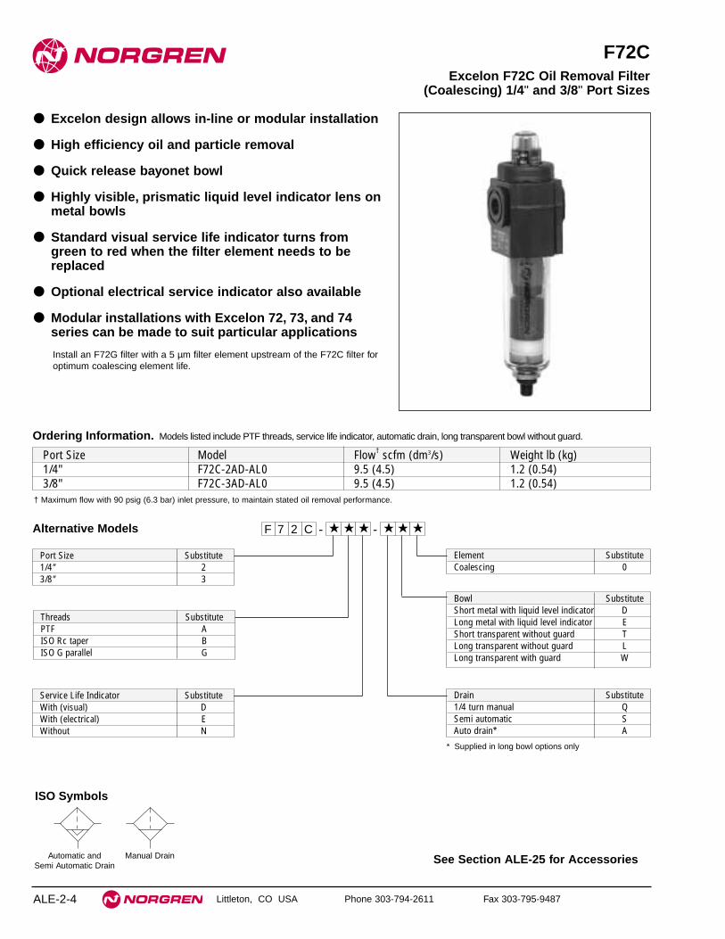
See Section ALE-25 for Accessories
Littleton, CO USA Phone 303-794-2611 Fax 303-795-9487
F72C
● Excelon design allows in-line or modular installation
● High efficiency oil and particle removal
● Quick release bayonet bowl
● Highly visible, prismatic liquid level indicator lens onmetal bowls
● Standard visual service life indicator turns fromgreen to red when the filter element needs to bereplaced
● Optional electrical service indicator also available
● Modular installations with Excelon 72, 73, and 74series can be made to suit particular applications
Install an F72G filter with a 5 µm filter element upstream of the F72C filter foroptimum coalescing element life.
Excelon F72C Oil Removal Filter(Coalescing) 1/4" and 3/8" Port Sizes
ALE-2-4
Ordering Information. Models listed include PTF threads, service life indicator, automatic drain, long transparent bowl without guard.
† Maximum flow with 90 psig (6.3 bar) inlet pressure, to maintain stated oil removal performance.
Port Size Model Flow† scfm (dm3/s) Weight lb (kg)1/4" F72C-2AD-AL0 9.5 (4.5) 1.2 (0.54)3/8" F72C-3AD-AL0 9.5 (4.5) 1.2 (0.54)
Element SubstituteCoalescing 0
Alternative Models
* Supplied in long bowl options only
F 7 2 -C ★ ★ - ★★ ★ ★
Port Size Substitute1/4" 23/8" 3
Threads SubstitutePTF AISO Rc taper BISO G parallel G
Drain Substitute1/4 turn manual QSemi automatic SAuto drain* A
Service Life Indicator SubstituteWith (visual) DWith (electrical) EWithout N
Bowl SubstituteShort metal with liquid level indicator DLong metal with liquid level indicator EShort transparent without guard TLong transparent without guard LLong transparent with guard W
Automatic and Semi Automatic Drain
Manual Drain
ISO Symbols

F72C Oil Removal (Coalescing) Filters
Littleton, CO USA Phone 303-794-2611 Fax 303-795-9487 ALE-2-5
PORT SIZE: 1/4"SATURATED ELEMENT
INLET PRESSURE: psig (bar)
FLOW CHARACTERISTICS
0 1 2 3 4 5 dm3/s
AIR FLOW
0 2 4 6 8 10 scfm
0.4
0.3
0.2
0.1
0
PR
ES
SU
RE
DR
OP
bar
d
5
4
3
2
1
0
psi
d
36(2.5)
23(1.6)
58(4.0)
91(6.3) 116
(8.0)
Maximum flow to maintain stated oil removal performance
1.97 (50)
1.89
(48
)
Short Bowl with 1/4 Turn Manual Drain
5.27
(13
4)
7.27
(18
5) †
2.10
(53
)
0.75
(19)Service Life
Indicator
Short Bowl with Semi auto Drain
6.93
(17
6)
8.94
(22
7) †
Long Bowl with Automatic Drain
5.51
(14
0)
7.52
(19
1) †
Long Bowl with Semi auto Drain
7.48
(19
0)
9.84
(25
0) †
Long Bowl with 1/4 Turn Manual Drain
5.83
(14
8)
7.83
(19
9) †
(Top)
† Minimum clearance required to remove bowl.
Service KitsItem Type Part NumberService kit Seal and gasket 4380-500Element Coalescing 5925-09Liquid level lens kit Prismatic 4380-030
1/4 turn manual 619-50Replacement drains Semi automatic 5379-RK
Automatic 4000-50RService kit includes bowl o-rings.
Technical DataFluid: Compressed airMaximum pressure:
Transparent bowl: Manual or semi automatic drain: 150 psig (10 bar)Automatic drain: 116 psig (8 bar)
Metal bowl: Manual or semi automatic drain: 250 psig (17 bar)Automatic drain: 116 psig (8 bar)
Operating temperature*: Transparent bowl: -30° to 125°F (-34° to 50°C)Metal bowl: -30° to 150°F (-34° to 65°C)
* Air supply must be dry enough to avoid ice formation at temperatures below 35°F (2°C).Particle removal: 0.01 µmAir quality: Within ISO 8573-1, Class 1 (particulates) and Class 2 (oil content)Maximum remaining oil content in outlet air:
0.01 ppm at 70°F (21°C) with an inlet concentration of 17 ppm.Maximum flow with 90 psig (6.3 bar) inlet pressure**: 9.5 scfm (4.5 dm3/s)** Maximum flow to maintain stated oil removal performance.Manual drain connection: Will fit 1/8-27 and 1/8-28 pipe thread.Semi automatic drain connection: Push on 5/16" (8 mm) ID tubeSemi automatic drain operating conditions (pressure operated):
Bowl pressure required to close drain: Greater than 1.5 psig (0.1 bar)Bowl pressure required to open drain: Less than 1.5 psig (0.1 bar) Minimum air flow required to close drain: 1 scfm (0.5 dm3/s)Manual operation: Lift stem to drain bowl
Automatic drain connection: Will fit 1/8-27 and 1/8-28 pipe thread. - Flexible tubewith 3/16" (5mm) minimum I.D. can be connected to the automatic drain. Drainmay fail to operate if the tube I.D. is less than 3/16" (5mm). Avoid restrictions inthe tube.
Automatic drain operating conditions (float operated):Bowl pressure required to close drain: Greater than 5 psig (0.3 bar) Bowl pressure required to open drain: Less than 3 psig (0.2 bar)Minimum air flow required to close drain: 0.2 scfm (0.1 dm3/s)Manual operation: Depress pin inside drain outlet to drain bowl
Nominal bowl sizeShort bowl: 1.9 fluid ounce (56 ml)Long bowl: 2.2 fluid ounce (65 ml)
MaterialsBody: ZincBowl
Transparent: PolycarbonateGuard for transparent bowl: ZincMetal: Zinc
Metal bowl liquid level indicator lens: Transparent nylonElement: Synthetic fiber and polyurethane foamElastomers: Neoprene and nitrileService life indicator
Body: transparent nylon.Internal parts: acetal.Spring: stainless steel.Elastomers nitrile
PORT SIZE: 1/4"DRY ELEMENT
INLET PRESSURE: psig (bar)
FLOW CHARACTERISTICS
0 4 8 12 16 20 dm3/s
0 8 16 24 32 40 scfm
0.4
0.3
0.2
0.1
0
PR
ES
SU
RE
DR
OP
bar
d
5
4
3
2
1
0
psi
d
36(2.5)
23(1.6)
58(4.0)
91(6.3)
116(8.0)
Typical Performance Characteristics
All Dimensions in Inches (mm)

See Section ALE-25 for Accessories
Littleton, CO USA Phone 303-794-2611 Fax 303-795-9487
F73C
● Excelon design allows in-line or modular installation
● Quick release bayonet bowl
● Highly visible, prismatic liquid level indicator lens
● Standard mechanical service indicator turns fromgreen to red when the filter element needs to bereplaced
● Optional electrical service indicator provideselectrical output when the filter element needs to be replaced
● Modular installations with Excelon 72, 73, and 74series can be made to suit particular applications
Excelon 73C Oil Removal Filter (Coalescing) 1/4", 3/8", and 1/2" Port Sizes
ALE-2-6
Install an F73G pre-filter with a 5 µm filter element upstream of the F73C filterfor optimum coalescing element life.
Ordering Information. Models listed include PTF threads, service indicator, automatic drain, and a metal bowl with liquid level indicator.
† Maximum flow with 90 psig (6.3 bar) inlet pressure to maintain stated oil removal performance.
Port Size Model Flow† scfm (dm3/s) Weight lb (kg)1/4" F73C-2AD-AD0 21.2 (10.0) 1.2 (0.54)3/8" F73C-3AD-AD0 21.2 (10.0) 1.2 (0.54)1/2" F73C-4AD-AD0 21.2 (10.0) 1.2 (0.54)
Alternative Models F 7 3 -C ★ ★ - ★★ ★ ★
Threads SubstitutePTF AISO Rc taper BISO G parallel G
Drain SubstituteAutomatic AManual, 1⁄4 turn Q
Bowl SubstituteMetal with liquid level indicator DTransparent with guard PTransparent T
Port Size Substitute1/4" 23/8" 31/2" 4
Element SubstituteCoalescing 0
Service Indicator SubstituteWith electrical service indicator EWith mechanical service indicator DWithout N
Automatic and Semi Automatic Drain
Manual Drain
ISO Symbols

F73C Oil Removal (Coalescing) Filters
Littleton, CO USA Phone 303-794-2611 Fax 303-795-9487 ALE-2-7
All Dimensions in Inches (mm)
Technical DataFluid: Compressed airMaximum pressure
Transparent bowl: 150 psig (10 bar)Metal bowl: 250 psig (17 bar)
Operating temperature*Transparent bowl: -30° to 125°F (-34° to 50°C)Metal bowl: -30° to 150°F (-34° to 65°C)
* Air supply must be dry enough to avoid ice formation at temperatures below 35°F (2°C).Particle removal: Down to 0.01 µmAir quality: Within ISO 8573-1, Class 1 (particulates) and Class 2 (oil content)Maximum remaining oil content in outlet air: 0.01 ppm at 70°F (20°C) with an inlet
concentration of 17 ppmMaximum flow at 90 psig (6.3 bar) inlet pressure to maintain stated oil removal
performance: 21.2 scfm (10 dm3/s)Manual drain connection: Will fit 1/8-27 and 1/8-28 pipe thread.Automatic drain connection: Will fit 1/8-27 and 1/8-28 pipe thread. - Flexible tube
with 3/16" (5mm) minimum I.D. can be connected to the automatic drain. Drainmay fail to operate if the tube I.D. is less than 3/16" (5mm). Avoid restrictions inthe tube.
Automatic drain operating conditions (float operated)Bowl pressure required to close drain: Greater than 5 psig (0.3 bar)Bowl pressure required to open drain: Less than 3 psig (0.2 bar)Minimum air flow required to close drain: 0.2 scfm (0.1 dm3/s) Manual operation: Depress pin inside drain outlet to drain bowl
Nominal bowl size: 3.5 fluid ounce (0.1 liter)Filter materials
Body: AluminumBowl
Transparent: PolycarbonateTransparent with guard: Polycarbonate, steel guardMetal: AluminumMetal bowl liquid level indicator lens: Transparent nylon
Element: Synthetic fiber and polyurethane foamElastomers: Neoprene and nitrile
Mechanical service indicator materialsBody: Transparent nylonInternal parts: AcetalSpring: Stainless steelElastomers: Nitrile
Typical Performance Characteristics
0 2 4 6 8 10 dm3/sAIR FLOW
0 4 8 12 16 20 scfm
PR
ES
SU
RE
DR
OP
0.4
0.3
0.2
0.1
0
bar
d
5
4
3
2
1
0
psi
d
PORT SIZE: 3/8"ELEMENT: SATURATED
FLOW CHARACTERISTICS
INLET PRESSURE:psig (bar) 15
(1.0)
36(2.5)
116(8.0)
90(6.3)
Maximum flow to maintain stated oil removal performance
0 4 8 12 16 20 dm3/s
0 8 16 24 32 40 scfm
PR
ES
SU
RE
DR
OP
0.4
0.3
0.2
0.1
0
bar
d
5
4
3
2
1
0 p
sid FLOW CHARACTERISTICS
15(1.0)
36(2.5)
90(6.3)
116(8.0)
PORT SIZE: 3/8"ELEMENT: DRYINLETPRESSURE:psig (bar)
1.00
(25
)
2.36
(60
)
Automatic Drain
MechanicalServiceIndicator
5.80
(14
7)
8.15
(20
7) *
*
2.68 (68)
2.45
(62
)1.22
(31
)
6.15
(15
6)
1/4 Turn Manual Drain
8.50
(21
6) *
*
Service kit includes element o-ring, automatic drain seal and bowl o-ring.
Service KitsItem Type Part NumberService kit Seal & Gasket 4380-602Replacement elements Coalescing 4444-01Liquid level lens kit Prismatic 4380-020
Replacement drainsAutomatic 4000-51RManual quarter turn 619-50
** Minimum clearance required to remove bowl.

See Section ALE-25 for Accessories
Littleton, CO USA Phone 303-794-2611 Fax 303-795-9487
F74C/H
● Excelon design allows in-line or modular installation
● Quick release bayonet bowl
● Highly visible, prismatic liquid level indicator lens
● Standard visual service indicator turns from green tored when the filter element needs to be replaced
● Optional electrical service indicator provideselectrical output when the filter element needs to be replaced
● Modular installations with Excelon 72, 73, and 74series can be made to suit particular applications
Excelon 74 Oil Removal Filters (Coalescing) 3/8", 1/2", and 3/4" Port Sizes
ALE-2-8
Install an F74G pre-filter with a 5 µm filter element upstream of the F74Cand F74H filters for optimum coalescing element life.
Ordering Information. Models listed include PTF threads, service indicator, automatic drain, and a metal bowl with liquid level indicator.
* Maximum flow with 90 psig (6.3 bar) inlet pressure to maintain stated oil removal performance.
Main Port Size Body and Element Model Number Maximum Flow* Weight scfm ( dm3/s) lb (kg)
3/8" Standard F74C-3AD-AD0 33.9 (16.0) 1.88 (0.85)1/2" Standard F74C-4AD-AD0 33.9 (16.0) 1.84 (0.83)1/2" High Flow F74H-4AD-AD0 59.3 (28.0) 2.45 (1.11)3/4" High Flow F74H-6AD-AD0 59.3 (28.0) 2.40 (1.10)
Alternative Models F 7 4 -★ ★ ★ - ★★ ★ ★
Threads SubstitutePTF AISO Rc taper BISO G parallel G
Service Life Indicator SubstituteWith (visual) DWith (electrical) EWithout N
Drain SubstituteAutomatic AManual 1⁄4 turn Q
Element SubstituteCoalescing 0
Bowl SubstituteMetal with liquid level indicator DTransparent with guard PPort Size Substitute
3/8" 31/2" 43/4" 6
Body and Element SubstituteStandard* CHigh Flow** H
* available with 3/8" or 1/2" ports** available with 1/2" or 3/4" ports
Service KitsItem Type Part NumberService kit Seal and gasket 4380-730
Replacement elementsStandard 4344-01High flow 4344-02
Liquid level kit Prismatic 4380-050
Replacement drainsAutomatic (1/8 NPT outlet) 3000-10Manual quarter turn 619-50
Service kits include element seal, bowl seal and drain seal.

F74C/H Oil Removal (Coalescing) Filters
Littleton, CO USA Phone 303-794-2611 Fax 303-795-9487 ALE-2-9
All Dimensions in Inches (mm)
Technical DataFluid: Compressed airMaximum pressure
Transparent bowl: 150 psig (10 bar)Metal bowl: 250 psig (17 bar)
Operating temperature*Transparent bowl: -30° to 125°F (-34° to 50°C)Metal bowl: -30° to 150°F (-34° to 65°C)
* Air supply must be dry enough to avoid ice formation at temperatures below 35°F (2°C).Particle removal: Down to 0.01 µmAir quality: Within ISO 8573-1, Class 1 (particulates) and Class 2 (oil content)Maximum remaining oil content in outlet air: 0.01 ppm at 70°F (20°C) with an inlet
concentration of 17 ppmMaximum flow at 90 psig (6.3 bar) inlet pressure to maintain stated oil removal
performanceF74C: 33.9 scfm (16 dm3/s)F74H: 59.3 scfm (28 dm3/s)
Manual drain connection: Will fit 1/8-27 and 1/8-28 pipe thread.Automatic drain connection: Will fit 1/8-27 and 1/8-28 pipe thread. - Flexible tube
with 3/16" (5mm) minimum I.D. can be connected to the automatic drain. Drainmay fail to operate if the tube I.D. is less than 3/16" (5mm). Avoid restrictions inthe tube.
Automatic drain operating conditions (float operated)Bowl pressure required to close drain: Greater than 5 psig (0.3 bar)Bowl pressure required to open drain: Less than 3 psig (0.2 bar)Minimum air flow required to close drain: 2 scfm (1 dm3/s) Manual operation: Depress pin inside drain outlet to drain bowl
Nominal bowl size: 7 fluid ounce (0.2 liter)Materials
Body: AluminumBowl
Transparent: Polycarbonate with steel bowl guardMetal: Aluminum
Metal bowl liquid level indicator lens: Transparent nylonElement: Synthetic fiber and polyurethane foamElastomers: Neoprene and NitrileService indicator
Body: Transparent nylon
Typical Performance Characteristics
0 5 10 15 20 25 dm3/s
AIR FLOW
0 10 20 30 40 50 scfm
0.6
0.4
0.2
0
PR
ES
SU
RE
DR
OP
bar
d
10
8
6
4
2
0
psi
d
PORT SIZE: 1/2"ELEMENT: SATURATED (F74C)
36(2.5)
90(6.3)
58(4.0)
150(10.0)
116(8.0)
INLET PRESSURE: psig (bar g)
FLOW CHARACTERISTICS
Maximum flow to maintain stated oil removal performance
PR
ES
SU
RE
DR
OP 0.6
0.4
0.2
0
bar
d
10
8
6
4
2
0 p
sid
PORT SIZE: 1/2"ELEMENT: DRY (F74C)
36(2.5)
58(4.0)
150(10.0)
90(6.3)
116(8.0)
INLET PRESSURE: psig (bar g)
AIR FLOW
0 10 20 30 40 50 dm3/s
0 20 40 60 80 100 scfm
FLOW CHARACTERISTICSF74C
PR
ES
SU
RE
DR
OP 0.6
0.4
0.2
0
bar
d
10
8
6
4
2
0
psi
d PORT SIZE: 1/2"ELEMENT: SATURATED (F74H)
36(2.5)
58(4.0)
90(6.3)
116(8.0)
INLET PRESSURE: psig (bar g)
AIR FLOW
0 10 20 30 40 50 dm3/s
0 20 40 60 80 100 scfm
FLOW CHARACTERISTICS
Maximum flow to maintain stated oil removal performance
PR
ES
SU
RE
DR
OP 0.6
0.4
0.2
0
bar
d
10
8
6
4
2
0
psi
d
PORT SIZE: 1/2"ELEMENT: DRY (F74H)
36(2.5)
58(4.0)
150(10.0)
90(6.3)
116(8.0)
INLET PRESSURE: psig (bar g)
0 20 40 60 80 100 dm3/s
AIR FLOW
0 40 80 120 160 200 scfm
FLOW CHARACTERISTICS
8.44
(21
5)
F74H, Automatic Drain
9.04
(23
0)
11.1
8 (2
84)
**
11.8
1 (3
00)*
*
F74H, 1/4 Turn Manual Drain
6.95
(17
7)
F74C, 1/4 Turn Manual Drain
9.80
(24
9) *
*
3.15 (80)
1.45
(37
)
2.89
(74
)2.
36 (
60)†
1.00
(25
)
ServiceIndicator
6.35
(16
1)
F74C, Automatic Drain
9.17
(23
3) *
*
** Minimum clearance required to remove bowl.† Dimension for alternative electrical service indicator is 1.98" (50.4 mm)
Automatic and Semi Automatic Drain
Manual Drain
ISO Symbols

See Section ALE-25 for Accessories
Littleton, CO USA Phone 303-794-2611 Fax 303-795-9487
F64C/H
● Olympian Plus plug in design
● High efficiency oil and particle removal
● Quick release bayonet bowl
● High visibility prismatic sight glass
● Coalescing element service indicator
Install an F64G pre-filter with a 5 µm filter element upstream of the F64C filter
for optimum coalescing element life.
Olympian Plus Puraire High Efficiency Oil Removal Filter 1/4", 3/8", 1/2", and 3/4" Port Sizes
ALE-2-10
Ordering Information. Models listed include PTF threads, service indicator, automatic drain, and metal bowl.
For replacement Filter (without yoke or pre-filter) substitute ‘N’ at the 5th and 6th digits eg: F64H-NND-AD0.
* Maximum flow with 90 psig (6.3 bar) inlet pressure to maintain stated oil removal performance.
Drain Type Port Size F64C/H (only) Maximum Flow* With 5µm F64G Pre-filterModel scfm ( dm3/s) Weight lb (kg) Model Weight lb (kg)
1⁄4" F64C-2AD-AD0 34 (16) 3.26 (1.48) FFC64-208 5.45 (2.47)
Automatic 3⁄8" F64H-3AD-AD0 60 (28) 3.75 (1.70) FFC64-308 5.93 (2.69)1⁄2" F64H-4AD-AD0 60 (28) 3.68 (1.67) FFC64-408 5.86 (2.66)3⁄4" F64H-6AD-AD0 60 (28) 4.43 (2.01) FFC64-608 6.66 (3.02)
F 6 4 -★ ★ ★ - ★★ ★ ★
Port Size Substitute1/4" 23/8" 31/2" 43/4" 6
Threads SubstitutePTF AISO Rc taper BISO G parallel G
Drain SubstituteManual, 1/4 turn QAuto drain A
Element SubstituteCoalescing 0
Body type SubstituteFor 1/4 CFor 3/8, 1/2, 3/4 H
Service Life Indicator SubstituteWith (visual) DWithout NWith (electrical)† E
Alternative Models
Bowl SubstituteMetal with liquid level indicator DTransparent with guard P
Automatic and Semi Automatic Drain
Manual Drain
ISO Symbols

F64C/H Oil Removal (Coalescing) Filters
Littleton, CO USA Phone 303-794-2611 Fax 303-795-9487 ALE-2-11
Typical Performance CharacteristicsInlet Pressure Maximum Flow†
F64C F64Hpsig (bar) scfm (dm
3/s) scfm (dm
3/s)
15 (1) 14 (6.4) 24 (11.2)45 (3) 23 (11.0) 41 (19.3)70 (5) 30 (14.3) 53 (24.9)90 (6.3) 34 (16.0) 59 (28.0)100 (7) 36 (16.9) 63 (29.5)130 (9) 40 (19.1) 71 (33.5)
† Maximum flow to maintain stated oil removal performance.
Service KitsItem Type Part NumberService kit F64C/H 4380-200Service kit (pre-filter) F64G 4380-200Element F64G (pre-filter) 5 µm 4338-01Element F64C Coalescing 4344-01Element F64H Coalescing 4344-02
Replacement sight glassPrismatic (standard) 4380-040Pyrex 4380-041
Replacement drainsAutomatic 3000-97Manual 684-84
Service kit includes port seals, louver o-ring, bowl o-ring and drain gasket.
4.13 (105)†1.
46(3
7)
2.91
(74)
F64C, Automatic Drain
9.40
(23
9)††
1.46
(37)
6.45
(16
4)2.
32 (
59)
7.05
(17
9)
F64C, 1/4 Turn Manual Drain
10.0
0 (2
54)†
†
† 6.18" (157) for 3/4" ports.†† Minimum clearance required to remove unit.
11.5
7 (2
94)†
†
8.58
(21
8)
F64H, Automatic Drain F64H, 1/4 Turn Manual Drain
12.2
0 (3
10)†
†
9.21
(23
4)
ServiceIndicator
All Dimensions in Inches (mm)
Technical DataFluid: Compressed airMaximum pressure:
Guarded transparent bowl: 150 psig (10 bar)Metal bowl: 250 psig (17 bar)
Operating temperature*:Guarded transparent bowl: -30° to 125°F (-34° to 50°C)Metal bowl: -30° to 150°F (-34° to 65°C)
* Air supply must be dry enough to avoid ice formation at temperatures below 35°F ( 2°C).Particle removal: 0.01 µm.Air quality: Within ISO 8573-1, Class 1 (particulates) and Class 2 (oil content)Maximum remaining oil content in outlet air:
0.01 ppm at 70°C (21°C) with an inlet concentration of 17 ppmMaximum flow at 90 psig (6.3 bar) inlet pressure**:
34 scfm (16dm3/s) F64C, 60 scfm (28 dm3/s) F64H ** To maintain stated oil removal performanceAutomatic drain connection: Will fit 1/8-27 and 1/8-28 pipe thread. - Flexible tube
with 3/16" (5mm) minimum I.D. can be connected to the automatic drain. Drainmay fail to operate if the tube I.D. is less than 3/16" (5mm). Avoid restrictions inthe tube.
Automatic drain operating conditions (float operated)Bowl pressure required to close drain: Greater than 5 psig (0.3 bar)Bowl pressure required to open drain: Less than 3 psig (0.2 bar)Minimum air flow required to close drain: 2 scfm (1 dm3/s) Manual operation: Depress pin inside drain outlet to drain bowl
Nominal bowl size:7 fluid ounce (0.2 liter)
Materials:Body: ZincYoke: ZincMetal bowl: AluminumStandard metal bowl prismatic liquid level indicator lens: GrilamidOptional metal bowl sight glass: PyrexOptional transparent bowl: PolycarbonateElement: Composite materialsElastomers: Synthetic rubberService life indicator:
Body: Transparent nylon.Internal parts: Acetal.Spring: Stainless steel.Elastomers: Nitrile.
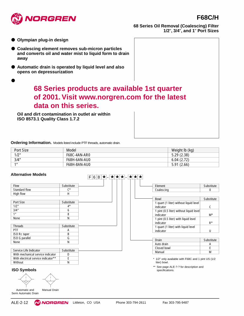
Littleton, CO USA Phone 303-794-2611 Fax 303-795-9487
F68C/H
● Olympian plug-in design
● Coalescing element removes sub-micron particlesand converts oil and water mist to liquid form to drainaway
● Automatic drain is operated by liquid level and alsoopens on depressurization
●
Oil and dirt contamination in outlet air withinISO 8573.1 Quality Class 1.7.2
68 Series Oil Removal (Coalescing) Filter1/2", 3/4", and 1" Port Sizes
ALE-2-12
Port Size Model Weight lb (kg)1/2" F68C-4AN-AR0 5.29 (2.38)3/4" F68H-6AN-AU0 6.04 (2.72)1" F68H-8AN-AU0 5.91 (2.66)
Drain SubstituteAuto drain AClosed bowl EManual M
Element SubstituteCoalescing 0
Service Life Indicator SubstituteWith mechanical service indicator DWith electrical service indicator** EWithout N
Flow SubstituteStandard flow C*High flow H
Alternative Models
* 1/2" only available with F68C and 1 pint US (1/2liter) bowl.
** See page ALE-?-? for description andspecifications.
Ordering Information. Models listed include PTF threads, automatic drain.
Threads SubstitutePTF AISO Rc taper BISO G parallel GNone N
Port Size Substitute1/2" 4*3/4" 61" 8None N
Bowl Substitute1 quart (1 liter) without liquid level indicator C1 pint (0.5 liter) without liquid level indicator M*1 pint (0.5 liter) with liquid level indicator R*1 quart (1 liter) with liquid level indicator U
F 6 8 -★ ★ ★ - ★★ ★ ★
Automatic and Semi Automatic Drain
Manual Drain
ISO Symbols
68 Series products are available 1st quarter of 2001. Visit www.norgren.com for the latestdata on this series.

F68C, F68GH Oil Removal (Coalescing) Filters
Littleton, CO USA Phone 303-794-2611 Fax 303-795-9487 ALE-2-13
Technical DataFluid: Compressed airMaximum pressure
Metal bowl: 250 psig (17 bar)Operating temperature*
Metal bowl: 0° to 150°F (-20° to 65°C)* Air supply must be dry enough to avoid ice formation at temperatures below 35°F (2°C).Particle removal: 0.01 µmAir quality: Within ISO 8573-1, Class 1 (particulates) and
Class 2 (oil content).Maximum remaining oil content: 0.01mg/m3 at 70°F (21°C) with an inlet
concentration of 17 mg/m3.Maximum flow at 90 psig (6.3 bar) inlet pressure**
G1/2, CDS15 element: 74 scfm (35 dm3/s)TBA from Lab Test
G3/4, CDS25 element: 74 scfm (35 dm3/s)TBA from Lab Test
G1, CDS25 element: 127 scfm (60 dm3/s)TBA from Lab Test** To maintain stated oil removal performanceAutomatic drain connection: Will fit 1/8-27 and 1/8-28 pipe thread. - Flexible
tube with 3/16" (5mm) minimum I.D. can be connected to the automatic drain.Drain may fail to operate if the tube I.D. is less than 3/16" (5mm). Avoidrestrictions in the tube.
Automatic drain operating conditionsMinimum pressure: 10 psig (0.7 bar).Drain opens when bowl pressure drops below 3 psig (0.2 bar).Minimum air flow: 2 scfm (1 dm3/s) required to close drain.
Nominal bowl sizes:1 quart (1 liter)
† For mechanical service indicator add 1.38" (35 mm). For electrical service indicator add 1.98" (50.4 mm).For closed bowl subtract 0.35" (9 mm) from auto drain dimension.
†† Minimum clearance required to remove bowl.
0.5 liter, automatic drain 0.5 liter, manual drain 1 litre, automatic drain1 litre, manual drain
8.94
(22
7)†
8.43
(21
4)†
††
G1/8
1.73
(44
)
1.38
(35
)
9.21
(23
4)†
8.70
(22
1)†
††
1.73
(44
)
1.38
(35
)
12.2
8 (3
12)†
11.7
7 (2
99)†
††
G1/8
1.73
(44
)
1.38
(35
)
2.13
(54
)
4.92 (125)
12.5
6 (3
19)†
12.0
5 (3
06)†
††
1.73
(44
)
1.38
(35
)
Service Kits
Item Type Part NumberService Kit 4380-301Replacement CDS15 5351-98Elements CDS25 5351-99Replacement 1 pint (0.5 liter) 4380-060Sight Glass 1 quart (1 liter) 4380-062Replacement Automatic 3000-04Drains Manual 684-84Service Life Mechanical 5797-50Indicators Electrical 4020-51R
Service kit Includes: ……TBA.
Typical Performance Characteristics
Inlet Pressure Maximum Flow*G1/2 G3/4 G1
CDS15 CDS25 CDS25psig (bar) scfm (dm3/s) scfm (dm3/s) scfm (dm3/s)
15(1) 30(14)30(14)51(24)
45*
All Dimensions in Inches (mm)
68 Series products are available 1st quarter of 2001. Visit www.norgren.com for the latestdata on this series.

See Section ALE-25 for Accessories
Littleton, CO USA Phone 303-794-2611 Fax 303-795-9487
F46
● High efficiency oil and particle removal
● Screw-on bowl reduces maintenance time
● Can be disassembled without the use of tools orremoval from the air line
● Standard service indicator turns from green to redwhen the filter element needs to be replaced
NOTE: Install an F17 filter with a 5 µm filter element upstream of theF46 filter for maximum service life.
F46 Oil Removal (Coalescing) Filter 3/4", 1", and 1-1/4" Port Sizes
ALE-2-14
Ordering Information. Models listed include service indicator, automatic drain, metal bowl with sight glass, and PTF threads.
Port Size Model Numbers Maximum Flow* scfm (dm3/s) Weight lbs (kg)3/4" F46-601-A0DA 90 (42) 4.11 (1.86)1" F46-801-A0DA 125 (59) 4.05 (1.84)1-1/4" F46-A01-A0DA 125 (59) 4.29 (1.95)
Alternative Models - ★★★ ★★ ★ -4 ★F 6
Threads SubstitutePTF AISO Rc taper BISO G parallel G
Drain SubstituteAutomatic AManual M
Bowl SubstituteMetal with sight glass DMetal M
Port Size Substitute3/4" 61" 81-1/4" A
Element SubstituteCoalescing 0
Option SubstituteNot applicable 0
Service Life Indicator SubstituteWithout 0With (visual) 1With (electrical) 4
* Maximum flow for oil-saturated element at 90 psig (6.3 bar) inlet pressure to maintain stated oil removal performance.
Automatic and Semi Automatic Drain
Manual Drain
ISO Symbols

F46 Oil Removal (Coalescing) Filters
Littleton, CO USA Phone 303-794-2611 Fax 303-795-9487 ALE-2-15
All Dimensions in Inches (mm)
4.32
(11
0)
4.75 (121)
Service Indicator
1.25
(32)
2.61
(66)
10.0
6 (2
56)
AutomaticDrain
2.40(61)
16.7
1 (4
24)*
*
Service Indicator
1.25
(32)
2.61
(66)
ManualDrain
17.2
9 (4
39)*
*
10.6
3 (2
70)
2.40(61)
** Minimum clearance required to remove bowl.
Technical DataFluid: Compressed airMaximum pressure: 250 psig (17 bar )Operating temperature:* -30° to 150°F (-34° to 65°C )* Air supply must be dry enough to avoid ice formation at temperatures below 35°F (2°C) Particle removal: Down to 0.01 µmAir quality: Within ISO 8573-1, Class 1 (particulates) and Class 2 (oil content)Maximum remaining oil content in outlet air: 0.01ppm at 70°F (20°C) with an inlet
oil concentration of 17 ppm.Maximum flow at 90 psig (6.3 bar) inlet pressure to maintain stated oil removalperformance:
3/4" ports: 90 scfm (42 dm3/s)1" ports: 125 scfm (59 dm3/s)1-1/4" ports: 125 scfm (59 dm3/s)
Nominal bowl size: 1 quart US (1 liter)Manual drain connection: Will fit 1/8-27 and 1/8-28 pipe thread.Automatic drain connection: Will fit 1/8-27 and 1/8-28 pipe thread. - Flexible tube
with 3/16" (5mm) minimum I.D. can be connected to the automatic drain. Drainmay fail to operate if the tube I.D. is less than 3/16" (5mm). Avoid restrictions inthe tube.
Automatic drain operating conditions (float operated)Bowl pressure required to close drain: Greater than 5 psig (0.3 bar)Bowl pressure required to open drain: Less than 3 psig (0.2 bar)Minimum air flow required to close drain: 2 scfm (1 dm3/s) Manual operation: Depress pin inside drain outlet to drain bowl
MaterialsBody: AluminumBowl: AluminumBowl sight glass: PyrexElastomers: Neoprene and nitrileFilter element: Synthetic fiber and polyurethane foam
Typical Performance Characteristic
PR
ES
SU
RE
DR
OP 0.3
0.2
0.1
0 b
ar d
5
4
3
2
1
0
psi
d
PORT SIZE: 1"ELEMENT: COALESCING, OIL SATURATED
0 25 50 75 100 125 dm3/s
AIR FLOW
0 50 100 150 200 250 scfm
58 (4.0)36 (2.5)INLETPRESSURE:psig (bar g)
90 (6.3) 116 (8.0) 150 (10.0)
Maximum flow to maintain stated oil removal performance
PR
ES
SU
RE
DR
OP 0.3
0.2
0.1
0
bar
d
5
4
3
2
1
0
psi
d
0 50 100 150 200 250 dm3/s
AIR FLOW
0 100 200 300 400 500 scfm
150(10.0)
58 (4.0)36 (2.5)INLET PRESSURE:psig (bar g)
90 (6.3) 116 (8.0)
PORT SIZE: 1"ELEMENT: COALESCING, DRY
Service KitsItem Type Part numberService kit O-ring & gaskets 5351-04
Automatic (1/8 NPT outlet) 3000-18Replacement drains
Manual (1/4 Turn) 619-50
Service kit contains coalescing element, element o-ring, bowl o-ring, and drain gasket.

See Section ALE-25 for Accessories
Littleton, CO USA Phone 303-794-2611 Fax 303-795-9487
F47
● High efficiency oil and particle removal
● Highly visible, prismatic liquid level indicator lens
● Patented quarter turn manual drain
● Can be disassembled without removal from the airline
● Standard service indicator turns from green to redwhen the filter element needs to be replaced
● Optional electrical service indicator also available
18 Series Oil Removal Filter(Coalescing) 1-1/2" and 2" Port Sizes
ALE-2-16
Alternative Models - ★★★ ★★ ★ -4 ★F 7
Drain SubstituteAutomatic AManual, 1/4 turn M
Bowl SubstituteMetal with sight glass DMetal M
Port Size Substitute1-1/2" B2" C
Element SubstituteCoalescing 0
Option SubstituteStandard body and element 0High flow body and element (use only with 22" ports)
Service Indicator SubstituteWithout 0With (visual) 1With (electrical) 4
Ordering Information. Models listed include service indicator, automatic drain, metal bowl with sight glass, and PTF threads.
Port Size Body and Element Model Numbers Flow scfm (dm3/s)* Weight lbs (kg)1-1/2" Standard F47-B01-A0DA 250 (118) 15.51 (7.04)2" Standard F47-C01-A0DA 300 (142) 14.26 (6.47)2" High Flow F47-C21-A0DA 600 (283) 22.17 (10.06)
* Maximum flow at 90 psig (6.3 bar) inlet pressure to maintain stated oil removal performance.
Threads SubstitutePTF AISO Rc taper BISO G parallel G
Automatic and Semi Automatic Drain
Manual Drain
ISO Symbols
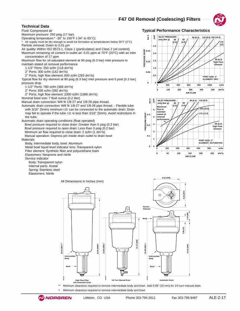
F47 Oil Removal (Coalescing) Filters
Littleton, CO USA Phone 303-794-2611 Fax 303-795-9487 ALE-2-17
Technical DataFluid: Compressed airMaximum pressure: 250 psig (17 bar)Operating temperature:* -30° to 150°F (-34° to 65°C)* Air supply must be dry enough to avoid ice formation at temperatures below 35°F (2°C).Particle removal: Down to 0.01 µmAir quality: Within ISO 8573-1, Class 1 (particulates) and Class 2 (oil content)Maximum remaining oil content in outlet air: 0.01 ppm at 70°F (20°C) with an inlet
concentration of 17 ppmMaximum flow for oil-saturated element at 90 psig (6.3 bar) inlet pressure tomaintain stated oil removal performance
1-1/2" Ports: 250 scfm (118 dm3/s)2" Ports: 300 scfm (142 dm3/s)2" Ports, high flow element: 600 scfm (283 dm3/s)
Typical flow for dry element at 90 psig (6.3 bar) inlet pressure and 5 psid (0.3 bar)pressure drop
1-1/2" Ports: 780 scfm (368 dm3/s)2" Ports: 830 scfm (392 dm3/s)2" Ports, high flow element: 2300 scfm (1086 dm3/s)
Nominal bowl size: 7 fluid ounce (0.2 liter)Manual drain connection: Will fit 1/8-27 and 1/8-28 pipe thread.Automatic drain connection: Will fit 1/8-27 and 1/8-28 pipe thread. - Flexible tube
with 3/16" (5mm) minimum I.D. can be connected to the automatic drain. Drainmay fail to operate if the tube I.D. is less than 3/16" (5mm). Avoid restrictions inthe tube.
Automatic drain operating conditions (float operated)Bowl pressure required to close drain: Greater than 5 psig (0.3 bar)Bowl pressure required to open drain: Less than 3 psig (0.2 bar)Minimum air flow required to close drain: 2 scfm (1 dm3/s) Manual operation: Depress pin inside drain outlet to drain bowl
MaterialsBody, intermediate body, bowl: AluminumMetal bowl liquid level indicator lens: Transparent nylonFilter element: Synthetic fiber and polyurethane foamElastomers: Neoprene and nitrile Service indicator
Body: Transparent nylonInternal parts: AcetalSpring: Stainless steelElastomers: Nitrile
0.3
0.2
0.1
0P
RE
SS
UR
E D
RO
P
5
4
3
2
1
0
psi
d
bar
d
PORT SIZE: 2"ELEMENT: SATURATED
0 50 100 150 200 250 dm3/s
AIR FLOW
0 100 200 300 400 500 scfm
36(2.5)
58(4.0)
INLET PRESSURE:psig (bar g)
116 (8.0)
150 (10.0)
90 (6.3)
High FlowElement
90 (6.3)
175 (12.0)
Maximum flow to maintain stated oil removal performance
PR
ES
SU
RE
DR
OP 0.15
0.10
0.05
0
bar
d
2.5
2.0
1.5
1.0
0.5
0
psi
d
PORT SIZE: 2"ELEMENT: DRY
0 100 200 300 400 500 dm3/s
AIR FLOW
0 200 400 600 800 1000 scfm
58(4.0)
INLET PRESSURE:psig (bar g)
116 (8.0) 150 (10.0)90 (6.3)
High FlowElement
90 (6.3)
36(2.5) 175
(12)
Typical Performance Characteristics
8.16
(20
7)
8.22 (209)
15.7
0 (3
99)
1/4 Turn Manual Drain
23.5
8 (5
99)
†
23.5
5 (5
98)*
*
High Flow Filterwith Automatic Drain
39.2
5 (9
97)
**
15.1
0 (3
84)
1.86
(47
)
3.16
(80
)
Automatic Drain
22.9
9 (5
84)
†
ServiceIndicator
IntermediateBody
Bowl
IntermediateBody
Bowl
Body
** Minimum clearance required to remove intermediate body and bowl. Add 0.59" (15 mm) for 1/4 turn manual drain.
† Minimum clearance required to remove intermediate body and bowl.
All Dimensions in Inches (mm)


Littleton, CO USA Phone 303-794-2611 Fax 303-795-9487 ALE-3-1
Section 3
Oil Vapor Removal(Adsorbing) Filtersavailable in port sizes 1/4" to 1".
F72V Excelon Oil Vapor Removal Filter 1/4" and 3/8" Ports . . . . . . . . . . . . . . . . . . . . . . . . .ALE-3-2
F74V Excelon Oil Vapor Removal Filter 3/8", 1/2", and 3/4" Ports . . . . . . . . . . . . . . . . . . . .ALE-3-4
F64B/L Coalescing/Oil Vapor Removal Filter 1/4", 3/8", 1/2", and 3/4" Ports . . . .ALE-3-6
F68V/Y Olympian Plus Oil Vapor Removal Filter 1/2", 3/4", and 1" Ports . . . . . . . . . . . . . . . . . . . . . .ALE-3-8
F46 Oil Vapor Removal Filter 3/8", 1/2", and 3/4" Ports . . . . . . . . . . . . . . . . . . .ALE-3-10
F72V F74V
F46F68
F64 B/L
Product available 1stquarter of 2001

See Section ALE-25 for Accessories
Littleton, CO USA Phone 303-794-2611 Fax 303-795-9487
F72V
● Excelon design allows in-line or modular installation
● Adsorbing type activated carbon element removes oilvapors and most hydrocarbon odors
● Quick release bayonet bowl
● Long service life of filter element.
● Color indicator for oil presence.
● Modular installations with EXCELON 72, 73, and 74series can be made to suit particular applications
Excelon 72 Oil Vapor Removal Filter 1/4", 3/8" Port Sizes
ALE-3-2
Ordering Information. Models listed include PTF threads and a long transparent bowl without guard and closed bottom.
* Maximum flow at 90 psig (6.3 bar) inlet pressure to maintain stated oil removal performance.
Port Size Model Flow* scfm (dm3/s) Weight lb (kg)1/4" F72V-2AN-ELC 3.4 (1.6) 0.88 (0.40)3/8" F72V-3AN-ELC 3.4 (1.6) 0.88 (0.40)
Alternative ModelsF 7 2 -V ★ ★ - ★N E C
Port Size Substitute1/4" 23/8" 3
Threads SubstitutePTF AISO Rc taper BISO G parallel G
Bowl SubstituteLong metal CShort metal MShort transparent without guard TLong transparent without guard LLong transparent with guard W
ISO Symbols
Auto Drain

F72V Oil Vapor Removal Filter
Littleton, CO USA Phone 303-794-2611 Fax 303-795-9487 ALE-3-3
Technical DataFluid: Compressed airMaximum pressure
Transparent bowl: 150 psig (10 bar)Metal bowl: 250 psig (17 bar)
Operating temperature* Transparent bowl: 0° to 125°F (-20° to 50°C)Metal bowl: 0° to 150°F (-20° to 65°C)
* Air supply must be dry enough to avoid ice formation at temperatures below 35°F (2°C).Required prefilter: Norgren oil removal filter with equivalent pipe size and flow
capacity equal to or greater than the vapor removal filter.Air quality: Within ISO 8573-1, Class 1** (oil content) when installed downstream of
an oil removal filter** See ALE-1-G for specification details.Maximum remaining oil content in outlet air: 0.003 ppm at 70°F (20°C)Maximum flow at 90 psig (6.3 bar) inlet pressure to maintain stated oil removal
performance: 3.4 scfm (1.6 dm3/s)Nominal bowl size
Short bowl: 1.9 fluid ounce (56 ml)Long bowl: 2.2 fluid ounce (65 ml)
MaterialsBody: ZincBowl
Transparent: PolycarbonateGuard for transparent bowl: ZincMetal: Zinc
Element: Activated carbon and polycarbonateElastomers: Nitrile
Typical Performance Characteristics
PORT SIZE: 3/8"
FLOW CHARACTERISTICS
0 1 2 3 4 5 dm3/s
AIR FLOW
0 2 4 6 8 10 scfm
0.4
0.3
0.2
0.1
0
PR
ES
SU
RE
DR
OP
bar
d
5
4
3
2
1
0
psi
d
36(2.5)
58(4.0)
91(6.3)
Maximum flow to maintain stated oil removal performance
116(8)INLET PRESSURE: psig (bar)
150(10)
1.97 (50)
1.89
(48
)
Short Bowl Long Bowl
4.49
(11
4)
6.89
(17
5) †
4.88
(12
4)
7.28
(18
5)
0.75
(19)
Service kit includes element seal and bowl seal.
Service KitsItem Type Part NumberService kit Seal and Gasket 4380-500Replacement element Adsorbing 4241-01
† Minimum clearance required to remove bowl.
All Dimensions in Inches (mm)

See Section ALE-25 for Accessories
Littleton, CO USA Phone 303-794-2611 Fax 303-795-9487
F74V
● Excelon design allows in-line or modular installation
● Adsorbing type activated carbon element removesoil vapors and most hydrocarbon odors
● Quick release bayonet bowl
● Long service life of filter element. Minimum life of400 hours when an oil removal filter is installedupstream and the filtration temperature is in theregion of 70° to 80°F (20° to 26°C).
● Modular installations with Excelon 72, 73, and 74series can be made to suit particular applications
Excelon 74 Oil Vapor Removal Filter 3/8", 1/2", 3/4" Port Sizes
ALE-3-4
Ordering Information. Models listed include PTF threads and a closed bottom metal bowl.
* Maximum flow with 90 psig (6.3 bar) inlet pressure to maintain stated oil vapor removal performance.
Port Size Model Flow* scfm (dm3/s) Weight lb (kg)3/8" F74V-3AN-EMA 27 (13) 2.54 (1.15)1/2" F74V-4AN-EMA 27 (13) 2.51 (1.14)3/4" F74V-6AN-EMA 27 (13) 2.46 (1.12)
Alternative ModelsF 7 4 -V ★ ★ - ★★ ★ ★
Threads SubstitutePTF AISO Rc taper BISO G parallel G
Options SubstituteNo options N
Drain SubstituteClosed bottom (no drain) E
Element SubstituteAdsorbing (Activated carbon Awithout color indicator)
Bowl SubstituteMetal MTransparent with guard P
Port Size Substitute3/8" 31/2" 43/4" 6
ISO Symbols
Auto Drain
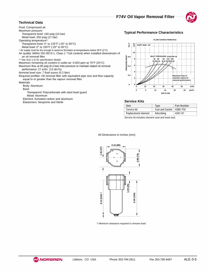
F74V Oil Vapor Removal Filter
Littleton, CO USA Phone 303-794-2611 Fax 303-795-9487 ALE-3-5
All Dimensions in Inches (mm)
Technical DataFluid: Compressed airMaximum pressure:
Transparent bowl: 150 psig (10 bar)Metal bowl: 250 psig (17 bar)
Operating temperature*:Transparent bowl: 0° to 125°F (-20° to 50°C)Metal bowl: 0° to 150°F (-20° to 65°C)
* Air supply must be dry enough to avoid ice formation at temperatures below 35°F (2°C)Air quality: Within ISO 8573-1, Class 1 **(oil content) when installed downstream of
an oil removal filter** See ALE-1-G for specification details.Maximum remaining oil content in outlet air: 0.003 ppm at 70°F (20°C)Maximum flow at 90 psig (6.3 bar) inlet pressure to maintain stated oil removal
performance: 27 scfm (13 dm3/s)Nominal bowl size: 7 fluid ounce (0.2 liter)Required prefilter: Oil removal filter with equivalent pipe size and flow capacity
equal to or greater than the vapour removal filter.Materials
Body: AluminumBowl:
Transparent: Polycarbonate with steel bowl guardMetal: Aluminum
Element: Activated carbon and aluminumElastomers: Neoprene and Nitrile
Typical Performance Characteristics
0 5 10 15 20 25 dm3/s
AIR FLOW
0 10 20 30 40 50 scfm
PR
ES
SU
RE
DR
OP 0.6
0.4
0.2
0
bar
d
10
8
6
4
2
0
psi
d
PORT SIZE: 1/2"
36(2.5)
90(6.3)
58(4.0)
150(10.0)
116(8.0)
INLET PRESSURE: psig (bar g)
FLOW CHARACTERISTICS
Maximum flow to maintain stated oil removal performance
2.89
(74
)
3.15 (80)
1.45
(37
)
6.30
(16
0)
1.00
(25
)
9.13
(23
2) †
Service kit includes element seal and bowl seal.
Service KitsItem Type Part NumberService kit Seal and Gasket 4380-750Replacement element Adsorbing 4341-01
† Minimum clearance required to remove bowl.

See Section ALE-25 for Accessories
Littleton, CO USA Phone 303-794-2611 Fax 303-795-9487
F64B/L
● Olympian Plus plug in design
● Combined oil and vapor removal filter
● Oil and dirt contamination in outlet air within ISO 8573-1: Quality class 1.7.1
For optimum coalescing filter element life install a 5 µm F64G pre-filter upstream.
Olympian Plus Coalescing/Adsorbing Filter 1/4", 3/8", 1/2", 3/4" Port Sizes
ALE-3-6
Ordering Information. Models listed include PTF threads, automatic drain and metal bowl.
For replacement Filter (without yoke or pre-filter) substitute ‘N’ at the 5th and 6th digits eg: F64L-NNN-AR0.
Drain Type Port Size F64B/L (only) With 5 µm F64G Pre-filterModel Weight lb (kg) Model Weight lb (kg)
1⁄4" F64B-2AN-AR0 4.07 (1.83) FFB64-208 7.11 (3.20)
Automatic 3⁄8" F64L-3AN-AR0 4.91 (2.21) FFB64-308 7.93 (3.57)1⁄2" F64L-4AN-AR0 5.56 (2.50) FFB64-408 8.00 (3.60)3⁄4 " F64L-6AN-AR0 6.40 (2.88) FFB64-608 8.84 (3.98)
F 6 4 -★ ★ ★ - ★★ ★ ★
Port Size Substitute1/4" 23/8" 31/2" 43/4" 6
Threads SubstitutePTF AISO Rc taper BISO G parallel G
Drain SubstituteManual MAuto drain A
Element SubstituteCoalescing 0
Body type SubstituteFor 1/4" ports BFor 3/8", 1/2", 3/4" ports L
Option SubstituteNone N
Alternative Models
Bowl SubstituteMetal with liquid level indicator DTransparent with guard P
ISO Symbols
Auto Drain Manual Drain

F64 B/L Coalescing/Vapor Removal Filters
Littleton, CO USA Phone 303-794-2611 Fax 303-795-9487 ALE-3-7
All Dimensions in Inches (mm)
Technical DataFluid: Compressed airMaximum pressure:
Guarded transparent bowl: 150 psig (10 bar)Metal bowl: 250 psig (17 bar)
Operating temperature*:Guarded transparent bowl: 0° to 125°F (-20° to 50°C)Metal bowl: 0° to 150°F (-20° to 65°C)
* Air supply must be dry enough to avoid ice formation at temperatures below 35°F (2°C).Partical removal: 0.01 µm.Air quality: Within ISO 8573-1, Class 1.7.1**** See ALE-1-G for specification details.Maximum remaining oil content in outlet air:
0.003 ppm at 70°C (21°C) with an inlet concentration of 17 ppmMaximum flow at 90 psig (6.3 bar) inlet pressure†:
15 scfm (7 dm3/s) F64B, 23 scfm (11 dm3/s) F64L Automatic drain connection: 1/8" pipe threadAutomatic drain operating conditions (float operated)
Bowl pressure required to close drain: Greater than 5 psig (0.3 bar)Bowl pressure required to open drain: Less than 3 psig (0.2 bar)Minimum air flow required to close drain: 2 scfm (1 dm3/s) Manual operation: Depress pin inside drain outlet to drain bowl
For F64G pre-filter technical data please refer to separate sheet.Materials
Body: ZincYoke: ZincMetal bowl: ZincOptional transparent bowl: PolycarbonateIntegral pre-filter element: Sintered bronzeMain filter element and activated carbon pack: Composite materialsElastomers: Synthetic rubberStandard sight glass for metal bowl: Pyrex
Typical Performance CharacteristicsInlet Pressure Maximum Flow†
F64B F64Lpsig (bar) scfm (dm3/s) scfm dm3/s15 (1) 6 (2.8) 9.3 (4.4)45 (3) 10 (4.8) 16 (7.6)70 (5) 13 (6.2) 20.8 (9.8)90 (6.3) 15 (7.0) 23.3 (11.0)100 (7) 15.5 (7.3) 24.4 (11.5)130 (9) 17.8 (8.4) 28 (13.2)
† Maximum flow to maintain stated oil removal performance.
* Automatic drain shown.Add 0.39" (10 mm) for manual drain
†† Minimum clearance required to remove bowl.** 6.18" (157 mm) for models with 3/4" ports
4.13 (105)**
1.46
(37
)
2.91
(74
)10
.63
(270
)*
11.2
6 (2
86)†
†
4.84
(12
3)
4.84
(12
3)
12.6
0 (3
20)*
13.2
3 (3
36)†
†
F64B (automatic drain)
F64L (automatic drain)
Service KitsItem Type Part NumberService kit F64B/L 4380-201Service kit (pre-filter) F64G 4380-200Element F64G (pre-filter) 5 µm 4338-01
Coalescing (F64B) 5350-99
Elements (F64B/L)Coalescing (F64L) 5350-98Integral pre-filter (F64B/L) 3698-02Activated carbon (F64B/L) 5568-01Prismatic (F64G) 4380-040
Replacement sight glass Pyrex (F64G option) 4380-041Pyrex (F64B/L) 2273-97
Replacement drainsAutomatic 3000-10Manual 684-84
Service kit includes port seals, bowl o-ring and drain gasket.

Littleton, CO USA Phone 303-794-2611 Fax 303-795-9487
F68V/Y
● Olympian plug in design
● Adsorbing type activated carbon element removesoil vapors and most hydrocarbon odours
Olympian Oil Vapor Removal Filter1/2", 3/4", 1" Port Sizes
ALE-3-8
Ordering Information. Models listed include PTF parallel threads and a closed bottom metal bowl.
* Maximum flow with 90 psig (6.3 bar) inlet pressure to maintain stated oil removal performance.
Port Size Model Flow* scfm (dm3/s) Weight lb (kg)1/2" F68V-4AN-EMA 53 (25) 2.54 (1.15)3/4" F68V-6AN-EMA 74 (35) 2.51 (1.14)1" F68V-8AN-EMA 127 (60) 2.46 (1.12)
Alternative ModelsF 6 8 -★ ★ ★ - MN E A
Flow SubstituteStandard flow V*High flow Y
Port Size Substitute1/2" 4*3/4" 61" 8None N
Bowls Substitute1 pint (1/2 liter) M*1 quart (1 liter) C
Threads SubstitutePTF AISO Rc taper BISO G parallel GNone N
* 1/2" only available with F68V and 1/2 liter(1 pint US) bowl.
ISO Symbols
Closed Bottom
68 Series products are available 1st quarter of 2001. Visit www.norgren.com for the latestdata on this series.

F68V/Y Vapor Removal Filters
Littleton, CO USA Phone 303-794-2611 Fax 303-795-9487 ALE-3-9
All Dimensions in Inches (mm)
Typical Performance Characteristics
Inlet Pressure Maximum Flow†psig (bar) scfm (dm3/s)36 (2.5) 19 (8.7)58 (4) 23 (10.7)90 (6.3) 28 (13.3)116 (8) 33 (15.6)150 (10) 38 (17.6)
† Maximum flow to maintain stated oil removal performance.
0 5 10 15 20 25 dm3/s
AIR FLOW
0 10 20 30 40 50 scfm
PR
ES
SU
RE
DR
OP 0.6
0.4
0.2
0
bar
d
10
8
6
4
2
0
psi
d
PORT SIZE: 1/2"
36(2.5)
90(6.3)
58(4.0)
150(10.0)
116(8.0)
INLET PRESSURE: psig (bar g)
FLOW CHARACTERISTICS
Maximum flow to maintain stated oil removal performance
†† Minimum clearance required to remove bowl.
Unported units.
For ported unit dimensions see Bracket Mounting dimensions below.
7.21
(18
3)
8.07
(20
5)††
1.73
(44
)
2.13
(54
)
4.92 (125)
10.5
5 (2
68)
11.4
2 (2
90)†
†
1.73
(44
)
F15V (short bowl) F15V (long bowl)
Technical DataFluid: Compressed airMaximum pressure: 250 psig (17 bar)Temperature range*: 0° to 150°F (-20° to 65°C)* Air supply must be dry enough to avoid ice formation at temperatures below 35°F (2°C).Air quality: Within ISO 8573-1, Class 1** (oil content) when installed downstream of
an oil removal filter** See ALE-?-? for specification details.
Maximum remaining oil content in outlet air: 0.003 mg/m3 at 70°F (20°C)Required pre-filter: Oil removal filter with equivalent pipe size and flow capacity
equal to or greater than the vapour removal filter.Approximate flow at 90 psig (6.3 bar) inlet pressure†:
1/2, CDS15 element: 53 scfm (25 dm3/s)
3/4, CDS25 element: 74 scfm (35 dm3/s)
1, CDS25 element: 127 scfm (60 dm3/s)
† To maintain stated oil removal performanceNominal bowl sizes:
1 quart US (1 liter)1 pint US (0.5 liter)
Materials:Body: Aluminum
68 Series products are available 1st quarter of 2001. Visit www.norgren.com for the latestdata on this series.

See Section ALE-25 for Accessories
Littleton, CO USA Phone 303-794-2611 Fax 303-795-9487
F46 Oil Vapor Removal Filter
● Adsorbing type activated-carbon filter elementremoves oil vapors
● Long service life of filter element. Minimum life of1000 hours when an oil removal filter is installedupstream and filtration temperature is in the range of70° to 80°F (21° to 26°C).
● Use in critical industrial applications that requirecompressed air virtually free of oil vapors
● Typical applications include precision pneumaticinstrumentation, temperature control, paperseparation, film processing, and production ofelectronic equipment
● Screw-on bowl reduces maintenance time
● Can be disassembled without the use of tools orremoval from the air line
17 Series Oil Vapor Removal (Adsorbing) Filter 3/8", 1/2", and 3/4" Port Sizes
ALE-3-10
Alternative Models - ★★★ ★★ ★ -4 ★F 6
Threads SubstitutePTF AISO Rc taper BISO G parallel G
Drain SubstituteManual M
Port Size Substitute3/8" 31/2" 43/4" 6
Element SubstituteAdsorbing A
Element SubstituteCompact 23 **Standard 24 **
Bowl SubstituteMetal, Compact G **Metal, Standard M **
** A 23 requires a G in the 9th position of the model number, and a 24 requires an M.
Ordering Information. Models listed include manual drain, metal bowl, and PTF threads.
Flow*Type Port Size Model Numbers scfm (dm3/s) Weight lbs (kg)F46 Compact bowl 3/8" F46-323-MAGA 60 (28) 3.62 (1.64)
1/2" F46-423-MAGA 60 (28) 3.53 (1.60)F46 Standard bowl 1/2" F46-424-MAMA 60 (28) 4.01 (4.01)
3/4" F46-624-MAMA 60 (28) 3.92 (1.78)* Maximum flow at 90 psig (6.3 bar) inlet pressure to maintain stated oil removal performance.
ISO Symbols
Manual Drain
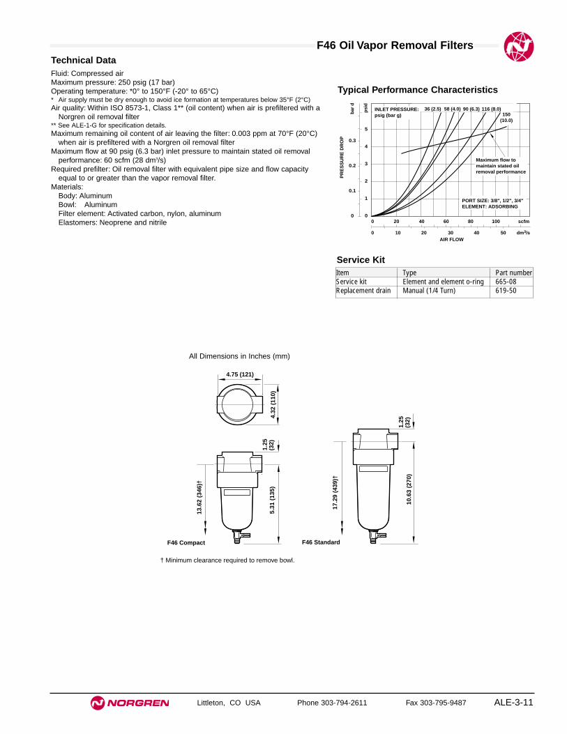
F46 Oil Vapor Removal Filters
Littleton, CO USA Phone 303-794-2611 Fax 303-795-9487 ALE-3-11
All Dimensions in Inches (mm)
Technical DataFluid: Compressed airMaximum pressure: 250 psig (17 bar)Operating temperature: *0° to 150°F (-20° to 65°C)* Air supply must be dry enough to avoid ice formation at temperatures below 35°F (2°C) Air quality: Within ISO 8573-1, Class 1** (oil content) when air is prefiltered with a
Norgren oil removal filter** See ALE-1-G for specification details.Maximum remaining oil content of air leaving the filter: 0.003 ppm at 70°F (20°C)
when air is prefiltered with a Norgren oil removal filterMaximum flow at 90 psig (6.3 bar) inlet pressure to maintain stated oil removal
performance: 60 scfm (28 dm3/s)Required prefilter: Oil removal filter with equivalent pipe size and flow capacity
equal to or greater than the vapor removal filter.Materials:
Body: AluminumBowl: AluminumFilter element: Activated carbon, nylon, aluminumElastomers: Neoprene and nitrile
Typical Performance Characteristics
PR
ES
SU
RE
DR
OP 0.3
0.2
0.1
0
bar
d
5
4
3
2
1
0
psi
d
0 10 20 30 40 50 dm3/sAIR FLOW
0 20 40 60 80 100 scfm
PORT SIZE: 3/8", 1/2", 3/4"ELEMENT: ADSORBING
150(10.0)
Maximum flow to maintain stated oil removal performance
58 (4.0)36 (2.5)INLET PRESSURE:psig (bar g)
90 (6.3) 116 (8.0)
4.32
(11
0)
4.75 (121)
1.25
(32)
10.6
3 (2
70)
F46 Standard
13.6
2 (3
46)†
5.31
(13
5)1.
25(3
2)
17.2
9 (4
39)†
F46 Compact
Service KitItem Type Part numberService kit Element and element o-ring 665-08Replacement drain Manual (1/4 Turn) 619-50
† Minimum clearance required to remove bowl.


Littleton, CO USA Phone 303-794-2611 Fax 303-795-9487 ALE-4-1
Section 4
W07 Series Membrane Dryer 1/4" Port Sizes . . . . . . . . . . . . . . . . . . . . . . . . . . .ALE-4-2
W72 Series Membrane Dryer 1/4" Port Sizes . . . . . . . . . . . . . . . . . . . . . . . . . . .ALE-4-4
W74 Series Membrane Dryer 1/2" Port Sizes . . . . . . . . . . . . . . . . . . . . . . . . . . .ALE-4-6
Membrane DryersRemoves water vapor fromcompressed air providingdewpoint suppression.
Membrane Dryer

Littleton, CO USA Phone 303-794-2611 Fax 303-795-9487
W07M
● Removes water vapor from compressed air providingcondensate-free air at the point of application.
● Provides dewpoint suppression up to 80°F (44°C)depending on air flow through the membrane
● Dewpoint suppression of 20°F (11°C) below the inlettemperature is suitable for most industrialapplications.
● Utilizes the latest membrane technology to achieveoptimal water vapor removal rates.
● W07 available for in-line installation only
● Easy installation, no power required
● Maintenance free with proper prefiltration
● Extremely low pressure drops
W07M Series Membrane Dryer 1/4" Port Size
ALE-4-2
ISO Symbol
Ordering Information. Models listed include NPT threads.
* Maximum flow with 20°F (11°C) dewpoint suppression.
** Differential pressure at 100 psig (7 bar) inlet pressure at stated flows.
Nominal Flow* scfm (dm3/s) Differential Pressure **Port Size Model Outlet Inlet psid (bar) Weight lb (kg)1/4 W07M-2AN-NNA 2 (1.00) 2.2 (1.06) 0.40 (0.028) 0.88 (0.39)
Alternative Models W ★ ★ -M ★ ★ - ★N N ★
Threads SubstituteNPT AISO G parallel G
How to Size a Membrane Dryerl. Enter the application requirements below:
● Maximum air flow required:
● Inlet pressure:
● Dewpoint suppression required:*
2.Select a chart by matching the maximum air flow required to the flowrange in the chart title.
3.Follow the appropriate inlet pressure curve downward until it crossesthe maximum air flow required. Trace a horizontal line to theDEWPOINT SUPPRESSION axis and note the degrees of suppression.Degrees Of Suppression:
4.If the degrees of suppression is less than the application requirement,check the membrane dryer with the next higher flow range. The inletpressure of the smaller membrane dryer may also be increased toprovide greater suppression.
5. If the degrees of suppression is greater than the applicationrequirement, check the membrane dryer with next smaller maximumflow.
* Typically, a dewpoint suppression of 20°F (11°C) below the inlettemperature provides dry air suitable for most industrial applications.

W07M Membrane Dryers
Littleton, CO USA Phone 303-794-2611 Fax 303-795-9487 ALE-4-3
All Dimensions in Inches (mm)Technical DataFluid: Compressed air, prefiltered to 0.01 micron and oil free (ISO 8573-1,
1.7.2 ) with noncycling supply.Maximum pressure: 150 psig (10 bar)Operating temperature: 0° to 175°F (-20° to 80°C)** Air supply must be dry enough to avoid ice formation at temperatures below 35°F (2°C).Nominal flow at 100 psig (7 bar) inlet pressure, 100°F (38°C) inlet temperature, and a
dew point suppression of 20°F (11°C). Flow demand affects dew point suppression.Model W07M-2AN-NNA: 2 scfm (1.00 dm3/s)
MaterialsBody and end caps: Anodized aluminumMembrane: Polymeric materials
NOTE - Required prefiltration: General purpose filter (5 micron element) and an oilremoval filter (0.01 micron particle removal) with equivalent pipe size andflow capacity equal to or greater than the membrane air dryer, (automaticdrains advised).
∅B
A
Model Dimension A Diameter BW07M-2AN-NNA 16.0 (406) 1.18 (30)
Typical Installation. W07 installation uses pipe fittings in conjunction with Miniature 07 Series products
GeneralPurposeFilter
OilRemovalFilter
Membrane Dryer.May be installed vertically or horizontally using pipe nipples and/or elbows.
Regulator
Typical Dew Point Suppression Characteristics
AIR FLOW
0 0.5 1.0 1.5 2.0 2.5 dm3/s
0 1.0 2.0 3.0 4.0 5.0 scfm
PORT SIZE: 1/4"INLET AIR DEW POINT: 100°F (38°C) A B C D E
Inlet Pressurepsig (bar)A = 50 (3.5)B = 75 (5)C = 100 (7)D = 125 (8.5)E = 150 (10)
Membrane Dryer Model W07M-2AN-NNAFlow Range: 0.25 to 2 scfm (0.1 to 1.0 dm3/s)
DE
WP
OIN
T S
UP
PR
ES
SIO
N
°F
80
60
40
20
0
°C
40
30
20
10
0

Littleton, CO USA Phone 303-794-2611 Fax 303-795-9487
W72
● Removes water vapor from compressed air providingcondensate-free air at the point of application.
● Provides dewpoint suppression up to 80°F (44°C)depending on air flow through the membrane
● Dewpoint suppression of 20°F (11°C) or below theinlet temperature is suitable for most industrialapplications.
● Utilizes the latest membrane technology to achieveoptimal water vapor removal rates.
● W72 utilizes the Excelon Quikclamp™ design toprovide in-line or modular installation with 72, 73 and74 Series products.
● Easy installation, no power required
● Maintenance free with proper prefiltration
● Extremely low pressure drops
W72M Series Membrane Dryer 1/4" Port Size
ALE-4-4
ISO Symbol
How to Size a Membrane Dryer
l. Enter the application requirements below:
● Maximum air flow required:
● Inlet pressure:
● Dewpoint suppression required:*
2.Select a chart by matching the maximum air flow required to the flowrange in the chart title.
3.Follow the appropriate inlet pressure curve downward until it crossesthe maximum air flow required. Trace a horizontal line to theDEWPOINT SUPPRESSION axis and note the degrees ofsuppression. Degrees Of Suppression:
4.If the degrees of suppression is less than the application requirement,check the membrane dryer with the next higher flow range. The inletpressure of the smaller membrane dryer may also be increased toprovide greater suppression.
5. If the degrees of suppression is greater than the applicationrequirement, check the membrane dryer with next smaller maximumflow.
* Typically, a dewpoint suppression of 20°F (11°C) below the inlettemperature provides dry air suitable for most industrial applications.
Ordering Information. Models listed include ISO G parallel threads.
* Maximum flow with 20°F (11°C) dewpoint suppression.
** Differential pressure at 100 psig (7 bar) inlet pressure at stated flows.
Nominal Flow* scfm (dm3/s) Differential Pressure **Port Size Model Outlet Inlet psid (bar) Weight lb (kg)1/4 W72M-2AN-NNB 5 (2.40) 5.6 (2.65) 0.32 (0.023) 1.80 (0.82)1/4 W72M-2AN-NNC 10 (4.75) 11.2 (5.27) 0.90 (0.062) 1.86 (0.84)
Alternative Models W ★ ★ -M ★ ★ - ★N N ★
Threads SubstituteNPT AISO G parallel G

W72M Membrane Dryers
Littleton, CO USA Phone 303-794-2611 Fax 303-795-9487 ALE-4-5
All Dimensions in Inches (mm)Technical DataFluid: Compressed air, prefiltered to 0.01 micron and oil free (ISO 8573-1,
1.7.2 ) with noncycling supply.Maximum pressure: 150 psig (10 bar)Operating temperature: 0 to 175°F (-20 to 80°C)** Air supply must be dry enough to avoid ice formation at temperatures below 35°F (2°C).Nominal flow at 7 bar (100 psig) inlet pressure, 100°F (38°C) inlet temperature, and a
dew point suppression of 20°F (11°C). Flow demand affects dew point suppression.Model W72M-2AN-NNB: 5 scfm (2.40 dm3/s)Model W72M-2AN-NNC: 10 scfm (4.75 dm3/s)
MaterialsBody and end caps: Anodized aluminumMembrane: Polymeric materials
NOTE - Required prefiltration: General purpose filter (5 micron element) and an oilremoval filter (0.01 micron particle removal) with equivalent pipe size andflow capacity equal to or greater than the membrane air dryer, (automaticdrains advised).
PORT SIZE: 1/4"INLET AIR DEWPOINT: 100°F (38°C) A B C D E
Inlet Pressurepsig (bar)A = 50 (3.5)B = 75 (5)C = 100 (7)D = 125 (8.5)E = 150 (10)
0 2 4 6 8 10 dm3/s
AIR FLOW
0 4 8 12 16 20 scfm
DE
WP
OIN
T S
UP
PR
ES
SIO
N
°F
80
60
40
20
0
°C
40
30
20
10
0
Membrane Dryer Model W72M-2AN-NNCFlow Range: 1 to 10 scfm (0.5 to 4.75 dm3/s)
0 1 2 3 4 5 dm3/s
AIR FLOW
0 2 4 6 8 10 scfm
PORT SIZE: 1/4"INLET AIR DEWPOINT: 100°F (38°C)
Inlet Pressurepsig (bar)A = 50 (3.5)B = 75 (5)C = 100 (7)D = 125 (8.5)E = 150 (10)
A B C D E
DE
WP
OIN
T S
UP
PR
ES
SIO
N
°F
80
60
40
20
0
°C
40
30
20
10
0
Membrane Dryer Model W72M-2AN-NNBFlow Range: 0.75 to 5 scfm (0.4 to 2.4 dm3/s)
Typical Installation. W72 membrane dryer shown with Excelon
products, Quikclamps and manifold block.
GeneralPurposeFilter
OilRemovalFilter
Excelon Wall Bracket (3 Shown)
ExcelonQuikclamp (5 Shown)
ExcelonManifold Block (1 Shown)
Membrane Dryer.May be installed vertically or horizontally. Pipe nipples and elbow may be used in place of Quikclamps and manifold block.
Regulator
∅B
A
Model Dimension A Diameter BW72M-2AN-NNB 18.0 (457) 1.74 (44)W72M-2AN-NNC 19.0 (483) 1.74 (44)
Typical Dew Point Suppression Characteristics
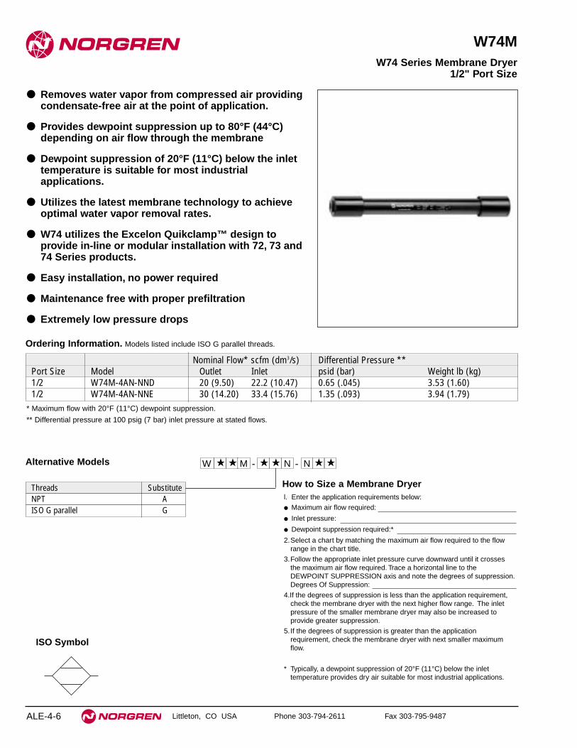
Littleton, CO USA Phone 303-794-2611 Fax 303-795-9487
W74M
● Removes water vapor from compressed air providingcondensate-free air at the point of application.
● Provides dewpoint suppression up to 80°F (44°C)depending on air flow through the membrane
● Dewpoint suppression of 20°F (11°C) below the inlettemperature is suitable for most industrialapplications.
● Utilizes the latest membrane technology to achieveoptimal water vapor removal rates.
● W74 utilizes the Excelon Quikclamp™ design toprovide in-line or modular installation with 72, 73 and74 Series products.
● Easy installation, no power required
● Maintenance free with proper prefiltration
● Extremely low pressure drops
W74 Series Membrane Dryer 1/2" Port Size
ALE-4-6
ISO Symbol
How to Size a Membrane Dryerl. Enter the application requirements below:
● Maximum air flow required:
● Inlet pressure:
● Dewpoint suppression required:*
2.Select a chart by matching the maximum air flow required to the flowrange in the chart title.
3.Follow the appropriate inlet pressure curve downward until it crossesthe maximum air flow required. Trace a horizontal line to theDEWPOINT SUPPRESSION axis and note the degrees of suppression.Degrees Of Suppression:
4.If the degrees of suppression is less than the application requirement,check the membrane dryer with the next higher flow range. The inletpressure of the smaller membrane dryer may also be increased toprovide greater suppression.
5. If the degrees of suppression is greater than the applicationrequirement, check the membrane dryer with next smaller maximumflow.
* Typically, a dewpoint suppression of 20°F (11°C) below the inlettemperature provides dry air suitable for most industrial applications.
Ordering Information. Models listed include ISO G parallel threads.
* Maximum flow with 20°F (11°C) dewpoint suppression.
** Differential pressure at 100 psig (7 bar) inlet pressure at stated flows.
Nominal Flow* scfm (dm3/s) Differential Pressure **Port Size Model Outlet Inlet psid (bar) Weight lb (kg)1/2 W74M-4AN-NND 20 (9.50) 22.2 (10.47) 0.65 (.045) 3.53 (1.60)1/2 W74M-4AN-NNE 30 (14.20) 33.4 (15.76) 1.35 (.093) 3.94 (1.79)
Alternative Models W ★ ★ -M ★ ★ - ★N N ★
Threads SubstituteNPT AISO G parallel G

W74M Membrane Dryers
Littleton, CO USA Phone 303-794-2611 Fax 303-795-9487 ALE-4-7
All Dimensions in Inches (mm)Technical DataFluid: Compressed air, prefiltered to 0,01 micron and oil free (ISO 8573-1,
1.7.2 ) with noncycling supply.Maximum pressure: 150 psig (10 bar)Operating temperature: 0 to 175°F (-20 to 80°C)** Air supply must be dry enough to avoid ice formation at temperatures below 35°F (2°C).Nominal flow at 100 psig (7 bar) inlet pressure,100°F ( 38°C) inlet temperature, and a
dew point suppression of 20°F (11°C). Flow demand affects dew point suppression.Model W74M-4AN-NND: 20 scfm (9.50 dm
3/s)
Model W74M-4AN-NNE: 30 scfm (14.20 dm3/s)
MaterialsBody and end caps: Anodized aluminumMembrane: Polymeric materials
NOTE - Required prefiltration: General purpose filter (5 micron element) and an oilremoval filter (0.01 micron particle removal) with equivalent pipe size andflow capacity equal to or greater than the membrane air dryer, (automaticdrains advised).
PORT SIZE: 1/2"INLET AIR DEWPOINT: 100°F (38°C)
Inlet Pressurepsig (bar)A = 50 (3.5)B = 75 (5)C = 100 (7)D = 125 (8.5)E = 150 (10)
A B C D E
0 5 10 15 20 25 dm3/s
AIR FLOW
0 10 20 30 40 50 60 scfm
DE
WP
OIN
T S
UP
PR
ES
SIO
N
°F
80
60
40
20
0
°C
40
30
20
10
0
Membrane Dryer Model W74M-4AN-NNDFlow Range: 2 to 20 scfm (0.9 to 9.5 dm3/s)
Inlet Pressurepsig (bar)A = 50 (3.5)B = 75 (5)C = 100 (7)D = 125 (8.5)E = 150 (10)
A B C D EPORT SIZE: 1/2"
INLET AIR DEWPOINT: 100°F (38°C)
0 5 10 15 20 25 dm3/s
AIR FLOW
0 10 20 30 40 50 60 scfm
DE
WP
OIN
T S
UP
PR
ES
SIO
N
°F
80
60
40
20
0
°C
40
30
20
10
0
Membrane Dryer Model W74M-4AN-NNEFlow Range: 3 to 30 scfm (1.4 to 14.2 dm3/s)
Typical Installation. W74 membrane dryer shown with Excelon products,
Quikclamps and manifold block.
GeneralPurposeFilter
OilRemovalFilter
Excelon Wall Bracket (3 Shown)
ExcelonQuikclamp (5 Shown)
ExcelonManifold Block (1 Shown)
Membrane Dryer.May be installed vertically or horizontally. Pipe nipples and elbow may be used in place of Quikclamps and manifold block.
Regulator
∅B
A
Model Dimension A Diameter BW74M-4AN-NND 21.0 (533) 2.49 (63)W74M-4AN-NNE 26.0 (660) 2.49 (63)
Typical Dew Point Suppression Characteristics


Littleton, CO USA Phone 303-794-2611 Fax 303-795-9487 ALE-5-A
Regulators
Regulator Overview . . . . . . . . . . . . . . . . . . . . . . . . . . . .ALE-5-B
General Purpose Regulators . . . . . . . . . . . . . . . . . . . . .ALE-5-1
Specialty Regulators (Air or Water, Tube Connection,Factory Preset Pressure, Large Diaphragm, High Relief Flow, Field Adjustable Pressure Limits . . . . .ALE-6-1
Manifolding Regulators . . . . . . . . . . . . . . . . . . . . . . . . .ALE-7-1
Precision and Instrument Regulators . . . . . . . . . . . . . .ALE-8-1
Pilot Regulators . . . . . . . . . . . . . . . . . . . . . . . . . . . . . . .ALE-9-1
Pilot Operated Regulators . . . . . . . . . . . . . . . . . . . . . .ALE-10-1
U.L. Listed Industrial Service Regulators . . . . . . . . . .ALE-11-1
U.L. Listed Beverage Regulators . . . . . . . . . . . . . . . . .ALE-12-1
RegulatorsGeneral Purpose Regulators, SpecialtyRegulators, Manifolding Regulators,Precision and Instrument Regulators,Pilot Regulators, Pilot OperatedRegulators, U.L. Listed Industrial, andBeverage Regulators

Regulator Overview
Littleton, CO USA Phone 303-794-2611 Fax 303-795-9487ALE-5-B
SUPPLYAIR
SUPPLYAIR
OUTLETAIR
PILOT OPERATEDREGULATOR
PILOT OUTPUTLINE
CONVENTIONALPILOTREGULATOR
General purpose regulators have a controlspring which acts on a diaphragm to regulate the airpressure. The rating of this control springdetermines the adjustment range of the regulator.The outlet pressure setting is obtained by turningthe knob (or T handle) clockwise to increasepressure, counter clockwise to decrease pressure.
GENERAL PURPOSE REGULATOR
Knob
Spring rest
Relief seat
Adjusting screw
Adjusting nut
Control spring
Diaphragm
Valve pin
Valve
Valve spring
Bottom plug
1.1 GENERAL OVERVIEW
Regulators ideally provide a constant outletpressure independent of variations in inlet pressureor flow. Regulators are typically used to:i. reduce pressure to the level required for
downstream equipment.ii. limit the force of cylinders.iii. minimize pressure variation at the point of
use.The range of different regulators and
options within each type are wide and varied, buteach can broadly be put into one of 3 categories.• General Purpose Regulators• Pilot Operated Regulators• Application Specific Regulators
1.1.1 General Purpose Regulators:
General purpose regulators are designed to give themaximum flow capacity (for their size) whilemaintaining, to a reasonable accuracy, the outletpressure to the set level.
They are used to control pressures incompressed air line installations to different parts ofmachines or to pneumatic tools and motors.
General purpose regulators are available inrelieving or non-relieving types. Relievingregulators can be adjusted from a high pressure toa low pressure. Even in a dead end situationrelieving regulators will allow the excessdownstream pressure to be exhausted. This causesa loud hissing sound which is perfectly normal.
Non relieving regulators when similarlyadjusted will not allow the downstream pressure toescape. The trapped air will need to be released insome other way, e.g. by operating a downstreamvalve.
1.1.2 Pilot Operated Regulators:
Pilot operated regulators are used in high flowapplications and where access to the main regulatoris limited or difficult. This type of regulator doesnot have a control spring to regulate, instead an airpilot signal is used to control the outlet pressure ofthe main regulator.
This air pilot signal is controlled by a small‘pilot operator’ regulator typically of a precision typeeg 11-018. The flow through the pilot operator isnegligible. The better the pilot, the better theperformance from the main regulator.
The pilot signal for the main regulatorvalve is usually onto a large diaphragm area. Thisresults in pilot operated regulators having betterregulation characteristics than spring operatedgeneral purpose regulators.
Typical Pilot Operation

Regulator Overview
Littleton, CO USA Phone 303-794-2611 Fax 303-795-9487 ALE-5-C
1.1.3 Feedback Pilot Regulators:
For even greater control of the outlet pressure a‘feedback’ pilot operator can be used. Here theoutlet pressure from the pressure critical point inthe system can be fed back to the controlling pilotoperated regulator.
Feedback systems are very responsive todownstream pressure requirements. If performancedoes not meet expectations, consult withApplication Engineering.
Very few applications require feedback andit is usually better to recommend a standard 11-400or a general purpose regulator as a pilot operator.1.1.4 Application Specific Regulators:
Norgren produces a wide range of applicationspecific regulators, each having some enhancedfeature over a general purpose regulator. Some ofthem are listed below.
11-018/-118 - extremely accurate outletpressure control, with high flowfor a precision regulator.Requires oil-free air, pre-filteredto 5µm.
R38 - Instrument regulator, aluminumbody (also available in stainlesssteel to NACE standard), excellentregulation, no constant bleed toatmosphere.
R24 - Good regulation, extremely highrelief capacity. Available inspring or pilot operated versions.
R05/R22 - General purpose regulators withstainless steel bodies to NACEspecification.
R06/R91 - Brass or plastic bodiedspecifically for water. Potable andnon potable water optionsavailable.
Miniature - Generally based around aRegulators modification to a basic R07
including low flow (withimproved regulation), plasticbodied (for water), differentelastomeric materials (for fluidcompatibility)
SUPPLYAIR
OUTLETAIR
SUPPLYAIR
PILOT OPERATEDREGULATOR
FEEDBACKPILOTREGULATOR
PILOTOUTPUTLINE
FEEDBACKLINE
Feedback Pilot Regulator WarningThe feedback line must sense the pilot operated regulator outlet pressureand must be connected before turning on the air supply. If the feedback lineis not connected, the pilot operated regulator outlet pressure will rapidlyincrease to the inlet pressure when the adjusting knob on the pilot regulatoris turned clockwise.
Feedback Operation
Regulator Overview
Littleton, CO USA Phone 303-794-2611 Fax 303-795-9487ALE-5-D
1.2 WHAT CAN WE PRODUCE?
1.2.1 Do Norgren Produce Regulators for InletPressure above 400 psig?
The R38, R43 and R18 can accept inlet pressuresof up to 450 psig. Norgren has higher pressureregulators for industrial gases up to 3000 psi.Consult Application Engineering for details.
1.2.2 Do we Produce Units for Low/HighTemperatures?
Low or high temperature units may be possible insome ranges. Material selection is critical.Consult Air Line for details.Note: changing to viton elastomers does not initself make a unit suitable for higher temperatures.
1.2.3 Can we Produce Sub-Base Regulators?
The USA R40/R41 pilot and feedback pilotregulators are available. A sub-base R06 is alsoavailable.
1.2.4 Can we Produce Manifolding Regulators?
Manifolding regulators are designed to have astraight through primary pressure with secondaryoutlets at 90 degrees. Norgren has:• Excelon 72 R72M - manifold using
Quikclamps.• R30M Plastic R91 style with integral
PIF. Manifold using adapters.• R06 type brass bodied R06, manifold
using fittings.
1.2.5 Do we Produce Liquid (water) Regulators?
Norgren has regulators suitable for liquids,primarily water.
These include plastic bodied miniatureregulators eg R91G/W and 11-044, as well asbrass R06’s and R43’s.
All are suitable for non potable watersome for potable water. Check catalogue sheets fordetails.
A number of units already have theapproval of some water control bodies eg WRC(Water Research Council) UK and NSF USA.
Water regulators can be used with otherliquids but it is necessary to check corrosionresistance and material compatibility. Differences inviscosity may effect performance.
Water regulators can be used on air butnormally have poorer performance characteristicsthan air regulators.
1.2.6 Can we do 11-818 Precision Regulatorswith Gauges?
Yes, we do have some special models, contactApplication Engineering for details.
1.2.7 Can we Produce Back Pressure Regulators?
Yes, a back pressure regulator behaves as a veryprecise relief valve and so controls the rate of relief.With automatic adjustment of its outlet flow toatmosphere the system pressure remainssubstantially constant. These can be produced asspecials.
1.2.8 Can we Produce Reverse Flow Regulators?
Reverse flow regulators allow the outlet pressure toflow back, through the regulator (via an internalcheck valve) when the inlet pressure is switched off.This is important when the regulator is placedbetween a valve and cylinder.
This option is available in Excelon 74, 73and 72 Series and Olympian Plus. The R07, beingan unbalanced valve regulator can also be reverseflowed.
1.3 ADJUSTMENTMECHANISMS
1.3.1 What Different Adjustment Mechanisms areAvailable?
A non-rising knob is the standard adjustmentmechanism for most general purpose regulators. AT-handle will provide added leverage and isstandard for regulators with 250 psig springs. Theyare also a common alternative to a knob inapplications where the operator is wearing gloves,or has greasy hands.
A slotted adjusting screw enables thecustomer to adjust using a screwdriver and ahexagon-headed screw is also available.Handwheels can be fitted to most units and arestandard on precision regulators.
1.3.2 What is the Difference between TamperResistant, Tamper Evident, andTamperproof?
Tamper Resistant: a device which makes alterationsof set pressure difficult.
Units which normally have a T-bar canhave the T-bar replaced by a screw driver slottedadjusting screw over which a metal cap is fitted. Inthis way the set pressure can be protected fromaccidental adjustment.
Units with adjusting knobs are madetamper resistant by preventing the knob being pulledinto its unlocked position for example:-• R07 insert self tapping screw
through the top of the knob.• R72/73/74/64 use tamper resistant kit and
seal with a padlock or sealwire.
Tamper Evident: shows if the set pressurehas been altered by the breaking of a seal.
Tamperproof: something which cannot betampered with at all. It is difficult to describeanything as tamper proof because if someone isintent on making regulator adjustments then theycan always find a way. As a result we do not callour regulators tamper proof.
1.3.3 What Presetting Options are Available?
Most regulators can be ‘set’ in some way, if in doubtcontact Air Line Division as this is generally afactory operation.• Max Set: unit is modified to prevent the
regulator being adjusted above aspecified maximum.
• Min Set: unit is modified to prevent theregulator being adjusted below aspecified minimum.
• Min/Max Set: unit can only be adjusted betweentwo specified upper and lowerunits.
• Preset unit outlet pressure is set and(Factory Set): locked prior to despatch. These
units are not tamper resistant(unless requested).

Regulator Overview
Littleton, CO USA Phone 303-794-2611 Fax 303-795-9487 ALE-5-E
1.4 REGULATORS INAPPLICATIONS
1.4.1 Can the Regulators be Adjusted Outsidethe Recommended Range?
The recommended range is that at which theregulator will perform at its optimum. These are notthe maximum and minimum values. Regulators canbe set outside these limits. For units which cannotbe set outside of a specified range see 1.3.3.
1.4.2 Will Regulators Shut Off?
Yes, screwing the adjustment ‘up’(counterclockwise) closes the valve. It is possible toachieve zero psig with a regulator, however they arenot designed to fulfill this function. If shut off isrequired use a shut off valve.
1.4.3 Will Regulators Work Mounted UpsideDown?
Regulators can be mounted in any orientationwithout affecting their function.
1.4.4 How do you Set a Regulator?
Always set on a rising pressure, i.e. on anincreasing spring load.
To adjust a regulator from 100 psig to 70psig, back the regulator off to below 70 psig andadjust back up to the required pressure.
1.4.5 Can Air Regulators be used on Water?
Generally the answer is no for air regulators withbalanced valves. It is possible with the R06 typewhich does not have a balanced valve and isconsidered dual service. See 1.2.5.
1.4.6 Can we use Air Regulators on otherGases?
Air regulators are generally suitable for use withC02, argon, nitrogen or other inert gases. Howeverunits are designed and tested to compressed airstandards only (unless specified in the literature)and external leakage rates may vary depending onthe gas involved.
Compressed air regulators should neverbe used with flammable or noxious gases eg LPG,hydrogen etc.
1.4.7 Instability - what is it and how can it beprevented?
Instability (humming or whistling) is the rapidcyclic fluctuation of the outlet pressure from aroundthe set pressure.
Instability is ultimately a problemoccurring due to the flow path through the regulatoror system. The usual solution is to change theregulator characteristics by replacing the controlspring with one of a higher rating to increase theforce on the diaphragm or changing the diaphragmmaterial.
There is no magic answer, it is a case oftrial and error in those applications where instabilityoccurs.
1.4.8 What is a Constant Bleed Regulator?
Constant bleed in regulators is designed to provideimproved response. A hissing noise is normal.R24 and 11-018 are all constant bleed regulators.
1.5 PERFORMANCE
1.5.1 Flow Quoted?
Flow characteristic is the measurement of the flowthrough the unit for a given deviation from the setoutlet pressure.
For example, take a regulator and set thepressure at 90 psig under no flow conditions. Asthe flow through the unit is increased then theactual outlet pressure falls away from the setpressure. This is called droop (from set). NormallyNorgren quotes regulator flow measured under thefollowing conditions: Inlet pressure = 150 psig, setpressure = 90 psig and a 15 psig droop from set.
1.5.2 What are Regulation Characteristics?
Regulation characteristics show how the outletpressure from the regulator varies when the inletpressure varies (under constant or no flowconditions).
For example, take a regulator set at 60 psigoutlet pressure, with 150 psig at the inlet. If the inletpressure reduces, ideally the outlet pressure wouldremain the same.
However, in regulators with an unbalancedvalve (eg R07) the outlet pressure actually increasesslightly as the inlet pressure decreases. Inregulators with balanced valves this variation isreduced.
Standard regulators have an acceptabledeviation for most pneumatic application andcustomers tend to be interested in regulationcharacteristics in critical applications only. Wherethis is so, consider using a precision regulator, orconsult Application Engineering about ways toimprove the performance of standard regulators.
1.5.3 What is the Repeatability of a Regulator?
Repeatability can be defined in terms of changes inflow, inlet pressure or time. It is important tounderstand which the customer requires. a. Repeatability with Respect to Changes in
Flow: ie the ability of a regulator to hold aset pressure with increasing or decreasingflow.
b. Repeatability with Respect to TimeChanges: ie the ability of a regulator tohold a set pressure over a time period.
c. Repeatability with Respect to Inlet PressureChanges: ie the ability of a regulator tohold a set pressure with changes in supplypressure.
For more information refer to catalogue graphs, orconsult Application Engineering.
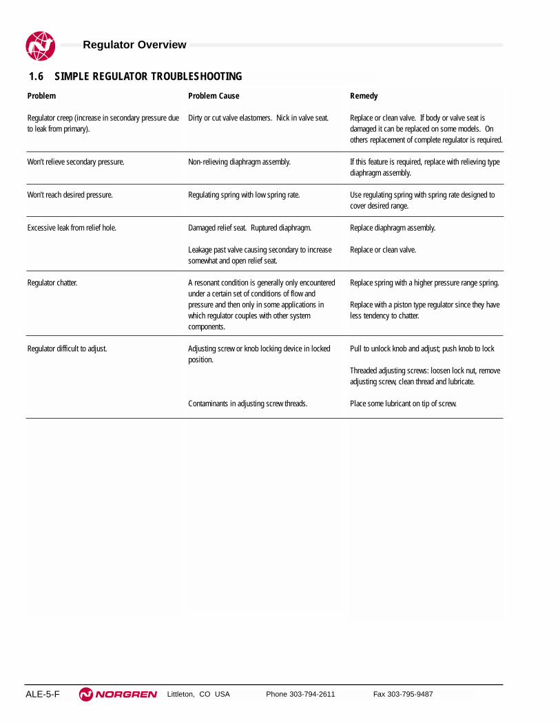
Regulator Overview
Littleton, CO USA Phone 303-794-2611 Fax 303-795-9487ALE-5-F
Problem
Regulator creep (increase in secondary pressure dueto leak from primary).
Won’t relieve secondary pressure.
Won’t reach desired pressure.
Excessive leak from relief hole.
Regulator chatter.
Regulator difficult to adjust.
Problem Cause
Dirty or cut valve elastomers. Nick in valve seat.
Non-relieving diaphragm assembly.
Regulating spring with low spring rate.
Damaged relief seat. Ruptured diaphragm.
Leakage past valve causing secondary to increasesomewhat and open relief seat.
A resonant condition is generally only encounteredunder a certain set of conditions of flow andpressure and then only in some applications inwhich regulator couples with other systemcomponents.
Adjusting screw or knob locking device in lockedposition.
Contaminants in adjusting screw threads.
Remedy
Replace or clean valve. If body or valve seat isdamaged it can be replaced on some models. Onothers replacement of complete regulator is required.
If this feature is required, replace with relieving typediaphragm assembly.
Use regulating spring with spring rate designed tocover desired range.
Replace diaphragm assembly.
Replace or clean valve.
Replace spring with a higher pressure range spring.
Replace with a piston type regulator since they haveless tendency to chatter.
Pull to unlock knob and adjust; push knob to lock
Threaded adjusting screws: loosen lock nut, removeadjusting screw, clean thread and lubricate.
Place some lubricant on tip of screw.
1.6 SIMPLE REGULATOR TROUBLESHOOTING

Littleton, CO USA Phone 303-794-2611 Fax 303-795-9487 ALE-5-1
Section 5
ContentsR07 Miniature General Purpose Filter 1/8" and 1/4" ports . . . . . . .ALE-5-2R46 Miniature, Non-repairable General Purpose Filter
1/4" to 3/8" ports . . . . . . . . . . . . . . . . . . . . . . . . . . . . . . . . . . . . .ALE-5-4R72G/R Excelon General Purpose Filter 1/4" to 3/8" ports . . . . . . .ALE-5-6R73G/R Excelon General Purpose Filter 1/4" to 1/2" ports . . . . . . .ALE-5-8R74G/R Excelon General Purpose Filter 3/8" to 3/4" ports . . . . . .ALE-5-10R64G/R Olympian Plus General Purpose Filter
1/4" to 3/4" ports . . . . . . . . . . . . . . . . . . . . . . . . . . . . . . . . . . . .ALE-5-12R68G Olympian Plus General Purpose Filter
3/4" to 1-1/2" ports . . . . . . . . . . . . . . . . . . . . . . . . . . . . . . . . . . .ALE-5-14R17G General Purpose Filter 3/4" to 1-1/2" ports . . . . . . . . . . . . .ALE-5-16R18G General Purpose Filter 1-1/2" and 2" ports . . . . . . . . . . . . .ALE-5-18
RegulatorsCompressed air regulators areavailable in modular or inlinemodels, in port sizes from 1/8"to 2".
R07 R46 R72G/R R73G/R R74G/R
R18R17R68R64G/R
Product available1st quarter of 2001

See Section ALE-25 for Accessories
Littleton, CO USA Phone 303-794-2611 Fax 303-795-9487
R07
● Compact design
● Full flow gauge ports
● Low torque, non-rising adjusting knob
● Snap action knob locks pressure setting whenpushed in
● Standard relieving models allow reduction of outletpressure even when the system is dead-ended
● Can be disassembled without the use of tools orremoval from the air line
Miniature Series 07 General PurposeRegulator 1/8" and 1/4" Port Sizes
ALE-5-2
ISO Symbols
Relieving Non relieving
Alternative Models
Port Size Substitute1/8" 11/4" 2
Threads SubstitutePTF AISO Rc taper BISO G parallel G
Port Size Model Number Flow† scfm (dm3/s) Weight lbs (kg)1/8" R07-100-RGKA 14 (6.5) 0.31 (0.19)1/4" R07-200-RGKA 15 (7) 0.31 (0.19)
Ordering Information. Models listed include PTF threads, relieving diaphragm, 5 to 100 psig (0.3 to 7 bar) outlet pressure adjustment
range*, with gauge.
Outlet Pressure Adjustment Ranges* Substitute1 to 10 psig (0.1 to 0.7 bar) A5 to 50 psig (0.3 to 3.5 bar) E5 to 100 psig (0.3 to 7 bar) K
Option SubstituteStandard 0Low flow seat 2
Gauges SubstituteWith GWithout N
Diaphragm SubstituteRelieving RNon relieving N
Option SubstituteNot applicable 0
* Outlet pressure can be adjusted to pressures in excess of, and lessthan, those specified. Do not use these units to control pressuresoutside of the specified ranges.
† Approximate flow at 100 psig (7 bar) inlet pressure, 90 psig (6.3 bar) set pressure and a droop of 14.5 psig (1 bar) from set.
- ★★★ ★★ ★ -0 ★R 7

R07 General Purpose Regulators
Littleton, CO USA Phone 303-794-2611 Fax 303-795-9487 ALE-5-3
All Dimensions in Inches (mm)
Technical DataFluid: Compressed airMaximum pressure: 300 psig (20 bar)Operating temperature: -34° to 150°F (-35° to 65°C) ** Air supply must be dry enough to avoid ice formation at temperatures below 2°C (35°F).Typical flow at 150 psig (10 bar) inlet pressure, 90 psig (6.3 bar) set pressure and
a droop of 15 psig (1 bar) from set:1/8" ports: 14 scfm (6.5 dm3/s)1/4" ports: 15 scfm (7 dm3/s)
Gauge ports:1/8" PTF with PTF main ports1/8" ISO Rc with ISO Rc main ports1/8" ISO Rc with ISO G main ports
Materials:Body: ZincBonnet: AcetalValve: Brass/nitrileValve seat: AcetalElastomers: Nitrile
PORT SIZE: 1/4"INLET PRESSURE: 150 psig (10 bar g)RANGE: 5 to 100 psig (0.3 to 7 bar)
FLOW CHARACTERISTICS
0 2 4 6 8 10 dm3/s
AIR FLOW
0 4 8 12 16 20 24 scfm
OU
TL
ET
PR
ES
SU
RE
8
6
4
2
0
bar
g
100
80
60
40
20
0
psi
g
Typical Performance Characteristics
2.13
(54
) 1.50
(38
)
1.63 (41)
1.57 (40)
0.95
(24
) 2.52
(64
)
2.91
(75
)
1.1 (28)
0.73(19)
0.91(23)
Panel mounting hole diameter 1.19" (30 mm)Maximum panel thickness 0.25" (6 mm)
Service KitsItem Type Part number
Service kitRelieving 3407-02Non relieving 3407-01
Service kit includes slip ring, diaphragm, standard valve seat witho-ring, valve, valve spring.

ALE-5-4
See Section ALE-25 for Accessories
Littleton, CO USA Phone 303-794-2611 Fax 303-795-9487
R46
● Reliable pressure regulation at air flows up to 13 scfm (6 dm3/s)
● Compact design and light weight construction
● Wrench flats for easy installation
● Relieving piston design allows reduction ofdownstream pressure when the system is dead-ended
● Choice of left to right or right to left flow
Miniature Non-repairable PressureRegulator 1/4" Port Size
ISO Symbols
Relieving
Ordering Information. Model listed has left to right flow, 5 to 125 psig (0.3 to 8.5 bar) outlet pressure adjustment range*, and PTF threads.
Gauge is not included.
Port Size Model Flow† scfm (dm3/s) Weight lb (kg)1/4" R46-200-RNLA 13 (6) 0.2 (0.09)
† Typical flow with 150 psig (10 bar) inlet pressure, 90 psig (6.3 bar) set pressure and 15 psig (1 bar) droop from set.
* Outlet pressure can be adjusted to pressures in excess of, and less than, those specified. Do not use these units to control pressures outside of the specified ranges.
Alternative Models - ★★★ ★★ ★ -4 ★R 6
Threads SubstitutePTF AISO Rc taper BISO G parallel G
Piston Type SubstituteRelieving R
Outlet Pressure Adjustment Ranges* Substitute5 to 50 psig (0.3 to 3.5 bar) E5 to 125 psig (0.3 to 8.5 bar) L5 to 150 psig (0.3 to 10 bar) M
Port Size Substitute1/4" 2
Gauge SubstituteWith GWithout N
Flow Direction With Knob Upand Gauge Visible SubstituteLeft to Right 00Right to Left 02

ALE-5-5
All Dimensions in Inches (mm)
R46 Miniature, Non-repairable Regulator
Littleton, CO USA Phone 303-794-2611 Fax 303-795-9487
Technical DataFluid: Compressed airMaximum pressure: 250 psig (17 bar)Operating temperature*: -30° to 150°F (-34° to 65°C)*Air supply must be dry enough to avoid ice formation at temperatures below 35°F (2°C).Typical flow with 150 psig (10 bar) inlet pressure, 90 psig (6.3 bar) set pressureand 15 psig (1 bar) droop from from set: 13 scfm (6 dm3/s)Gauge ports:
1⁄8 PTF with PTF main portsRc1/8 with ISO G and ISO Rc main ports
MaterialsBody: ZincKnob: NylonValve: Nitrile compoundValve seat: AcetalElastomers: Nitrile
Typical Performance Characteristics
PORT SIZE: 1/4", INLET PRESSURE: 150 psig (10 bar)RANGE: 5 to 125 psig (0.3 to 8.6 bar)
FLOW CHARACTERISTICS
0 2 4 6 8 10 dm3/s
AIR FLOW
0 4 8 12 16 20 24 scfm
OU
TL
ET
PR
ES
SU
RE
8
6
4
2
0
bar
100
80
60
40
20
0
psi
g
120
PORT SIZE: 1/4"INLET PRESSURE: 100 psig (7 bar)RANGE: 5 to 125 psig (0.3 to 8.6 bar)
FLOW CHARACTERISTICS
0 2 4 6 8 10 dm3/s
AIR FLOW
0 4 8 12 16 20 24 scfm
OU
TL
ET
PR
ES
SU
RE
8
6
4
2
0
bar
100
80
60
40
20
0
psi
g
120
0.75 (19)
1.65
(42
) D
ia.
1.97
(50
)0.
33 (
8)
1.63 (41)
1.88 (48)

See Section ALE-25 for Accessories
Littleton, CO USA Phone 303-794-2611 Fax 303-795-9487
R72G/R
● Excelon design allows in-line or modular installation
● Full flow gauge ports
● Balanced valve design for optimum pressure control
● Push to lock adjusting knob with tamper resistantaccessory
● R72R reverse flow option
● Modular installations with Excelon 72, 73, and 74series can be made to suit particular applications
Excelon 72 Pressure Regulator1/4", 3/8" Port Sizes
ALE-5-6
ISO Symbols
R72G Relieving R72G Non Relieving R72R Relieving R72R Non Relieving
Ordering Information. Models listed include unidirectional flow, PTF threads, knob adjustment, relieving diaphragm, 5 to 150 psig (0.3 to 10 bar)
outlet pressure adjustment range* with gauge.
† Typical flow with 150 psig (10 bar) inlet pressure, 90 psig (6.3 bar) set pressure and a 15 psig (1 bar) droop from set.
Port Size Model Flow† scfm (dm3/s) Weight lb (kg)1/4" R72G-2AK-RMG 70 (33) 0.79 (0.36)3/8" R72G-3AK-RMG 70 (33) 0.79 (0.36)
R 7 2 -★ ★ ★ - ★★ ★ ★
Port Size Substitute1/4" 23/8" 3
Threads SubstitutePTF AISO Rc taper BISO G parallel G
Diaphragm SubstituteRelieving RNon relieving N
Gauge SubstituteWith GWithout N
* Outlet pressure can be adjusted to pressures in excess of, and less than,those specified. Do not use these units to control pressures outside of thespecified ranges.
Adjustment SubstituteKnob KT-bar T
Alternative Models
Outlet Pressure Adjustment Range* Substitute5 to 30 psig (0.3 to 2 bar) C5 to 60 psig (0.3 to 4 bar) F5 to 150 psig (0.3 to 10 bar) M
Flow Type SubstituteStandard GReverse flow R

R72G/R General Purpose Regulators
Littleton, CO USA Phone 303-794-2611 Fax 303-795-9487 ALE-5-7
All Dimensions in Inches (mm)
Technical DataFluid: Compressed airMaximum pressure: 300 psig (20 bar)Operating temperature*: -30° to 150°F (-34° to 65°C)* Air supply must be dry enough to avoid ice formation at temperatures below 35°F (2°C).
Approximate flow at 150 psig (10 bar) inlet pressure, 90 psig (6.3 bar) set pressureand a droop of 15 psig (1 bar) from set: 70 scfm (33 dm3/s)
Gauge ports:1/8" PTF with PTF main ports1/8" ISO Rc with ISO Rc main ports1/8" ISO Rc with ISO G main ports
Materials:Body: ZincBonnet: AcetalValve: BrassElastomers: NitrileBottom plug: Acetal
Typical Performance Characteristics
FLOW CHARACTERISTICS
0 10 20 30 40 50 dm3/s
AIR FLOW
0 20 40 60 80 100 120 scfm
OU
TL
ET
PR
ES
SU
RE
8
6
4
2
0
bar
g
100
80
60
40
20
0
psi
g
PORT SIZE: 1/4"INLET PRESSURE: 150 psig (10 bar g)
RANGE: 5 to 150 psig (0.3 to 10 bar)
1.97 (50) 1.97 (50)
2.48 (63)
1.89
(48
)
1.38
(35
)
1.89
(48
)
1.38
(35
)
2.88
(73
)1.
31 (
33)
4.03
(10
2)1.
31 (
33)
1.01
(26
)
1.01
(26
)
Panel mounting hole diameter: 1.57" (40 mm)
Maximum panel thickness: 0.16" (4 mm)
Service KitsItem Type Part Number
Service kitRelieving 4381-500Non relieving 4381-501
Service kit includes diaphragm assembly, valveassembly, valve spring and o-rings.
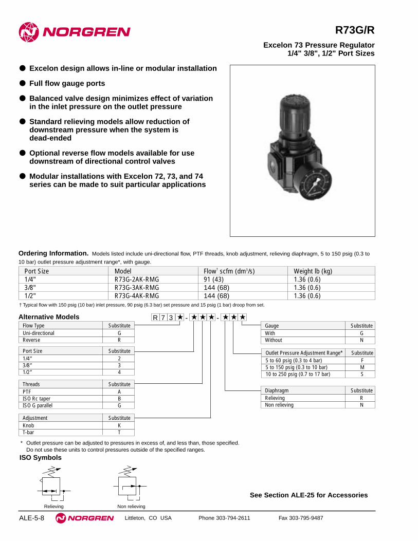
See Section ALE-25 for Accessories
Littleton, CO USA Phone 303-794-2611 Fax 303-795-9487
R73G/R
● Excelon design allows in-line or modular installation
● Full flow gauge ports
● Balanced valve design minimizes effect of variationin the inlet pressure on the outlet pressure
● Standard relieving models allow reduction ofdownstream pressure when the system is dead-ended
● Optional reverse flow models available for usedownstream of directional control valves
● Modular installations with Excelon 72, 73, and 74series can be made to suit particular applications
Excelon 73 Pressure Regulator1/4" 3/8", 1/2" Port Sizes
ALE-5-8
ISO Symbols
Relieving Non relieving
Alternative Models
Ordering Information. Models listed include uni-directional flow, PTF threads, knob adjustment, relieving diaphragm, 5 to 150 psig (0.3 to
10 bar) outlet pressure adjustment range*, with gauge.
R 7 3 -★ ★ ★ - ★★ ★ ★
Threads SubstitutePTF AISO Rc taper BISO G parallel G
Adjustment SubstituteKnob KT-bar T
Port Size Model Flow† scfm (dm3/s) Weight lb (kg)1/4" R73G-2AK-RMG 91 (43) 1.36 (0.6)3/8" R73G-3AK-RMG 144 (68) 1.36 (0.6)1/2" R73G-4AK-RMG 144 (68) 1.36 (0.6)
Diaphragm SubstituteRelieving RNon relieving N
Gauge SubstituteWith GWithout N
Outlet Pressure Adjustment Range* Substitute5 to 60 psig (0.3 to 4 bar) F5 to 150 psig (0.3 to 10 bar) M10 to 250 psig (0.7 to 17 bar) S
Port Size Substitute1/4" 23/8" 31/2" 4
† Typical flow with 150 psig (10 bar) inlet pressure, 90 psig (6.3 bar) set pressure and 15 psig (1 bar) droop from set.
Flow Type SubstituteUni-directional GReverse R
* Outlet pressure can be adjusted to pressures in excess of, and less than, those specified.Do not use these units to control pressures outside of the specified ranges.

R73G/R General Purpose Regulators
Littleton, CO USA Phone 303-794-2611 Fax 303-795-9487 ALE-5-9
All Dimensions in Inches (mm)
Technical DataFluid: Compressed airMaximum pressure: 300 psig (20 bar)Operating temperature*: -30° to 175°F (-34° to 80°C)*Air supply must be dry enough to avoid ice formation at temperatures below 35°F (2°C).
Typical flow with 150 psig (10 bar) inlet pressure, 90 psig (6.3 bar) set pressureand 15 psig (1 bar) droop from from set: 144 scfm (68 dm3/s)
Gauge ports:1⁄4 PTF with PTF main portsRc1/4 with ISO Rc main portsRc1/8 with ISO G main ports
MaterialsBody: AluminumBonnet: Aluminum or ZincValve: BrassElastomers: NitrileBottom plug: Acetal
Typical Performance Characteristics
0 20 40 60 80 100 dm3/s
AIR FLOW
0 40 80 120 160 200 scfm
OU
TL
ET
PR
ES
SU
RE
8
6
4
2
0
bar
100
80
60
40
20
0
psi
g PORT SIZE: 3/8"INLET PRESSURE: 150 psig (10 bar)RANGE: 5 to 150 psig (0.3 to 10 bar)
FLOW CHARACTERISTICS
0 10 20 30 40 50 dm3/s
AIR FLOW
0 20 40 60 80 100 scfm
OU
TL
ET
PR
ES
SU
RE
6
4
2
0
bar
100
80
60
40
20
0 p
sig PORT SIZE: 3/8"
INLET PRESSURE: 100 psig (7 bar)RANGE: 5 to 150 psig (0.3 to 10 bar)
FLOW CHARACTERISTICS
2.68 (68)
2.45
(62)1.
22 (3
1)
2.20
(56)
1.54
(39)
3.80
(96)
1.22
(31)
4.04
(103
)
0.45
(12)
2.00 (50)
Panel mounting hole diameter: 1.89" (48 mm)
Panel thickness: 0.06" to 0.25" (2 to 6 mm)
Service kit includes diaphragm assembly, valve assembly,valve spring, bottom plug o-ring.
Service KitsItem Type Part NumberService kit Relieving 4381-600
Non-relieving 4381-601

See Section ALE-25 for Accessories
Littleton, CO USA Phone 303-794-2611 Fax 303-795-9487
R74G/R
● Excelon design allows in-line or modular installation
● Full flow gauge ports
● Balanced valve design minimizes effect of variationin the inlet pressure on the outlet pressure
● Standard relieving models allow reduction ofdownstream pressure when the system is dead-ended
● Optional reverse flow models available for usedownstream of directional control valves
● Modular installations with Excelon 72, 73, and 74series can be made to suit particular applications
Excelon 74 Pressure Regulator 3/8", 1/2", 3/4" Port Sizes
ALE-5-10
Alternative Models
Ordering Information. Models listed include uni-directional flow, PTF threads, knob adjustment, relieving diaphragm, 5 to 150 psig
(0.3 to 10 bar) outlet pressure adjustment range*,with gauge.
R 7 4 -★ ★ ★ - ★★ ★ ★
Threads SubstitutePTF AISO Rc taper BISO G parallel G
Adjustment SubstituteKnob KT-bar T
Port Size Model Flow† scfm (dm3/s) Weight lb (kg)3/8" R74G-3AK-RMG 208 (98) 1.80 (0.82)1/2" R74G-4AK-RMG 220 (105) 1.77 (0.80)3/4" R74G-6AK-RMG 220 (105) 1.73 (0.78)
Diaphragm SubstituteRelieving RNon relieving N
Gauge SubstituteWith GWithout N
Outlet PressureAdjustment Range* Substitute5 to 60 psig (0.3 to 4 bar) F5 to 150 psig (0.3 to 10 bar) M10 to 250 psig (0.7 to 17 bar)** S
Port Size Substitute3/8" 31/2" 43/4" 6
† Typical flow with 150 psig (10 bar) inlet pressure, 90 psig (6.3 bar) set pressure and a droop of 15 psig (1 bar) from set.
Flow Type SubstituteUni-directional GReverse R
* Outlet pressure can be adjusted to pressures in excess of, and less than, those specified. Do not use these units to controlpressures outside of the specified ranges.
** Units with 250 psig (17 bar) outlet pressure range are available only with the T-bar adjustment; therefore substitute T at the 7thposition and S at the 9th position.
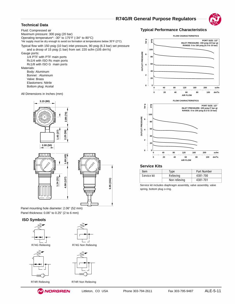
R74G/R General Purpose Regulators
Littleton, CO USA Phone 303-794-2611 Fax 303-795-9487 ALE-5-11
All Dimensions in Inches (mm)
Technical DataFluid: Compressed airMaximum pressure: 300 psig (20 bar)Operating temperature*: -30° to 175°F (-34° to 80°C)*Air supply must be dry enough to avoid ice formation at temperatures below 35°F (2°C).
Typical flow with 150 psig (10 bar) inlet pressure, 90 psig (6.3 bar) set pressureand a droop of 15 psig (1 bar) from set: 220 scfm (105 dm3/s)
Gauge ports:1/4 PTF with PTF main portsRc1/4 with ISO Rc main portsRc1/8 with ISO G main ports
Materials:Body: AluminumBonnet : AluminumValve: BrassElastomers: NitrileBottom plug: Acetal
ISO Symbols
R74G Relieving R74G Non Relieving
R74R Relieving R74R Non Relieving
Typical Performance Characteristics
0 20 40 60 80 100 dm3/s
AIR FLOW
0 40 80 120 160 200 scfm
OU
TL
ET
PR
ES
SU
RE
6
4
2
0
bar
g
100
80
60
40
20
0 p
sig
PORT SIZE: 1/2"INLET PRESSURE: 100 psig (7 bar g)RANGE: 5 to 150 psig (0.3 to 10 bar)
FLOW CHARACTERISTICS
0 20 40 60 80 100 dm3/sAIR FLOW
0 40 80 120 160 200 scfm
OU
TL
ET
PR
ES
SU
RE
6
4
2
0
bar
g
100
80
60
40
20
0
psi
g PORT SIZE: 1/2"INLET PRESSURE: 150 psig (10 bar g)
RANGE: 5 to 150 psig (0.3 to 10 bar)
FLOW CHARACTERISTICS
2.89
(74
)2.
20 (
56)
1.45
(37
)
3.15 (80)
1.69
(43
)4.
98 (
127)
2.00 (50)
5.95
(15
1)
1.24
(31
)
Service kit includes diaphragm assembly, valve assembly, valvespring, bottom plug o-ring.
Service KitsItem Type Part NumberService kit Relieving 4381-700
Non relieving 4381-701
Panel mounting hole diameter: 2.06" (52 mm)
Panel thickness: 0.06" to 0.25" (2 to 6 mm)

See Section ALE-25 for Accessories
Littleton, CO USA Phone 303-794-2611 Fax 303-795-9487
R64G/R
● Olympian Plus plug in design
● High flow general purpose regulator
● Push to lock adjusting knob with tamper resistantoption
● Mount in any orientation
Olympian Plus Regulator1/4", 3/8", 1/2", 3/4" Port Sizes
ALE-5-12
ISO Symbols
Relieving Non Relieving
Ordering Information. Models listed include unidirectional flow, PTF threads, knob adjustment, relieving diaphragm, 5 to 150 psig (0.3 to 10 bar) outlet
pressure adjustment range* with gauge.
† Typical flow with 150 psig (10 bar) inlet pressure, 90 psig (6.3 bar) set pressure and a 15 psig (1 bar) droop from set.
For replacement regulator (without yoke) substitute ‘N’ at the 5th and 6th digits eg: R64G-NNK-RMN.
Port Size Model Flow† scfm (dm3/s) Weight lb (kg)1/4" R64G-2AK-RMG 74 (35) 3.42 (1.54)3/8 " R64G-3AK-RMG 170 (80) 3.38 (1.52)1/2" R64G-4AK-RMG 254 (120) 3.31 (1.49)3/4 " R64G-6AK-RMG N.A. 4.11 (1.85)
R 6 4 -★ ★ ★ - ★★ ★ ★
Port Size Substitute1/4" 23/8" 31/2" 43/4" 6
Threads SubstitutePTF AISO Rc taper BISO G parallel G
Diaphragm SubstituteRelieving RNon relieving N
Gauge SubstituteWith GWithout N
* Outlet pressure can be adjusted to pressures in excess of,and less than, those specified. Do not use these units tocontrol pressures outside of the specified ranges.
** Units with 250 psig (17 bar) outlet pressure range areavailable only with the T-bar adjustment; therefore substituteT at the 7th digit and S at the 9th position.
Adjustment SubstituteKnob KT-bar T
Alternative Models
Outlet Pressure Adjustment Range* Substitute5 to 60 psig (0.3 to 4 bar) F5 to 150 psig (0.3 to 10 bar) M10 to 250 psig (0.7 to 17 bar) S**
Flow Type SubstituteStandard GReverse flow R

R64G/R General Purpose Regulators
Littleton, CO USA Phone 303-794-2611 Fax 303-795-9487 ALE-5-13
All Dimensions in Inches (mm)
Technical DataFluid: Compressed airMaximum pressure: 250 psig (17 bar)Operating temperature*: -30° to 175°F (-34° to 80°C)* Air supply must be dry enough to avoid ice formation at temperatures below 35°F (2°C).
Typical flow at 150 psig (10 bar) inlet pressure, 90 psig (6.3 bar) set pressure anda droop of 15 psig (1 bar) from set: 254 scfm (120 dm3/s)
Gauge Ports:1/8" PTF with PTF main ports1/8" ISO Rc with ISO Rc main ports1/8" ISO Rc with ISO G main ports
Materials:Body: ZincBonnet: AluminiumYoke: ZincValve: BrassElastomers: Synthetic rubber
Typical Performance Characteristics
INLET PRESSURE: 150 psig (10 bar g)RANGE: 5 to 150 psig (0.3 to 10 bar)
FLOW CHARACTERISTICS
0 40 80 120 160 200 dm3/s
AIR FLOW
0 80 160 240 320 400 scfm
OU
TL
ET
PR
ES
SU
RE
8
6
4
2
0
bar
g
100
80
60
40
20
0
psi
g
PORT SIZE: 1/2"
4.13 (105)**
1.46
(37
)
2.91
(74
)
8.27
(21
0)†
5.24
(13
3)†
6.93
(17
6)†
Panel mounting hole diameter: 2.06" (52 mm)Maximum panel thickness: 0.25" (6 mm)
† Reduces by 4 mm with knob in locked position. Add 37 mm for unit with ‘T’handle.
** 6.18" (157 mm) for models with 3/4" ports
Service KitsItem Type Part Number
Service kitRelieving 4381-200Non relieving 4381-201
Service kit includes port and bottom plug ‘O’ rings, valve assembly,valve spring and diaphragm.

Littleton, CO USA Phone 303-794-2611 Fax 303-795-9487
R68G
● Olympian plug in design
● Robust and compact
● High flow unit with large valve and diaphragm
● Push to lock adjusting knob with tamper resistantoption
●
Excellent flow and regulation characteristics
Olympian Regulator3/4", 1", 1-1/4",1-1/2" Port Sizes
ALE-5-14
ISO Symbol
Relieving Non Relieving
Port Size Model Weight lb (kg)3/4" R68G-6AK-RLN 4.53 (2.04)1" R68G-8AK-RLN 4.53 (2.04)1-1/4" R68G-AAK-RLN 4.62 (2.08)1-1/2" R68G-BAK-RLN 4.71 (2.12)
R 6 8 -G ★ ★ - ★★ ★ ★Alternative Models
Ordering Information. Models listed include PTF threads, knob adjustment, relieving diaphragm, 5 to 120 psig (0.4 to 8 bar) outlet pressure
adjustment range* without gauge.
Port Size Substitute3/4" 61" 81-1/4" A1-1/2" BNone N
Threads SubstitutePTF AISO Rc taper BISO G parallel GNone N
Option SubstituteAdjusting knob KT-bar T
Gauge SubstituteWith GWithout N
Type SubstituteRelieving RNon relieving NRelieving, Viton option FNon relieving, Viton option E
Outlet Pressure Adjustment Range* Substitute0 to 60 psig (0 to 4 bar) F5 to 120 psig (0.4 to 8 bar) L10 to 250 psig (0.7 to 17 bar) S**
* Outlet pressure can be adjusted to pressures in excess of, and lessthan, those specified. Do not use these units to control pressuresoutside of the specified ranges.
** Units with 250 psig (17 bar) adjustment range are available only withthe T-bar adjustment; therefore substitute T at the 7th digit and S atthe 9th position.
68 Series products are available 1st quarter of 2001. Visit www.norgren.com for the latestdata on this series.

R68G General Purpose Regulators
Littleton, CO USA Phone 303-794-2611 Fax 303-795-9487 ALE-5-15
All Dimensions in Inches (mm)
Technical DataFluid: Compressed air
Maximum pressure:
290 psig (20 bar)
Operating temperature*:
0° to 175°F (-20° to 80°C)* Air supply must be dry enough to avoid ice formation at temperatures below 35°F (2°C).
Typical flow at 150 psig (10 bar) inlet pressure, 95 psig (6.3 bar)
(90 psig) set pressure and a droop of 15 psig (1 bar) from set:
381
scfm (180 dm3/s) TBA from Lab Tests
Gauge ports: PTF 1/8
Typical Performance CharacteristicsFLOW CHARACTERISTICS
0 50 100 150 200 250 dm3/s
AIR FLOW
0 100 200 300 400 500 600 scfm
8
6
4
2
0
PR
ES
SU
RE
DR
OP
bar
g
100
80
60
40
20
0
psi
g
UNPORTEDINLET PRESSURE - 150 psig (10 bar g)RANGE: 5 to 120 psig (0.4 to 8 bar)
* Reduces by 0.16" (4 mm) with knob in lockedposition. Add 1.46" (37 mm) for unit with T-handle
† Minimum clearance required to remove unit.
7.76
(19
7)*
2.44
(62
)
2.13
(54
)
4.12 (125)
8.70
(22
1)*†
68 Series products are available 1st quarter of 2001. Visit www.norgren.com for the latestdata on this series.

See Section ALE-25 for Accessories
Littleton, CO USA Phone 303-794-2611 Fax 303-795-9487
R17
● Accurate and quick response to changes in flow demand and line pressure variations
● Balanced valve minimizes effect of changes in inletpressure on outlet pressure
● Standard relieving models allow reduction of outletpressure even when the system is dead-ended
● Full flow gauge ports
● Low torque, non-rising adjusting knob
● Integral locking device on knob adjustment
● Can be serviced without removal from the air line
17 Series General Purpose Regulator3/4", 1", 1-1/4", and 1-1/2" Port Sizes
ALE-5-16
Relieving Non relieving
ISO Symbols
† Typical flow with 150 psig (10 bar) inlet pressure, 90 psig (6.3 bar) set pressure and a 15 psig (1 bar) droop from set.
* Outlet pressure can be adjusted to pressures in excess of, and less than, those specified. Do not use these units to control pressures outside of the specified ranges.
Ordering Information. Models listed are knob adjustment, relieving type with gauge, 5 to 125 psig (0.3 to 8.5 bar) outlet pressure
adjustment range*, and PTF threads.
Port Size Model Number Flow† scfm (dm3/s) Weight lbs (kg)3/4" R17-600-RGLA 440 (208) 2.31 (1.05)1" R17-800-RGLA 480 (227) 2.02 (0.921-1/4" R17-A00-RGLA 400 (189) 2.68 (1.22)1-1/2" R17-B00-RGLA 440 (208) 2.59 (1.18)
Alternative Models - ★★★ ★★ ★ -1 ★R 7
Threads SubstitutePTF AISO Rc taper BBSPP (1-1/2" ported units only) CISO G parallel (not available with1-1/2" Gported units)
Diaphragm SubstituteRelieving RNon relieving N
Outlet Pressure Adjustment Ranges* Substitute5 to 50 psig (0.3 to 3.5 bar) E5 to 125 psig (0.3 to 8.5 bar) L10 to 250 psig (0.7 to 17 bar) S
Port Size Substitute3/4" 61" 81-1/4" A1-1/2" B
Gauge SubstituteWith GWithout N
Option SubstituteNot applicable 0
Adjustment SubstituteKnob 0T-bar 1

R17 General Purpose Regulators
Littleton, CO USA Phone 303-794-2611 Fax 303-795-9487 ALE-5-17
All Dimensions in Inches (mm)
Technical DataFluid: Compressed airMaximum pressure: 300 psig (20 bar)Operating temperature: -30° to 175°F (-34° to 80°C)** Air supply must be dry enough to avoid ice formation at temperatures 35°F (2°C).
Typical flow at 150 psig (10 bar) inlet pressure, 90 psig (6.3 bar) set pressure, anda droop of 15 psig (1 bar) from set: 480 scfm (227 dm3/s)
Gauge ports:1/4" PTF with PTF main portsR1/4 with ISO Rc, ISO G, and BSPP main ports
MaterialsBody: AluminumBonnet: AluminumBottom plug: AcetalValve: Aluminum and nylonElastomers: Nitrile
Typical Performance Characteristics
PORT SIZE: 1"SPRING RANGE: 5 to 125 psig (0.3 TO 8.5 bar)
INLET PRESSURE: 150 psig (10 bar)
0 40 80 120 160 200 dm3/sAIR FLOW
0 80 160 240 320 400 scfm
OU
TL
ET
PR
ES
SU
RE
8
6
4
2
0
bar
g
100
80
60
40
20
0
psi
g
2.00(51)
2.92
(74)
2.00(51)
2.25(57)
4.25 (108)
2.92
(74)
1.22
(31)
4.71
(120
)
7.09
(180
)
1.22
(31)
5.69
(145
)
8.07
(205
)
Panel mounting hole diameter: 2.28" (58 mm)Panel thickness: 0.06" to 0.16" (2 to 4 mm)
Service KitsItem Type Part numberService kit Relieving 5578-02
Non relieving 5578-01Service kit contains, diaphragm, all o-rings, valve, and valve spring.

ALE-5-18
See Section ALE-25 for Accessories
Littleton, CO USA Phone 303-794-2611 Fax 303-795-9487
R18
● The R18 with the conventional integral pilot providesgood pressure regulation, rapid response tochanging flow demands, and excellent stability.
● The R18 with the feedback integral pilot providessuperior pressure regulation under changing flowdemands where changes in flow demand are notsudden or cyclic.
● Balanced valve minimizes effect of changes in inletpressure on outlet pressure
● Constant bleed feature in pilot regulator providesquick response and minimum dead-band
● Exceptionally high relief flow
● Full flow gauge ports
● Low torque, non-rising adjusting knob
● Integral locking device on knob adjustment
18 Series General Purpose Pressure Regulator1-1/2" and 2" Port Sizes
R18 with Conventional Pilot Regulator R18 with Feedback Pilot Regulator
ISO Symbols
Alternative Models- ★★★ ★★ ★ -1 ★R 8
Port Threads SubstitutePTF AISO Rc taper BISO G parallel G
Diaphragm SubstituteRelieving RNon relieving N
Outlet Pressure Adjustment Ranges* Substitute5 to 50 psig (0.3 to 3.5 bar) E5 to 125 psig (0.3 to 8.5 bar) L10 to 250 psig (0.7 to 17 bar) S
Port Size Substitute1-1/2" B2" C
Gauge SubstituteWith GWithout N
Pilot Regulator Type SubstituteR40 Conventional 05R41 Feedback ** 06
Ordering Information. Models listed include R40 conventional integral pilot, relieving diaphragm, with gauge, 5 to 125 psig (0.3 to 8.5 bar) outlet pressure adjustment range*, and PTF threads.
Port Size Model Flow† scfm (dm3/s) Weight lb (kg)1-1/2" R18-B05-RGLA 2000 (944) 8.48 (3.85)2" R18-C05-RGLA 2000 (944) 8.27 (3.75)
* Outlet pressures can be adjusted to pressures in excess or, and less than, thosespecified. Do not use these units to control pressures outside of the specified ranges.
** Requires relieving diaphragm and 250 psig (17 bar) spring (R in 7th position and S in 9th position) e.g. R18-B06-R N S G .
† Typical flow with 100 psig (0.7 bar) inlet pressure, 90 psig (6.3 bar) set pressure and a droop of 15 psig (1 bar) from set.
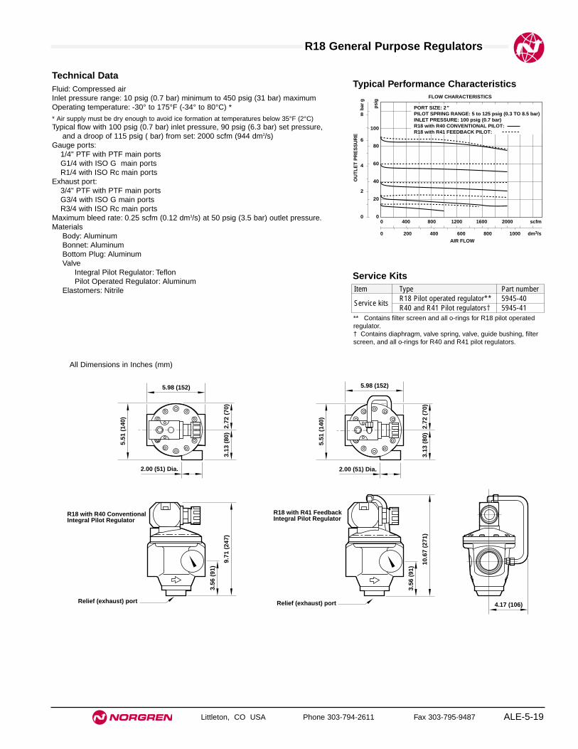
ALE-5-19
All Dimensions in Inches (mm)
R18 General Purpose Regulators
Littleton, CO USA Phone 303-794-2611 Fax 303-795-9487
Technical DataFluid: Compressed airInlet pressure range: 10 psig (0.7 bar) minimum to 450 psig (31 bar) maximumOperating temperature: -30° to 175°F (-34° to 80°C) *
* Air supply must be dry enough to avoid ice formation at temperatures below 35°F (2°C)Typical flow with 100 psig (0.7 bar) inlet pressure, 90 psig (6.3 bar) set pressure,
and a droop of 115 psig ( bar) from set: 2000 scfm (944 dm3/s)Gauge ports:
1/4" PTF with PTF main portsG1/4 with ISO G main portsR1/4 with ISO Rc main ports
Exhaust port:3/4" PTF with PTF main portsG3/4 with ISO G main portsR3/4 with ISO Rc main ports
Maximum bleed rate: 0.25 scfm (0.12 dm3/s) at 50 psig (3.5 bar) outlet pressure.Materials
Body: AluminumBonnet: AluminumBottom Plug: AluminumValve
Integral Pilot Regulator: TeflonPilot Operated Regulator: Aluminum
Elastomers: Nitrile
Typical Performance Characteristics
PORT SIZE: 2"PILOT SPRING RANGE: 5 to 125 psig (0.3 TO 8.5 bar)INLET PRESSURE: 100 psig (0.7 bar)R18 with R40 CONVENTIONAL PILOT:R18 with R41 FEEDBACK PILOT:
FLOW CHARACTERISTICS
0 200 400 600 800 1000 dm3/sAIR FLOW
0 400 800 1200 1600 2000 scfm
OU
TL
ET
PR
ES
SU
RE
8
6
4
2
0
bar
g
100
80
60
40
20
0
psi
g
5.51
(14
0)
2.72
(70
)3.
13 (
80)
9.71
(24
7)
3.56
(91
)
5.98 (152)
2.00 (51) Dia.
R18 with R40 ConventionalIntegral Pilot Regulator
Relief (exhaust) port
5.51
(14
0)
2.72
(70
)3.
13 (
80)
10.6
7 (2
71)
3.56
(91
)
5.98 (152)
2.00 (51) Dia.
4.17 (106)
R18 with R41 FeedbackIntegral Pilot Regulator
Relief (exhaust) port
Service KitsItem Type Part number
Service kitsR18 Pilot operated regulator** 5945-40R40 and R41 Pilot regulators† 5945-41
** Contains filter screen and all o-rings for R18 pilot operatedregulator.† Contains diaphragm, valve spring, valve, guide bushing, filterscreen, and all o-rings for R40 and R41 pilot regulators.

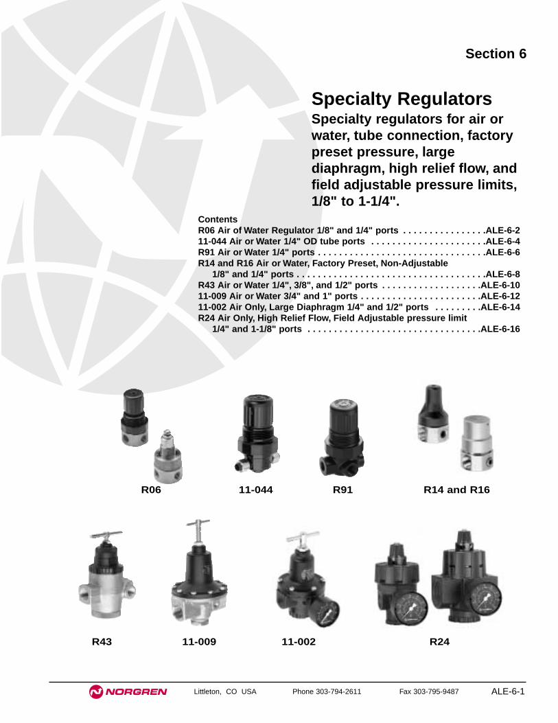
Littleton, CO USA Phone 303-794-2611 Fax 303-795-9487 ALE-6-1
Section 6
ContentsR06 Air of Water Regulator 1/8" and 1/4" ports . . . . . . . . . . . . . . . .ALE-6-211-044 Air or Water 1/4" OD tube ports . . . . . . . . . . . . . . . . . . . . . .ALE-6-4R91 Air or Water 1/4" ports . . . . . . . . . . . . . . . . . . . . . . . . . . . . . . . .ALE-6-6R14 and R16 Air or Water, Factory Preset, Non-Adjustable
1/8" and 1/4" ports . . . . . . . . . . . . . . . . . . . . . . . . . . . . . . . . . . . .ALE-6-8R43 Air or Water 1/4", 3/8", and 1/2" ports . . . . . . . . . . . . . . . . . . .ALE-6-1011-009 Air or Water 3/4" and 1" ports . . . . . . . . . . . . . . . . . . . . . . .ALE-6-12 11-002 Air Only, Large Diaphragm 1/4" and 1/2" ports . . . . . . . . .ALE-6-14R24 Air Only, High Relief Flow, Field Adjustable pressure limit
1/4" and 1-1/8" ports . . . . . . . . . . . . . . . . . . . . . . . . . . . . . . . . .ALE-6-16
Specialty RegulatorsSpecialty regulators for air orwater, tube connection, factorypreset pressure, largediaphragm, high relief flow, andfield adjustable pressure limits,1/8" to 1-1/4".
R06 11-044 R91 R14 and R16
R43 11-009 11-002 R24

See Section ALE-25 for Accessories
ALE-6-2 Littleton, CO USA Phone 303-794-2611 Fax 303-795-9487
R06
● Compact design, corrosion resistant construction
● Brass body with choice of plastic or brass bonnet
● Plastic bonnet equipped with low torque, non-risingpressure adjusting knob. Snap action knob lockspressure setting when pushed in
● Brass bonnet equipped with pressure adjustingscrew
● Non-relieving models for air and water service
● Relieving models for air service allow reduction ofoutlet pressure even when the system is dead-ended
● Can be disassembled without the use of tools orremoval from the air or water line
Miniature Brass Body Regulator Water and Compressed Air Service
1/8" and 1/4" PTF Port Sizes
ISO Symbols
Relieving Non relieving
Alternative Models0R 6 ★ ★ ★ ★★ -★ ★ -
Port Size Substitute1/8" 11/4" 2
Threads SubstitutePTF A
Outlet Pressure Adjustment Range† Substitute1 to 10 psig (0.1 to 0.7 bar) A5 to 50 psig (0.3 to 3.5 bar) E5 to 100 psig (0.3 to 7 bar) K
Gauges SubstituteWith GWithout N
Diaphragm SubstituteRelieving RNon relieving N
Bonnet SubstitutePlastic 21Brass 22
† Outlet pressure can be adjusted to pressures in excess of, and less than, those specified. Do not use these units to control pressures outside of the specified ranges.
Ordering Information. Models listed include PTF threads, plastic bonnet with knob adjustment, non-relieving diaphragm, 5 to 100 psig (0.3 to 7 bar)outlet pressure adjustment range†, and without gauge.
Port Model Flow* scfm (dm3/s) Flow** gpm (lpm) Weight lb (kg)1/8" PTF R06-121-NNKA 12 (5.7) 1.3 (4.9) 0.2 (0.09)1/4" PTF R06-221-NNKA 12 (5.7) 1.3 (4.9) 0.2 (0.09)
* Approximate flow with 100 psig (7 bar) inlet pressure, 90 psig (6.3 bar) set pressure and a 15 psig (1 bar) droop from set.** Approximate flow with100 psig ( 7 bar) inlet pressure, 60 psig (4 bar) set pressure and a 15 psig (1 bar) droop from set.

ALE-6-3
All Dimensions in Inches (mm)
Littleton, CO USA Phone 303-794-2611 Fax 303-795-9487
R06 Special Purpose Regulators
Technical DataFluid: Water and compressed airMaximum pressure: 400 psig (27 bar)Operating temperature
Water service: 35° to 150°F (2° to 65°C)Air service: -30° to 150°F (-34° to 65°C) *
* Air supply must be dry enough to avoid ice formation at temperatures below 35°F (2°C).
Typical flow for water service at 100 psig (7 bar) inlet pressure, 60 psig (4 bar) setpressure and a droop of 15 psig (1 bar) from set: 1.3 gpm (4.9 lpm)
Typical flow for compressed air service at 100 psig (7 bar) inlet pressure, 90 psig(6.3 bar) set pressure and a droop of 15 psig (1 bar) from set: 12 scfm (5.7dm3/s)
Gauge ports: 1/8" PTFMaterials
Body: BrassBonnet
Standard: Acetal resin Optional: Brass
Valve: Brass/nitrileValve seat: Acetal resinElastomers: Nitrile
PORT SIZE 1/8" SPRING RANGE: 5 to 100 psig (0.3 to 7 bar)INLET PRESSURE: 100 psig (7 bar)
WATER FLOW CHARACTERISTICS
0 2 4 6 8 10 litres/minWATER FLOW
0 0.5 1.0 1.5 2.0 2.5 US gal./min
OU
TL
ET
PR
ES
SU
RE
8
6
4
2
0
bar
100
80
60
40
20
0
psi
g
PORT SIZE: 1/8"SPRING RANGE: 5 to 100 psig (0.3 to 7 bar)INLET PRESSURE: 100 psig (7 bar)
AIR FLOW CHARACTERISTICS
0 2 4 6 8 10 dm3/s
AIR FLOW
0 4 8 12 16 20 scfm
OU
TL
ET
PR
ES
SU
RE
8
6
4
2
0
bar
100
80
60
40
20
0
psi
g
Typical Performance Characteristics
0.91
(23)
2.46
(63
)
2.86
(73
)
1.1 (28)
1.03
(26
) 3.01
(77
)
3.41
(87
)
Models with Plastic Bonnet Models with Brass Bonnet
1.50
(38
)
1.50 (38)
1.50
(38
)
1.50 (38)
2.13
(54
)
1.57 (40)
2.13
(54
)
1.57 (40)
Panel mounting hole diameter:Models with plastic bonnet: 1.19" (30 mm)Models with brass bonnet: 0.81" (21mm)
Maximum panel thickness: 0.25" (6 mm)
Service KitsItem Type Part number
Service kitRelieving 3407-18Non relieving 3407-17
Service kit includes slip ring, diaphragm, standard valveseat with o-ring, valve, valve spring.

See Section ALE-25 for Accessories
ALE-6-4 Littleton, CO USA Phone 303-794-2611 Fax 303-795-9487
11-044
● Non-relieving models.
● Acetal plastic, corrosion resistant construction
● Low torque, non-rising adjusting knob.
● Snap action knob locks pressure setting whenpushed down.
● Designed for use with deionized water and potablewater systems. Plastics and metals in contact withfluid are approved by the National SanitationFoundation (NSF) for use in potable water systems.Elastomers are food grade.
● Can be disassembled without the use of tools orremoval from the air or water line.
Water and Compressed Air Service Pressure Regulator 1/4" Tube Connection
ISO Symbols
Non relieving
Ordering Information. Models listed include non-relieving diaphragm, and 5 to 100 psig (0.3 to 7 bar) outlet pressure adjustment range †.
Port Connection Model Flow* scfm (dm3/s) Flow** U.S. gpm (lpm) Weight lb (kg)1/4" tube nut and ferrule 11-044-003 3.0 (1.4) 0.7 (2.65) 0.16 (0.08)
* Approximate flow with 100 psig (7 bar) inlet pressure, 90 psig (6.3 bar) set pressure and a 15 psig (1 bar) droop from set.
** Approximate flow with 100 psig (7 bar) inlet pressure, 60 psig (4 bar) set pressure and a 15 psig (1 bar) droop from set.
† Outlet pressure can be adjusted to pressures in excess of, and less than, those specified. Do not use these units to control pressures outside of the specified ranges.
Alternative Models 40- ★ ★ ★4 -11
Outlet Pressure Adjustment Range† Substitute1 to 10 psig (0.1 to 0.7 bar) 0012 to 50 psig (0.3 to 3.5 bar) 0025 to 100 psig (0.3 to 7 bar) 003

11-044 Special Purpose Regulator
ALE-6-5
All Dimensions in Inches (mm)
Littleton, CO USA Phone 303-794-2611 Fax 303-795-9487
Technical DataFluid: Water and compressed airMaximum pressure: 250 psig (17 bar)Operating temperature:
Water service: 35° to 150°F (2° to 66°C) Air service: -30° to 150°F (-34° to 66°C) *
* When used in air service, air supply must be dry enough to avoid ice formation at temperaturesbelow 35°F (2°C).
Port connections: 1/4" OD tube (brass nut and plastic ferrule supplied)Recommended tubing: 1/4" soft PVC or Polyethylene tubing. Avoid aluminum,
copper, and hard plastic tubing.Typical flow:
Compressed air service at 100 psig (7 bar) inlet pressure, 90 psig (6.3 bar) setpressure and a droop of 15 psig (1 bar) from set: 3.0 scfm (1.4 dm3/s)
Water service at 100 psig (7 bar) inlet pressure, 60 psig (4 bar) set pressureand a droop of 15 psig (1 bar) from set:0.7 U.S. gpm (2.65 liters per minute)
No gauge portsMaterials
Body: AcetalBonnet: AcetalValve: Stainless steel with EPDM seal (NSF approved)Valve seat: AcetalDiaphragm: Stainless steel and nitrile (NSF approved)
2.0 (51)
2.95
(75
)
2.54
(65
)1.
50 (
38)
0.93
(24)
Panel mounting hole diameter: 1.19" (30 mm)Maximum panel thickness: 0.25" (6 mm)
Service KitsType Part numberNon-relieving 3407-59
Service kit includes slip ring, valve seat, valve, valve spring, and diaphragm.
Typical Performance CharacteristicsAIR FLOW CHARACTERISTICS
0 0.5 1 1.5 2 2.5 dm3/s
AIR FLOW
0 1 2 3 4 5 6 scfm
OU
TL
ET
PR
ES
SU
RE
8
6
4
2
0
bar
100
80
60
40
20
0
psi
g
INLET PRESSURE: 100 psig (7 bar)RANGE: 5 to 100 psig (0.3 to 7 bar)
WATER FLOW CHARACTERISTICS
0 0.8 1.6 2.4 3.2 4 lpm
0 0.2 0.4 0.6 0.8 1.0 1.2 gpm
OU
TL
ET
PR
ES
SU
RE
8
6
4
2
0
bar
100
80
60
40
20
0 p
sig
WATER FLOW
INLET PRESSURE: 100 psig (7 bar)RANGE: 5 to 100 psig (0.3 to 7 bar)
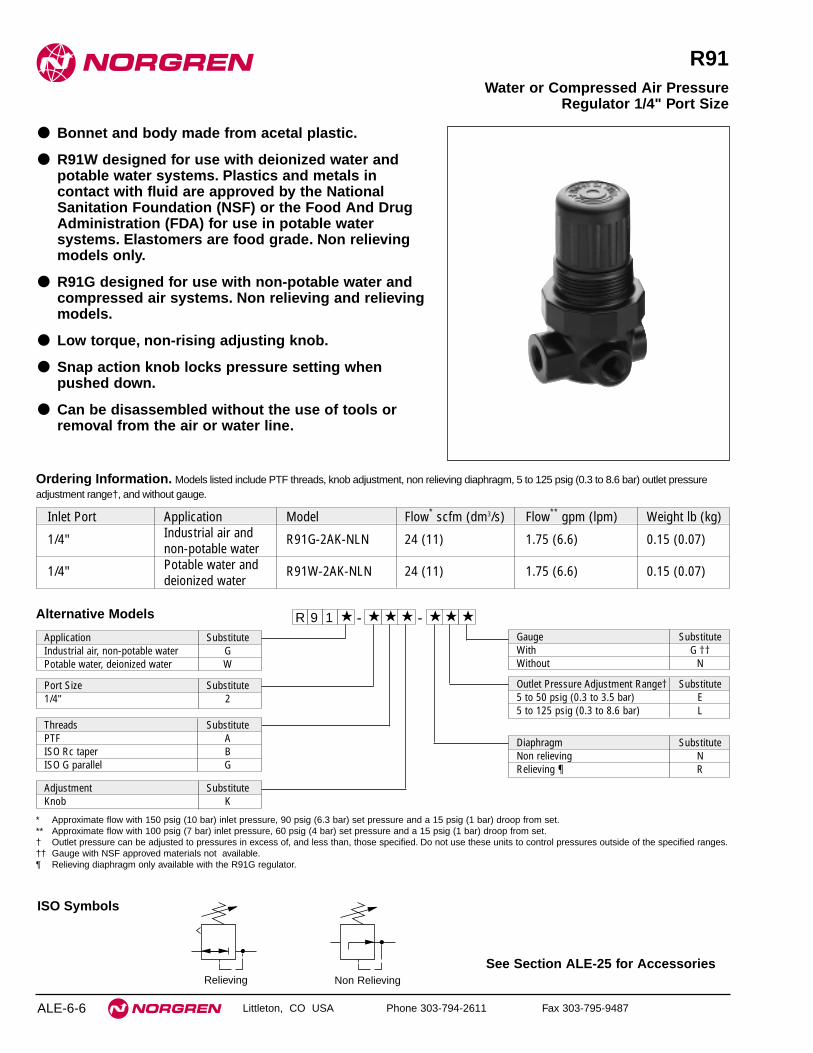
See Section ALE-25 for Accessories
ALE-6-6 Littleton, CO USA Phone 303-794-2611 Fax 303-795-9487
R91
● Bonnet and body made from acetal plastic.
● R91W designed for use with deionized water andpotable water systems. Plastics and metals incontact with fluid are approved by the NationalSanitation Foundation (NSF) or the Food And DrugAdministration (FDA) for use in potable watersystems. Elastomers are food grade. Non relievingmodels only.
● R91G designed for use with non-potable water andcompressed air systems. Non relieving and relievingmodels.
● Low torque, non-rising adjusting knob.
● Snap action knob locks pressure setting whenpushed down.
● Can be disassembled without the use of tools orremoval from the air or water line.
Water or Compressed Air PressureRegulator 1/4" Port Size
Non RelievingRelieving
ISO Symbols
R 9 1 -★ ★ ★ - ★★ ★ ★
Port Size Substitute1/4" 2
Threads SubstitutePTF AISO Rc taper BISO G parallel G
Diaphragm SubstituteNon relieving NRelieving ¶ R
Gauge SubstituteWith G ††Without N
Application SubstituteIndustrial air, non-potable water GPotable water, deionized water W
Adjustment SubstituteKnob K
Alternative Models
Outlet Pressure Adjustment Range† Substitute5 to 50 psig (0.3 to 3.5 bar) E5 to 125 psig (0.3 to 8.6 bar) L
* Approximate flow with 150 psig (10 bar) inlet pressure, 90 psig (6.3 bar) set pressure and a 15 psig (1 bar) droop from set.** Approximate flow with 100 psig (7 bar) inlet pressure, 60 psig (4 bar) set pressure and a 15 psig (1 bar) droop from set.† Outlet pressure can be adjusted to pressures in excess of, and less than, those specified. Do not use these units to control pressures outside of the specified ranges.†† Gauge with NSF approved materials not available.¶ Relieving diaphragm only available with the R91G regulator.
Ordering Information. Models listed include PTF threads, knob adjustment, non relieving diaphragm, 5 to 125 psig (0.3 to 8.6 bar) outlet pressureadjustment range†, and without gauge.
Inlet Port Application Model Flow* scfm (dm3/s) Flow** gpm (lpm) Weight lb (kg)
1/4" Industrial air and R91G-2AK-NLN 24 (11) 1.75 (6.6) 0.15 (0.07)non-potable water
1/4" Potable water and R91W-2AK-NLN 24 (11) 1.75 (6.6) 0.15 (0.07)deionized water

ALE-6-7Littleton, CO USA Phone 303-794-2611 Fax 303-795-9487
R91 Special Purpose Regulators
Technical DataFluid
R91G: Compressed air and non-potable waterR91W: Potable water, deionized water
Maximum pressure: 150 psig (10 bar)Operating temperature
Water service: 35° to 125°F (2° to 52°C) Air service: 0° to 125°F (-20° to 52°C) *
* When used in air service, air supply must be dry enough to avoid ice formation at temperaturesbelow 35°F (2°C).
Typical flow for compressed air service at 150 psig (10 bar) inlet pressure, 90 psig(6.3 bar) set pressure and a droop of 15 psig (1 bar) from set: 24 scfm (11 dm3/s).
Typical flow for water service at 100 psig (7 bar) inlet pressure, 60 psig (4 bar) setpressure and a droop of 15 psig (1 bar) from set: 1.75 US gpm per minute (6.6 liters)
Gauge ports:1/8 PTF with PTF main portsR1/8 with ISO Rc main portsR1/8 with ISO G main ports
MaterialsBody and bonnet: AcetalValve
R91G: Brass/nitrileR91W: Stainless steel/food grade EPDM
Valve seat: AcetalValve seat o-ring
R91G: NitrileR91W: Food grade EPDM
DiaphragmR91G: Acetal/nylon inserted nitrileR91W: Acetal/nylon inserted nitrile, food grade
Gauge port plugs: Polypropylene (furnished only with PTF-ported units)
Typical Performance Characteristics
PORT SIZE 1/4" SPRING RANGE: 5 to 50 psig (0.3 to 3.5 bar)INLET PRESSURE: 100 psig (7 bar)
WATER FLOW CHARACTERISTICS
0 2 4 6 8 10 liters/min
WATER FLOW
0 0.5 1.0 1.5 2.0 2.5 US gal./min
OU
TL
ET
PR
ES
SU
RE
4
3
2
1
0
bar
50
40
30
20
10
0
psi
g
PORT SIZE: 1/4"SPRING RANGE: 5 to 125 psig (0.3 to 8.6 bar)INLET PRESSURE: 150 psig (10 bar)
AIR FLOW CHARACTERISTICS
0 5 10 15 20 25 dm3/s
AIR FLOW
0 10 20 30 40 50 scfm
OU
TL
ET
PR
ES
SU
RE
100
80
60
40
20
0
psi
g
8
6
4
2
0
bar
2.13
(54
) 1.50
(38
)
1.63 (41)
1.50 (38)
0.9
(25) 2.
54 (
65)
3.01
(76
)
1.1 (28)
0.73(19)
0.90(23)
Panel mounting hole diameter 1.19" (30 mm)Maximum panel thickness 0.25" (6 mm)
Service KitsItem Type Part numberService kit R91W, non relieving 3407-93
R91G, non relieving 3407-94R91G, relieving 3407-95
Service kit contains slip ring, diaphragm, valve seat with o-ring,valve, and valve spring.
All Dimensions in Inches (mm)
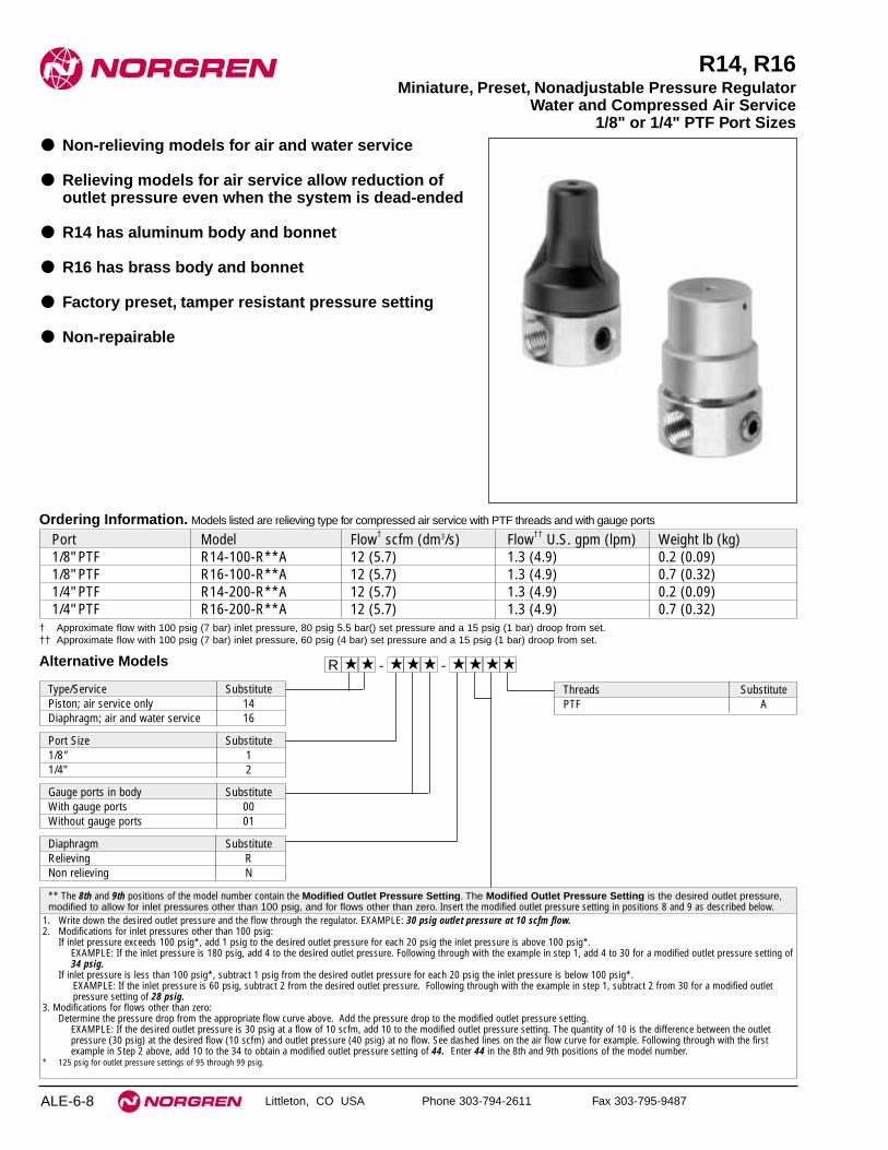
ALE-6-8 Littleton, CO USA Phone 303-794-2611 Fax 303-795-9487
R14, R16
● Non-relieving models for air and water service
● Relieving models for air service allow reduction ofoutlet pressure even when the system is dead-ended
● R14 has aluminum body and bonnet
● R16 has brass body and bonnet
● Factory preset, tamper resistant pressure setting
● Non-repairable
Miniature, Preset, Nonadjustable Pressure Regulator Water and Compressed Air Service
1/8" or 1/4" PTF Port Sizes
Alternative Models ★R ★ ★ ★ ★ ★★ -★ ★ -
Port Size Substitute1/8" 11/4" 2
Threads SubstitutePTF A
** The 8th and 9th positions of the model number contain the Modified Outlet Pressure Setting. The Modified Outlet Pressure Setting is the desired outlet pressure,modified to allow for inlet pressures other than 100 psig, and for flows other than zero. Insert the modified outlet pressure setting in positions 8 and 9 as described below.
1. Write down the desired outlet pressure and the flow through the regulator. EXAMPLE: 30 psig outlet pressure at 10 scfm flow.2. Modifications for inlet pressures other than 100 psig:
If inlet pressure exceeds 100 psig*, add 1 psig to the desired outlet pressure for each 20 psig the inlet pressure is above 100 psig*.EXAMPLE: If the inlet pressure is 180 psig, add 4 to the desired outlet pressure. Following through with the example in step 1, add 4 to 30 for a modified outlet pressure setting of34 psig.
If inlet pressure is less than 100 psig*, subtract 1 psig from the desired outlet pressure for each 20 psig the inlet pressure is below 100 psig*.EXAMPLE: If the inlet pressure is 60 psig, subtract 2 from the desired outlet pressure. Following through with the example in step 1, subtract 2 from 30 for a modified outletpressure setting of 28 psig.
3. Modifications for flows other than zero:Determine the pressure drop from the appropriate flow curve above. Add the pressure drop to the modified outlet pressure setting.
EXAMPLE: If the desired outlet pressure is 30 psig at a flow of 10 scfm, add 10 to the modified outlet pressure setting. The quantity of 10 is the difference between the outletpressure (30 psig) at the desired flow (10 scfm) and outlet pressure (40 psig) at no flow. See dashed lines on the air flow curve for example. Following through with the firstexample in Step 2 above, add 10 to the 34 to obtain a modified outlet pressure setting of 44. Enter 44 in the 8th and 9th positions of the model number.
* 125 psig for outlet pressure settings of 95 through 99 psig.
Diaphragm SubstituteRelieving RNon relieving N
Gauge ports in body SubstituteWith gauge ports 00Without gauge ports 01
Ordering Information. Models listed are relieving type for compressed air service with PTF threads and with gauge ports
Port Model Flow† scfm (dm3/s) Flow†† U.S. gpm (lpm) Weight lb (kg)1/8" PTF R14-100-R**A 12 (5.7) 1.3 (4.9) 0.2 (0.09)1/8" PTF R16-100-R**A 12 (5.7) 1.3 (4.9) 0.7 (0.32)1/4" PTF R14-200-R**A 12 (5.7) 1.3 (4.9) 0.2 (0.09)1/4" PTF R16-200-R**A 12 (5.7) 1.3 (4.9) 0.7 (0.32)
† Approximate flow with 100 psig (7 bar) inlet pressure, 80 psig 5.5 bar() set pressure and a 15 psig (1 bar) droop from set.†† Approximate flow with 100 psig (7 bar) inlet pressure, 60 psig (4 bar) set pressure and a 15 psig (1 bar) droop from set.
Type/Service SubstitutePiston; air service only 14Diaphragm; air and water service 16

See Section ALE-25 for Accessories
R14 and R16 Special Purpose Regulators
ALE-6-9
All Dimensions in Inches (mm)
Littleton, CO USA Phone 303-794-2611 Fax 303-795-9487
Technical DataFluid
R14: Compressed airR16: Water and compressed air
Maximum pressure: 400 psig (27 bar)Operating temperature
Water service: 35° to 175°F (2° to 79°C)Air service: -30° to 175°F (-34° to 79°C) *
* Air supply must be dry enough to avoid ice formation at temperatures below 35°F (2°C).Type
R14: Piston, relieving or non-relievingR16: Diaphragm. relieving or non-relieving
Typical flow for water service at 100 psig (7 bar) inlet pressure, 60 psig (4 bar) setpressure and a droop of 15 psig (1 bar) from set: 1.3 U.S. gpm (4.9 liters perminute)
Typical flow for compressed air service at 100 psig (7 bar) inlet pressure, 80 psig(5.5 bar) set pressure and a droop of 15 psig (1 bar) from set: 12 scfm (5.7dm3/s)
Gauge ports: 1/8" PTFFactory preset outlet pressure settings: 0,2 to 6,8 bar (3 to 99 psig)Outlet pressure tolerance:
Outlet pressure setting - psig (bar) Tolerance - psig (bar) **3 to 20 psig (0.21 to 1.38 bar) ± 1.0 psig (0.07 bar)21 to 50 psig (1.45 to 3.45 bar) ± 2.0 psig (0.14 bar)51 to 99 psig (3.52 to 6.84 bar) ± 3.0 psig (0.21 bar)
** When outlet pressure is preset at the factory, the following conditions existFlow thru regulator: No flowInlet pressure:
100 psig (6.9 bar) for outlet pressures up through 95 psig (6.6 bar)125 psig (8.6 bar) for outlet pressures of 96 through 99 psig (6.7 through 6.8 bar)
MaterialsBody and bonnet
R14: AluminumR16: Brass
Valve: BrassValve seat: Acetal resinElastomers: Nitrile
ISO Symbols
Relieving Non relieving
PORT SIZE 1/8", 1/4" INLET PRESSURE: 100 psig (7 bar)
WATER FLOW CHARACTERISTICS
0 2 4 6 8 10 litres/min
WATER FLOW
0 0.5 1.0 1.5 2.0 2.5 US gal./min
OU
TL
ET
PR
ES
SU
RE
8
6
4
2
0
bar
100
80
60
40
20
0
psi
g
PORT SIZE: 1/8", 1/4"INLET PRESSURE: 100 psig (7 bar)
AIR FLOW CHARACTERISTICS
0 2 4 6 8 10 dm3/s
AIR FLOW
OU
TL
ET
PR
ES
SU
RE
8
6
4
2
0
bar
10 psig Difference
100
80
60
40
20
0
psi
g
30
0 4 8 12 16 20 scfm10
Typical Performance Characteristics
R14
2.58
(65
)
0.40
(10
)
1.48 (38)
1.48
(38
)
2.28
(58
)
0.40
(10
)
1.48 (38)
1.48
(38
)
R16

See Section ALE-25 for Accessories
ALE-6-10 Littleton, CO USA Phone 303-794-2611 Fax 303-795-9487
R43
● Non-relieving models
● Brass body, corrosion resistant construction
● Balanced valve minimizes effects of inlet pressurevariations on outlet pressure
● T-bar adjustment standard, nonrising knobadjustment optional
● Full flow gauge ports can be used as auxiliary outlets
● Panel mounting nut standard
● Can be disassembled without the use of tools orremoval from the air or water line.
Water and Compressed Air Service Pressure Regulator 1/4", 3/8" and 1/2" Port Sizes
ISO Symbols
Non relieving
Alternative Models 4R 3 ★ ★ ★ ★★ -★ ★ -
Port Size Substitute1/4" 23/8" 31/2" 4
Outlet Pressure Adjustment Range* Substitute5 to 50 psig (0.3 to 3.5 bar) E5 to 125 psig (0.3 to 8.6 bar) L15 to 250 psig (1 to 17 bar) S
Gauges SubstituteWith GWithout N
Diaphragm SubstituteNon relieving N
Adjustment SubstituteKnob 00T-handle with 1/4" and 3/8" ports 01T-handle with 1/2" ports 06
Ordering Information. Models listed have T-handle adjustment, 5 to 125 psig (0.3 to 8.5 bar) outlet pressure adjustment range*, and PTFthreads. A gauge is not included.
Port Model Flow† U.S. gpm (lpm) Weight lb (kg)1/4" R43-201-NNLA 6 (23) 2.4 (1.09)3/8" R43-301-NNLA 6 (23) 2.4 (1.09)1/2" R43-406-NNLA 9 (34) 2.4 (1.09)
Threads SubstitutePTF AISO Rc taper BISO G parallel G
* Outlet pressure can be adjusted to pressures in excess of, and less than, thosespecified. Do not use these units to control pressures outside of the specifiedranges.
† Typical flow with 150 psig (10 bar) inlet pressure, 90 psig (6.3 bar) set pressureand 15 psig (1 bar) droop from set.
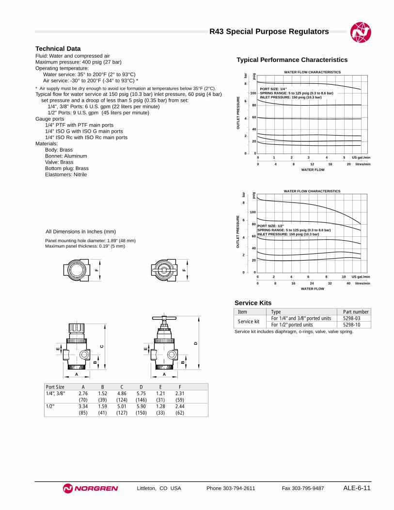
R43 Special Purpose Regulators
ALE-6-11
All Dimensions in Inches (mm)
Littleton, CO USA Phone 303-794-2611 Fax 303-795-9487
Technical DataFluid: Water and compressed airMaximum pressure: 400 psig (27 bar)Operating temperature:
Water service: 35° to 200°F (2° to 93°C)Air service: -30° to 200°F (-34° to 93°C) *
* Air supply must be dry enough to avoid ice formation at temperatures below 35°F (2°C).Typical flow for water service at 150 psig (10.3 bar) inlet pressure, 60 psig (4 bar)
set pressure and a droop of less than 5 psig (0.35 bar) from set:1/4", 3/8" Ports: 6 U.S. gpm (22 liters per minute)1/2" Ports: 9 U.S. gpm (45 liters per minute)
Gauge ports1/4" PTF with PTF main ports1/4" ISO G with ISO G main ports1/4" ISO Rc with ISO Rc main ports
Materials:Body: BrassBonnet: AluminumValve: BrassBottom plug: BrassElastomers: Nitrile
PORT SIZE: 1/2" SPRING RANGE: 5 to 125 psig (0.3 to 8.6 bar)INLET PRESSURE: 150 psig (10.3 bar)
WATER FLOW CHARACTERISTICS
0 8 16 24 32 40 litres/min
WATER FLOW
0 2 4 6 8 10 US gal./min
OU
TL
ET
PR
ES
SU
RE
8
6
4
2
0
bar
100
80
60
40
20
0
psi
g
PORT SIZE: 1/4" SPRING RANGE: 5 to 125 psig (0.3 to 8.6 bar)INLET PRESSURE: 150 psig (10.3 bar)
WATER FLOW CHARACTERISTICS
0 4 8 12 16 20 litres/min
WATER FLOW
0 1 2 3 4 5 US gal./min
OU
TL
ET
PR
ES
SU
RE
8
6
4
2
0
bar
100
80
60
40
20
0
psi
g
Typical Performance Characteristics
A
B
CE
F F
A
B
D
E
Panel mounting hole diameter: 1.89" (48 mm)Maximum panel thickness: 0.19" (5 mm)
Port Size A B C D E F1/4", 3/8" 2.76 1.52 4.86 5.75 1.21 2.31
(70) (39) (124) (146) (31) (59)1/2" 3.34 1.59 5.01 5.90 1.28 2.44
(85) (41) (127) (150) (33) (62)
Service KitsItem Type Part number
Service kitFor 1/4" and 3/8" ported units 5298-03For 1/2" ported units 5298-10
Service kit includes diaphragm, o-rings, valve, valve spring.
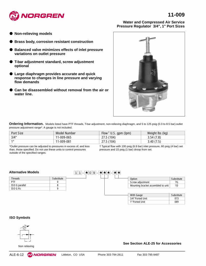
See Section ALE-25 for Accessories
ALE-6-12 Littleton, CO USA Phone 303-794-2611 Fax 303-795-9487
11-009
● Non-relieving models
● Brass body, corrosion resistant construction
● Balanced valve minimizes effects of inlet pressurevariations on outlet pressure
● T-bar adjustment standard, screw adjustmentoptional
● Large diaphragm provides accurate and quickresponse to changes in line pressure and varyingflow demands
● Can be disassembled without removal from the air orwater line.
Water and Compressed Air ServicePressure Regulator 3/4", 1" Port Sizes
ISO Symbols
Non relieving
Alternative Models
Port Size Model Number Flow † U.S. gpm (lpm) Weight lbs (kg)3/4" 11-009-065 27.5 (104) 3.54 (7.8)1" 11-009-081 27.5 (104) 3.40 (7.5)
Ordering Information. Models listed have PTF threads, T-bar adjustment, non-relieving diaphragm, and 5 to 125 psig (0.3 to 8.5 bar) outletpressure adjustment range*. A gauge is not included.
Threads SubstitutePTF 0ISO G parallel 8ISO G Rc 9
0★- ★ ★ ★★ ★9 - -11
Option SubstituteScrew adjustment 7GMounting bracket assembled to unit 1D
*Outlet pressure can be adjusted to pressures in excess of, and less than, those specified. Do not use these units to control pressuresoutside of the specified ranges.
† Typical flow with 100 psig (6.9 bar) inlet pressure, 60 psig (4 bar) setpressure and 15 psig (1 bar) droop from set.
With Gauge Substitute3/4" Ported Unit 0731" Ported Unit 089

11-009 Special Purpose Regulators
ALE-6-13
All Dimensions in Inches (mm)
Littleton, CO USA Phone 303-794-2611 Fax 303-795-9487
Technical DataFluid: Water and compressed airMaximum pressure: 400 psig (28 bar)Operating temperature
Water service: 35° to 200°F (2° to 93°C)Air service: -30° to 200°F (-34° to 93°C) *
* Air supply must be dry enough to avoid ice formation at temperatures below 35°F (2°C).Typical flow at 100 psig (6.9 bar) inlet pressure, 60 psig (4 bar) set pressure and a
15 psig (1 bar) droop from set:27.5 U.S. gpm (104 liters per minute)
Gauge ports:1/8" PTF with PTF main portsG1/8 with ISO G main portsRc1/4 with ISO Rc main ports
MaterialsBody: BrassBonnet: Aluminum and steelValve: BrassBottom plug: BrassElastomers: Nitrile
Typical Performance Characteristics
PORT SIZE: 3/4", 1" SPRING RANGE: 5 to 125 psig (0.3 to 8.5 bar)INLET PRESSURE: 100 psig (6.9 bar)
WATER FLOW CHARACTERISTICS
0 20 40 60 80 100 lpm
WATER FLOW
0 5 10 15 20 25 30 gpm
OU
TL
ET
PR
ES
SU
RE
8
6
4
2
0
bar
100
80
60
40
20
0
psi
g
9.50
(24
1)
5.00 (127)
1.62
(41
)
Service KitsType Part numberNon-relieving 2436-03
Service kit includes diaphragm, valve seat, valve pin, valve pingasket, valve, valve spring, and o-rings.

See Section ALE-25 for Accessories
ALE-6-14 Littleton, CO USA Phone 303-794-2611 Fax 303-795-9487
11-002
● Large diaphragm provides accurate and quickresponse to changing flow demands and linepressure
● Floating valve pin provides positive valve seating
● Balanced valve minimizes effect of variations in inletpressure on outlet pressure
● Standard relieving models allow reduction ofdownstream pressure when the system is dead-ended
Pressure Regulator1/4", 3/8", 1/2" Port Sizes
Port Size Model Number Flow† scfm (dm3/s) Weight lbs (kg)1/4" 11-002-013 110 (52) 1.9 (0.86)3/8" 11-002-037 110 (52) 1.9 (0.86)1/2" 11-002-061 260 (123) 2.0 (0.91)
Ordering Information. Models listed have PTF threads, T-bar adjustment, relieving diaphragm, and 5 to 125 psig (0.3 to 8.5 bar) outletpressure adjustment range*.
† Typical flow with 150 psig (10 bar) inlet pressure, 90 psig (6.3 bar) set pressure and 15 psig (1 bar) droop from set.*Outlet pressure can be adjusted to pressures in excess of, and less than, those specified. Do not use these units to control pressures outside of the specified ranges.
Alternative Models
Threads SubstitutePTF 0ISO G parallel 8ISO G Rc 9
0★- ★ ★ ★★ ★2 - -11
Option SubstituteHandwheel adjustment 8CScrew adjustment 8BMounting bracket assembled to unit 1AThreaded bonnet for panel mounting, hand wheel adjustment 2AThreaded bonnet for panel mounting, T-bar adjustment 2BThreaded bonnet for panel mounting, screw adjustment 2C
Outlet Pressure Adjustment Range*5 to 50 psig (0.3 to 3.5 bar)
Port Size Relief Type Gauge Substitute1/4" Non-relieving Without 0031/4" Relieving Without 0153/8" Non-relieving Without 0273/8" Relieving Without 0391/2" Non-relieving Without 0511/2" Relieving Without 0631/4" Non-relieving With 0091/4" Relieving With 0213/8" Non-relieving With 0333/8" Relieving With 0451/2" Non-relieving With 0571/2" Relieving With 069
Outlet Pressure Adjustment Range*5 to 125 psig (0.3 to 8.5 bar)
Port Size Relief Type Gauge Substitute1/4" Non-relieving Without 0011/4" Relieving Without 0133/8" Non-relieving Without 0253/8" Relieving Without 0371/2" Non-relieving Without 0491/2" Relieving Without 0611/4" Non-relieving With 0071/4" Relieving With 0193/8" Non-relieving With 0313/8" Relieving With 0431/2" Non-relieving With 0551/2" Relieving With 067
Outlet Pressure Adjustment Range*5 to 250 psig (0.3 to 17 bar)
Port Size Relief Type Gauge Substitute1/4" Non-relieving Without 0051/4" Relieving Without 0173/8" Non-relieving Without 0293/8" Relieving Without 0411/2" Non-relieving Without 0531/2" Relieving Without 0651/4" Non-relieving With 0111/4" Relieving With 0233/8" Non-relieving With 0353/8" Relieving With 0471/2" Non-relieving With 0591/2" Relieving With 071
* Outlet pressure can be adjusted to pressures in excess of, and less than, those specified. Do not use these units to control pressures outside of the specified ranges.

ALE-6-15
All Dimensions in Inches (mm)
Littleton, CO USA Phone 303-794-2611 Fax 303-795-9487
11-002 Special Purpose Regulators
Technical DataFluid: Compressed airMaximum pressure: 400 psig (28 bar)Operating temperature*: -30° to 175°F (-34° to 80°C)*Air supply must be dry enough to avoid ice formation at temperatures below 35°F (2°C)Typical flow with 150 psig (10 bar) inlet pressure, 90 psig (6.3 bar) set pressureand 15 psig (1 bar) droop from from set:
1/4" and 3/8" ports: 110 scfm (52 dm3/s)1/2" ports: 260 scfm (123 dm3/s)
Gauge ports1/8" PTF with PTF main portsRc1/8 with ISO G and ISO Rc main ports
MaterialsBody: ZincBonnet: AluminumValve: Brass and nitrileValve seat: BrassElastomers: NitrileBottom plug
1/4" and 3/8" Ports: Brass1/2" Ports: Nylon
Typical Performance Characteristics
PORT SIZE: 1/4"INLET PRESSURE: 150 psig (10 bar)RANGE: 5 to 125 psig (0.3 to 8.6 bar)
FLOW CHARACTERISTICS
0 5 10 15 20 30 dm3/sAIR FLOW
0 10 20 30 40 50 scfm
OU
TL
ET
PR
ES
SU
RE
8
6
4
2
0
bar
100
80
60
40
20
0
psi
g
120
PORT SIZE: 1/2"INLET PRESSURE: 150 psig (10 bar)RANGE: 5 to 125 psig (0.3 to 8.6 bar)
FLOW CHARACTERISTICS
0 20 40 60 80 100 dm3/sAIR FLOW
0 40 80 120 160 200 scfm
OU
TL
ET
PR
ES
SU
RE
8
6
4
2
0 b
ar
100
80
60
40
20
0
psi
g
120
PORT SIZE: 1/4"INLET PRESSURE: 100 psig (7 bar)RANGE: 5 to 125 psig (0.3 to 8.6 bar)
FLOW CHARACTERISTICS
0 5 10 15 20 30 dm3/s
AIR FLOW
0 10 20 30 40 50 scfm
OU
TL
ET
PR
ES
SU
RE
8
6
4
2
0
bar
100
80
60
40
20
0
psi
g
120
PORT SIZE: 1/2"INLET PRESSURE: 100 psig (7 bar)RANGE: 5 to 125 psig (0.3 to 8.6 bar)
FLOW CHARACTERISTICS
0 20 40 60 80 100 dm3/sAIR FLOW
0 40 80 120 160 200 scfm
OU
TL
ET
PR
ES
SU
RE
8
6
4
2
0
bar
100
80
60
40
20
0
psi
g
120
Service KitsType Part numberRelieving, 1/4" and 3/8" ports 529-03Relieving, 1/2" ports 535-03Non-relieving, 1/4" and 3/8" ports 529-01Non-relieving, 1/2" ports 535-01
Service kit includes diaphragm, valve, valve spring, and o-rings.
* Regulators with 1/4" and 3/8" ports.** Regulators with 1/2" ports.
3.13 (80) *3.38 (86) **
3.00
(76
) *
3.31
(84
) **
6.41
(16
3) *
6.50
(16
5) *
*
Panel Mounting OptionRequires alternative threaded bonnet.Panel mounting hole diameter: 1.06" (27 mm).Panel thickness: 0.2" to 0.4" (5 to 10 mm).
2.00 (50)
1.25
(32
) *
1.44
(37
) **
7.29
(18
5) *
7.38
(18
7) *
*
3.06
(78
) *
3.13
(80
) **
1.63
(41
)
ISO SymbolsRelieving Non relieving

See Section ALE-25 for Accessories
ALE-6-16 Littleton, CO USA Phone 303-794-2611 Fax 303-795-9487
R24
● High flow regulator with exceptional high relief flow
● Adjusting knob can be set in the field to stop at somemaximum pressure setting or some minimumpressure setting
● Easy to adjust even at high output pressures
● Balanced valve minimizes effect of variations in inletpressure on outlet pressure
● Constant bleed feature provides maximum sensitivityto system changes
● Relieving feature allows reduction of downstreampressure when the system is dead-ended
● Full flow gauge ports
Micro Trol Pressure Regulator1/4" to 1-1/4" Port Sizes
ISO Symbol
Relieving
Alternative Models
Port Size Substitute1/4" 23/8" 31/2" 43/4" 61" 81-1/4" A
Option SubstituteNot applicable 0
Type SubstituteKnob adjusting 0
Threads SubstitutePTF AISO Rc taper BISO G parallel G
Port Size Model Weight lb (kg)1⁄4" R24-200-RGLA 1.90 (0.86)3⁄8" R24-300-RGLA 1.83 (0.83)1⁄2" R24-400-RGLA 1.79 (0.81)3⁄4" R24-600-RGLA 2.73 (1.24)1" R24-800-RGLA 2.73 (1.24)1-1⁄4" R24-A00-RGLA 2.65 (1.20)
Ordering Information. Models listed are constant bleed units with relieving diaphragm, 10 to 125 psig (0.7 to 8 bar) outlet pressure
adjustment range, and PTF threads.
Outlet Pressure Adjustment Ranges* Substitute5 to 30 psig (0.3 to 2 bar) C5 to 60 psig (0.3 to 4 bar) F10 to 125 psig (0.7 to 8 bar) L10 to 250 psig (0.7 to 17 bar) S
Gauge SubstituteWith G**Without N
Diaphragm SubstituteRelieving R
2R 4 - ★ ★ ★ ★ ★ ★ ★
* Outlet pressure can be adjusted to pressures in excess of, and less than, those specified.Do not use these units to control pressures outside of the specified ranges.
** A factory installed gauge is only available with PTF threads (A in last positionof model number). If a gauge is desired with ISO threads (B or G in lastposition), order the desired gauge and appropriate reducing bushing fromAccessories.
-

ALE-6-17
All Dimensions in Inches (mm)
R24 Special Purpose Regulators
Littleton, CO USA Phone 303-794-2611 Fax 303-795-9487
Technical DataFluid: Compressed airMaximum inlet pressure: 300 psig (20 bar) Operating temperature: 0° to 150°F (-20° to 80°C)*
* Air supply must be dry enough to avoid ice formation at temperatures below 35°F (2°C).Typical flow with 150 psig (10 bar) inlet pressure, 90 psig (6.3 bar) set pressure
and 15 psig (1 bar) droop from from set1/2" ports: 200 scfm (94 dm3/s)1-1/4" ports: 700 scfm (330 dm3/s)
Maximum bleed rate at 50 psig (3.5 bar) outlet pressure: 0.031 scfm (0.016 dm3/s) †† Maximum bleed rate occurs under dead-end (no flow) conditions.Port sizes:
Main Gauge1/4" 1/4"3/8" 3/8"1/2", 3/4", 1", 1-1/4" 1/2"
Thread type: PTF, ISO G, or RcMaterials
Body, top cap: ZincMain valve, adjusting screw: BrassPilot valve, relief valve: AcetalElastomers: NitrileBottom Plug: Acetal
Typical Performance CharacteristicsRANGE: 10 to 232 psi (0.7 to 16 bar)
FLOW CHARACTERISTICS
0 20 40 60 80 100 dm3/s
AIR FLOW
0 40 80 120 160 200 240 scfm
8
6
4
2
0
OU
TL
ET
PR
ES
SU
RE
bar
g
psi
g
PORT SIZE: 1/2"INLET PRESSURE: 150 psig (10 bar)RANGE: 10 to 125 psig (0.7 to 8.6 bar)
100
80
60
40
20
0
120
FLOW CHARACTERISTICS
0 50 100 150 200 250 300 dm3/s
AIR FLOW
0 100 200 300 400 500 600 700 scfm
8
6
4
2
0
bar
g
100
80
60
40
20
0
psi
g
PORT SIZE: 1-1/4"INLET PRESSURE: 150 psig (10 bar)RANGE: 10 to 125 psig (0.7 to 8.6 bar)
RELIEF FLOW CHARACTERISTICS
0 10 20 30 40 50 dm3/s
AIR FLOW
0 20 40 60 80 100 120 scfm
OU
TL
ET
PR
ES
SU
RE
8
6
4
2
0
bar
g
100
80
60
40
20
0
psi
g
TYPICAL ALL MODELSINLET PRESSURE: 200 psig (14 bar g)
3.50
(90
)
5.37
(13
6)
3.65 (93)
2.72
(69
)
3.43
(87
)
4.41
(11
2)
2.72
(69
)
2.09 (53)
Service KitsItem Type Part numberService kit 1⁄4, 3⁄8, 1⁄2 5292-52 Service kit 3⁄4, 1, 1-1⁄4 5292-53
Service kits include seals, main valve and spring.
Panel mounting hole diameter: 1.26" (32 mm)Maximum panel thickness: 0 to 0.12" (3 mm)


Littleton, CO USA Phone 303-794-2611 Fax 303-795-9487 ALE-7-1
Section 7
ContentsR30M Manifold Regulator 8mm and 10mm ports . . . . . . . . . . . . . .ALE-7-2R72M Manifold Regulator 1/4" and 3/8" ports . . . . . . . . . . . . . . . . .ALE-7-4
Manifold Regulators8mm, 10mm, 1/4" and 3/8" portsizes.
R30M R72M
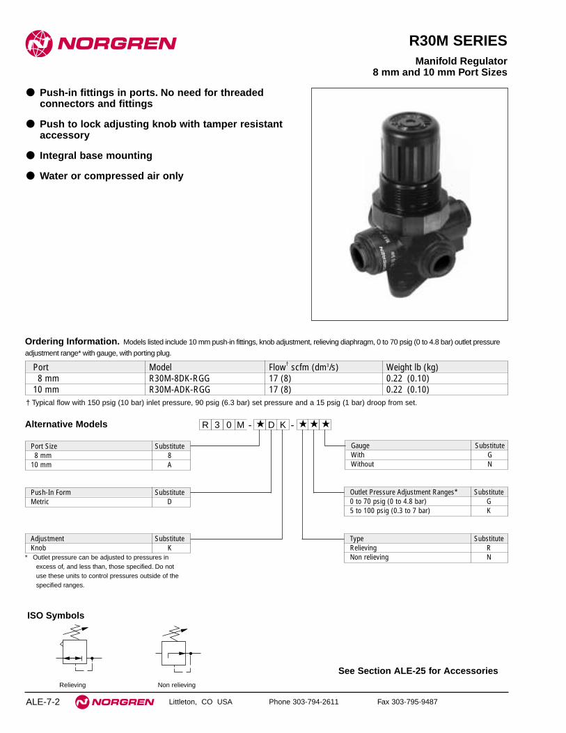
See Section ALE-25 for Accessories
ALE-7-2 Littleton, CO USA Phone 303-794-2611 Fax 303-795-9487
R30M SERIES
● Push-in fittings in ports. No need for threadedconnectors and fittings
● Push to lock adjusting knob with tamper resistantaccessory
● Integral base mounting
● Water or compressed air only
Manifold Regulator8 mm and 10 mm Port Sizes
ISO Symbols
Relieving Non relieving
Ordering Information. Models listed include 10 mm push-in fittings, knob adjustment, relieving diaphragm, 0 to 70 psig (0 to 4.8 bar) outlet pressure
adjustment range* with gauge, with porting plug.
† Typical flow with 150 psig (10 bar) inlet pressure, 90 psig (6.3 bar) set pressure and a 15 psig (1 bar) droop from set.
Port Model Flow† scfm (dm3/s) Weight lb (kg)8 mm R30M-8DK-RGG 17 (8) 0.22 (0.10)
10 mm R30M-ADK-RGG 17 (8) 0.22 (0.10)
03R M - ★ D - ★K ★ ★
* Outlet pressure can be adjusted to pressures inexcess of, and less than, those specified. Do notuse these units to control pressures outside of thespecified ranges.
Alternative Models
Gauge SubstituteWith GWithout N
Port Size Substitute8 mm 8
10 mm A
Outlet Pressure Adjustment Ranges* Substitute0 to 70 psig (0 to 4.8 bar) G5 to 100 psig (0.3 to 7 bar) K
Push-In Form SubstituteMetric D
Type SubstituteRelieving RNon relieving N
Adjustment SubstituteKnob K
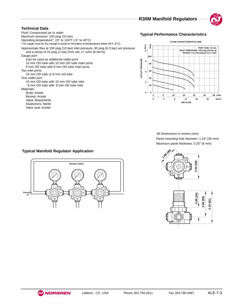
ALE-7-3
All Dimensions in Inches (mm)
R30M Manifold Regulators
Littleton, CO USA Phone 303-794-2611 Fax 303-795-9487
Technical DataFluid: Compressed air or waterMaximum pressure: 150 psig (10 bar)Operating temperature*: 23° to 104°F (-5° to 40°C)* Air supply must be dry enough to avoid ice formation at temperatures below 35°F (2°C).
Approximate flow at 150 psig (10 bar) inlet pressure, 90 psig (6.3 bar) set pressureand a droop of 15 psig (1 bar) from set: 17 scfm (8 dm3/s)
Gauge port:(can be used as additional outlet port)10 mm OD tube with 10 mm OD tube main ports8 mm OD tube with 8 mm OD tube main ports
Two inlet ports:10 mm OD tube or 8 mm o/d tube
One outlet port:10 mm OD tube with 10 mm OD tube inlet8 mm OD tube with 8 mm OD tube inlet
Materials:Body: AcetalBonnet: AcetalValve: Brass/nitrileElastomers: NitrileValve seat: Acetal
FLOW CHARACTERISTICS (AIR)
0 4 8 12 16 20 dm3/s
AIR FLOW
0 8 16 24 32 40 48 scfm
OU
TL
ET
PR
ES
SU
RE
8
6
4
2
0
bar
g
100
80
60
40
20
0
psi
g
PORT SIZE: 10 mmINLET PRESSURE: 150 psig (10 bar g)
RANGE: 5 to 100 psig (0.3 to 7 bar)
Typical Performance Characteristics
2.52
(64
)
1.89 (
48)
0.95
(24
)
2.56
(65
)
3.19
(81
)
Panel mounting hole diameter: 1.19" (30 mm)
Maximum panel thickness: 0.25" (6 mm)
Typical Manifold Regulator Application
Pressure in
Booster signal

See Section ALE-25 for Accessories
ALE-7-4 Littleton, CO USA Phone 303-794-2611 Fax 303-795-9487
R72M
● Excelon design allows in-line or modular installation
● Manifold typically up to six regulators withoutbooster signal
● Balanced valve design for optimum pressure control
● Push to lock adjusting knob with tamper resistantaccessory
● Modular installations with Excelon 72, 73, and 74series can be made to suit particular applications
Excelon 72 Manifold Regulator1/4", 3/8" Port Sizes
ISO Symbols
Relieving Non Relieving
Ordering Information. Models listed include PTF threads, knob adjustment, relieving diaphragm, 5 to 150 psig (0.3 to 10 bar) outlet pressure
adjustment range* with gauge.
† Typical flow with 150 psig (10 bar) inlet pressure, 90 psig (6.3 bar) set pressure and a 15 psig (1 bar) droop from set.
Inlet Port (2) Outlet Port (1) Model Flow† scfm (dm3/s) Weight lb (kg)1/4" 1/4" R72M-2AK-RMG 83 (39) 0.79 (0.36)3/8" 1/4" R72M-3AK-RMG 83 (39) 0.79 (0.36)
R 7 2 -★ ★ ★ - ★★ ★ ★
Inlet Port Size Substitute1/4" 23/8" 3
Threads SubstitutePTF AISO Rc taper BISO G parallel G
Diaphragm SubstituteRelieving RNon relieving N
Gauge SubstituteWith GWithout N
* Outlet pressure can be adjusted topressures in excess of, and less than, thosespecified. Do not use these units to controlpressures outside of the specified ranges.
Adjustment SubstituteKnob KT-bar T
Alternative Models
Outlet Pressure Adjustment Range* Substitute5 to 30 psig (0.3 to 2 bar) C5 to 60 psig (0.3 to 4 bar) F5 to 150 psig (0.3 to 10 bar) M
Type SubstituteManifold M

ALE-7-5
All Dimensions in Inches (mm)
R72M Manifold Regulators
Littleton, CO USA Phone 303-794-2611 Fax 303-795-9487
Technical DataFluid: Compressed airMaximum pressure: 290 psig (20 bar)Operating temperature*: -30° to 150°F (-34° to 65°C)* Air supply must be dry enough to avoid ice formation at temperatures below 35°F (2°C).
Typical flow at 150 psig (10 bar) inlet pressure, 90 psig (6.3 bar) set pressure anda droop of 15 psig (1 bar) from set: 83 scfm (39 dm3/s)
Two inlet ports:1/4" or 3/8" PTF1/4" or 3/8" ISO Rc1/4" or 3/8" ISO G
One outlet port:1/4" PTF with PTF inlet ports1/4" ISO Rc with ISO Rc inlet ports1/4" ISO Rc with ISO G inlet ports
One gauge port:1/8" PTF with PTF inlet ports1/8" ISO Rc with ISO Rc inlet ports1/8" ISO Rc with ISO G inlet ports
MaterialsBody: ZincBonnet: AcetalValve: BrassElastomers: NitrileBottom plug: Acetal
Typical Performance Characteristics
FLOW CHARACTERISTICS
0 10 20 30 40 50 dm3/s
AIR FLOW
0 20 40 60 80 100 120 scfm
OU
TL
ET
PR
ES
SU
RE
8
6
4
2
0
bar
g
100
80
60
40
20
0
psi
g
PORT SIZE: 3/8"INLET PRESSURE: 150 psig (10 bar g)
RANGE: 5 to 150 psig (0.3 to 10 bar)
Typical Manifold Regulator Application
R72M R72M R72M R72M R72M R72MPressure in
Booster signal
1.97 (50) 1.97 (50)
2.48 (63)
1.89
(48
)2.
36 (
60)
2.88
(73
)1.
31 (
33)
4.03
(10
2)1.
31 (
33)
1.01
(26
)
1.01
(26
)
1.89
(48
)2.
36 (
60)
P1 P1 P1 P1
Panel mounting hole diameter: 1.57" (40 mm)Maximum panel thickness: 0.16" (4 mm)
Outlet Pressure
1/4" Outlet Port
1/4" or 3/8" Inlet Port
1/8" Gauge Port
1/4" or 3/8" Inlet Port
Service KitsItem Type Part Number
Service kitRelieving 4381-500Non relieving 4381-501
Service kit includes diaphragm assembly, valve assembly,valve spring and o-rings.


Littleton, CO USA Phone 303-794-2611 Fax 303-795-9487 ALE-8-1
Section 8
Contents11-018 Precision Air Pressure Regulator 1/4" ports . . . . . . . . . . . .ALE-8-2R38 Instrument Regulator Aluminum Model 1/4" ports . . . . . . . . .ALE-8-4
Precision andInstrument Regulators1/4" port size
11-018 R38

See Section ALE-25 for Accessories
ALE-8-2 Littleton, CO USA Phone 303-794-2611 Fax 303-795-9487
11-018
● Fast response
● Minimum overshoot during flow changes
● Precision regulation obtained by pilot valve design -small change in the pilot valve position results in alarge change in the main valve position
● Constant bleed feature provides maximum sensitivityto system changes
● Relieving feature allows reduction of downstreampressure when the system is dead-ended
Precision Air Pressure Regulator1/4" Port Size
ISO Symbols
Relieving
Port Size Outlet Pressure Adjustment Range* Model Number Flow scfm (dm3/s) Weight lbs (kg)1/4" 0.4 to 10 psig (0.03 to 0.69 bar) 11-018-146 12 (5.66)† 1.4 (0.64)1/4" 1.0 to 60 psig (0.1 to 4.1 bar) 11-018-100 12 (5.66)† 1.4 (0.64)1/4" 3 to 150 psig (0.2 to 10.3 bar) 11-018-110 12 (5.66)†† 1.4 (0.64)
Ordering Information. Models listed have PTF threads, hand wheel adjustment, and relieving diaphragm. A gauge is not included.
* Outlet pressure can be adjusted to pressures in excess of, and less than, those specified. Do not use these units to control pressures outside of the specified ranges.† Typical flow with 100 psig (7 bar) inlet pressure, 60 psig (4.1 bar) set pressure and 0.125 psig (0.009 bar) droop from set.†† Typical flow with 200 psig (14 bar) inlet pressure, 60 psig (4.1 bar) set pressure and 0.250 psig (0.017 bar) droop from set.
Alternative Models
Threads SubstitutePTF 0ISO G parallel 8ISO G Rc 9
1★- ★ ★ ★8 -11
Screw Adjustment Substitute-100 with slotted screw adjustment 101-110 with slotted screw adjustment 112
Service KitsType Part numberLow Pressure Models 2787-01High Pressure Models 2787-02Special tool to install main valve seat 681-01
Service kit includes o-rings, seals, pilot diaphragm, pilot spring, maindiaphragm, main valve, main valve seat, diffuser screen, constant bleed orificeand orifice filter

11-018 Precision Air Pressure Regulator
ALE-8-3
All Dimensions in Inches (mm)
Littleton, CO USA Phone 303-794-2611 Fax 303-795-9487
Technical DataFluid: Compressed airLow Pressure Models:
11-018-100 and 11-018-146High Pressure Models:
11-018-110Inlet pressure range*
Low Pressure Models: 8 to 150 psig (0.55 to 10.3 bar)High Pressure Models: 10 to 200 psig (0.7 to 13.8 bar)
* Inlet pressure must be at least 7 psig (0.5 bar) greater than the adjusted outlet pressure forproper operation.
Operating temperature*: 32° to 160°F (0° to 70°C)** Air supply must be dry enough to avoid ice formation at temperatures below 35°F (2°C).Flow capacity with 100 psig (6.9 bar) inlet pressure
11-018-146: 12 scfm (5.7 dm3/s) with set pressure of 10 psig (0.7 bar)11-018-100 and 11-018-110: 20 scfm (9.4 dm3/s) with set pressure of 20 psig(1.4 bar). A small pressure droop occurs at flows above 12 scfm (5.7 dm3/s).
RepeatabilityLow Pressure Models: 0.02 psig (0.001 bar) for flow change; 0.05 psig (0.004 bar) when turning supply off and onHigh Pressure Models: 0.08 psig (0.006 bar) for flow change; 0.16 psig (0.011 bar) when turning supply off and on
Constant bleed feature: Under dead-end conditions, a small, constant bleed of pilotair will escape thru the relief passage in the bottom plug. This will be accompaniedby a slight residual outlet pressure of 1 to 4 inches H2O (2.5 to 10 millibar).Gauge ports:
1/4" PTF with PTF main portsRc1/4 with ISO G and ISO Rc main ports
MaterialsBody: ZincBonnet: ZincMain valve: PolycarbonateMain valve seat: TeflonPilot valve: Stainless steelPilot valve seat: AluminumMain diaphragm: NitrilePilot diaphragm
Low Pressure Models: Beryllium copperHigh Pressure Models: Nitrile
Bottom plug: BrassElastomers: Nitrile, neoprene, polyurethane
Panel mounting hole diameter: 0.47" (12 mm)Maximum panel thickness: 0.094" (2.4 mm)
4.55
(11
6)
2.52
(64
)0.
56 (
14)
2.12 (54)
2.12
(54
)
Typical Performance Characteristics
0 1.0 2.0 3.0 4.0 5.0 dm3/s
0 2 4 6 8 10 scfm
AIR FLOW
OU
TL
ET
PR
ES
SU
RE
psi
g
59
60
30
29
10
9
5
4
bar
0.70
0.65
0.60
0.35
0.30
2.10
2.05
2.00
4.15
4.10
LOW PRESSURE MODELS - FLOW CHARACTERISTICSINLET PRESSURE: 100 psig (7 bar)RANGE: 1 to 60 psig (0.1 to 4.1 bar)
0 2 4 6 8 10 barINLET PRESSURE
0 20 40 60 80 100 120 140 160 psigO
UT
LE
T P
RE
SS
UR
E
psi
g
59
60
30
29
10
9
5
4
bar
0.70
0.65
0.60
0.35
0.30
2.10
2.05
2.00
4.15
4.10
LOW PRESSURE MODELS - REGULATION CHARACTERISTICSINLET PRESSURE: 150 psig (10.3 bar)RANGE: 1 to 60 psig (0.1 to 4.1 bar)
OU
TL
ET
PR
ES
SU
RE
0 2 4 6 8 10 12 barINLET PRESSURE
0 20 40 60 80 100 120 140 160 180 psig
90
88
60
58
30
28
148
150
psi
g
bar
4.2
4.1
4.0
2.1
2.0
6.2
6.1
10.4
10.3
HIGH PRESSURE MODELS - REGULATION CHARACTERISTICSINLET PRESSURE: 200 psig (14 bar)RANGE: 3 to 150 psig (0.2 to 10.3 bar)
0 1.0 2.0 3.0 4.0 5.0 dm3/sAIR FLOW
0 2 4 6 8 10 scfm
OU
TL
ET
PR
ES
SU
RE
psi
g
148
150
90
88
60
58
30
28
bar
4.2
4.1
4.0
2.1
2.0
6.2
6.1
10.3510.30
10.20
HIGH PRESSURE MODELS - FLOW CHARACTERISTICSINLET PRESSURE: 200 psig (14 bar)RANGE: 3 to 150 psig (0.2 to 10.35 bar)

See Section ALE-25 for Accessories
--
ALE-8-4 Littleton, CO USA Phone 303-794-2611 Fax 303-795-9487
R38
● Compact instrument units with high performance
● Stable regulation with temperature compensation
● Excellent flow and regulation characteristics
● Panel Mounting facility
Instrument Regulator Aluminum Model 1/4" Port Size
ISO Symbol
Port Size Substitute1/4” PTF 2
Material SubstituteAluminum, nitrile elastomers 0Aluminum, Viton elastomers 1
Mounting Option SubstituteWithout 0With bracket and nut 1With panel nut only 2With handwheel and nut 3With handwheel, bracket and nut 4With handwheel only 5
Threads SubstitutePTF AISO Rc taper BISO G parallel DAPI.LP.INT K
Outlet Pressure Adjustment Ranges* Substitute0.6 to 30 psig (0.04 to 2 bar) C1 to 60 psig (0.07 to 4 bar) F3.6 to 100 psig (0.25 to 7 bar) K
Gauges SubstituteWithout N
83R ★ ★ ★ ★ ★ ★ ★
Diaphragm SubstituteRelieving RNon relieving N
Ordering Information. Models listed are relieving type with 0.6 to 30 psig (0.04 to 2 bar) outlet pressure adjustment range *,and PTF threads. A gauge is not included.
Port Size Model Number Flow† scfm (dm3/s) Weight lbs (kg)1/4" PTF R38-200-RNCA 17 (8) 1.06 (0.48)
† Typical flow with 100 psig (7 bar) inlet pressure, 15 psig (1 bar) set pressure and 1 psig (0.05 bar) droop from set.
* Outlet pressure can be adjusted to pressures in excess of, and less than, those specified. Do not use these units to control pressures outside ofthe specified ranges.

ALE-8-5
All Dimensions in Inches (mm)
R38 Aluminum Instrument Regulator
Littleton, CO USA Phone 303-794-2611 Fax 303-795-9487
Technical DataFluid: Compressed airMaximum pressure: 290 psig (20 bar)Operating temperature: -40° to 175°F (-40° to 80°C) *
* Air supply must be dry enough to avoid ice formation at temperatures below 35°F (2°C).Typical flow at 100 psig (7 bar) inlet pressure, 15 psig (1 bar) set pressure and a
droop of 1 psig (0.07 bar) from set: 17 scfm (8 dm3/s)Typical relief differential at 30 psig (2 bar) outlet pressure:
2.3 psig (0.16 bar)Maximum bleed flow at 30 psig (2 bar) outlet pressure (relieving types only):
0.003 scfm (1.5 cm3/s)†† Maximum bleed rate occurs under dead-end (noflow) conditions.Gauge ports:
1/4 NPTMaterials
Body: AluminumBonnet: AluminumAdjusting screw: SteelElastomeric materials: Nitrile
Typical Performance Characteristics
Panel mounting hole diameter: 1.65" (42 mm)Panel thickness: 0" to 0.24" (0 to 6 mm)
0.51 (13)
2.52 (64)
2.52
(64
)
2.95
(75
)
1.26
(32
)
5.71
(14
5)
2.09
(53
)
1.18
(30
)
∅ 1.65 (42)
Service KitsItem Type Part number
30 psig (2 bar) Range Relieving R38-100-RNon relieving R38-100-NR
60, 105 psig (4 bar, 7 bar) Range Relieving R38-101-RNon relieving R38-101-NR
Service kit includes diaphragm assembly, o-ring, valve,valve spring and 8 pan head screws.
INLET PRESSURE - 100 psig (7 bar g)
FLOW CHARACTERISTICS - PORT SIZE: 1/4"
0 2 4 6 8 10 dm3/sAIR FLOW
0 4 8 12 16 20 24 scfm
OU
TL
ET
PR
ES
SU
RE
4
3
2
1
0
bar
g
50
40
30
20
10
0
psi
g
REGULATION CHARACTERISTICS - PORT SIZE: 1/4"
OU
TL
ET
PR
ES
SU
RE
4
3
2
1
0
bar
g
0 2 4 6 8 bar gINLET PRESSURE
scfm dm3/s
0 20 40 60 80 100 psig
60
50
40
30
20
10
0
psi
g
7.9 3.7
3.6 1.7
5 2.4
2.5 1.2
MAXIMUM RECOMMENDEDFLOW THROUGH 1/4" PIPE10%
100%200%
100% FLOW


Littleton, CO USA Phone 303-794-2611 Fax 303-795-9487 ALE-9-1
Section 9
ContentsR40 Conventional and R41 Feedback Pilot Regulators
1/4" Port Size . . . . . . . . . . . . . . . . . . . . . . . . . . . . . . . . . . . . . . . ALE-9-211-400 and 20AL Conventional Pilot Regulator 1/4" Port Size . . . .ALE-9-411-104 Feedback Pilot Regulator 1/4" Port Size . . . . . . . . . . . . . . .ALE-9-6
Pilot RegulatorsPressure control for PilotOperated Regulators 1/4" port size
R40 and R41 11-400 and 20AL 11-104

See Section ALE-25 for Accessories
ALE-9-2 Littleton, CO USA Phone 303-794-2611 Fax 303-795-9487
R40, R41
● Pilot regulators are used to control the outletpressure of a pilot operated regulator (orderedseparately)
● The pilot regulator is installed in an accessiblelocation in the compressed air system; pilot operatedregulator is installed at any point without regard toaccessibility
● Conventional pilot regulator provides good pressureregulation, rapid response to changing flowdemands, and excellent stability.
● Feedback pilot regulator provides superior pressureregulation under changing flow demands wherechanges in flow demand are not sudden or cyclic.
● Constant bleed feature provides maximum sensitivityto system changes
● Relief feature allows reduction of downstreampressure when the system is dead-ended
R40 Conventional Pilot RegulatorR41 Feedback Pilot Regulator
1/4" Port Size
ISO Symbols
R40 Conventional Pilot Regulatorwith Pilot Operated Regulator
R41 Feedback Pilot Regulatorwith Pilot Operated Regulator
Ordering Information. Models listed are relieving with constant bleed, 10 to 250 psig (0.7 to 17 bar) outlet pressure adjustment range *, PTF ports.
Alternative Models- ★NB ★2 ★ -★ ★R ★
Threads SubstitutePTF AISO Rc taper BISO G parallel G
Type SubstituteR40 Conventional 40R41 Feedback 41
Mounting/Type SubstituteRemote/R40 Conventional 00Remote/R41 Feedback 04
Outlet Pressure Adjustment Ranges* Substitute2 to 50 psig (0.1 to 3.5 bar) R40 only E5 to 125 psig (0.3 to 8.5 bar) R40 only L10 to 250 psig (0.7 to 17 bar) S
Port Size Type Model Flow† scfm (dm3/s) Weight lb (kg)1/4" Conventional Pilot R40-200-BNSA 6.4 (3) 1.66 (0.75)1/4" Feedback Pilot R41-204-BNSA†† 6.4 (3) 1.66 (0.75)
† Typical flow with 100 psig (7 bar) inlet pressure, 90 psig (6.3 bar) set pressure and 15 psig (1 bar) droop from set.
†† Do not use the R41 feedback pilot regulator to control outlet pressures at or less than 100 psig (7 bar). Use the 11-104 feedback pilot regulator at those pressures.
* Outlet pressure can be adjusted to pressures in excess of, and less than, those specified. Do not usethese units to control pressures outside of the specified ranges.
Feedback Pilot Regulator WarningThe feedback line must sense the pilot operated regulator outlet pressureand must be connected before turning on the air supply. If the feedback lineis not connected, the pilot operated regulator outlet pressure will rapidlyincrease to the inlet pressure when the adjusting knob on the pilot regulatoris turned clockwise.

R40 and R41 Pilot Regulators
ALE-9-3
All Dimensions in Inches (mm)
Littleton, CO USA Phone 303-794-2611 Fax 303-795-9487
Technical DataFluid: Compressed airInlet pressure range: 10 psig (0.7 bar) to 450 psig (31 bar) maximum** For best performance, inlet pressure should be at least 10 psig (0.7 bar) greater than the desired
regulated pressure, but must not exceed the specified maximum.
Operating temperature: 0° to 175°F (-20° to 80°C) **** Air supply must be dry enough to avoid ice formation at temperatures below 35°F (2°C).
Typical flow with 100 psig (7 bar) inlet pressure, 90 psig (6.3 bar) set pressure and15 psig (1 bar) droop from from set: 6.4 scfm (3 dm3/s)Maximum bleed rate at 50 psig (3.5 bar) outlet pressure: 0.25 scfm (0.12 dm3/s)†
†Maximum bleed rate occurs under dead-end (no flow) conditions.
Pilot ports: 1/4" PTF, ISO G, or ISO RcR41 feedback port: 1/8" PTF, ISO G, or ISO RcMaterials
Body, bonnet: AluminumValve: TeflonElastomers: Nitrile
Typical Performance CharacteristicsFLOW CHARACTERISTICS
0 1 2 3 4 5 dm3/s
AIR FLOW
0 2 4 6 8 10 scfm
OU
TL
ET
PR
ES
SU
RE
8
6
4
2
0
bar
100
80
60
40
20
0
psi
g
PORT SIZE: 1/4"INLET PRESSURE: 100 psig (7 bar)RANGE: 5 to 125 psig (0.3 to 8.6 bar)
1/8" FeedbackPort (R41 only)
0.27 (7) Dia.(2 places) †
1/4" Pilot Port (In)
2.5 (63)
2.0
(51)
1/16" Inlet ††
5.2
(133
)
2.01
(51
)
1.14
(29
)
OUT
1/4" PilotPort (Out)
1.63
(42
)1.57(40)
2.32
(59
)
3.19
(81
)
1.14
(29
)
† Mounting holes for subbase mounting.†† Air inlet for subbase mounting.
Panel mounting hole diameter: 1.89" (48 mm)Maximum panel thickness: 0.13" (3 mm)
Service KitsType Part numberR40, R41 5945-41
Service kit contains diaphragm, valve spring, guide bushing, valve,valve spring, filter screen, and all o-rings.

See Section ALE-25 for Accessories
ALE-9-4 Littleton, CO USA Phone 303-794-2611 Fax 303-795-9487
11-400, 20AL
● Pilot regulators are used to control the outletpressure of a pilot operated regulator (orderedseparately)
● The pilot regulator is installed in an accessiblelocation in the compressed air system; pilot operatedregulator is installed at any point without regard toaccessibility
● Conventional pilot regulator provides good pressureregulation, rapid response to changing flowdemands, and excellent stability.
● Constant bleed feature provides maximum sensitivityto system changes
● Relief feature allows reduction of downstreampressure when the system is dead-ended
Conventional Pilot Regulators 1/4" Port Size
Ordering Information. Models listed are relieving with constant bleed, PTF threads, without gauge.
Port Size Model Number Range psig (bar) Weight lbs (kg)1/4" 11-400-2G/AC103 1 to 30 (0.06 to 2) 1.98 (0.90)1/4" 11-400-2G/AE103 1 to 60 (0.06 to 4) 2.07 (0.94)1/4" 11-400-2G/AG103 2 to 100 (0.16 to 7) 2.2 (1.00)1/4" 20AL-X2G/AK103 100 to 300 (7 to 20) 2.3 (1.05)
ISO Symbol
Conventional Pilot Regulatorwith Pilot Operated Regulator

ALE-9-5
All Dimensions in Inches (mm)
Littleton, CO USA Phone 303-794-2611 Fax 303-795-9487
11-400 and 20AL Pilot Regulators
Typical Performance Characteristics
Service KitsType Part number11 400-20AL-X 11 400-100
Service kit includes: diaphragm assemblies, valve assembly, valve spring o-rings and valve seats for pilots.
Technical DataFluid: Compressed air filtered to 5µm
Maximum inlet pressure: 360 psig (25 bar)
Operating temperature: 0° to 175°F (-20° to 80°C) *
* Air supply must be dry enough to avoid ice formation at temperatures below 35°F (2°C).
Typical flow with 100 psig (7 bar) inlet pressure, 23 psig (1.6 bar) set pressure and
1.5 psig (0.1 bar) droop from from set: 4.2 scfm (2 dm3/s)
Gauge ports: 1/8" PTF
Materials:
Body, bonnet: Zinc
Elastomers: Nitrile
0 2 4 6 8 10 scfm
0 1.0 2.0 3.0 4.0 5.0 dm3/s Air Flow
bar,
g
psig
Sec
onda
ry P
ress
ure
24
16
8
0
1.6
1.2
0.8
0.4
0
FLOW CHARACTERISTICS
PORT SIZE: 1/4 "INLET PRESSURE: 100 psig (7 bar)RANGE: 1 to 30 psig (0.06 to 2 bar)
0 20 40 60 80 100 120 140 psig
0 2 4 6 8 10 bar
bar,
g
psig
Sec
onda
ry P
ress
ure
30
20
10
0
2
1.5
1
0.5
0
Primary Pressure
REGULATION CHARACTERISTICS
1.3 scfm
0.8 scfm
0.6 scfm
0.4 scfm
1.8 scfm
PORT SIZE: 1/4 "INLET PRESSURE: 150 psig (10 bar)RANGE: 1 to 30 psig (0.06 to 2 bar)Curves are 50% of recommended flow
0 2 4 6 8 10 scfm
0 1.0 2.0 3.0 4.0 5.0 dm3/s Flow
bar,
g
psig
Sec
onda
ry P
ress
ure
100
80
40
0
8
6
4
2
0
FLOW CHARACTERISTICS
PORT SIZE: 1/4 "INLET PRESSURE: 100 psig (7 bar)RANGE: 2 to 100 psig (0.16 to 7 bar)
0 20 40 60 80 100 120 140 psig
0 2 4 6 8 10 bar
bar,
g
psig
Sec
onda
ry P
ress
ure
100
80
40
0
8
6
4
2
0
Primary Pressure
REGULATION CHARACTERISTICS
6.0 scfm
3.9 scfm
2.7 scfm
1.8 scfm
1.3 scfm
PORT SIZE: 1/4 "INLET PRESSURE: 150 psig (10 bar)RANGE: 2 to 100 psig (0.16 to 7 bar)Curves are 50% of recommended flow
3.15
(80
)
3.35 (85)
1.97 (50)
5.70
- 6
.50
(145
- 1
65)
.55
(14)
3.15 (80)
g
2.17 (55)
1.26 (32)
2.76
(70
)
0.28
(7).63 (16)
(typ 2)
3.35 (85)
.40
(10)
max
.20
(5)
min
3.15
(80
)
3.74
(95
)
panel mounthole 1.062 (27)
Mounting Dimensions(Shown with optional gauge and mounting bracket)

See Section ALE-25 for Accessories
ALE-9-6 Littleton, CO USA Phone 303-794-2611 Fax 303-795-9487
11-104
● Pilot regulators are used to control the outletpressure of a pilot operated regulator (orderedseparately)
● The pilot regulator is installed in an accessiblelocation in the compressed air system; pilot operatedregulator is installed at any point without regard toaccessibility
● Feedback pilot regulator provides superior pressureregulation under changing flow demands wherechanges in flow demand are not sudden or cyclic.
● Constant bleed feature provides maximum sensitivityto system changes
● Relief feature allows reduction of downstreampressure when the system is dead-ended
Feedback Pilot Regulator1/4" Port Size
ISO Symbols
11-104 Feedback Pilot Regulatorwith Pilot Operated Regulator
† Outlet pressures can be adjusted to pressures in excess or, and less than, those specified. Do not use these units to control pressures outside ofthe specified ranges.
Ordering Information Model listed is relieving, constant bleed, 5 to 100 psig (0.3 to 7 bar) outlet pressure adjustment range†, with
PTF ports.
Port Size Type Model Weight lb (kg)1/4" PTF Feedback Pilot 11-104-001 3.38 ( 1.53)
Feedback Pilot Regulator WarningThe feedback line must sense the pilot operated regulator outlet pressureand must be connected before turning on the air supply. If the feedback lineis not connected, the pilot operated regulator outlet pressure will rapidlyincrease to the inlet pressure when the adjusting knob on the pilot regulatoris turned clockwise.

11-104 Pilot Regulator
ALE-9-7
All Dimensions in Inches (mm)
Littleton, CO USA Phone 303-794-2611 Fax 303-795-9487
Technical Data Fluid: Compressed airInlet pressure range: 10 psig (0.7 bar) to 400 psig (27.6 bar) maximum** For best performance, inlet pressure should be at least 10 psig (0.7 bar) greater than the desired
regulated pressure, but must not exceed the specified maximum.Operating temperature: 0 to 175°F (-20° to 80°C) **** Air supply must be dry enough to avoid ice formation at temperatures below 35°F (2°C).Maximum bleed rate at 50 psig (3.5 bar) outlet pressure:
0.25 scfm (0.12 dm3/s)††Maximum bleed rate occurs under dead-end (no flow) conditons.
Pilot ports: 1/4" PTFFeedback port: 1/8" PTFMaterials
Body, bonnet: ZincValve seat: BrassValve ball: Stainless stealElastomers: Nitrile
3.18
(81
)
6.16
(15
7)
3.25 (83)
3.13 (80)
0.56
(14)
Service Kits
Type Part number11-104 1970-11
Service kit contains diaphragm, valve pin, valve springs, valve seat,valve ball, and all o-rings.
Panel mounting hole diameter: 1.06" (27 mm)Maximum panel thickness: 0.38" (10 mm)


Littleton, CO USA Phone 303-794-2611 Fax 303-795-9487 ALE-10-1
Section 10
Contents11-042 Pilot Operated Regulator 1/4" to 1-1/4" ports . . . . . . . . . . .ALE-10-211-008 Pilot Operated Regulator 1/2", 3/4", and 1"ports . . . . . . . . .ALE-10-4R18 Pilot Operated Pressure Regulator 1-1/2" and 2" ports . . . . .ALE-10-6R24 Pilot Operated ‘MicroTrol Regulator 1/4" to 1-1/4" ports . . . . .ALE-10-8
Pilot Operated Regulators1/4" to 2" port sizes.
R24 R1811-00811-042

See Section ALE-25 for Accessories
ALE-10-2 Littleton, CO USA Phone 303-794-2611 Fax 303-795-9487
11-042
● Designed for systems that require high flow orpressure regulation at an inaccessible location.
● A pilot regulator (ordered separately) controls theoutlet pressure of the pilot operated regulator.
● For general purpose applications, order an R72 orR07 pilot regulator.
● For precision applications, order an R40, R41, or 11-104 pilot regulator.
● Exceptionally high relief flow.
Pilot Operated Regulator1/4", 3/8", 1/2", 3/4", 1" and 1-1/4" Port Sizes
ISO Symbols
With Conventional Pilot Regulator
With Feedback Pilot Regulator
11-042 Pilot Operated Regulator Ordering Information Models listed include relieving diaphragm and PTF threads. Also order a pilot regulator.
Port Size Model Flow* scfm (dm3/s) Weight lb (kg)1/4" 11-042-001 120 (57) 2.8 (1.3)3/8" 11-042-002 120 (57) 2.7 (1.2)1/2" 11-042-003 120 (57) 2.6 (1.2)3/4" 11-042-007 300 (142) 4.8 (2.2)1" 11-042-008 300 (142) 4.6 (2.1)1-1/4" 11-042-009 300 (142) 4.3 (2.0)
* Typical flow with 100 psig (0.7 bar) inlet pressure, 90 psig (6.3 bar) set pressure and a droop of 5 psig (0.35 bar) from set.
11-042 Alternative Models
Threads SubstitutePTF 0ISO G parallel 8ISO G Rc 9
4★- ★ ★ ★2 -11
With Gauge Substitute1/4" main ports 0043/8" main ports 0051/2" main ports 0063/4" main ports 0101" main ports 0111-1/4" main ports 012
Warning - Feedback Pilot Regulators
The feedback line must sense the pilot operated regulator
outlet pressure and must be connected before turning on
the air supply. If it is not connected, the pilot operated
regulator outlet pressure will rapidly increase to the inlet
pressure when the adjusting knob on the pilot operator is
turned clockwise.

11-042 Pilot Operated Regulator
ALE-10-3
All Dimensions in Inches (mm)
Littleton, CO USA Phone 303-794-2611 Fax 303-795-9487
Technical DataFluid: Compressed airInlet pressure range: 10 psig (0.7 bar) to 400 psig (27.6 bar) ** For best performance, inlet pressure should be at least 10 psig (0.7 bar) greater than the desiredregulated pressure, but must not exceed the specified maximum.Operating temperature: 0° to 175°F (-20° to 80°C) **** Air supply must be dry enough to avoid ice formation at temperatures below 35°F (2°C).Typical flow with a conventional pilot regulator at 100 psig (6.9 bar) inlet pressure,
90 psig (6.3 bar) set pressure, and a droop of 5 psig (0.35 bar) from set:1/2" ports: 120 scfm (57 dm3/s)1" ports: 300 scfm (142 dm3/s)
Port sizes:Main Gauge Pilot Exhaust1/4" 1/4" 1/4" 3/4"3/8" 3/8" 1/4" 3/4"1/2", 3/4", 1", 1-1/4" 1/2" 1/4" 3/4"
Thread typeMain and gauge ports: PTF, ISO G, or ISO RcPilot port: PTF with PTF main ports, ISO G with ISO G and ISO Rc main portsExhaust port: PTF with PTF main ports, ISO G with ISO G and ISO Rc mainports
MaterialsBody: ZincBonnet: AluminumBottom plug: AcetalValve: BrassElastomers: Nitrile
Typical Performance Characteristics
PORT SIZE: 1/2"PILOT SPRING RANGE: 5 to 125 psig (0.3 to 8.5 bar)INLET PRESSURE: 100 psig 0.7 bar)With R40 CONVENTIONAL PILOT:With R41 FEEDBACK PILOT:
FLOW CHARACTERISTICS
0 20 40 60 80 100 dm3/s
AIR FLOW
0 40 80 120 160 200 240 scfm
OU
TL
ET
PR
ES
SU
RE
8
6
4
2
0
bar
100
80
60
40
20
0
psi
g
PORT SIZE: 1"PILOT SPRING RANGE: 5 to 125 psig (0.3 to 8.5 bar)INLET PRESSURE: 100 psig (0.7 bar)With R40 CONVENTIONAL PILOT:With R41 FEEDBACK PILOT:
FLOW CHARACTERISTICS
0 50 100 150 200 250 dm3/sAIR FLOW
0 100 200 300 400 500 600 scfm
OU
TL
ET
PR
ES
SU
RE
8
6
4
2
0
bar
100
80
60
40
20
0
psi
g
RELIEF CHARACTERISTICS
0 20 40 60 80 100 dm3/sRELIEF AIR FLOW
0 40 80 120 160 200 scfm
OU
TL
ET
PR
ES
SU
RE
8
6
4
2
0
bar
100
80
60
40
20
0
psi
g
TYPICAL ALL MODELSINLET PRESSURE: 200 psig (13.8 bar)
B
D
C
A
Port Size A B C D1/4", 3/8", 1/2" 4.16 2.71 1.48 5.07
(106) (69) (38) (129)3/4", 1", 1-1/4" 4.16 3.65 1.86 5.97
(106) (93) (47) (152)
Service KitsType Part numberMajor kit for 1/4", 3/8", 1/2" ported units 4158-01Major kit for 3/4", 1", 1-1/4" ported units 4158-02O-ring kit for 1/4", 3/8", 1/2" ported units 4158-03O-ring kit for 3/4", 1", 1-1/4" ported units 4158-04
Major kit contains filter screen, diaphragm, and all o-rings.O-ring kit contains filter screen and all o-rings.

See Section ALE-25 for Accessories
ALE-10-4 Littleton, CO USA Phone 303-794-2611 Fax 303-795-9487
11-008
● Designed for systems that require pressureregulation at an inaccessible location.
● A pilot regulator (ordered separately) controls theoutlet pressure of the pilot operated regulator.
● For general purpose applications, order an R72 orR07 pilot regulator.
● For precision applications, order an R40, R41, or 11-104 pilot regulator.
● Constant bleed feature provides quick maximumsensitivity to system changes
Pilot Operated Regulator1/2", 3/4" and 1" Port Sizes
ISO Symbols
With Conventional Pilot Regulator
With Feedback Pilot Regulator
Alternative Models
Threads SubstitutePTF 0ISO G parallel 8ISO G Rc 9
11 ★ 0 8 ★ ★ ★--
Pilot Operated Regulator Ordering InformationModels listed include relieving diaphragm and PTF threads. Also order a pilot regulator.
Port Size Model Flow* scfm (dm3/s) Weight lb (kg)1/2" 11-008-130 70 (33) 1.6 (0.7)3/4" 11-008-009 110 (52) 4.9 (2.2)1" 11-008-110 180 (85) 4.6 (2.1)
* Typical flow with a conventional pilot at 150 psig (10.3 bar) inlet pressure, 100 psig (6.9 bar) set pressure and a droop of less than 5 psig (0.35 bar) from set.
With 150 psig (10 bar) Gauge Substitute1/2" main ports 1423/4" main ports 0211" main ports 122
Feedback Pilot Regulator WarningThe feedback line must sense the pilot operated regulator outlet pressureand must be connected before turning on the air supply. If the feedback lineis not connected, the pilot operated regulator outlet pressure will rapidlyincrease to the inlet pressure when the adjusting knob on the pilotregulator is turned clockwise.

11-008 Pilot Operated Regulator
ALE-10-5
All Dimensions in Inches (mm)
Littleton, CO USA Phone 303-794-2611 Fax 303-795-9487
Technical DataFluid: Compressed airInlet pressure range: 10 psig (0.7 bar) to 400 psig (27.6 bar)** For best performance, inlet pressure should be at least 10 psig (0.7 bar) greater than the desiredregulated pressure, but must not exceed the specified maximum.Operating temperature: 0° to 175°F (-20° to 80°C)**** Air supply must be dry enough to avoid ice formation at temperatures below 35°F (2°C).Typical flow with a conventional pilot regulator at 150 psig (10.3 bar) inlet pressure,
100 psig (6.9 bar) set pressure, and a droop of less than 5 psig (0.35 bar) fromset:
1/2" ports: 70 scfm (33 dm3/s)3/4" ports: 110 scfm (52 dm3/s)1" ports: 180 scfm (85 dm3/s)
Maximum bleed rate at 50 psig (3.5 bar) outlet pressure: 0.34 scfm (0.16 dm3/s)††Maximum bleed rate occurs under dead-end (no flow) conditions.
Port sizesMain: 1/2", 3/4", 1"Gauge: 1/8"Pilot: 1/4"
Thread typeMain and gauge ports: PTF, ISO G, or ISO RcPilot port: PTF with PTF main ports, ISO G with ISO G and ISO Rc main ports
MaterialsBody: ZincBonnet: AluminumBottom plug:
1/2", 3/4 ports: Brass1" ports: Glass filled nylon
Valve: BrassElastomers: Nitrile
B
D
AC
Port Size A B C D1/2" 3.34 3.38 1.50 3.30
(85) (86) (38) (84)3/4", 1" 4.91 4.63 1.69 4.36
(125) (118) (43) (111)
Service Kits
Type Part number1/2" ported units 695-013/4", 1" ported units 696-01
Kit contains diaphragm, valve, and all o-rings.
Typical Performance Characteristics
PORT SIZE: 1/2"PILOT SPRING RANGE: 5 to 100 psig (0.3 to 6.9 bar)INLET PRESSURE: 150 psig (10.3 bar)
FLOW CHARACTERISTICS WITH CONVENTIONAL PILOT
0 10 20 30 40 50 dm3/s
AIR FLOW
0 20 40 60 80 100 120 scfm
OU
TL
ET
PR
ES
SU
RE
8
6
4
2
0
bar
120
100
80
60
40
20
0
psi
g
PORT SIZE: 3/4"PILOT SPRING RANGE: 5 to 100 psig (0.3 TO 6.9 bar)INLET PRESSURE: 150 psig (10.3 bar)
FLOW CHARACTERISTICS WITH CONVENTIONAL PILOT
0 20 40 60 80 100 dm3/s
AIR FLOW
0 40 80 120 160 200 240 scfm
OU
TL
ET
PR
ES
SU
RE
8
6
4
2
0
bar
120
100
80
60
40
20
0
psi
g
FLOW CHARACTERISTICS WITH CONVENTIONAL PILOT
0 25 50 75 100 125 dm3/s
AIR FLOW
0 50 100 150 200 250 300 scfm
OU
TL
ET
PR
ES
SU
RE
8
6
4
2
0
bar
100
80
60
40
20
0
psi
g
PORT SIZE: 1"PILOT SPRING RANGE: 5 to 100 psig (0.3 TO 6.9 bar)INLET PRESSURE: 150 psig (10.3 bar)

See Section ALE-25 for Accessories
ALE-10-6 Littleton, CO USA Phone 303-794-2611 Fax 303-795-9487
R18
● Designed for systems that require high flow orpressure regulation at an inaccessible location.
● A pilot regulator (ordered separately) controls theoutlet pressure of the pilot operated regulator.
● For general purpose applications, order an R72 orR07 pilot regulator.
● For precision applications, refer to R40, R41, or 11-104 pilot regulator (ALE-9).
● Exceptionally high relief flow.
18 Series Pilot Operated Regulator 1-1/2" and 2" Port Sizes
Alternative Models - R18- ★★★ X★ 0 -1 0R 8
Threads SubstitutePTF AISO Rc taper BISO G parallel G
Diaphragm SubstituteRelieving RNon relieving (do not use with a Nfeedback pilot regulator)
Port Size Substitute1-1/2" B2" C
Gauge SubstituteWith GWithout N
Ordering Information. Models listed include relieving diaphragm and PTF threads. Also order a pilot regulator.
Port Size Model Flow* scfm (dm3/s) Weight lb (kg)1-1/2" R18-B00-RNXA 2000 (944) 6.82 (3.09)2" R18-C00-RNXA 2000 (944) 6.61 (2.99)
* Typical flow with 100 psig (0.7 bar) inlet pressure, 90 psig (6.3 bar) set pressure and a droop of 15 psig (1 bar) from set.
ISO Symbols
R18 with Conventional Pilot Regulator R18 with Feedback Pilot Regulator
Warning - Feedback Pilot Regulators
The feedback line must sense the pilot operated regulator outlet
pressure and must be connected before turning on the air supply. If it
is not connected, the pilot operated regulator outlet pressure will
rapidly increase to the inlet pressure when the adjusting knob on the
pilot operator is turned clockwise.

ALE-10-7
All Dimensions in Inches (mm)
R18 Pilot Operated Regulator
Littleton, CO USA Phone 303-794-2611 Fax 303-795-9487
Typical Performance Characteristics
PORT SIZE: 2"PILOT SPRING RANGE: 5 to 125 psig (0.3 TO 8.5 bar)INLET PRESSURE: 100 psig (0.7 bar)R18 with R40 CONVENTIONAL PILOT:R18 with R41 FEEDBACK PILOT:
FLOW CHARACTERISTICS
0 200 400 600 800 1000 dm3/sAIR FLOW
0 400 800 1200 1600 2000 scfm
OU
TL
ET
PR
ES
SU
RE
8
6
4
2
0
bar
g
100
80
60
40
20
0
psi
g
RELIEF CHARACTERISTICS
0 20 40 60 80 100 dm3/s
AIR FLOW
0 40 80 120 160 200 scfm
8
6
4
2
0
OU
TL
ET
PR
ES
SU
RE
bar
g
100
80
60
40
20
0
psi
gPORT SIZE: 2"INLET PRESSURE: 150 psig (10 bar)R18 with R40 CONVENTIONAL PILOT:R18 with R41 FEEDBACK PILOT:
Technical DataFluid: Compressed airInlet pressure range: 10 psig (0.7 bar) minimum to 450 psig (31 bar) maximumOperating temperature: 0° to 175°F (-18° to 80°C)** Air supply must be dry enough to avoid ice formation at temperatures below 35°F (2°C).
Typical flow with 100 psig (0.7 bar) inlet pressure, 90 psig (6.3 bar) set pressure,and a droop of 15 psig (1 bar) from set:2000 scfm (950 dm3/s)
Main ports: 1-1/2" or 2" PTF, ISO G, or ISO RcPilot and gauge ports: 1/4" PTF, ISO G, or ISO RcExhaust port: 3/4" PTF, ISO G, or ISO RcMaterials
Body, bonnet, bottom plug, valve: AluminiumElastomers: Nitrile
3.56
(91
)5.
51 (
140)
7.24
(18
4)
5.98 (152)
Relief (exhaust) port
Service KitsType Part numberR18 5945-40
R18 service lit contains filter screen and all o-rings.

See Section ALE-25 for Accessories
ALE-10-8 Littleton, CO USA Phone 303-794-2611 Fax 303-795-9487
R24
● High flow and relief flow characteristics
● Easy to adjust even at high output pressures
● Balanced valve minimizes effect of variations in inletpressure on outlet pressure
● Relieving feature allows outlet pressure reductioneven when the system is dead ended
● Full flow gauge ports
● Panel mounting facility
Pilot Operated ‘Micro Trol’Regulator 1/4" to 1-1/4"
ISO Symbol
Relieving
Ordering Information. Models listed are constant bleed units with relieving diaphragm, and PTF threads. A gauge is notincluded. Also order a pilot operator.
* A factory installed gauge is only available with PTF threads (A in last position of model number). If a gauge is desired with ISO threads (B orG in last position), order the desired gauge and appropriate reducing bushing from Accessories on page 3.
Alternative Models
Port Size Substitute1/4" 23/8" 31/2" 43/4" 61" 81-1/4" A
Option SubstituteNot applicable 0
Type SubstitutePilot operated 1
Threads SubstitutePTF AISO Rc taper BISO G parallel G
Port Size Model Weight lb (kg)1⁄4" R24-201-RNXA 1.16 (0.73)3⁄8" R24-301-RNXA 1.54 (0.70)1⁄2" R24-401-RNXA 1.50 (0.68)3⁄4" R24-601-RNXA 2.60 (1.18)1" R24-801-RNXA 2.60 (1.18)1-1⁄4" R24-A01-RNXA 2.51 (1.14)
Spring SubstituteNone X
Gauge SubstituteWith GWithout N
Diaphragm SubstituteRelieving R
- ★★★ ★★★ -2 ★R 4
Feedback Pilot Regulator WarningThe feedback line must sense the pilot operated regulator outlet pressureand must be connected before turning on the air supply. If the feedback lineis not connected, the pilot operated regulator outlet pressure will rapidlyincrease to the inlet pressure when the adjusting knob on the pilotregulator is turned clockwise.

ALE-10-9
Pilot Operated ‘MicroTrol’ Regulator
Littleton, CO USA Phone 303-794-2611 Fax 303-795-9487
Technical DataFluid: Compressed airInlet pressure range: 10 psig (0.7 bar) to 300 psig (20 bar)** For best performance, inlet pressure should be at least 10 psig (0.7 bar) greater than the desired
regulated pressure, but must not exceed the specified maximum.Operating temperature: 0° to 175°F (-20° to 80°C)**
** Air supply must be dry enough to avoid ice formation at temperatures below 35°F (2°C).Typical flow with 150 psig (10 bar) inlet pressure, 90 psig (6.3 bar) set pressure
and 15 psig (1 bar) droop from set:1/2 ports: 220 scfm (104 dm3/s)1-1/4 ports: 700 scfm (330 dm3/s)
Maximum bleed rate at 50 psig (3.5 bar) outlet pressure: 0.031 scfm (0.016 dm3/s) †† Maximum bleed rate occurs under dead-end (no flow) conditions.Port sizes
Main Gauge Pilot1/4" 1/4" 1/4"3/8" 3/8" 1/4"1/2", 3/4", 1", 1-1/4" 1/2" 1/4"
Thread typeMain ports: PTF, ISO G, or RcGauge ports: PTF, ISO G, or RcPilot port: PTF with PTF main ports, ISO G with ISO G and Rc main ports
MaterialsBody, top cap: ZincMain valve, adjusting screw: BrassPilot valve, relief valve: AcetalElastomers: NitrileBottom Plug: Acetal
Typical Performance CharacteristicsRANGE: 10 to 232 psi (0.7 to 16 bar)
0 20 40 60 80 100 dm3/sAIR FLOW
0 40 80 120 160 200 240 scfm
OU
TL
ET
PR
ES
SU
RE
8
6
4
2
0
bar
g
psi
g
100
80
60
40
20
0
120
FLOW CHARACTERISTICS WITH CONVENTIONAL PILOTPORT SIZE: 1/2"INLET PRESSURE: 150 psig (10 bar)PILOT SPRING RANGE: 10 to 125 psig (0.7 to 8.6 bar)
0 50 100 150 200 250 300 dm3/s
AIR FLOW
0 100 200 300 400 500 600 700 scfm
OU
TL
ET
PR
ES
SU
RE
8
6
4
2
0
bar
g
100
80
60
40
20
0
psi
g
FLOW CHARACTERISTICS WITH CONVENTIONAL PILOTPORT SIZE: 1-1/4"INLET PRESSURE: 150 psig (10 bar)PILOT SPRING RANGE: 10 to 125 psig (0.7 to 8.6 bar)
R24PilotOperatedFlow1-1/4"
RELIEF FLOW CHARACTERISTICS
0 10 20 30 40 50 dm3/s
AIR FLOW
0 20 40 60 80 100 120 scfm
OU
TL
ET
PR
ES
SU
RE
8
6
4
2
0
bar
g
100
80
60
40
20
0
psi
g
TYPICAL ALL MODELSINLET PRESSURE: 200 psig (14 bar g)
3.15
(80
)
5.04
(12
8)
3.74 (95)
2.72
(69
)
∅ 1.18 (30)
2.87
(73
)
4.29
(10
9)
2.72
(69
)0.
1 (3
) m
ax
2.09 (53)
3/4", 1", 1-1/4" ports
Service KitsItem Port Size Part numberService kit 1⁄4", 3⁄8", 1⁄2" 5292-54 Service kit 3⁄4", 1", 1-1⁄4" 5292-55
Service kits include seals, main valve and spring.
All Dimensions in Inches (mm)

Pilot Operated Regulator
Littleton, CO USA Phone 303-794-2611 Fax 303-795-9487ALE-10-10
SUPPLYAIR
OUTLETAIR
CONVENTIONALPILOT REGULATOR
PILOT OPERATEDREGULATOR
PILOTOUTPUTLINE
SUPPLYAIR
SUPPLYAIR
FEEDBACKPILOTREGULATOR
PILOTOUTPUTLINE
FEEDBACKLINE
SUPPLYAIR
OUTLETAIR
PILOT OPERATEDREGULATOR
Typical Installation - Feedback Pilot and PilotOperated Regulator
Typical Installation - Conventional Pilot andPilot Operated Regulator
Feedback Pilot RegulatorWarningThe feedback line must sense the pilotoperated regulator outlet pressure andmust be connected before turning on theair supply. If the feedback line is notconnected, the pilot operated regulatoroutlet pressure will rapidly increase to theinlet pressure when the adjusting knob onthe pilot regulator is turned clockwise.
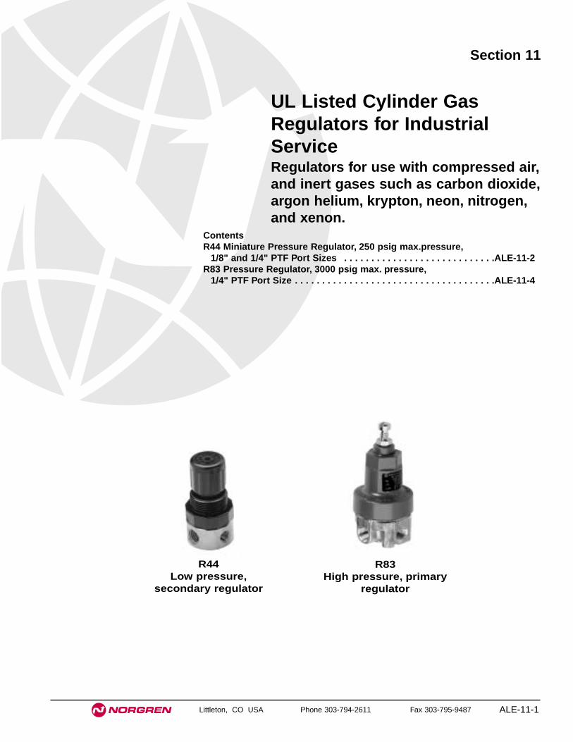
Littleton, CO USA Phone 303-794-2611 Fax 303-795-9487 ALE-11-1
Section 11
ContentsR44 Miniature Pressure Regulator, 250 psig max.pressure,
1/8" and 1/4" PTF Port Sizes . . . . . . . . . . . . . . . . . . . . . . . . . . . .ALE-11-2R83 Pressure Regulator, 3000 psig max. pressure,
1/4" PTF Port Size . . . . . . . . . . . . . . . . . . . . . . . . . . . . . . . . . . . . .ALE-11-4
UL Listed Cylinder GasRegulators for IndustrialServiceRegulators for use with compressed air,and inert gases such as carbon dioxide,argon helium, krypton, neon, nitrogen,and xenon.
R44Low pressure,
secondary regulator
R83High pressure, primary
regulator

See Section ALE-25 for Accessories
ALE-11-2 Littleton, CO USA Phone 303-794-2611 Fax 303-795-9487
R44
● Underwriters Laboratories, Inc. listed (file numberSA1089) for use with air, carbon dioxide, and inertgases. For use with other gases, including oxygen,consult Norgren.
● Compact design
● Brass, zinc, or aluminum bodies with plastic bonnet;brass body also available with brass bonnet
● Plastic bonnet equipped with low torque, non-risingpressure adjusting knob. Snap action knob lockspressure setting when pushed in. Brass bonnetequipped with pressure adjusting screw
● Non-relieving and relieving models. Relieving modelsallow reduction of outlet pressure even when thesystem is dead-ended
● Can be disassembled without the use of tools orremoval from the air line
UL Listed Miniature Pressure Regulator Compressed Air, Carbon Dioxide, Inert Gases
1/8" or 1/4" PTF Port Sizes
Alternative Models 4R 4 ★ ★ ★ ★★ -★ ★ -
Port Size Substitute1/8" 11/4" 2
Threads SubstitutePTF A
Outlet Pressure Adjustment Range† Substitute1 to 10 psig (0.1 to 0.7 bar) A5 to 50 psig (0.3 to 3.5 bar) E5 to 100 psig (0.3 to 7 bar) K
Gauges SubstituteWith GWithout N
Diaphragm SubstituteRelieving RNon relieving N
Body/Bonnet SubstituteAluminum/Plastic 00Brass/Plastic 21Zinc/Plastic 22Brass/Brass 33
* Approximate flow with 100 psig (7 bar) inlet pressure, 90 psig (6.3 bar) set pressureand a 15 psig (1 bar) droop from set.
† Outlet pressure can be adjusted to pressures in excess of, and less than, thosespecified. Do not use these units to control pressures outside of the specified ranges.
Ordering Information. Models listed include PTF threads, relieving diaphragm, 5 to 100 psig (0.3 to 7 bar) outlet pressure adjustment range†,and without gauge.
Body Bonnet Medium Port PTF Model Flow* scfm (dm3/s) Weight lb (kg)Aluminum Plastic Air, inert 1/8" R44-100-RNKA 10 (4.7) 0.23 (0.11)
gases 1/4" R44-200-RNKA 10 (4.7) 0.23 (0.11)Brass Plastic Air, CO2, 1/8" R44-121-RNKA 10 (4.7) 0.45 (0.21)
inert gases 1/4" R44-221-RNKA 10 (4.7) 0.45 (0.21)Zinc Plastic Air, inert 1/8" R44-122-RNKA 10 (4.7) 0.31 (0.14)
gases 1/4" R44-222-RNKA 10 (4.7) 0.31 (0.14)Brass Brass Air, CO2, 1/8" R44-133-RNKA 10 (4.7) 0.54 (0.25)
inert gases 1/4" R44-233-RNKA 10 (4.7) 0.54 (0.25)

R44 Mini Regulator for Air, Carbon Dioxide, Inert Gases
ALE-11-3
All Dimensions in Inches (mm)
Littleton, CO USA Phone 303-794-2611 Fax 303-795-9487
Technical DataFluid: Compressed air, carbon dioxide, inert gasesMaximum pressure: 250 psig (17 bar)Operating temperature: -30° to 150°F (-34° to 66°C) *
* Air supply must be dry enough to avoid ice formation at temperatures below 35°F (2°C).Typical flow at 100 psig (7 bar) inlet pressure, 90 psig (6.3 bar) set pressure and a
droop of 15 psig 1 bar() from set: 10 scfm (4.7 dm3/s) Gauge ports: 1/8" PTFMaterials
Body and bonnetR44-100/-200: Aluminum body; acetal plastic bonnetR44-121/-221: Brass body; acetal plastic bonnetR44-122/-222: Zinc body; acetal plastic bonnet R44-133/-233: Brass body; brass bonnet
Valve: Brass/nitrileValve seat: AcetalElastomers: Nitrile
PORT SIZE: 1/4"SPRING RANGE: 5 to 100 psig (0.3 to 7 bar)INLET PRESSURE: 100 psig (7 bar)
AIR FLOW CHARACTERISTICS
0 2 4 6 8 10 dm3/s
AIR FLOW
0 4 8 12 16 20 scfm
OU
TL
ET
PR
ES
SU
RE
8
6
4
2
0
bar
100
80
60
40
20
0
psi
g
Typical Performance Characteristics
0.91
(23)
2.46
(63
)
2.86
(73
)
1.1 (28)
Models R44-100/-200 and R44-121/-221 (Aluminum or Brass Body and Plastic Bonnet)
1.50
(38
)
1.50 (38)
Models R44-133/-233(Brass Body and Brass Bonnet)
1.03
(26
) 3.01
(77
)
3.41
(87
)
1.50
(38
)
1.50 (38)
0.95
(24
) 2.52
(64
)
2.91
(75
)
1.1 (28)
1.50
(38
)
1.63 (41)
0.73(19)
0.91(23)
Models R44-122/-222(Zinc Body and Plastic Bonnet)
Panel mounting hole diameter:Models with plastic bonnet: 1.19" (30 mm)Models with brass bonnet: 0.81" (21mm)
Maximum panel thickness: 0.25" (6 mm)
Service KitsItem Type Part number
Service kitRelieving 3407-02Non relieving 3407-01
Service kit includes slip ring, diaphragm, standard valve seat withseal, valve, valve spring.

See Section ALE-25 for Accessories
ALE-11-4 Littleton, CO USA Phone 303-794-2611 Fax 303-795-9487
R83
● Underwriters Laboratories, Inc. listed (file numberSA1089) for use with air, argon, carbon dioxide,helium, krypton, neon, nitrogen, xenon. For use withother gases, including oxygen, consult Norgren.
● Non-relieving and relieving models. Relieving modelsallow reduction of outlet pressure even when thesystem is dead-ended
● Two high pressure inlet ports and two regulatedpressure outlet ports
● Diametrically opposite inlet ports provide easymanifolding of several regulators
● Easily replaceable valve cartridge contains valve,valve seat, valve spring, and filter element
UL Listed Pressure Regulator forIndustrial Cylinder Gas 1/4" PTF Port Size
Ordering Information. Models listed include PTF threads, relieving diaphragm, 5 to 125 psig (0.3 to 8.5 bar) outlet pressure adjustment
range†, and without gauge.
Port Model Flow * scfm dm3/s() Weight lb (kg)1/4" R83-200-RNLA 11 (5.2) 1.3 (0.59)
Alternative Models - AN★ ★2 0 -8 0R 3
Outlet Pressure Adjustment Ranges † Substitute2 to 50 psig (0.1 to 3.5 bar) E5 to 125 psig (0.3 to 8.5 bar) L10 to 175 psig (0.7 to 12 bar) N
Diaphragm SubstituteRelieving RNon relieving N
* Approximate flow with 1000 psig (69 bar) inlet pressure, 60 psig (4 bar) set pressure and a 5 psig (0.35 bar) droop from set.
† Outlet pressure can be adjusted to pressures in excess of, and less than, those specified. Do not use these units to control pressures outside of the specified ranges.

R83 Pressure Regulator for Industrial Cylinder Gas
ALE-11-5
All Dimensions in Inches (mm)
Littleton, CO USA Phone 303-794-2611 Fax 303-795-9487
Technical DataFluid: Air, argon, carbon dioxide, helium, krypton, neon, nitrogen, and xenon. For
use with other gases, including oxygen, consult Norgren. Do not use the R83regulator in beverage dispensing applications. Other Norgren regulators (R81for soft drink, R82 for beer, R84 for carbonators) are available for use indispensing systems.
Maximum pressure: 3000 psig (207 bar)Operating temperature: -30° to 140°F (-34° to 60°C) *
* Fluid must be dry enough to avoid ice formation at temperatures below 35°F (2°C).Typical flow at 1000 psig (69 bar) inlet pressure, 60 psig (4 bar) set pressure and a
droop of 5 psig (0.35 bar) from set: 11 scfm (5.2 dm3/s) Materials
Body: BrassBonnet: ZincCartridge valve: Teflon, brass, stainless steelDiaphragm: Acetal and nitrileSeals: Nitrile
PORT SIZE: 1/4"SPRING RANGE: 5 to 125 psig (0.3 to 8.5 bar)INLET PRESSURE: 1000 psig (69 bar)
0 1 2 3 4 5 dm3/s
FLOW
0 2 4 6 8 10 12 scfm
OU
TL
ET
PR
ES
SU
RE
8
6
4
2
0
bar
100
80
60
40
20
0
psi
g
FLOW CHARACTERISTICS - CO2
Typical Performance Characteristics
30°
1.66 (42)
1.90 (48)
4.41
(11
2)
2.10 (53)
0.40
(10
)
Mounting Holes (2 Places)0.18" (4.6mm) dia. by 0.39 (10mm) deep.Use 10-32 thread forming screws.
Service KitsItem Type Part number
Service kitsDiaphragm, relieving 570-51Diaphragm, non relieving 570-10Valve cartridge 5086-55
Valve cartridge includes the sealed cartridge and cartridge o-ring.
WarningThese products are intended for use with industrial
compressed air, argon, carbon dioxide, helium, krypton, neon,nitrogen, and xenon. Do not use these products wherepressures and temperatures can exceed those listed under‘Technical Data’.
Before using these products with fluids other than thosespecified, for non-industrial applications, life-support systems, orother applications not within published specifications, consultNorgren.
Through misuse, age, or malfunction, components used influid power systems can fail in various modes. The systemdesigner is warned to consider the failure modes of allcomponent parts used in fluid power systems and to provideadequate safeguards to prevent personal injury or damage toequipment in the event of such failure.
System designers must provide a warning to endusers in the system instructional manual if protectionagainst a failure mode cannot be adequately provided.
System designers and end users are cautioned to reviewspecific warnings found in instruction sheets packed andshipped with these products.


Littleton, CO USA Phone 303-794-2611 Fax 303-795-9487 ALE-12-1
Section 12
R84 Regulator and C84 Regulator Configurations for Soft Drink Carbonator Service, 1/4" PTF . . . . . . . . . .ALE-12-2
R81 Regulator and C81 Regulator Configurations for Soft Drink Dispensing Systems, 1/4" PTF . . . . . . . . .ALE-12-6
R82 Regulator for Beer Dispensing Systems, 1/4" PTF . .ALE-12-12
U.L. Listed BeverageRegulatorsCylinder Gas Pressure (CO2)Regulators for Soft Drink andBeer dispensing systems.
R84 R81 R82

See Section ALE-25 for Accessories
Littleton, CO USA Phone 303-794-2611 Fax 303-795-9487
R84 Regulator and C84 Configurations
● Underwriters Laboratories, Inc. listed (file numberSA1089)
● Integral relief valve easily replaced withoutdisassembly of regulator and without affecting reliefpressure setting
● Back flow check valve, or manifold with integralcheck valve at each outlet, can be installed inregulator outlet port. Manifolds available with 3 or 5outlets and include one outlet cap.
● Relieving diaphragm allows outlet pressure setting tobe reduced even though the system is dead-ended.Pressure downstream of check valves will not bereduced.
● Easily replaceable valve cartridge contains valve,valve seat, valve spring, and filter element
● Two high pressure ports (inlet and primary gauge)and two regulated pressure ports (outlet andsecondary gauge)
● Bonnet wrench hex same size as tank adapter - onewrench fits both
UL Listed, Cylinder Gas Pressure Regulator1/4" PTF Port Size, CO2 Regulator for Soft Drink Carbonator
Technical DataFluid: Carbon dioxide. The R84 regulator is designed to be used exclusively as a
carbonator regulator in soft drink dispensing systems to control cylinder gas
(carbon dioxide) pressure to the carbonator tank. Other Norgren regulators
(R81 for soft drink syrup containers, R82 for beer, R83 for industrial cylinder
gases) are available for use in other systems.
Maximum pressure: 3000 psig (207 bar)
Operating temperature: 0° to 140°F (-18° to 60°C)
Integral relief valve cracking pressure:
150 ± 5 psig (10.4 ± 0.33 bar)
Materials:
Body: Brass
Bonnet: Zinc
Valve cartridge: Teflon, brass, stainless steel
Diaphragm: Acetal and nitrile
Relief valve: Brass, polycarbonate, nitrile, aluminum
Seals: Nitrile
NOTE
The integral relief valve on the R84 regulator does not meet the
requirements of Paragraph 4.5c of NSDA Pamphlet TD02, Installation
and Operational Procedures for Pressurized Soft Drink Dispensing
Systems, dated July,1980. The end cap on the relief valve is color coded
red for visual identification and is for use only on the Norgren R84
regulator.
ALE-12-2

R84, C84 Beverage Regulators
Littleton, CO USA Phone 303-794-2611 Fax 303-795-9487 ALE-12-3
†† The listed check valves and manifolds with integral check valves are designed for use with Norgren R84 regulators and C84 regulator configurations. They are notrecommended for use with other regulators and regulator configurations unless separate pressure relief protection is provided in each of the outlet lines.
Ordering Information. Models listed include integral relief valve with cracking pressure of 150 ± 5 psig (10.4 ± 0.33 bar), PTF threads,
relieving diaphragm, 5 to 125 psig (0.34 to 8.6 bar) outlet pressure adjustment range†. A gauge is not included.
Port Model Weight lb (kg)1/4" R84-200-MNLA 1.3 (0.59)
Pipe Plug, Hex Socket Hex Nipple Union Adapter with CapWall Mounting Bracket 1/4" PTF 1/4" PTF male 1/4" PTF to 1/4" tube (45° flare)
Strap Type: 5095-51 2891-97 18-006-067 18-006-068Adapter only: 18-006-027
Cap only: 3302-50
Nitrogen Service Carbon Dioxide ServiceCylinder Connector Cylinder Connector
2" (Ø 50 mm) diameter, 1/4" PTF connection 0.906-14 RH external thread 0.830-14 RH internal thread15 psig (1 bar): 18-013-082 CGA No. 580: 18-008-004 1.44" (37 mm) long nipple
30 psig (2 bar), UL Listed: 18-013-030 CGA No. 320: 18-008-00260 psig (4 bar), UL Listed: 18-013-083 2.25" (57 mm) long nipple
100 psig (7 bar), UL Listed: 18-013-084 18-008-015160 psig (11 bar), UL Listed: 18-013-085 Replacement gasket: 1390-02300 psig (20 bar), UL Listed: 18-013-086
2000 psig (135 bar), UL Listed: 18-013-2443000 psig (205 bar), UL Listed: 18-013-087
Inlet Fittings
Check Valve, 1/4" PTF male to 1/4" tube (45°flare): 16-009-001 2 or 3 outlets, 1/4" PTF male to 1/4" tube (45°flare): 3228-54Check Valve, 1/4" PTF male to 1/2-16 BSF: 16-009-002 2 or 3 outlets, 1/4" PTF male to 1/2-16 BSF: 3228-55
Check Valve, 1/4" PTF male to 1/4" PTF female: 16-009-003 4 or 5 outlets, 1/4" PTF male to 1/4" tube (45°flare): 3228-604 or 5 outlets, 1/4" PTF male to 1/2-16 BSF: 3228-61
Manifold extension, 1/4" PTF male to 1/4" PTF female: 2340-50
Single Outlet Fittings - Check Valves ††2 or 3 Port 4 or 5 Port Manifold
Extension
Accessories
Multiple Outlet Fittings - Manifolds with integral check valves ††
† Outlet pressure can be adjusted to pressures in excess of, and less than, that specified. Do not use these units to control pressures outside of the specified range.
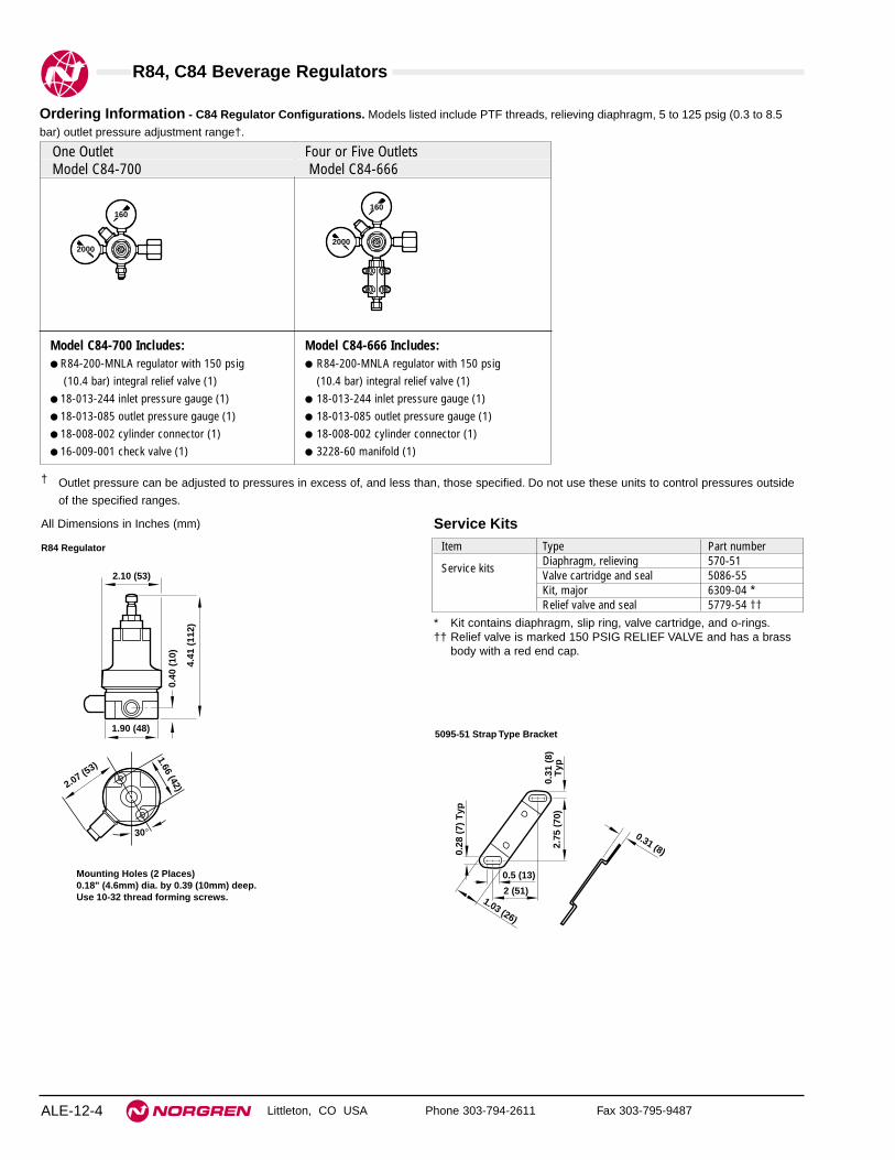
R84, C84 Beverage Regulators
Littleton, CO USA Phone 303-794-2611 Fax 303-795-9487ALE-12-4
All Dimensions in Inches (mm)
Ordering Information - C84 Regulator Configurations. Models listed include PTF threads, relieving diaphragm, 5 to 125 psig (0.3 to 8.5
bar) outlet pressure adjustment range†.
† Outlet pressure can be adjusted to pressures in excess of, and less than, those specified. Do not use these units to control pressures outside
of the specified ranges.
160
2000
160
2000
1.90 (48)
4.41
(11
2)
2.10 (53)
0.40
(10
)
Mounting Holes (2 Places)0.18" (4.6mm) dia. by 0.39 (10mm) deep.Use 10-32 thread forming screws.
30°
1.66 (42)2.07 (53)
R84 Regulator
0.28
(7)
Typ
2.75
(70
)0.
31 (
8)T
yp
2 (51)1.03 (26)
0.31 (8)
0.5 (13)
5095-51 Strap Type Bracket
Service KitsItem Type Part number
Service kitsDiaphragm, relieving 570-51Valve cartridge and seal 5086-55Kit, major 6309-04 *Relief valve and seal 5779-54 ††
* Kit contains diaphragm, slip ring, valve cartridge, and o-rings.†† Relief valve is marked 150 PSIG RELIEF VALVE and has a brass
body with a red end cap.
One Outlet Four or Five OutletsModel C84-700 Model C84-666
Model C84-700 Includes: Model C84-666 Includes:● R84-200-MNLA regulator with 150 psig ● R84-200-MNLA regulator with 150 psig
(10.4 bar) integral relief valve (1) (10.4 bar) integral relief valve (1)● 18-013-244 inlet pressure gauge (1) ● 18-013-244 inlet pressure gauge (1)● 18-013-085 outlet pressure gauge (1) ● 18-013-085 outlet pressure gauge (1)● 18-008-002 cylinder connector (1) ● 18-008-002 cylinder connector (1)● 16-009-001 check valve (1) ● 3228-60 manifold (1)

R84, C84 Beverage Regulators
Littleton, CO USA Phone 303-794-2611 Fax 303-795-9487 ALE-12-5
WARNINGFor safety in systems using Norgren Model R84 regulators, thefollowing procedures must be followed.1. Pressure relief valves of sufficient capacity must always be
used in the secondary (outlet) lines downstream of eachpressure regulator, whether as an integral part of theregulator, as is the case with Norgren Model R84 Regulator,or separately installed elsewhere in the outlet lines. Do notremove or attempt to adjust, plug, block or otherwise defeatthe purpose of the relief valve. Do not replace a relief valvewith any but an identical model. The relief valve used on theR84 regulator is preset and marked 150 PSIG RELIEFVALVE. Replace only with the same 150 psig relief valve,part number 5779-54. The end cap on the 5779-54 reliefvalve is color coded red for visual identification. Failure toprovide a pressure relief valve of sufficient capacity to holdoutlet pressure below the lowest working pressure rating ofany piece of equipment installed in the outlet lines can resultin equipment damage and/or personal injury.
2. A back flow check valve must always be installed at theregulator or at each manifold outlet in liquid dispensingapplications to prevent reverse flow through the regulatorand possible introduction of liquids and other contaminantsinto the regulator.
3. Regulators must not be used where temperature or pressuremay exceed those specified in the Technical Dataparagraph.
4. The accuracy of the indication of pressure gauges canchange, both during shipment (despite care in packaging)and during the service life. If a pressure gauge is to be usedin conjunction with these products and if inaccurateindications may be hazardous to personnel or property, thegauge should be calibrated before initial installation and atregular intervals during use. For gauge standards refer toANSI B40.1.
5. These regulators are not intended for use in life supportsystems, beer dispensing systems, with soft drink product(syrup) containers, or industrial cylinder gas systems.
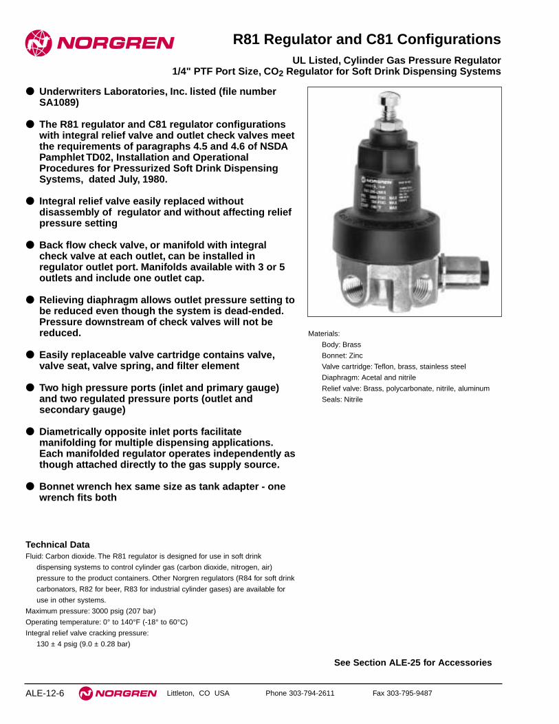
Littleton, CO USA Phone 303-794-2611 Fax 303-795-9487
R81 Regulator and C81 Configurations
● Underwriters Laboratories, Inc. listed (file numberSA1089)
● The R81 regulator and C81 regulator configurationswith integral relief valve and outlet check valves meetthe requirements of paragraphs 4.5 and 4.6 of NSDAPamphlet TD02, Installation and OperationalProcedures for Pressurized Soft Drink DispensingSystems, dated July, 1980.
● Integral relief valve easily replaced withoutdisassembly of regulator and without affecting reliefpressure setting
● Back flow check valve, or manifold with integralcheck valve at each outlet, can be installed inregulator outlet port. Manifolds available with 3 or 5outlets and include one outlet cap.
● Relieving diaphragm allows outlet pressure setting tobe reduced even though the system is dead-ended.Pressure downstream of check valves will not bereduced.
● Easily replaceable valve cartridge contains valve,valve seat, valve spring, and filter element
● Two high pressure ports (inlet and primary gauge)and two regulated pressure ports (outlet andsecondary gauge)
● Diametrically opposite inlet ports facilitatemanifolding for multiple dispensing applications.Each manifolded regulator operates independently asthough attached directly to the gas supply source.
● Bonnet wrench hex same size as tank adapter - onewrench fits both
UL Listed, Cylinder Gas Pressure Regulator1/4" PTF Port Size, CO2 Regulator for Soft Drink Dispensing Systems
Technical DataFluid: Carbon dioxide. The R81 regulator is designed for use in soft drink
dispensing systems to control cylinder gas (carbon dioxide, nitrogen, air)
pressure to the product containers. Other Norgren regulators (R84 for soft drink
carbonators, R82 for beer, R83 for industrial cylinder gases) are available for
use in other systems.
Maximum pressure: 3000 psig (207 bar)
Operating temperature: 0° to 140°F (-18° to 60°C)
Integral relief valve cracking pressure:
130 ± 4 psig (9.0 ± 0.28 bar)
Materials:
Body: Brass
Bonnet: Zinc
Valve cartridge: Teflon, brass, stainless steel
Diaphragm: Acetal and nitrile
Relief valve: Brass, polycarbonate, nitrile, aluminum
Seals: Nitrile
ALE-12-6
See Section ALE-25 for Accessories

R81, C81 Beverage Regulators
Littleton, CO USA Phone 303-794-2611 Fax 303-795-9487 ALE-12-7
† Outlet pressure can be adjusted to pressures in excess of, and less than, those specified. Do not use these units to control pressures outside of the specified ranges.†† The listed check valves and manifolds with integral check valves are designed for use with Norgren R81 regulators and C81 regulator configurations. They are not
recommended for use with other regulators and regulator configurations unless separate pressure relief protection is provided in each of the outlet lines.* The 16-006-107 check and relief valve meets the pressure and flow requirements of paragraphs 4.5 and 4.6 of NSDA Pamphlet TD02, Installation and Operational
Procedures for Pressurized Soft Drink Dispensing Systems, dated July, 1980.** Check valves, or manifolds with integral check valves, must be installed in the outlet ports of the wye when the wye is installed in the outlet port of the Norgren R81
regulator.
Ordering Information. Models listed include integral relief valve with cracking pressure of 130 ± 4 psig (9.0 ± 0.28 bar), PTF threads,
relieving diaphragm, 5 to 100 psig (0.34 to 6.9 bar) outlet pressure adjustment range†. A gauge is not included.
Port Model Weight lb (kg)1/4" R81-200-LNKA 1.3 (0.59)
Alternative Models - ANL ★2 0 -8 0R 1Outlet Pressure Adjustment Ranges † Substitute1 to 25 psig (0.07 to 1.7 bar) T2 to 50 psig (0.14 to 3.4 bar) E5 to 100 psig (0.34 to 6.9 bar) K
Pipe Plug, Hex Socket Hex Nipple Union Adapter with CapWall Mounting Bracket 1/4" PTF 1/4" PTF male 1/4" PTF to 1/4" tube (45° flare)
Strap Type: 5095-51 2891-97 18-006-067 18-006-068Adapter only: 18-006-027
Cap only: 3302-50
Nitrogen Service Carbon Dioxide ServiceCylinder Connector Cylinder Connector
2" (50 mm) diameter, 1/4 PTF connection 0.906-14 RH external thread 0.830-14 RH internal thread15 psig (1 bar): 18-013-082 CGA No. 580: 18-008-004 1.44" (27 mm) long nipple
30 psig (2 bar), UL Listed: 18-013-030 CGA No. 320: 18-008-00260 psig (4 bar), UL Listed: 18-013-083 2.25" (57 mm) long nipple
100 psig (7 bar), UL Listed: 18-013-084 18-008-015160 psig (11 bar), UL Listed: 18-013-085 Replacement gasket: 1390-02300 psig (20 bar), UL Listed: 18-013-086
2000 psig(135 bar), UL Listed: 18-013-2443000 psig (205 bar), UL Listed: 18-013-087
Inlet Fittings
Manifolds with integral check valves †† Streamline Wye **Check Valve, 1/4" PTF male to 1/4" tube (45° flare): 16-009-001 2 or 3 outlets, 1/4" PTF male to 1/4" tube (45° flare): 3228-54 1/4" NPT male to
Check Valve, 1/4" PTF male to 1/2-16 BSF: 16-009-002 2 or 3 outlets, 1/4" PTF male to 1/2-16 BSF: 3228-55 1/4" NPT female: 16-006-107Check Valve, 1/4" PTF male to 1/4" PTF female: 16-009-003 4 or 5 outlets, 1/4" PTF male to 1/4" tube (45° flare): 3228-60
Check and Relief Valve, 4 or 5 outlets, 1/4" PTF male to 1/2-16 BSF: 3228-611/4" PTF male to 1/4" tube (45° flare): 16-006-107 Manifold extension, 1/4" PTF male to 1/4" PTF female: 2340-50
Single Outlet FittingsCheck Valve†† Check Valve†† Check and Relief Valve, *
Relief cracking pressure:130 ± 4 psig
(9.0 ± 0.28 bar)
2 or 3 Port 4 or 5 Port ManifoldExtension
Accessories
Multiple Outlet Fittings

R81, C81 Beverage Regulators
Littleton, CO USA Phone 303-794-2611 Fax 303-795-9487ALE-12-8
Model C81-700 (One Outlet) Model C81-702 (One Outlet) Model C81-651 (One Outlet)
Model C81-700 Includes: Model C81-702 Includes: Model C81-651 Includes:● R81-200-LNKA regulator (1) ● R81-200-LNKA regulator (1) ● R81-200-LNKA regulator (1)● 18-013-244 (2000 psi) inlet pressure gauge (1)) ● 18-013-244 (2000 psi) inlet pressure gauge (1) ● 18-013-244 (2000 psi) inlet pressure gauge (1)● 18-013-085 (160 psi) outlet pressure gauge (1) ● 18-013-084 (100 psi) outlet pressure gauge (1) ● 18-013-084 (100 psi) outlet pressure gauge (1)● 18-008-002 cylinder connector (1) ● 18-008-002 cylinder connector (1) ● 18-008-002 cylinder connector (1)● 16-009-001 check valve (1) ● 16-009-001 check valve (1) ● 16-009-002 check valve (1)
160
2000
Model C81-269 (One Outlet) Model C81-684 (One Outlet)
Model C81-269 Includes: Model C81-684 Includes:● R81-200-LNEA regulator (1) ● R81-200-LNKA regulator (1) ● 18-013-244 (2000 psi) inlet pressure gauge (1) ● 2891-97 pipe plug (1)● 18-013-083 (60 psi) outlet pressure gauge (1) ● 18-013-085 (160 psi) outlet pressure gauge (1)● 18-008-002 cylinder connector (1) ● 18-008-002 cylinder connector (1)● 16-009-001 check valve (1) ● 16-009-001 check valve (1)
Model C81-685 (Two or Three Outlets)
Model C81-685 Includes:● R81-200-LNKA regulator (1)● 18-013-244 (2000 psi) inlet pressure gauge (1)● 18-013-085 (160 psi) outlet pressure gauge (1)● 18-008-002 cylinder connector (1)● 3228-54 manifold (1)
100
2000
100
2000
16060
2000
160
2000
Cylinder Connected,Two Regulator Configurations
Cylinder Connected, One Regulator Configurations
Model C81-254 (Two Outlets) Model C81-652 (Two Outlets)
Model C81-254 Includes: Model C81-652 Includes:● R81-200-LNEA regulator (1) ● R81-200-LNKA regulator (2)● R81-200-LNKA regulator (1) ● 18-013-244 (2000 psi) inlet pressure gauge (1)● 18-013-244 (2000 psi) inlet pressure gauge (1) ● 18-013-084 (100 psi) outlet pressure gauge (2)● 18-013-083 (60 psi) outlet pressure gauge (1) ● 18-006-067 hex nipple (1)● 18-013-085 (160 psi) outlet pressure gauge (1) ● 18-008-002 cylinder connector (1)● 18-006-067 hex nipple (1) ● 16-009-002 check valve (2)● 18-008-002 cylinder connector (1)● 16-009-001 check valve (2)
Model C81-573 (Four to Six Outlets)
Model C81-573 Includes:● R81-200-LNKA regulator (2)● 18-013-244 (2000 psi) inlet pressure gauge (1)● 18-013-085 (160 psi) outlet pressure gauge (2)● 18-006-067 hex nipple (1)● 18-008-002 cylinder connector (1)● 3228-55 manifold (2)
100100
2000
16060
2000
160
2000
160
2 to 50 psig range†5 to 100 psig range†
5 to 100 psig range† 5 to 100 psig range†
2 to 50 psig range† 5 to 100 psig range†5 to 100 psig range†
5 to 100 psig range† 5 to 100 psig range† 5 to 100 psig range†

Littleton, CO USA Phone 303-794-2611 Fax 303-795-9487 ALE-12-9
Model C81-541 (One Outlet)
Model C81-541 Includes:● R81-200-LNKA regulator with 9,0 bar
(130 psig) integral relief valve (1)● 18-013-084 (100 psi) outlet pressure gauge (1)● 18-006-027 half-union adapter (1)● 18-006-068 half-union adapter with cap (1)● 16-009-001 check valve (1)● 5095-51 mounting bracket (1)
100
Wall Mounted, One Regulator Configurations
5 to 100 psig range†
Model C81-554 (Two or Three Outlets)
Model C81-554 Includes:● R81-200-LNKA regulator with 9,0 bar
(130 psig) integral relief valve (1)● 18-013-084 (100 psi) outlet pressure gauge (1)● 18-006-027 half-union adapter (1)● 18-006-068 half-union adapter with cap (1)● 3228-54 manifold (1)● 5095-51 mounting bracket (1)
100
5 to 100 psig range†
Model C81-559 (Four or Five Outlets)
Model C81-559 Includes:● R81-200-LNKA regulator with 9,0 bar
(130 psig) integral relief valve (1)● 18-013-084 (100 psi) outlet pressure gauge (1)● 18-006-027 half-union adapter (1)● 18-006-068 half-union adapter with cap (1)● 3228-60 manifold (1)● 5095-51 mounting bracket (1)
100
5 to 100 psig range†
Model C81-540 (Three or Four Outlets)
Model C81-540 Includes:● R81-200-LNKA regulator (2)● 18-013-084 (100 psi) outlet pressure gauge (2)● 18-006-067 hex nipple (1)● 18-006-027 half-union adapter (1)● 18-006-068 half-union adapter with cap (1)● 16-009-001 check valve (1)● 3228-54 manifold (1)● 5095-51 mounting bracket (2)
100100
Wall Mounted,Two Regulator Configurations
5 to 100 psig range†
Model C81-570 (Four to Six Outlets)
Model C81-570 Includes:● R81-200-LNKA regulator (2)● 18-013-084 (100 psi) outlet pressure gauge (2)● 18-006-067 hex nipple (1)● 18-006-027 half-union adapter (1)● 18-006-068 half-union adapter with cap (1)● 2340-50 manifold extension (1)● 3228-54 manifold (2)● 5095-51 mounting bracket (2)
1001005 to 100 psig range†
Model C81-657 (Five or Six Outlets)
Model C81-657 Includes:● R81-200-LNKA regulator (2)● 18-013-084 (100 psi) outlet pressure gauge (2)● 18-006-067 hex nipple (1)● 18-006-027 half-union adapter (1)● 18-006-068 half-union adapter with cap (1)● 16-009-001 check valve (1)● 3228-60 manifold (1)● 5095-51 mounting bracket (2)
100100
5 to 100 psig range†
Wall Mounted,Three Regulator Configuration
Model C81-724 (Five to Eight Outlets)
Model C81-724 Includes:● R81-200-LNKA regulator (2) ● 2340-50 manifold extension (1)● 18-013-084 (100 psi) ● 3228-56 manifold (1) - Same as
outlet pressure gauge (2) 3228-54 but includes two caps● 18-006-067 hex nipple (1) ● 3228-60 manifold (1)● 18-006-027 half-union adapter (1) ● 5095-51 mounting bracket (2)● 18-006-068 half-union adapter (1)
1001005 to 100 psig range†
Model C81-324 (Six to Nine Outlets)
Model C81-324 Includes:● R81-200-LNKA regulator (3) ● 2340-50 manifold extension (1)● 18-013-084 (100 psi) ● 3228-54 manifold (3)
outlet pressure gauge (3) ● 5095-51 mounting bracket (2)● 18-006-067 hex nipple (2)● 18-006-027 half-union adapter (1)● 18-006-068 half-union adapter (1)
100 1001005 to 100 psig range†
† Outlet pressure can be adjusted to pressures in excess of, and less than, those specified. Do not use these units to control pressures outside of thespecified ranges.
R81, C81 Beverage Regulators

R81, C81 Beverage Regulators
Littleton, CO USA Phone 303-794-2611 Fax 303-795-9487ALE-12-10
All Dimensions in Inches (mm)
Service KitsItem Type Part number
Service kitsDiaphragm, relieving 570-51Valve cartridge and seal 5086-55Kit, major 6309-04 *Relief valve and seal 5779-55 †
* Kit contains diaphragm, slip ring, valve cartridge, and o-rings.† Relief valve is marked 130 PSIG RELIEF VALVE and has a brass
body with a black end cap.
1.90 (48)
4.41
(11
2)
2.10 (53)
0.40
(10
)
Mounting Holes (2 Places)0.18" (4.6 mm) dia. by 0.39 (10 mm) deep.Use 10-32 thread forming screws.
30°
1.66 (42)2.07 (53)
0.28
(7)
Typ
2.75
(70
)0.
31 (
8)T
yp
2 (51)1.03 (26)
0.31 (8)
0.5 (13)
5095-51 Strap Type Bracket
R81 Regulator

R81, C81 Beverage Regulators
Littleton, CO USA Phone 303-794-2611 Fax 303-795-9487 ALE-12-11
WARNINGSoft drink dispensing systems must be designed, installed, andoperated in accordance with the guidelines set forth in NSDApamphlet TD02, Installation and Operational Procedures forPressurized Soft Drink Dispensing Systems, dated July,1980 or subsequent revisions.1.Pressure relief valves of sufficient capacity must always be
used in the secondary (outlet) lines downstream of eachpressure regulator, whether as an integral part of theregulator, as is the case with Norgren Model R81 Regulator,or separately installed elsewhere in the outlet lines. Do notremove or attempt to adjust, plug, block or otherwise defeatthe purpose of the relief valve. Do not replace a relief valvewith any but an identical model. The relief valve used on theR81 regulator is preset and marked 130 PSIG RELIEFVALVE. Replace only with the same 130 psig relief valve,part number 5779-55. The end cap on the 5779-55 reliefvalve is color coded black for visual identification. Failure toprovide a pressure relief valve of sufficient capacity to holdoutlet pressure below the lowest working pressure rating ofany piece of equipment installed in the outlet lines can resultin equipment damage and/or personal injury.
2. A back flow check valve must always be installed at theregulator or at each manifold outlet in liquid dispensingapplications to prevent reverse flow through the regulatorand possible introduction of liquids and other contaminantsinto the regulator.
3. Regulators must not be used where temperature or pressuremay exceed those specified in the Technical Dataparagraph.
4. The accuracy of the indication of pressure gauges canchange, both during shipment (despite care in packaging)and during the service life. If a pressure gauge is to be usedin conjunction with these products and if inaccurateindications may be hazardous to personnel or property, thegauge should be calibrated before initial installation and atregular intervals during use. For gauge standards refer toANSI B40.1.
5. These regulators are not intended for use in life supportsystems, beer dispensing systems, soft drink carbonator systems, or industrial cylinder gas systems.

Littleton, CO USA Phone 303-794-2611 Fax 303-795-9487
R82 Regulator
● Underwriters Laboratories, Inc. listed (file numberSA1089)
● The R82 regulator with integral relief valve meets therequirements of Proposed Section 9.7, Draught BeerDispensing Equipment and Related Components(Seventh Draft dated October 17, 1980), of ANSI-ASME F2.1-1975, Food, Drug, and BeverageEquipment.
● Integral relief valve easily replaced withoutdisassembly of regulator and without affecting reliefpressure setting
● Back flow check valve, or manifold with integralcheck valve at each outlet, can be installed inregulator outlet port. Manifolds available with 3 or 5outlets and include one outlet cap.
● Relieving diaphragm allows outlet pressure setting tobe reduced even though the system is dead-ended.Pressure downstream of check valves will not bereduced.
● Easily replaceable valve cartridge contains valve,valve seat, valve spring, and filter element
● Two high pressure ports (inlet and primary gauge)and two regulated pressure ports (outlet andsecondary gauge)
● Diametrically opposite inlet ports facilitatemanifolding for multiple dispensing applications.Each manifolded regulator operates independently asthough attached directly to the gas supply source.
● Bonnet wrench hex same size as tank adapter - onewrench fits both
UL Listed, Cylinder Gas Pressure Regulator1/4" PTF, CO2 Regulator for Beer Dispensing Systems
Technical DataFluid: Carbon dioxide. The R82 regulator is designed for use in beer dispensing
systems to control cylinder gas (carbon dioxide) pressure to the beer keg.
Other Norgren regulators (R81 for soft drink syrup containers, R84 for soft drink
carbonators, R83 for industrial cylinder gases) are available for use in other
systems.
Maximum pressure: 3000 psig (207 bar)
Operating temperature: 0° to 140°F (-18° to 60°C)
Maximum outlet pressure adjustment limit: Factory set at 40 to 45 psig (2.8 to 3.1 bar)
Integral relief valve cracking pressure:
60 ± 4 psig (4.1 ± 0.28 bar)
Materials:
Body: Brass
Bonnet: Zinc
Valve cartridge: Teflon, brass, stainless steel
Diaphragm: Acetal and nitrile
Relief valve: Brass, polycarbonate, nitrile, aluminum
Seals: Nitrile
ALE-12-12
See Section ALE-25 for Accessories

R82 Beverage Regulators
Littleton, CO USA Phone 303-794-2611 Fax 303-795-9487 ALE-12-13
† Outlet pressure can be adjusted to pressures in excess of, and less than, that specified. Do not use these units to control pressures outside of
the specified range.
†† The listed check valves and manifolds with integral check valves are designed for use with Norgren R82 regulators. They are not
recommended for use with other regulators unless separate pressure relief protection is provided in each of the outlet lines.
Ordering Information. Models listed include integral relief valve with cracking pressure of 60 ± 4 psig (4.1 ± 0.28 bar), PTF threads, relieving
diaphragm, 2 to 45 psig (0.14 to 3.1 bar) outlet pressure adjustment range†. A gauge is not included.
Port Model Weight lb (kg)1/4" R82-200-ENEA 1.3 (0.59)
Pipe Plug, Hex Socket Hex Nipple Union Adapter with CapWall Mounting Bracket 1/4" PTF 1/4" PTF male 1/4" PTF to 1/4" tube (45° flare)
Strap Type: 5095-51 2891-97 18-006-067 18-006-068Adapter only: 18-006-027
Cap only: 3302-50
Nitrogen Service Carbon Dioxide ServiceCylinder Connector Cylinder Connector
Ø 50 mm (2") diameter, 1/4" PTF connection 0.906-14 RH external thread 0.830-14 RH internal thread15 psig (1 bar): 18-013-082 CGA No. 580: 18-008-004 1.44" (37 mm) long nipple
30 psig (2 bar), UL Listed: 18-013-030 CGA No. 320: 18-008-00260 psig (4 bar), UL Listed: 18-013-083 2.25" (57 mm) long nipple
100 psig (7 bar), UL Listed: 18-013-084 18-008-015160 psig (11 bar), UL Listed: 18-013-085 Replacement gasket: 1390-02300 psig (20 bar), UL Listed: 18-013-086
2000 psig (135 bar), UL Listed: 18-013-2443000 psig (205 bar), UL Listed: 18-013-087
Inlet Fittings
Check Valve, 1/4" PTF male to 1/4" tube (45° flare): 16-009-001 2 or 3 outlets, 1/4" PTF male to 1/4" tube (45° flare): 3228-54Check Valve, 1/4" PTF male to 1/2-16 BSF: 16-009-002 2 or 3 outlets, 1/4" PTF male to 1/2-16 BSF: 3228-55
Check Valve, 1/4" PTF male to 1/4" PTF female: 16-009-003 4 or 5 outlets, 1/4" PTF male to 1/4" tube (45° flare): 3228-604 or 5 outlets, 1/4" PTF male to 1/2-16 BSF: 3228-61
Manifold extension, 1/4" PTF male to 1/4" PTF female: 2340-50
Single Outlet Fittings - Check Valves ††2 or 3 Port 4 or 5 Port Manifold
Extension
Accessories
Multiple Outlet Fittings - Manifolds with integral check valves ††

R82 Beverage Regulators
Littleton, CO USA Phone 303-794-2611 Fax 303-795-9487ALE-12-14
All Dimensions in Inches (mm)
Mounting Holes (2 Places)0.18" (4.6 mm) dia. by 0.39" (10 mm) deep.Use 10-32 thread forming screws.
1.90 (48)
4.75
(12
1)
2.10 (53)
0.40
(10
)
30°
1.66 (42)2.07 (53)
R82 Regulator
0.28
(7)
Typ
2.75
(70
)0.
31 (
8)T
yp
2 (51)1.03 (26)
0.31 (8)
0.5 (13)
5095-51 Strap Type Bracket
Service KitsItem Type Part number
Service kitsDiaphragm, relieving 570-51Valve cartridge and seal 5086-55Kit, major 6309-04 *Relief valve and seal 5779-56 †
* Kit contains diaphragm, slip ring, valve cartridge, and o-rings.† Relief valve is marked 60 PSIG RELIEF VALVE and has a brass
body with a natural (silver colored) aluminum end cap.
WARNINGBeer dispensing systems must be designed,installed, and operated in accordance with theapplicable guidelines such as the proposed Section9.7, Draught Beer Dispensing Equipment andRelated Components (Seventh Draft dated October17, 1980), of ANSI-ASME F2.1-1975, Food, Drugand Beverage Equipment or subsequent revisions.1. Pressure relief valves of sufficient capacity must
always be used in the secondary (outlet) linesdownstream of each pressure regulator, whetheras an integral part of the regulator, as is the casewith Norgren Model R82 Regulator, or separatelyinstalled elsewhere in the outlet lines. Do notremove or attempt to adjust, plug, block orotherwise defeat the purpose of the relief valve.Do not replace a relief valve with any but anidentical model. The relief valve used on the R82regulator is preset and marked 60 PSIG RELIEFVALVE. Replace only with the same 60 psig reliefvalve, part number 5779-56. The end cap on the5779-56 relief valve is color coded silver for visualidentification. Failure to provide a pressure reliefvalve of sufficient capacity to hold outlet pressurebelow the lowest working pressure rating of anypiece of equipment installed in the outlet lines canresult in equipment damage and/or personalinjury.
2. A back flow check valve must always be installedat the regulator or at each manifold outlet in liquiddispensing applications to prevent reverse flowthrough the regulator and possible introduction ofliquids and other contaminants into the regulator.
3. Regulators must not be used where temperatureor pressure may exceed those specified in theTechnical Data paragraph.
4. The accuracy of the indication of pressure gaugescan change, both during shipment (despite care inpackaging) and during the service life. If apressure gauge is to be used in conjunction withthese products and if inaccurate indications maybe hazardous to personnel or property, the gaugeshould be calibrated before initial installation andat regular intervals during use. For gaugestandards refer to ANSI B40.1.
5. These regulators are not intended for use in lifesupport systems, soft drink carbonator systems,with soft drink product (syrup) containers, orindustrial cylinder gas systems.
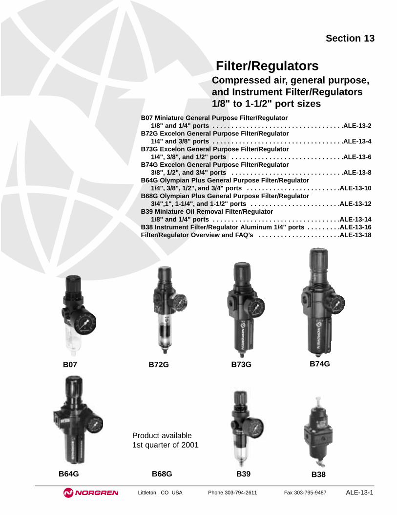
Littleton, CO USA Phone 303-794-2611 Fax 303-795-9487 ALE-13-1
Section 13
B07 Miniature General Purpose Filter/Regulator1/8" and 1/4" ports . . . . . . . . . . . . . . . . . . . . . . . . . . . . . . . . . . .ALE-13-2
B72G Excelon General Purpose Filter/Regulator 1/4" and 3/8" ports . . . . . . . . . . . . . . . . . . . . . . . . . . . . . . . . . . .ALE-13-4
B73G Excelon General Purpose Filter/Regulator 1/4", 3/8", and 1/2" ports . . . . . . . . . . . . . . . . . . . . . . . . . . . . . .ALE-13-6
B74G Excelon General Purpose Filter/Regulator 3/8", 1/2", and 3/4" ports . . . . . . . . . . . . . . . . . . . . . . . . . . . . . .ALE-13-8
B64G Olympian Plus General Purpose Filter/Regulator 1/4", 3/8", 1/2", and 3/4" ports . . . . . . . . . . . . . . . . . . . . . . . . .ALE-13-10
B68G Olympian Plus General Purpose Filter/Regulator 3/4",1", 1-1/4", and 1-1/2" ports . . . . . . . . . . . . . . . . . . . . . . . .ALE-13-12
B39 Miniature Oil Removal Filter/Regulator 1/8" and 1/4" ports . . . . . . . . . . . . . . . . . . . . . . . . . . . . . . . . . .ALE-13-14
B38 Instrument Filter/Regulator Aluminum 1/4" ports . . . . . . . . .ALE-13-16Filter/Regulator Overview and FAQ’s . . . . . . . . . . . . . . . . . . . . . .ALE-13-18
Filter/RegulatorsCompressed air, general purpose,and Instrument Filter/Regulators1/8" to 1-1/2" port sizes
B07 B72G B73G B74G
B64G B39 B38B68G
Product available1st quarter of 2001

See Section ALE-25 for Accessories
Littleton, CO USA Phone 303-794-2611 Fax 303-795-9487
B07
● Compact design
● Full flow gauge ports
● Low torque, non-rising adjusting knob
● Snap action knob locks pressure setting whenpushed in
● Standard relieving models allow reduction of outletpressure even when the system is dead-ended
● Protects air operated devices by removing liquid andsolids contaminants
● Screw-on bowl reduces maintenance time
● Can be disassembled without the use of tools orremoval from the air line
Series 07 General Purpose Filter/Regulator1/8" and 1/4" Port Sizes
ALE-13-2
ISO Symbols
Automatic Drain Relieving
Manual DrainRelieving
Automatic DrainNon Relieving
Manual DrainNon Relieving
Alternative Models - ★★★ ★★ ★ -0 ★B 7
Threads SubstitutePTF AISO Rc taper BISO G parallel G
Drain SubstituteAutomatic AManual M
Port Size Substitute1/8" 11/4" 2
Element Substitute5 µm 140 µm 3
Bowl Relief Type Gauge SubstituteTransparent Relieving Without 01Transparent Relieving With 02Transparent Non-relieving Without 03Transparent Non-relieving With 23Metal Relieving Without 33Metal Relieving With 34Metal Non-relieving Without 35Metal Non-relieving With 36
Outlet Pressure Adjustment Ranges* Substitute1 to 10 psig (0.1 to 0.7 bar) A5 to 50 psig (0.3 to 3.5 bar) E5 to 100 psig (0.3 to 7 bar) K
Ordering Information. Models listed include PTF threads, transparent bowl, relieving diaphragm, gauge, automatic drain, 5 µm element, 5 to100 psig (0.3 to 7 bar) outlet pressure adjustment range* .
Port Size Model Number Flow† scfm (dm3/s) Weight lbs (kg)1/8" B07-101-A1KA 13 (6.2 dm3/s) 0.57 (0.26)1/4" B07-201-A1KA 14 (6.5 dm3/s) 0.57 (0.26)
* Outlet pressure can be adjusted to pressures in excess of, and less than, those specified. Do not use these units to control pressures outside of the specifiedranges.
† Typical flow with 100 psig (7 bar) inlet pressure, 90 psig (6.3 bar) set pressure and a 15 psig (1 bar) droop from set.

B07 Filter/Regulators
Littleton, CO USA Phone 303-794-2611 Fax 303-795-9487 ALE-13-3
All Dimensions in Inches (mm)
Automatic DrainManual Drain
2.13
(54
)
1.63 (41)
1.50 (38)
1.50
(38
)
8.41
(21
4)**
1.12
(28
) 2.67
(68
)
6.44
(16
4)
1.1 (28)
8.26
(21
0)**
1.12
(28
) 2.67
(68
)
6.29
(16
0)
1.1 (28)
** Minimum clearance to remove bowlPanel mounting hole diameter 1.19" (30 mm)Panel thickness: 0.25" (6 mm)
PORT SIZE: 1/4"ELEMENT: 40 µmINLET PRESSURE: 150 psig (10 bar g)RANGE: 5 to 100 psig (0.3 to 7 bar)
FLOW CHARACTERISTICS
0 2 4 6 8 10 dm3/s
AIR FLOW
0 4 8 12 16 20 24 scfm
OU
TL
ET
PR
ES
SU
RE
8
6
4
2
0
bar
g
100
80
60
40
20
0
psi
g
Typical Performance Characteristics
Service KitsItem Type Part number
Service kitRelieving models, 40 µm element 3820-14Non relieving models, 40 µm element 3820-13
Replacement drainsManual 773-03Automatic 3654-02
Service kit includes slip ring, diaphragm, valve seat with o-ring,valve, valve spring, element, element gasket, and bowl o-ring.
Technical DataFluid: Compressed airMaximum pressure
Transparent bowl: 150 psig (10 bar)Metal bowl: 250 psig (17 bar)
Operating temperature*Transparent bowl: 30° to 125°F (-34° to 50°C)Metal bowl: -30° to 150°F (-34° to 65°C)
* Air supply must be dry enough to avoid ice formation at temperatures below 35°F (2°C)
Particle removal: 5 µm or 40 µm filter elementAir quality: Within ISO 8573-1, Class 3 and Class 5 (particulates)Typical flow at 100 psig (7 bar) inlet pressure, 90 psig (6.3 bar) set pressure and a
droop of 15 psig (1 bar) from set1/8" Ports: 13 scfm (6.2 dm3/s) with 5 µm element1/4" Ports: 14 scfm (6.5 dm3/s) with 5 µm element
Nominal bowl size: 1 fluid ounce (31 ml)Gauge ports:
1/8" PTF with PTF main ports1/8" ISO Rc with ISO Rc main ports1/8" ISO Rc with ISO G main ports
Drain connection: Will fit 1/8-27 and 1/8-28 pipe threadAutomatic drain operation: Spitter type drain operates momentarily when a rapid
change in air flow occurs or when the supply pressure is reduced.Materials:
Body: ZincBonnet: AcetalValve: Brass/nitrileValve seat: AcetalBowl
Transparent: PolycarbonateMetal: Zinc
Element: Sintered polypropyleneElastomers: Nitrile
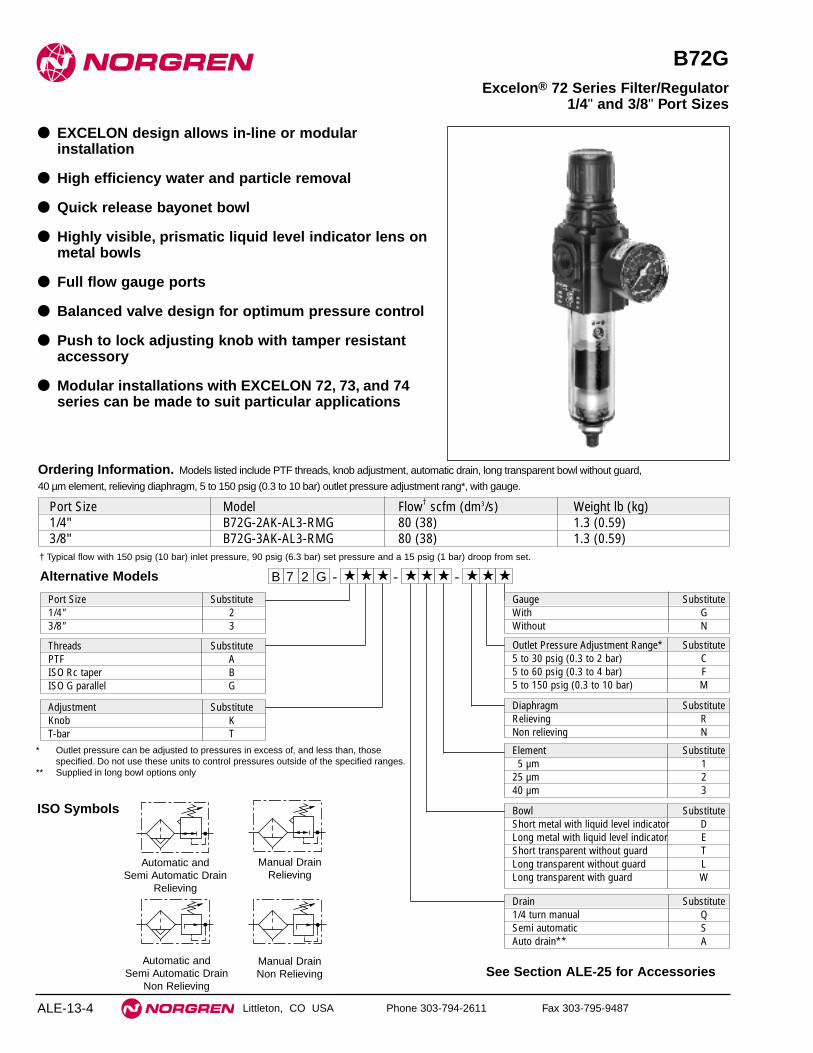
See Section ALE-25 for Accessories
Littleton, CO USA Phone 303-794-2611 Fax 303-795-9487
B72G
● EXCELON design allows in-line or modularinstallation
● High efficiency water and particle removal
● Quick release bayonet bowl
● Highly visible, prismatic liquid level indicator lens onmetal bowls
● Full flow gauge ports
● Balanced valve design for optimum pressure control
● Push to lock adjusting knob with tamper resistantaccessory
● Modular installations with EXCELON 72, 73, and 74series can be made to suit particular applications
Excelon® 72 Series Filter/Regulator 1/4" and 3/8" Port Sizes
ALE-13-4
ISO Symbols
Automatic and Semi Automatic Drain
Relieving
Manual DrainRelieving
Automatic and Semi Automatic Drain
Non Relieving
Manual DrainNon Relieving
Alternative Models
Ordering Information. Models listed include PTF threads, knob adjustment, automatic drain, long transparent bowl without guard,
40 µm element, relieving diaphragm, 5 to 150 psig (0.3 to 10 bar) outlet pressure adjustment rang*, with gauge.
† Typical flow with 150 psig (10 bar) inlet pressure, 90 psig (6.3 bar) set pressure and a 15 psig (1 bar) droop from set.
Port Size Model Flow† scfm (dm3/s) Weight lb (kg)1/4" B72G-2AK-AL3-RMG 80 (38) 1.3 (0.59)3/8" B72G-3AK-AL3-RMG 80 (38) 1.3 (0.59)
B 7 2 -G ★ ★ - ★★ ★ ★
Port Size Substitute1/4" 23/8" 3
Threads SubstitutePTF AISO Rc taper BISO G parallel G
Diaphragm SubstituteRelieving RNon relieving N
Element Substitute5 µm 1
25 µm 240 µm 3
Adjustment SubstituteKnob KT-bar T
- ★★ ★
Drain Substitute1/4 turn manual QSemi automatic SAuto drain** A
Gauge SubstituteWith GWithout N
Outlet Pressure Adjustment Range* Substitute5 to 30 psig (0.3 to 2 bar) C5 to 60 psig (0.3 to 4 bar) F5 to 150 psig (0.3 to 10 bar) M
* Outlet pressure can be adjusted to pressures in excess of, and less than, thosespecified. Do not use these units to control pressures outside of the specified ranges.
** Supplied in long bowl options only
Bowl SubstituteShort metal with liquid level indicator DLong metal with liquid level indicator EShort transparent without guard TLong transparent without guard LLong transparent with guard W

B72G Filter/Regulators
Littleton, CO USA Phone 303-794-2611 Fax 303-795-9487 ALE-13-5
All Dimensions in Inches (mm)
Technical DataFluid: Compressed airMaximum pressure: Transparent bowl: 150 psig (10 bar)
Metal bowl: Manual or semi automatic drain: 250 psig (17 bar)Automatic drain: 150 psig (10 bar)
Operating temperature*: Transparent bowl: -30° to 125°F (-34° to 50°C)Metal bowl: -30° to 150°F (-34° to 65°C)
* Air supply must be dry enough to avoid ice formation at temperatures below 35°F (2°C ).
Particle removal: 5 µm, 25 µm or 40 µm. Within ISO 8573-1, Class 3 and Class 5Typical flow at 150 psig (10 bar) inlet pressure, 90 psig (6.3 bar) set pressure and
a droop of 1 bar (15 psig) from set: 80 scfm (38 dm3/s)Manual drain connection: Will fit 1/8-27 and 1/8-28 pipe threadSemi automatic drain connection: Push on 5/16" (8 mm) ID tubeSemi automatic drain operating conditions (pressure operated):
Bowl pressure required to close drain: Greater than 1.5 psig (0.1 bar)Bowl pressure required to open drain: Less than 1.5 psig (0.1 bar) Minimum air flow required to close drain: 1 scfm (0.5 dm3/s)Manual operation: Lift stem to drain bowl
Automatic drain connection: Will fit 1/8-27 and 1/8-28 pipe thread - Flexible tubewith 3/16" (5mm) minimum I.D. can be connected to the automatic drain. Drainmay fail to operate if the tube I.D. is less than 3/16" (5mm). Avoid restrictions inthe tube.
Automatic drain operating conditions (float operated):Bowl pressure required to close drain: Greater than 5 psig (0.3 bar) Bowl pressure required to open drain: Less than 3 psig (0.2 bar)Minimum air flow required to close drain: 0.2 scfm (0.1 dm3/s)Manual operation: Depress pin inside drain outlet to drain bowl
Gauge ports: 1/8"PTF with PTF main ports1/8" ISO Rc with ISO Rc main ports1/8" ISO Rc with ISO G main ports
Nominal bowl size: Short bowl: 1.9 fluid ounce (56 ml)Long bowl: 2.2 fluid ounce (65 ml)
Materials Body: ZincBonnet: AcetalValve: BrassBowl
Transparent: PolycarbonateGuard for transparent bowl: ZincMetal bowl liquid level indicator lens:
Transparent nylonElement: Sintered polypropyleneElastomers: Neoprene and nitrile
Typical Performance Characteristics
PORT SIZE: 1/4" ELEMENT: 40 µmINLET PRESSURE: 100 psig (7 bar g)RANGE: 5 to 150 psig (0.3 to 10 bar)
FLOW CHARACTERISTICS
0 5 10 15 20 25 dm3/s
AIR FLOW
0 10 20 30 40 50 60 scfm
OU
TL
ET
PR
ES
SU
RE
12
9
6
3
0
bar
g
150
120
90
60
30
0
psi
g
PORT SIZE: 1/4" ELEMENT: 40 µmINLET PRESSURE: 150 psig (10 bar g)RANGE: 5 to 150 psig (0.3 to 10 bar)
FLOW CHARACTERISTICS
0 10 20 30 40 50 dm3/s
AIR FLOW
0 20 40 60 80 100 120 scfm
OU
TL
ET
PR
ES
SU
RE
12
9
6
3
0 b
ar g
150
120
90
60
30
0
psi
g
Short Bowl with 1/4 Turn Manual Drain Short Bowl with
Semi auto Drain Long Bowl with Automatic Drain
Long Bowl with Semi auto Drain
Long Bowl with 1/4 Turn Manual Drain
6.93
(17
6)
7.48
(19
0)
9.84
(25
0) †
5.27
(13
4)2.
89 (
73)
7.27
(18
5)†
1.01
(26
)
5.83
(14
8)
7.83
(19
9) †
5.51
(14
0)
7.52
(19
1) †
3.73
(95
)
8.94
(22
7)†
1.01
(26
)
Knob Adjustment T-bar Adjustment
1.89
(48
)1.
38 (3
5)
1.97 (50)2.48 (63)
1.89
(48
)1.
38 (
35)
1.97 (50)
† Minimum clearance required to remove bowl.
Service KitsItem Type Part Number
Service kitRelieving 4383-500Non relieving 4383-5015 µm 5925-03
Replacement elements 25 µm 5925-0140 µm 5925-02
Liquid level lens kit Prismatic 4380-0301/4 turn manual 619-50
Replacement drains Semi automatic 5379-RKAutomatic 4000-50R
Service kit includes diaphragm assembly, valve assembly, valve spring, louvre o-ring, bowl o-ring, drain seal.
Panel mounting hole diameter 1.57" (40 mm)Panel thickness: 0.16 (4 mm)

See Section ALE-25 for Accessories
Littleton, CO USA Phone 303-794-2611 Fax 303-795-9487
B73G
● Excelon design allows in-line or modular installation
● Quick release bayonet bowl
● Highly visible, prismatic liquid level indicator lens
● Full flow gauge ports
● Balanced valve design minimizes effect of variationin the inlet pressure on the outlet pressure
● Modular installations with Excelon 72, 73, and 74series can be made to suit particular applications
Excelon® 73 Series Filter/Regulator 1/4", 3/8", 1/2" Port Sizes
ALE-13-6
Ordering Information. Models listed include PTF threads, knob adjustment, automatic drain, metal bowl with liquid level indicator, 40 µm element,
relieving diaphragm, 5 to 150 psig (0.3 to 10 bar) outlet pressure adjustment range* with gauge.
† Typical flow with 150 psig (10 bar) inlet pressure, 90 psig (6.3 bar) set pressure and 15 psig (1 bar) droop from set.
Main Port Size Model Number Flow† scfm (dm3/s) Weight lb (kg)1/4" B73G-2AK-AD3-RMG 78 (37) 1.76 (0.82)3/8" B73G-3AK-AD3-RMG 123 (58) 1.76 (0.82)1/2" B73G-4AK-AD3-RMG 123 (58) 1.76 (0.82)
Alternative Models B 7 3 -G ★ ★ - ★★ ★ ★
Threads SubstitutePTF AISO Rc taper BISO G parallel G
Adjustment SubstituteKnob KT-bar T Diaphragm Substitute
Relieving RNon relieving N
Gauge SubstituteWith GWithout N
Bowl SubstituteMetal with liquid level indicator DTransparent with guard PTransparent T
Element Substitute5 µm 125 µm 240 µm 3
- ★★ ★
*Outlet pressure can be adjusted to pressures in excess of, and less than, thosespecified. Do not use these units to control pressures outside of the specified ranges.
**Units with 250 psig (17 bar) outlet pressure range are available only with thestandard metal bowl.
Drain SubstituteAutomatic AManual, 1/4 turn Q
Port Size Substitute1/4" 23/8" 31/2" 4
Outlet Pressure Adjustment Range* Substitute5 to 60 psig (0.3 to 4 bar) F5 to 150 psig (0.3 to 10 bar) M10 to 250 psig (0.7 to 17 bar)** S

B73G Filter/Regulators
Littleton, CO USA Phone 303-794-2611 Fax 303-795-9487 ALE-13-7
All Dimensions in Inches (mm)Technical DataFluid: Compressed airMaximum pressure
Transparent bowl: 150 psig (10 bar)Metal bowl: 250 psig (17 bar)
Operating temperature* Transparent bowl: -30° to 125°F (-34° to 50°C)Metal bowl: -30° to 175°F (-34° to 80°C)
* Air supply must be dry enough to avoid ice formation at temperatures below 35°F (2°C).Particle removal: 5 µm, 25 µm or 40 µm filter elementAir quality: Within ISO 8573-1, Class 3 and Class 5 (particulates)Typical flow with 150 psig (10 bar) inlet pressure, 90 psig (6.3 bar) set pressureand 15 psig (1 bar) droop from set: 123 scfm (58 dm
3/s)
Manual drain connection: Will fit 1/8-27 and 1/8-28 pipe threadAutomatic drain connection: Will fit 1/8-27 and 1/8-28 pipe thread - Flexible tube
with 3/16" (5mm) minimum I.D. can be connected to the automatic drain. Drainmay fail to operate if the tube I.D. is less than 3/16" (5mm). Avoid restrictions inthe tube.
Automatic drain operating conditions (float operated):Bowl pressure required to close drain: Greater than 5 psig (0.3 bar)Bowl pressure required to open drain: Less than 3 psig (0.2 bar)Minimum air flow required to close drain: 0.2 scfm (0.1 dm3/s) Manual operation: Depress pin inside drain outlet to drain bowl
Nominal bowl size: 3.5 fluid ounce (0.1 liter)Gauge ports:
1⁄4" PTF with PTF main portsRc1/4 with ISO Rc main portsRc1/8 with ISO G main ports
MaterialsBody: AluminumBonnet: Aluminum or ZincValve: BrassBowl:
Transparent: PolycarbonateTransparent with guard: Polycarbonate, steel guardMetal: AluminumMetal bowl liquid level indicator lens: Transparent nylon
Element: Sintered polypropyleneElastomers: Neoprene and nitrile
Automatic Drain, Non-Relieving Manual Drain, Non-Relieving
ISO Symbols
Automatic Drain, Relieving Manual Drain, Relieving
Typical Performance Characteristics
0 10 20 30 40 50 dm3/sAIR FLOW
0 20 40 60 80 100 scfm
OU
TL
ET
PR
ES
SU
RE
6
4
2
0 b
ar
100
80
60
40
20
0
psi
g PORT SIZE: 3/8"ELEMENT: 40 µmINLET PRESSURE: 100 psig (7 bar)RANGE: 5 to 150 psig (0.3 to 10 bar)
FLOW CHARACTERISTICS
0 20 40 60 80 100 dm3/sAIR FLOW
0 40 80 120 160 200 scfm
OU
TL
ET
PR
ES
SU
RE
8
6
4
2
0
bar
100
80
60
40
20
0
psi
g PORT SIZE: 3/8"ELEMENT: 40 µm
INLET PRESSURE: 150 psig (10 bar)RANGE: 5 to 150 psig (0.3 to 10 bar)
FLOW CHARACTERISTICS
2.68 (68)
2.45
(62)1.
22 (3
1)
2.20
(56)
3.80
(96)
5.80
(147
)
1/4 Turn Manual DrainAutomatic Drain
8.15
(207
)**
4.04
(103
)6.
15 (1
56)
8.50
(216
)**
2.00 (50)
1.22
(31)
0.45
(12)
** Minimum clearance to remove bowl.
Service kit includes diaphragm assembly, valve assembly, valvespring, bowl o-ring, and automatic drain seal.
Service KitsItem Type Part NumberService kit Relieving 4383-600
Non-relieving 4383-601
Replacement elements5 µm 4438-0125 µm 4438-0240 µm 4438-03
Liquid level lens kit Prismatic 4380-020
Replacement drains Automatic 4000-51RManual quarter turn 619-50
Panel mounting hole diameter 1.89" (48 mm)Panel thickness: 0.25 (6 mm)

See Section ALE-25 for Accessories
Littleton, CO USA Phone 303-794-2611 Fax 303-795-9487
B74G
● EXCELON design allows in-line or modularinstallation
● Quick release bayonet bowl
● Highly visible, prismatic liquid level indicator lens
● Full flow gauge ports
● Balanced valve design minimizes effect of variationin the inlet pressure on the outlet pressure
● Modular installations with EXCELON 72, 73, and 74series can be made to suit particular applications
Excelon® 74 Series Filter/Regulator 3/8", 1/2", 3/4" Port Sizes
ALE-13-8
Ordering Information. Models listed include PTF threads, knob adjustment, automatic drain, metal bowl with liquid level indicator, 40 µm element,
relieving diaphragm, 5 to 150 psig (0.3 to 10 bar) outlet pressure adjustment range*, with gauge.
† Typical flow with 150 psig (10 bar) inlet pressure, 90 psig (6.3 bar) set pressure and a 15 psig (1 bar) droop from set.
Main Port Size Model Number Flow† scfm (dm3/s) Weight lb (kg)3/8" B74G-3AK-AD3-RMG 163 (77) 2.62 (1.19)1/2" B74G-4AK-AD3-RMG 212 (100) 2.59 (1.17)3/4" B74G-6AK-AD3-RMG 212 (100) 2.55 (1.16)
Alternative Models B 7 4 -G ★ ★ - ★★ ★ ★
Threads SubstitutePTF AISO Rc taper BISO G parallel G
Adjustment SubstituteKnob KT-bar T
Diaphragm SubstituteRelieving RNon relieving N
Gauge SubstituteWith GWithout N
Outlet PressureAdjustment Range* Substitute5 to 60 psig (0.3 to 4 bar) F5 to 150 psig(0.3 to 10 bar ) M10 to 250 psig (0.7 to 17 bar )** S
Bowl SubstituteMetal with liquid level indicator DTransparent with guard P
Element Substitute5 µm 125 µm 240 µm 3
- ★★ ★
* Outlet pressure can be adjusted to pressures in excess of, and less than, thosespecified. Do not use these units to control pressures outside of the specifiedranges.
** Units with 250 psig (17 bar) outlet pressure range are available only with the T-bar adjustment; therefore substitute T at the 7th digit and S at the 12th position.
Drain SubstituteAutomatic AManual, 1/4 turn Q
Port Size Substitute3/8" 31/2" 43/4" 6

B74G Filter/Regulators
Littleton, CO USA Phone 303-794-2611 Fax 303-795-9487 ALE-13-9
All Dimensions in Inches (mm)Technical DataFluid: Compressed airMaximum pressure:
Transparent bowl: 150 psig (10 bar)Metal bowl: 250 psig (17 bar)
Operating temperature*:Transparent bowl: -30° to 125°F (-34° to 50°C)Metal bowl: -30° to 175°F (-34° to 80°C)
* Air supply must be dry enough to avoid ice formation at temperatures below 35°F (2°C).Particle removal: 5, 25 or 40 µm filter elementAir quality: Within ISO 8573-1, Class 3 and Class 5 (particulates)Typical flow with 150 psig (10 bar) inlet pressure, 6.3 (90 psig) set pressure and a
droop of 15 psig (1 bar) from set: 212 scfm (100 dm3/s)Manual drain connection: Will fit 1/8-27 and 1/8-28 pipe threadAutomatic drain connection: Will fit 1/8-27 and 1/8-28 pipe threadAutomatic drain operating conditions (float operated):
Bowl pressure required to close drain: Greater than 5 psig (0.3 bar)Bowl pressure required to open drain: Less than 3 psig (0.2 bar)Minimum air flow required to close drain: 2 scfm (1 dm
3/s)
Manual operation: Depress pin inside drain outlet to drain bowlNominal bowl size: 7 fluid ounce(0.2 liter )Gauge ports:
1⁄4" PTF with PTF main portsRc1⁄4 with ISO Rc main portsRc1⁄8 with ISO G main ports
MaterialsBody: AluminumBonnet: AluminumValve: BrassBowl
Transparent: Polycarbonate with steel bowl guardMetal: Aluminum
Metal bowl liquid level indicator lens: Transparent nylonElement: Sintered plasticElastomers: Neoprene and Nitrile
Automatic Drain, Non Relieving Manual Drain, Non Relieving
ISO Symbols
Automatic Drain, Relieving Manual Drain, Relieving
Typical Performance Characteristics
0 20 40 60 80 100 dm3/sAIR FLOW
0 40 80 120 160 200 scfm
OU
TL
ET
PR
ES
SU
RE
6
4
2
0
bar
g
100
80
60
40
20
0
psi
g PORT SIZE: 1/2", ELEMENT: 40 µmINLET PRESSURE: 150 psig (10 bar g)
RANGE: 5 to 150 psig (0.3 to 10 bar)
FLOW CHARACTERISTICS
0 20 40 60 80 100 dm3/s
AIR FLOW
0 40 80 120 160 200 scfm
OU
TL
ET
PR
ES
SU
RE
6
4
2
0
bar
g
100
80
60
40
20
0 p
sig PORT SIZE: 1/2", ELEMENT: 40 µm
INLET PRESSURE: 100 psig (7 bar g)RANGE: 5 to 150 psig (0.3 to 10 bar)
FLOW CHARACTERISTICS
4.98
(12
7)
1.69
(43
)
1.24
(31
)
9.06
(23
0)**
6.35
(16
1)
Automatic Drain
2.89
(74
)2.
20 (
56)
1.45
(37
)
3.15 (80)
2.00 (50)
5.95
(15
1)6.
95 (
177)
Manual Drain
9.69
(24
6)**
Panel mounting hole diameter: 2.06" (52 mm)
Panel thickness: 0.06" to 0.25" (2 to 6 mm)
Service kit includes diaphragm assembly, valve assembly, valvespring, louvre o-ring, bowl o-ring, drain seal.
Service KitsItem Type Part NumberService kit Relieving 4383-700
Non relieving 4383-701
Replacement elements5 µm 4338-0425 µm 4338-0740 µm 4338-05
Liquid level lens kit Prismatic 4380-050
Replacement drainsAutomatic (1/8 NPT outlet) 3000-10Manual quarter turn 619-50
** Minimum clearance to remove bowl.

See Section ALE-25 for Accessories
Littleton, CO USA Phone 303-794-2611 Fax 303-795-9487
B64G
● Olympian Plus plug in design
● High Efficiency water and particle removal
● Quick release bayonet bowl
● High visibility prismatic sight glass
● Push to lock adjusting knob with tamper resistantoption
Olympian Plus Filter/Regulator1/4", 3/8", 1/2", 3/4" Port Sizes
ALE-13-10
Ordering Information. Models listed include PTF threads, knob adjustment, automatic drain, metal bowl, 40 µm element, relieving diaphragm, 5 to 150
psig (0.3 to 10 bar) outlet pressure adjustment range* with gauge.
† Typical flow with 150 psig (10 bar) inlet pressure, 90 psig (6.3 bar) set pressure and a 15 psig (1 bar) droop from set.
Port Size Model Flow† scfm (dm3/s) Weight lb (kg)1/4" B64G-2AK-AD3-RMG 64 (30) 3.80 (1.71)3/8" B64G-3AK-AD3-RMG 161 (76) 3.76 (1.69)1/2" B64G-4AK-AD3-RMG 225 (106) 3.69 (1.66)3/4" B64G-6AK-AD3-RMG 225 (106) 4.49 (2.02)
Alternative ModelsB 6 4 -G ★ ★ - ★★ ★ ★
Port Size Substitute1/4" 23/8" 31/2" 43/4" 6
Threads SubstitutePTF AISO Rc taper BISO G parallel G Diaphragm Substitute
Relieving RNon relieving N
Element Substitute5 µm 1
25 µm 240 µm 3
Adjustment SubstituteKnob KT-bar T
Bowl SubstituteMetal with liquid level indicator DGuarded Transparent P
- ★★ ★
Drain Substitute1/4 turn manual QAutomatic A
Gauge SubstituteWith GWithout N
Outlet Pressure Adjustment Range* Substitute5 to 60 psig (0.3 to 4 bar) F5 to 150 psig (0.3 to 10 bar) M10 to 250 psig (0.7 to 17 bar) S**
* Outlet pressure can be adjusted to pressures in excess of, and less than, thosespecified. Do not use these units to control pressures outside of the specified ranges.
** Units with 250 psig (17 bar) adjustment range are available only with the T-baradjustment; therefore substitute T at the 7th digit and S at the 12th position.

B64G Filter/Regulators
Littleton, CO USA Phone 303-794-2611 Fax 303-795-9487 ALE-13-11
All Dimensions in Inches (mm)
ISO Symbols
Automatic DrainRelieving
Manual DrainRelieving
Automatic DrainNon Relieving
Manual DrainNon Relieving
Technical DataFluid: Compressed airMaximum pressure
Guarded transparent bowl: 150 psig (10 bar)Metal bowl: 250 psig (17 bar)
Operating temperature*Guarded transparent bowl: -30° to 125°F (-34° to 50°C)Metal bowl: -30° to 175°F (-34° to 80°C)
* Air supply must be dry enough to avoid ice formation at temperatures below 35°F (2°C).Particle removal: 5, 25 or 40 µm. Within ISO 8573-1, Class 3 and Class 5Typical flow at 90 psig (6.3 bar) inlet pressure:
225 scfm (106 dm3/s) Manual drain connection: Will fit 1/8-27 and 1/8-28 pipe threadAutomatic drain connection: Will fit 1/8-27 and 1/8-28 pipe threadAutomatic drain operating conditions:
Minimum pressure: 10 psig (0.7 bar).Drain opens when bowl pressure drops below 3 psig (0.2 bar).Minimum air flow: 2 scfm (1 dm3/s) required to close drain.
Gauge Ports:1/8" PTF with PTF main ports1/8" ISO Rc with ISO Rc main ports1/8" ISO Rc with ISO G main ports
Nominal bowl size:7 fluid ounce (0.2 liter)
Materials:Body: ZincBonnet: AluminumValve: BrassYoke: ZincMetal bowl: AluminumStandard metal bowl prismatic liquid level indicator lens: GrilamidOptional metal bowl sight glass: PyrexOptional transparent bowl: PolycarbonateElement: Sintered plasticElastomers: Synthetic rubber
Typical Performance CharacteristicsFLOW CHARACTERISTICS
0 20 40 60 80 100 dm3/sAIR FLOW
0 40 80 120 160 200 240 scfm
OU
TL
ET
PR
ES
SU
RE
8
6
4
2
0
bar
g
100
80
60
40
20
0
psi
g
PORT SIZE: 1/2" 40 µm ELEMENTINLET PRESSURE: 150 psig (10 bar)RANGE: 5 to 150 psig (0.3 to 10 bar)
Service Kits
Item Type Part Number
Service kitRelieving 4383-200Non relieving 4383-2015 µm 4338-01
Replacement elements 25 µm 4338-9940 µm 4338-02
Replacement Sight GlassPrismatic (standard) 4380-040Pyrex 4380-041
Replacement DrainsAutomatic 3000-10Manual 684-84
Service kit includes diaphragm assembly, valve assembly, valve spring, louver o-ring, bowl o-ring, drain seal.
** 4.13 (105) for 1/4", 3/8", and 1/2" ported yokes. 6.18" (157) for 3/4" ported yokes.† Add 1.46 (37) for units with T-handle adjustment.†† Minimum clearance required to remove unit. Add 1.46 (37) for units with T-handle adjustment.
4.92
(12
5)†
11.3
0 (2
87)†
11.9
9 (3
03)†
†
12.6
0 (3
20)†
†
11.9
7 (3
04)†
4.13 (105)**
1.46
(37)
2.91
(74
)

See Section ALE-25 for Accessories
Littleton, CO USA Phone 303-794-2611 Fax 303-795-9487
B68G
● Olympian plug in design
● High efficiency water and particle removal
● Push to lock adjusting knob with tamper resistantoption
Olympian Plus Filter/Regulator3/4", 1", 1-1/4", 1-1/2" Port Sizes
ALE-13-12
ISO Symbols
Automatic DrainRelieving
Manual DrainRelieving
Automatic DrainNon Relieving
Manual DrainNon Relieving
Ordering Information. Models listed include PTF threads, automatic drain, 50 µm element.
Port Size Model Weight lb (kg)3/4" B68-6AK-AU3-RMN 6.04 (2.72)1" B68-8AK-AU3-RMN 5.78 (2.60)1-1/4" B68-AAK-AU3-RMN 6.00 (2.70)1-1/2" B68-BAK-AU3-RMN 5.64 (2.54)
Alternative Models B 6 4 -G ★ ★ - ★★ ★ ★
Diaphragm SubstituteRelieving RNon relieving N
Element Substitute5 µm 1
25 µm 250 µm 3
Adjustment SubstituteKnob KT-bar T
Bowl Substitute1 quart (1 liter) without liquid level indicator C1 pint (0.5 liter) without liquid level indicator M1 pint (0.5 liter) with liquid level indicator R1 quart (1 liter) with liquid level indicator U
- ★★ ★
Drain SubstituteAutomatic AClosed bowl EManual M
Gauge SubstituteWith GWithout N
Outlet Pressure Adjustment Range* Substitute0 to 60 psig (0 to 4 bar) F5 to 120 psig (0.4 to 8 bar) L10 to 250 psig (0.7 to 17 bar) S**
* Outlet pressure can be adjusted to pressures in excess of, and less than, thosespecified. Do not use these units to control pressures outside of the specified ranges.
** Units with 250 psig (17 bar) adjustment range are available only with the T-baradjustment; therefore substitute T at the 7th digit and S at the 12th position.
Threads SubstitutePTF AISO Rc taper BISO G parallel GNone N
Port Size Substitute3/4" 61" 81 1/4" A1 1/2" BNone N
68 Series products are available 1st quarter of 2001. Visit www.norgren.com for the latestdata on this series.
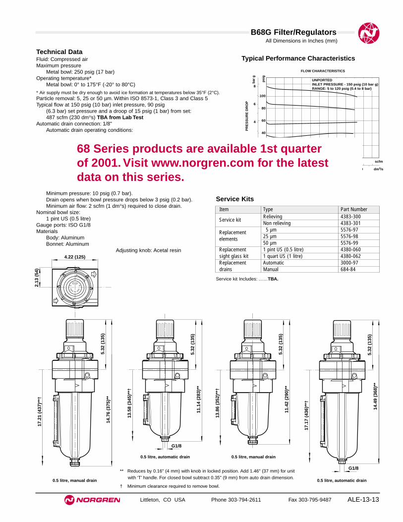
B68G Filter/Regulators
Littleton, CO USA Phone 303-794-2611 Fax 303-795-9487 ALE-13-13
All Dimensions in Inches (mm)
Technical DataFluid: Compressed airMaximum pressure
Metal bowl: 250 psig (17 bar)Operating temperature*
Metal bowl: 0° to 175°F (-20° to 80°C)
* Air supply must be dry enough to avoid ice formation at temperatures below 35°F (2°C).Particle removal: 5, 25 or 50 µm. Within ISO 8573-1, Class 3 and Class 5Typical flow at 150 psig (10 bar) inlet pressure, 90 psig
(6.3 bar) set pressure and a droop of 15 psig (1 bar) from set:487 scfm (230 dm3/s) TBA from Lab Test
Automatic drain connection: 1/8"Automatic drain operating conditions:
Minimum pressure: 10 psig (0.7 bar).Drain opens when bowl pressure drops below 3 psig (0.2 bar).Minimum air flow: 2 scfm (1 dm3/s) required to close drain.
Nominal bowl size:1 pint US (0.5 litre)
Gauge ports: ISO G1/8Materials
Body: AluminumBonnet: Aluminum
Adjusting knob: Acetal resin
Typical Performance Characteristics
FLOW CHARACTERISTICS
0 50 100 150 200 250 dm3/s
AIR FLOW
0 100 200 300 400 500 scfm
PR
ES
SU
RE
DR
OP
8
6
4
2
0
bar
g
100
80
60
40
20
0
psi
g
UNPORTEDINLET PRESSURE - 150 psig (10 bar g)RANGE: 5 to 120 psig (0.4 to 8 bar)
Service Kits
Item Type Part Number
Service kitRelieving 4383-300Non relieving 4383-301
Replacement 5 µm 5576-97
elements 25 µm 5576-9850 µm 5576-99
Replacement 1 pint US (0.5 litre) 4380-060sight glass kit 1 quart US (1 litre) 4380-062Replacement Automatic 3000-97drains Manual 684-84
Service kit Includes: ……TBA.
11.1
4 (2
83)*
*
13.5
8 (3
45)*
*†
G1/8
5.32
(13
5)
11.4
2 (2
90)*
*
13.8
6 (3
52)*
*†
5.32
(13
5)
17.1
7 (4
36)*
*†
5.32
(13
5)14
.49
(368
)**
G1/8
2.13
(54
)
4.22 (125)
17.2
1 (4
37)*
*†
5.32
(13
5)14
.76
(375
)**
** Reduces by 0.16" (4 mm) with knob in locked position. Add 1.46" (37 mm) for unitwith ‘T’ handle. For closed bowl subtract 0.35" (9 mm) from auto drain dimension.
† Minimum clearance required to remove bowl.
0.5 litre, automatic drain 0.5 litre, manual drain
0.5 litre, automatic drain0.5 litre, manual drain
68 Series products are available 1st quarter of 2001. Visit www.norgren.com for the latestdata on this series.

See Section ALE-25 for Accessories
ALE-13-14 Littleton, CO USA Phone 303-794-2611 Fax 303-795-9487
B39
● Compact design
● High efficiency oil and particle removal
● Low torque, non-rising adjusting knob
● Snap action knob locks pressure setting whenpushed in
● Standard relieving models allow reduction of outletpressure even when the system is dead-ended
Miniature Series 07 Oil Removal Filter/Regulator 1/8" and 1/4" Port Sizes
ISO Symbols
Automatic DrainRelieving
Manual DrainRelieving
Automatic DrainNon Relieving
Manual DrainNon Relieving
Ordering Information. Models listed include PTF threads, transparent bowl, relieving diaphragm, gauge, automatic drain, 5 to 100 psig (0.3 to 7bar) outlet pressure adjustment range* .
Port Size Model Number Flow† scfm (dm3/s) Weight lbs (kg)1/8" B39-102-A0KA 4.0 (1.9) 0.57 (0.26)1/4" B39-202-A0KA 4.0 (1.9) 0.57 (0.26)
† Maximum flow with 90 psig (6.3 bar) inlet pressure to maintain stated oil removal performance.
Alternative Models - ★★★ ★★ ★ -3 ★B 9
Threads SubstitutePTF AISO Rc taper BISO G parallel G
Drain SubstituteAutomatic AManual M
Element SubstituteCoalescing 0
Bowl Relief Type Gauge SubstituteTransparent Relieving Without 01Transparent Relieving With 02Transparent Non-relieving Without 03Transparent Non-relieving With 23Metal Relieving Without 33Metal Relieving With 34Metal Non-relieving Without 35Metal Non-relieving With 36
Outlet Pressure Adjustment Ranges* Substitute1 to 10 psig (0.1 to 0.7 bar) A5 to 50 psig (0.3 to 3.5 bar) E5 to 100 psig (0.3 to 7 bar) K
* Do not use these units to control pressures outside of the specified ranges.
Port Size Substitute1/8" 11/4" 2

ALE-13-15
All Dimensions in Inches (mm)
B39 Oil Removal Filter/Regulator
Littleton, CO USA Phone 303-794-2611 Fax 303-795-9487
Technical DataFluid: Compressed airMaximum pressure
Transparent bowl: 150 psig (10 bar)Metal bowl: 250 psig (17 bar)
Operating temperature*Transparent bowl: -30° to 125°F (-34° to 50°C)Metal bowl: -30° to 150°F (-34° to 65°C)
* Air supply must be dry enough to avoid ice formation at temperatures below 35°F (2°C)
Particle removal: Down to 0.01 µmAir quality: Within ISO 8573-1, Class 1 (particulates) and Class 2 (oil content)Maximum remaining oil content in outlet air: 0.01 ppm at 70°F (21°C) with an inlet
concentration of 17 ppm.Maximum flow with 90 psig (6.3 bar) inlet pressure†:
4.0 scfm (1.9 dm3/s)
† Maximum flow to maintain stated oil removal performance.Nominal bowl size: 1 fluid ounce (31 ml)Gauge ports:
1/8" PTF with PTF main ports1/8" ISO Rc with ISO Rc main ports1/8" ISO Rc with ISO G main ports
Drain connection: Will fit 1/8-27 and 1/8-28 pipe threadAutomatic drain operation: Spitter type drain operates momentarily when a rapid
change in air flow occurs or when the supply pressure is reduced.Materials
Body: ZincBonnet: AcetalValve: Brass/nitrileValve seat: AcetalBowl
Transparent: PolycarbonateMetal: Zinc
Element: Synthetic fiber and polyurethane foamElastomers: Nitrile
PORT SIZE: 1/8"INLET PRESSURE: 150 psig (10 bar g)RANGE: 5 to 100 psig (0.3 to 7 bar)
FLOW CHARACTERISTICS
0 0.5 1 1.5 2 2.5 dm3/s
AIR FLOW
0 1 2 3 4 5 6 scfm
OU
TL
ET
PR
ES
SU
RE
8
6
4
2
0
bar
g
100
80
60
40
20
0
psi
g
Typical Performance Characteristics
Automatic DrainManual Drain
2.13
(54
)
1.63 (41)
1.50 (38)
1.50
(38
)
8.41
(21
4)**
1.12
(28
) 2.67
(68
)
6.44
(16
4)
1.1 (28)
8.26
(21
0)**
1.12
(28
) 2.67
(68
)
6.29
(16
0)
1.1 (28)
Panel mounting hole diameter: 1.19" (30 mm)Maximum panel thickness: 0.25" (6 mm)
** Minimum clearance to remove bowl
Service KitsItem Type Part number
Service kitRelieving models 3407-66Non relieving models 3407-65Element 4141-10
Replacement drainsManual 773-03Automatic 3654-02
Relieving and non-relieving service kits include slip ring,diaphragm, valve seat with o-ring, valve, and valve spring. Elementkit contains element, element gasket, and bowl o-ring.
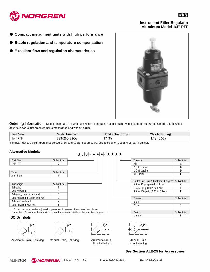
See Section ALE-25 for Accessories
Littleton, CO USA Phone 303-794-2611 Fax 303-795-9487
B38
● Compact instrument units with high performance
● Stable regulation and temperature compensation
● Excellent flow and regulation characteristics
Instrument Filter/Regulator Aluminum Model 1/4" PTF
ALE-13-16
ISO Symbols
Automatic Drain, Relieving Automatic Drain, Non Relieving
Manual Drain, Relieving Manual Drain, Non Relieving
Alternative Models
Port Size Substitute1/4” PTF 2
Type SubstituteAluminum 0
Diaphragm SubstituteRelieving 0Non relieving 1Relieving, bracket and nut 2Non relieving, bracket and nut 3Relieving with nut 4Non relieving with nut 5
Threads SubstitutePTF AISO Rc taper BISO G parallel DAPI.LP.INT K
Port Size Model Number Flow† scfm (dm3/s) Weight lbs (kg)1/4" PTF B38-200-B2CA 17 (8) 1.18 (0.53)
Ordering Information. Models listed are relieving type with PTF threads, manual drain, 25 µm element, screw adjustment, 0.6 to 30 psig
(0.04 to 2 bar) outlet pressure adjustment range and without gauge.
Outlet Pressure Adjustment Ranges* Substitute0.6 to 30 psig (0.04 to 2 bar) C1 to 60 psig (0.07 to 4 bar) F3.6 to 100 psig (0.25 to 7 bar) K
Element Substitute5 µm 125 µm 2
83B ★ ★ ★ ★ ★ ★ ★--
Drain SubstituteManual B
* Outlet pressure can be adjusted to pressures in excess of, and less than, thosespecified. Do not use these units to control pressures outside of the specified ranges.
† Typical flow 100 psig (7bar) inlet pressure, 15 psig (1 bar) set pressure, and a droop of 1 psig (0.05 bar) from set.

B38 Instrument Filter/Regulators
Littleton, CO USA Phone 303-794-2611 Fax 303-795-9487 ALE-13-17
All Dimensions in Inches (mm)
Technical DataFluid: Compressed airMaximum pressure
Manual drain: 300 psig (20 bar)Operating temperature: -40° to 175°F (-40° to 80°C) *
* Air supply must be dry enough to avoid ice formation at temperatures below 35°F (2°C).Particle removal: 5 µm or 25 µm filter elementAir quality: Within ISO 8573-1, Class 3 and Class 5 (particulates)Typical flow with 100 psig (7 bar) inlet pressure, 15 psig (1 bar) set pressure and a
droop of 1 psig (0.05 bar) from set:17 scfm (8 dm3/s)
Manual Drain Nominal bowl size:
2.4 fluid ounce (70 ml)Gauge ports:
1/4" PTF
MaterialsBody: AluminumBonnet: AluminumBowl: AluminumAdjusting screw: SteelElements
25 µm: High density polyethylene5 µm: Ceramic pyrolith
Elastomeric materials: Synthetic rubber
Typical Performance Characteristics
INLET PRESSURE - 100 psig (7 bar g)
FLOW CHARACTERISTICS - PORT SIZE: 1/4"
0 2 4 6 8 10 dm3/s
AIR FLOW
0 4 8 12 16 20 24 scfm
OU
TL
ET
PR
ES
SU
RE
4
3
2
1
0
bar
g
50
40
30
20
10
0
psi
g
REGULATION CHARACTERISTICS - PORT SIZE: 1/4"
OU
TL
ET
PR
ES
SU
RE
4
3
2
1
0
bar
g
0 2 4 6 8 bar gINLET PRESSURE
scfm dm3/s
0 20 40 60 80 100 psig
60
50
40
30
20
10
0
psi
g
7.9 3.7
3.6 1.7
5 2.4
2.5 1.2
MAXIMUM RECOMMENDEDFLOW THROUGH 1/4" PIPE10%
100%200%
100% FLOW
** Minimum clearance required to remove bowl.Panel mounting hole diameter: 1.65" (42 mm)Maximum panel thickness: 0.24" (6 mm)
0.51 (13)
2.52 (64)
2.52
(64
)
2.95
(75
)
1.26
(32
)
5.71
(19
4)
2.09
(53
)3.
11 (
79)
9.17
(23
3)**
1/8" PTF
Service KitsItem Type Part number30 psig (2 bar) range Relieving R38-100R
Non relieving R38-100NR60 and 100 psig Relieving R38-101R(4 bar and 7 bar) range Non relieving R38-101NR
Service kits includes diaphragm assembly, o-ring, valve, valvespring and 8 pan head screws.

Filter/Regulator Overview and FAQ’s
Littleton, CO USA Phone 303-794-2611 Fax 303-795-9487ALE-13-18
GENERAL PURPOSE FILTER/REGULATORKnob
Spring rest
Relief seat
Bowl
Baffle
Adjusting screw
Adjusting nut
Control spring
Diaphragm
Valve pin
Valve
Valve spring
Center post
Element
Metal bowlsight glass
Collectedcondensate
Drain
1.1 GENERAL OVERVIEW
Filter/regulators combine the features of a filter andregulator with a single compact body.
Air passes through the filter section firstremoving water and particle contaminants, and isthen regulated by the top regulator section.
See individual filter and regulator sectionsfor details.
1.2 PERFORMANCECHARACTERISTICS
The regulator section of the filter/regulatordetermines the flow and regulation characteristics ofthe unit.
Flow is therefore measured in terms ofpressure droop from set pressure (see regulators)and not flow versus pressure drop as in a filter.
Regulation characteristics are determinedin the same way as regulators.
1.3 SPECIALS
1.3.1 Can we do a Coalescing Filter/Regulator?
Yes. We have a B39 unit in the 07 Series. Othersizes could be considered for volume customers.
1.3.2 Can we do special materials?
Units are available in stainless steel (B05 and B38)for harsh environments and process applications.

Littleton, CO USA Phone 303-794-2611 Fax 303-795-9487 ALE-14-A
Section 14
ContentsLubricator Overview . . . . . . . . . . . . . . . . . . . . . . . . . . . . . . . . . . . . ALE-14-BL07 Miniature Micro-Fog® Lubricator 1/8" and 1/4" Ports . . . . . . . ALE-14-2L72 Excelon Micro-Fog and Oil-Fog Lubricator
1/4" and 3/8" Ports . . . . . . . . . . . . . . . . . . . . . . . . . . . . . . . . . . . ALE-14-4L73 Excelon Micro-Fog and Oil-Fog Lubricators
1/4", 3/8", and 1/2" Ports . . . . . . . . . . . . . . . . . . . . . . . . . . . . . . ALE-14--6L74 Excelon Micro-Fog and Oil-Fog Lubricators
3/8", 1/2", and 3/4" Ports . . . . . . . . . . . . . . . . . . . . . . . . . . . . . . . ALE-14-8L64 Olympian Plus Micro-Fog and Oil-Fog Lubricators
1/4", 3/8", 1/2", and 3/4" Ports. . . . . . . . . . . . . . . . . . . . . . . . . . ALE-14-10L68 Olympian Micro-Fog and Oil-Fog Lubricator
3/4", 1, 1-1/4", and 1-1/2" Ports . . . . . . . . . . . . . . . . . . . . . . . . . ALE-14-12L17 Micro-Fog and Oil-Fog Lubricators
3/4", 1", 1-1/4" and 1-1/2" Ports . . . . . . . . . . . . . . . . . . . . . . . . ALE-14-1410-028 Oil-Fog Lubricator 1-1/2" Port . . . . . . . . . . . . . . . . . . . . . . ALE-14-1610-076 Oil-Fog Lubricator 2" Port . . . . . . . . . . . . . . . . . . . . . . . . . ALE-14-1810-015 Micro-Fog Machine Bearing Lubricator,
8 to 32 Bearing Inch Ratings, 1/4" Port . . . . . . . . . . . . . . . . . . ALE-14-20
LubricatorsCompressed air tool lubricators areavailable in modular or inlinemodels in port sizes from 1/8" to 2".Machine bearing lubricators areavailable in 8 to 32 inch ratings.
L07 L64M/C
L68 L17 10-028 10-076 10-015
L74M/CL73M/CL72M/C
Product available1st quarter of 2001

Lubricator Overview
Littleton, CO USA Phone 303-794-2611 Fax 303-795-9487ALE-14-B
1.1 GENERAL OVERVIEW
Norgren manufactures two main types of lubricators:Oil-Fog and Micro-Fog. These units are mounteddirectly into the pipe and add small amounts of oilto the air flowing through them.
Oil Fog-Lubricators:All the oil droplets seen in the sight dome are addeddirectly into the air flow. This results in relativelylarge oil droplets passing downstream, suitable forheavy lubrication applications eg single cylindersand tools. Most competitive in line lubricators areof the Oil-Fog type.
Micro-Fog Lubricators:The oil droplets seen in the sight dome are atomizedand collected in the area above the oil in the bowl.The smaller lighter particles are drawn into the airflow and pass downstream.
As a result typically only 10% of the oilseen as drops in the sight dome is passeddownstream. The remainder falls back into the oilreservoir. Consequently, drip rate settings aresomewhat higher than their Oil-Fog equivalent. Thismakes setting much easier, particularly in low flowapplications.
The fine Micro-Fog oil particles can travellong distances through complex pipe work makingMicro-Fog lubricators suitable for multiple valveand cylinder circuits.
1.2 WHAT ARE THEDIFFERENCES BETWEENMICRO-FOG AND OIL-FOG?
1.2.1 Oil-Fog:
• Large oil particles not as fine as micro-fog.• All oil drips seen in sight domes are
delivered downstream.• For applications over short distances.• Should be mounted at same level or higher
than device being lubricated.• Standard bowls can be filled under
pressure. (Not on rapid cycle units).• Suitable for heavy lubrication applications
eg single large cylinders and tools.• Has a flow sensor which provides constant
oil output density for varying flows.
OIL-FOG LUBRICATOR
MICRO-FOG LUBRICATOR
Sightdome
Body
Flowsensor
Generatorassembly
Bowl
Syphontube
Oil
Drain(optional)
Metal bowlsight glass
Sightdome
Body
Flowsensor
Check valve
Bowl
Syphontube
Oil
Drain(optional)
Metal bowlsight glass
1.2.2 Micro-Fog:
• Small oil particles; less than 2 micron.• Only 10% of ‘drip rate’ is delivered
downstream as active lubricant (remainderis returned to main oil reservoir).
• High drip rates make drip setting easier inlow flow applications.
• Can be mounted above or below the pointof application.
• Cannot be filled without shutting offupstream air (unless a quick fill cap orremote fill device is used).
• For use with lengthy air lines, multiplevalve and cylinder circuits.
• Has a flow sensor to provide an almostconstant oil output density for varyingflows.
1.2.3 Can Oil-Fog and Micro-Fog Units beConverted?
Generally not, simply changing a green (Oil-Fog)sight dome for a red (Micro-Fog) sight dome doesnot change the function.
Some lubricators are designed around acartridge insert. In this case it may be possible toswap the cartridge and sight domes to change thefunction.

Lubricator Overview
Littleton, CO USA Phone 303-794-2611 Fax 303-795-9487 ALE-14-C
1.4 SETTING LUBRICATOR DRIP RATES
1.4.1 What is the Correct Drip Rate Setting?
The drip rate will depend on the application, theamount of lubrication required, the flow through thelubricator and the lubricator type. In Micro-Foglubricators only 10% of the droplets in the sightdome are carried downstream. The drip rate inMicro-Fog lubricators therefore tends to be muchhigher.
The following table can be used to estimatedrip rate for required flow. This is very much a ruleof thumb. In practice it is necessary to fine tune theoil drip rate in each application.
Typical Drip Rate Typical Drip Rate Approx per Minute per Minute Flow Micro-Fog Oil-Fog scfm
(dm3/s)
20 2 10 (5)40 4 20 (10)60 6 30 (15)80 8 40 (20)100 10 50 (25)120 12 60 (30)
1.3.2 Can the Drip Rate be Shut Off?
In lubricators with needle valve type sight dome,yes.
Some Norgren sight domes use a felt padwhich is soaked in oil at the point where the dropsare formed. With this type of sight dome the oildroplets cease once the felt pad dries out.
With the new style dome (L72/73/74 andL07) complete shut off is not possible. Minimumadjustment for the drip rate is around 1 drop perminute.
1.5 FILLING METHODS
1.5.1 Oil-Fog and Micro-Fog Lubricators:
The standard Oil-Fog lubricators can be filled underpressure ie without switching off the upstream air.When a fill plug is removed a check valve in thelubricator body isolates the inlet pressure from thebowl and the reservoir will depressurize. Thelubricator can then be filled with oil. When the fillplug is replaced, the reservoir will re-pressurize.
The standard Micro-Fog unit can only befilled without isolating the upstream pressure if aremote fill or quick fill nipple accessory is fitted. Toremove the fill plug of a Micro-Fog lubricator whilseunder pressure can be dangerous. If in doubt shutoff the upstream air!
1.5.2 Remote Fill Devices:
The remote oil fill system provides a means of fillingfrom a remote fill point, a single lubricator or a bankof lubricators manifolded together. The remote fillpoint may be connected to a portable reservoir or toa centralized, permanent reservoir. A portablereservoir permits the use of different lubricants indifferent groups of lubricators to suit therequirements of the machinery being lubricated. Thelubrication oil must be fed in at a higher pressurethan exists in the bowl.
The devices are NOT intended forconnection to an oil feed line which is underconstant pressure from a pump or pressurizedreservoir. The device cannot reset until the pressureis removed. Such lines are a potential safety hazardif they should leak or become broken.
1.5.3 Quick Fill Nipples:
The quick fill system is an alternative which allowsease of filling a single Micro-Fog or Oil-Foglubricator without switching off the mains air (onsome units the quick fill nipple replaces the fillerplug).
To fill the lubricator, a quick fill connectorpiped to a portable oil reservoir is snapped in placeover the quick fill nipple. The main oil reservoir cannow be pumped (or pressurized) to a pressuregreater than the lubricator bowl and the lubricatorfilled.
1.3 LUBRICATOR SIZING
Lubricators are sized by downstream flowrequirements. An analysis of air flow use must bemade. After determining how much air flow isneeded, a lubricator can be chosen. Manufacturers’curves will be like the one shown. For example, 50scfm of 90 psig lubricated air is required. Enter thecurve on the horizontal axis at the required flow.Read up to intersect the 90 psig line. Read thepressure drop on left, vertical axis as approximately2.3 psid. Pressure drop should be less than 5 psid.If pressure drop is more than 5 psid, choose a largerlubricator.
Always be sure that the lubricants in your system arecompatible with the materials in the lubricator youchoose. This is especially important for plasticlubricator reservoirs. If in doubt, check with thefactory or use a metal reservoir.
00
0 10 20 30 40 50Air Flow
Flow Characteristics
60 70 80 90 100
20 40 60 80 100 120 140 160 180 200 scfm
dm 3/s
0
.1
.2
.3
.4
.5
bar
psi
g
1
2
3
4
5
6
7
Pre
ssu
re D
rop
35 60 90 120 160 180 psig

Lubricator Overview
Littleton, CO USA Phone 303-794-2611 Fax 303-795-9487ALE-14-D
1.6 OPTIONS AND ACCESSORIES
1.6.1 Where can Liquid Level Switches beFitted?
Liquid level detection methods can be attached tothe 1 quart bowl and 2 & 5 gallon tanks.
1.6.2 Where can Remote Fill and Liquid LevelSwitches be Fitted?
The smaller bowls, L73 and up, are all capable ofeither remote fill or liquid level detection (but notboth at the same time!). The 2 quart and 2 & 5gallon tanks only can have the liquid level switchesfitted.
1.6.3 How do Liquid Level Switches Work?
Liquid level switches are bipolar reed switcheswhich change state when the float rises and falls.
Liquid level switches are normallyconnected to give an electrical signal when the floatfalls (ie when the liquid level is too low). In criticalapplications the logic could be reversed. Maximumand minimum settings are possible too.
1.7 LARGE TANKS/RESERVOIRS
1.7.1 Which Units have Large Tanks/Reservoirs?
All units in basic 1/2” and above have optionallarger bowls/tanks.
Olympian Plus and Excelon 74 are limitedto 1 quart as standard. For 2 and 5 gallon capacityuse 15/17 Series, or the 10-028/-076 (2”)lubricators.
1.8 APPLICATION SPECIFICUNITS
1.8.1 Do we Make Bearing Lubricators?
These are aerosol type lubricators. Theselubricators use air to get the oil to the point oflubrication, however the tool or application is notpowered by the air. Although produced by Norgren,systems for their application are designed and soldby Engineering and General Lubrication Systems.
1.8.2 What is a Fixed Venturi (Bi-Directional)Lubricator?
Standard Norgren lubricators use a flow sensor toachieve constant oil density with varying flows. Insome applications high flow is more important thanconstant density and a fixed venturi can be usedinstead of a flow sensor. It may also be useful insystems with rapid cycling. Consult Air Line formore details.
1.9 OILS
1.9.1 What Oils are Recommended?
Recommended oils fall into 2 categories:-1 Oils recommended for use with all Norgren
units (valves, cylinders, fittings and FRL’s).2 Oils which can be used with Norgren
lubricators but not necessarily with otherNorgren equipment.
Refer to ALE-29-2 for recommended lubricants.
1.9.2 Can Non-Recommended Oils be Used?
Some oils can be tested for suitability, but Norgrencannot be responsible for use of non-recommendedlubricants.

Lubricators Overview
Littleton, CO USA Phone 303-794-2611 Fax 303-795-9487 ALE-14-E
Problem
No Drip Rate
Oil Foaming
Oil Emulsified
Drip Rate changes after setting
Possible Cause
Oil adjustment knob fully clockwise.
Low oil level.
Airflow through lubricator too low.
Blocked oil filter screen.
Air leaks.
Over aeration.
Water in lubricator.
Fade.
Remedy
Readjust knob.
Check oil level.
Use smaller size lubricator.
Remove bowl and sight feed adjustment dome andclear syphon tube.
Remove sight feed adjustment dome and clean orreplace screen located in dome assembly.
Check bowl, filler plug and sight dome seals.Tighten if necessary.
Check bowl seals for slight leaks.
Fit filter immediately upstream.
Readjust drip rate.
1.10 SIMPLE LUBRICATOR TROUBLESHOOTING

See Section ALE-25 for Accessories
Littleton, CO USA Phone 303-794-2611 Fax 303-795-9487
L07
● Compact design
● Provides air line lubrication to one or more air driventools or other devices
● Nearly constant oil density output with varying airflow
● All around (360°) visibility of the sight-feed domesimplifies installation and adjustment
● Screw-on bowl reduces maintenance time
● Can be disassembled without the use of tools orremoval from the air line
Miniature Series 07 Micro-Fog Lubricator 1/8" and 1/4" Port Sizes
ALE-14-2
ISO Symbols
No drain Manual drain
Port Size Model Numbers Flow scfm (dm3/s)* Weight lbs (kg)1/8" L07-100-MPAA 10 (5.0 dm3/s) 0.28 (0.13)1/4" L07-200-MPAA 14 (6.7 dm3/s) 0.28 (0.13)
Ordering Information. Models listed include PTF threads and transparent bowl with manual drain.
* Approximate flow at 90 psig (6.3 bar) inlet pressure and 7 psig (0.5 bar) pressure drop.
Alternative Models
Port Size Substitute1/8" 11/4" 2
Threads SubstitutePTF AISO Rc taper BISO G parallel G
Option SubstituteNot applicable 0
Bowl and Drain SubstituteTransparent without drain QMetal with drain MTransparent with drain AOption Substitute
Not applicable 0Flow SubstituteUnidirection P
Lubricator Type SubstituteMicro-Fog M
- ★PM ★★ ★ -0 ★L 7

L07 Lubricators
Littleton, CO USA Phone 303-794-2611 Fax 303-795-9487 ALE-14-3
All Dimensions in Inches (mm)
Technical DataFluid: Compressed airMaximum pressure
Transparent bowl: 150 psig (10 bar)Metal bowl: 250 psig (17 bar)
Operating temperature*Transparent bowl: 0° to 125°F (-20° to 50°C)Metal bowl: 0° to 175°F (-20° to 80°C)
* Air supply must be dry enough to avoid ice formation at temperatures below 35°F (2°C)
Start point (i.e. minimum flow required for lubricator operation): 0.5 scfm (0.24 dm3/s) at 90 psig (6.3 bar) inlet pressure
Typical flow at 90 psig (6.3 bar) inlet pressure at 7 psig (0.5 bar) pressure drop:1/8" ports: 10 scfm (5 dm3/s) 1/4" ports: 14 scfm (6.7 dm3/s)
Nominal bowl size: 1 fluid ounce (31 ml)Drain connection: Will fit 1/8-27 and 1/8-28 pipe threadRecommended lubricants: See Section ALE-29.Materials
Body: ZincBowl
Transparent: PolycarbonateMetal: Zinc
Sight-feed dome: Transparent nylonElastomers: Neoprene & nitrile
Typical Performance Characteristics
PORT SIZE: 1/4"
INLET PRESSURE: psig (bar g)
FLOW CHARACTERISTICS
0 2 4 6 8 10 dm3/s
AIR FLOW
0 4 8 12 16 20 24 scfm
PR
ES
SU
RE
DR
OO
P
0.8
0.6
0.4
0.2
0
bar
d
10
8
6
4
2
0
psi
d
36(2.5)
23(1.6)
91(6.3)
58(4.0)
150(10)
116(8)
1.63 (41)
1.45
(37
)
7.21
(18
3)†
0.38
(10
)
1.65
(42
)
4.72
(12
0)
Manua Drain
Without Drain
7.60
(19
3)†
0.38
(10
)
1.65
(42
)
5.12
(13
0)
† Minimum clearance to remove bowl.
Service KitsItem Type Part numberService kit Seal and o-ring 3795-03Replacement drain Manual 773-03
Service kit includes o-ring, seal, and bowl o-ring.
Panel mounting hole diameter: 1.9" (30 mm)Maximum panel thickness: 0.25” (6 mm)

See Section ALE-25 for Accessories
Littleton, CO USA Phone 303-794-2611 Fax 303-795-9487
L72M, L72C
● Excelon design allows in-line or modular installation
● Quick release bayonet bowl
● Flow sensor provides a consistent oil/air ratio over awide range of flows
● Highly visible, prismatic liquid level indicator lens onmetal bowls
● All round (360°) visibility of sight-feed dome for easeof drip rate setting
● Modular installations with Excelon 72, 73, and 74series can be made to suit particular applications
Use Micro-Fog models in applications with one or more points oflubrication.
Use Oil-Fog models to lubricate a single tool, cylinder or other airdriven device.
Excelon 72 Micro-Fog and Oil-Fog Lubricator 1/4", 3/8" Port Sizes
ALE-14-4
Alternative Models L 7 2 -★ ★ ★ - ★P ★ ★
Type SubstituteOil-Fog CMicro-Fog M
Threads SubstitutePTF AISO Rc taper BISO G parallel G
Port Size Substitute1/4" 23/8" 3
Options SubstituteNone NPyrex dome P†
Drain SubstituteClosed bottom bowl E1/4 turn manual Q
† For use with metal bowl with Pyrex sight glass
Bowl SubstituteShort metal with plastic liquid level indicator DShort metal with Pyrex liquid level indicator RLong metal with plastic liquid level indicator ELong metal with Pyrex liquid level indicator UShort transparent without guard TLong transparent without guard LLong transparent with guard W
Ordering Information. Models listed include PTF threads, manual drain, and long transparent bowl without guard.
* Typical flow with 90 psig (6.3 bar) inlet pressure and a pressure drop of 7 psig (0.5 bar).
Type Main Port Size Model Number Flow* scfm (dm3/s) Weight lb (kg)†
Micro-Fog 1/4" L72M-2AP-QLN 51 (24) 1.1 (0.49)3/8" L72M-3AP-QLN 51 (24) 1.1 (0.49)
Oil-Fog 1/4" L72C-2AP-QLN 51 (24) 1.1 (0.49)3/8" L72C-3AP-QLN 51 (24) 1.1 (0.49)

L72M/C Lubricators
Littleton, CO USA Phone 303-794-2611 Fax 303-795-9487 ALE-14-5
All Dimensions in Inches (mm)
Technical DataFluid: Compressed airMaximum pressure:
Transparent bowl: 150 psig (10 bar)Metal bowl: 250 psig (17 bar)
Operating temperature*:Transparent bowl: 0° to 125°F (-20° to 50°C)Metal bowl: 0° to 150°F (-20° to 65°C)
* Air supply must be dry enough to avoid ice formation at temperatures below 35°F (2°C).
Start point (i.e. minimum flow required for lubricator operation) at 90 psig (6.3 bar)inlet pressure:Micro-Fog: 2.0 scfm (0.94 dm3/s)Oil-Fog: 1.0 scfm (0.47 dm3/s)
Typical flow at 90 psig (6.3 bar) inlet pressure and 7 psig (0.5 bar) pressure drop: 51 scfm (24 dm3/s)
Nominal reservoir capacity:Short bowl: 1.9 fluid ounce (56 ml)Long bowl: 2.2 fluid ounce (65 ml)
Manual drain connection: Will fit 1/8-27 and 1/8-28 pipe threadRecommended lubricants: See Section ALE-29.Materials:
Body: ZincReservoir:
Transparent: PolycarbonateGuard for transparent reservoir: ZincMetal: Zinc
Metal reservoir liquid level indicator lens:Transparent nylon
Sight-feed dome: Transparent nylonElastomers: Neoprene, nitrile, and Geolast®
Typical Performance Characteristics
INLET PRESSURE: psig (bar g)
FLOW CHARACTERISTICS
0 5 10 15 20 25 dm3/s
AIR FLOW
0 10 20 30 40 50 60 scfm
PR
ES
SU
RE
DR
OP
0.8
0.6
0.4
0.2
0
bar
d
10
8
6
4
2
0
psi
d
PORT SIZE 1/4"
36(2.5)
58(4.0)
91(6.3)
116(8.0)
150(10.0)
Short Bowl with 1/4 Turn Manual Drain
Long Bowl with Closed Bottom
Oil-FogMicro-Fog
1.98 (50)
1.91
(48
)
Short Bowl with Closed Bottom
Long Bowl with 1/4 Turn Manual Drain
5.27
(13
4)
8.58
(21
8)**
1.63
(41
)
2.51
(64
) †
0.75
(19
)
5.83
(14
8)
9.13
(23
2)**
4.49
(11
4)
7.79
(19
8)**
5.04
(12
8)
8.35
(21
2)**
** Minimum clearance required to remove bowl.
† Optional pyrex sight-feed dome.
Service KitsItem Type Part NumberService kit Seal and gasket 4382-500Liquid level lens kit Prismatic 4380-030Replacement drains 1/4 turn manual 619-50
Service kit includes plug o-ring, sight-feed dome seal, manual drain o-ring and bowl o-ring.

See Section ALE-25 for Accessories
Littleton, CO USA Phone 303-794-2611 Fax 303-795-9487
L73M, L73C
● Excelon design allows in-line or modular installation
● Quick release bayonet bowl
● Flow sensor design provides a nearly constant oil/airratio over a wide range of air flows
● Highly visible, prismatic liquid level indicator lens
● All around (360°) visibility of the sight-feed domesimplifies installation and adjustment
● Modular installations with Excelon 72, 73, and 74series can be made to suit particular applications
Use Micro-Fog models in applications containing one or morepoints of lubrication.Use Oil-Fog models to lubricate a single tool, cylinder, or other airdriven device.
Excelon 73 Micro-Fog and Oil-FogLubricators 1/4", 3/8", 1/2" Port Sizes
ALE-14-6
Alternative Models
Ordering Information. Models listed include PTF threads, manual drain, and metal bowl with plastic liquid level indicator.
* Maximum recommended air flow. Higher flows create excessive air velocity, turbulence, and pressure losses.
Type Main Port Size Model Number Flow* scfm (dm3/s) Weight lb (kg)
Micro-Fog1/4" L73M-2AP-QDN 60 (28) 1.1 (0.50)3/8" L73M-3AP-QDN 60 (28) 1.1 (0.50)1/2" L73M-4AP-QDN 60 (28) 1.1 (0.50)
Oil-Fog1/4" L73C-2AP-QDN 60 (28) 1.1 (0.50)3/8" L73C-3AP-QDN 60 (28) 1.1 (0.50)1/2" L73C-4AP-QDN 60 (28) 1.1 (0.50)
L 7 3 -★ ★ ★ - ★★ ★ ★
Threads SubstitutePTF AISO Rc taper BISO G parallel G
Air Flow Direction SubstituteUni-directional P
Options SubstituteNone NPyrex sight-feed dome † PQuick fill nipple Q
Type SubstituteOil-Fog CMicro-Fog M
Bowl SubstituteMetal with plastic liquid level indicator DTransparent with guard PMetal with Pyrex liquid level indicator† RTransparent T
Drain SubstituteClosed bottom EManual 1/4 turn Q
Port Size Substitute1/4" 23/8" 31/2" 4
† Order optional Pyrex sight-feed dome when ordering metal bowl with Pyrex liquid level indicator.

L73M/C Lubricators
Littleton, CO USA Phone 303-794-2611 Fax 303-795-9487 ALE-14-7
All Dimensions in Inches (mm)
Technical DataFluid: Compressed airMaximum pressure
Transparent bowl: 150 psig (10 bar)Metal bowl: 250 psig (17 bar)
Operating temperature*Transparent bowl: 0° to 125°F ( -20° to 50°C)Metal bowl: 0° to 175°F (-20° to 80°C)
* Air supply must be dry enough to avoid ice formation at temperatures below 35°F (2°C).Start point (minimum flow required for lubricator operation): 1.5 scfm (0.71 dm
3/s)
at 90 psig (6.3 bar) inlet pressureTypical flow with 90 psig (6.3 bar) inlet pressure and 3.5 psig (0.25 bar) pressure
drop: 80 scfm (38 dm3/s)
Maximum recommended flow: 60 scfm (28 dm3/s). Air flows above 60 scfm
(28 dm3/s) create excessive air velocity, turbulence, and pressure losses. In
addition, the fog produced by the lubricator will wet out on the pipe walls and willnot be carried by the compressed air to the point of application.
Nominal bowl size: 3.5 fluid ounce (0.1 liter)Manual drain connection: Will fit 1/8-27 and 1/8-28 pipe threadRecommended lubricants: See Section ALE-29.Materials
Body: AluminumBowl
Transparent: PolycarbonateTransparent with guard: Polycarbonate, steel guardMetal: AluminumMetal bowl liquid level indicator lens: Transparent nylon
Sight-Feed dome: Transparent nylonElastomers: Neoprene and nitrile
PR
ES
SU
RE
DR
OP 0.3
0.2
0.1
0
bar
d
5
4
3
2
1
0
psi
d
PORT SIZE: 3/8"
0 10 20 30 40 50 dm3/s
0 20 40 60 80 100 scfm
MICRO-FOG FLOW CHARACTERISTICS
150 (10.0)116 (8.0)90 (6.3)
58 (4.0)
INLET PRESSURE:psig (bar)36 (2.5)
PR
ES
SU
RE
DR
OP 0.3
0.2
0.1
0
bar
d
5
4
3
2
1
0
psi
d
PORT SIZE: 3/8"
0 10 20 30 40 50 dm3/s
AIR FLOW
0 20 40 60 80 100 scfm
AIR FLOWOIL-FOG FLOW CHARACTERISTICS
150 (10.0)116 (8.0)90 (6.3)
58 (4.0)
36 (2.5)
INLET PRESSURE:psig (bar)
Typical Performance Characteristics
10.0
4 (2
55)
Wit
h D
rain
†
2.68 (68)
2.45
(62
)1.22
(31
)
2.74
(70
) **
1.87
(47
)
1.00
(25
)
5.38
(13
7) C
lose
d B
ott
om
6.15
(15
6) W
ith
Dra
in
9.29
(23
6) C
lose
d B
ott
om
†
Service kit includes dome seal, drain seal, bowl seal and fill plugseal.
Service KitsItem Type Part NumberService kit Seal & Gasket 4382-600Liquid level lens kit Prismatic 4380-020Replacement drain Manual 1/4 turn 619-50
** Optional pyrex sight-feed dome.
† Minimum clearance to remove bowl.

Littleton, CO USA Phone 303-794-2611 Fax 303-795-9487
L74M, L74C
● Excelon design allows in-line or modular installation
● Quick release bayonet bowl
● Highly visible, prismatic liquid level indicator lens
● Flow sensor design provides a nearly constant oil/airratio over a wide range of air flows
● All around (360°) visibility of the sight-feed domesimplifies installation and adjustment
● Modular installations with Excelon 72, 73, and 74series can be made to suit particular applications
Use Micro-Fog models in applications with one or more points oflubrication.Use Oil-Fog models to lubricate a single tool, cylinder, or other airdriven device.
Excelon 74 Micro-Fog and Oil-Fog Lubricators 3/8", 1/2", 3/4" Port Sizes
ALE-14-8
Alternative Models L 7 4 -★ ★ ★ - ★★ ★ ★
Threads SubstitutePTF AISO Rc taper BISO G parallel G
Air Flow Direction SubstituteBi-directional (Oil-Fog only) EUni-directional P
Options SubstituteLow oil level switch *** LNone NPyrex dome *† PQuick fill nipple Q
Type SubstituteOil-Fog CMicro-Fog M
Bowl Substitute1 quart US (1 liter) metal with Pyrex liquid level indicator †† A
7 fluid oz. (0.2 liter) metal with plastic liquid level indicator D
7 fluid oz. (0.2 liter) transparent with guard P
7 fluid oz. (0.2 liter) metal with Pyrex liquid level indicator†† R
Drain SubstituteClosed bottom EManual 1/4 turn QRemote fill device - Use onlywith 7 fluid oz. (0.2 liter) bowl. R
Port Size Substitute3/8" 31/2" 43/4" 6
*** Low oil level switch requires 1 litre bowl, type ‘A’ at 9th digit.*† Pyrex dome used only with bowl type ‘A’ or ‘R’ at 9th digit.†† Pyrex liquid level indicator used only with option ‘P’ at 10th digit.
Ordering Information. Models listed include PTF threads, manual drain, and 7 fluid ounce (0.2 liter) metal bowl with plastic liquid level indicator.
* Models listed in the order table must not be located downstream of frequently cycling directional control valves. Order the optional bi-directional Oil-Fog Lubricatorfor use under such conditions.
** Typical flow with 90 psig (6.3 bar) inlet pressure and a pressure drop of 7 psig (0.5 bar).† Lubricators with 1 quart (1 litre) metal bowl: Add 2.01 lbs (0.91 kg).
Type Main Port Size Model Number * Flow** scfm (dm3/s) Weight lb (kg)†
Micro-Fog3/8" L74M-3AP-QDN 114 (54) 1.70 (0.77)1/2" L74M-4AP-QDN 154 (73) 1.61 (0.73)3/4" L74M-6AP-QDN 142 (67) 1.55 (0.71)
Oil-Fog3/8" L74C-3AP-QDN 118 (56) 1.70 (0.77)1/2" L74C-4AP-QDN 192 (91) 1.61 (0.73)3/4" L74C-6AP-QDN 186 (88) 1.55 (0.71)

See Section ALE-25 for Accessories
L74M/C Lubricators
Littleton, CO USA Phone 303-794-2611 Fax 303-795-9487 ALE-14-9
All Dimensions in Inches (mm)
Technical DataFluid: Compressed airMaximum pressure:
Transparent bowl: 150 psig (10 bar)Metal bowl: 250 psig (17 bar)
Operating temperature*:Transparent bowl: 0° to 125°F (-20° to 50°C)Metal bowl: 0° to 175°F (-20° to 80°C)
* Air supply must be dry enough to avoid ice formation at temperatures below 35°F (2°C).Start point (i.e. minimum flow required for lubricator operation): 2.5 scfm
(0.94 dm3/s) at 90 psig (6.3 bar) inlet pressureTypical flow with 90 psig (6.3 bar) inlet pressure and 7 psig (0.5 bar) pressure drop
Micro-fog: 154 scfm (73 dm3/s)
Oil-fog: 92 scfm (91 dm3/s)
Nominal bowl size:Standard: 7 fluid ounce (0.2 liter)Optional: 1 quart US (1 liter)
Manual drain connection: Will fit 1/8-27 and 1/8-28 pipe threadRecommended lubricants: See Section ALE-29.Materials
Body: AluminumBowl
Transparent: Polycarbonate with steel bowl guardMetal: Aluminum
Metal bowl liquid level indicator lens:7 fluid ounce (0.2 liter): Transparent nylon1 quart US (1 liter): Pyrex
Sight-feed dome: Transparent nylon Elastomers: Neoprene and Nitrile
ISO Symbols
No Drain With Drain
0.6
0.4
0.2
0
PR
ES
SU
RE
DR
OP
bar
d
10
8
6
4
2
0
psi
d MICRO-FOGPORT SIZE: 1/2"
36(2.5)
58(4.0)
150(10.0)
90(6.3)
116(8.0)
INLET PRESSURE: psig (bar)
0 20 40 60 80 100 dm3/s
AIR FLOW
0 40 80 120 160 200 scfm
FLOW CHARACTERISTICS
0.6
0.4
0.2
0
PR
ES
SU
RE
DR
OP
bar
d
10
8
6
4
2
0 p
sid
OIL-FOGPORT SIZE: 1/2"
36(2.5)
58(4.0)
150(10.0)
90(6.3)
116(8.0)
INLET PRESSURE: psig (bar)
0 20 40 60 80 100 dm3/s
AIR FLOW
0 40 80 120 160 200 scfm
FLOW CHARACTERISTICS
Typical Performance Characteristics
2.40 (61)
4.32 (110)
3.15 (80)
11.1
4 (2
83)
Clo
sed
Bo
tto
m
1.00
(25
)
1.86
(47
)
20.0
0 (5
08)
†
2.89
(74
)1.
00 (
25)
1.45
(37
) 3.15 (80)
6.18
(15
7) C
lose
d B
ott
om
1.86
(47
)
10.8
7 (2
76)
†
6.95
(17
7) W
ith
Dra
in
11.9
3 (3
03)
Wit
h D
rain2.
69 (
68)*
*
** Optional pyrex sight-feed dome.† Minimum clearance required to remove bowl.
2.69
(68
)**
Service kit includes dome seal, drain seal, bowl seal andfill plug seal
Service KitsItem Type Part NumberService kit Seal & Gasket 4382-700
Liquid level lens kit7 fluid ounce (0.2 liter) bowl 4380-0501 quart US (1 liter) bowl 2273-22
Replacement drain Manual 1/4 turn 619-50

See Section ALE-25 for Accessories
Littleton, CO USA Phone 303-794-2611 Fax 303-795-9487
L64M, L64C
● Olympian Plus plug in design
● Constant oil density output with varying flow
● Easy fill with quick release bayonet bowl
● High visibility prismatic sight glass
Use Micro-Fog models in applications with one or more points oflubrication.Use Oil-Fog models to lubricate a single tool, cylinder or other airdriven device.
Olympian Plus Micro-Fog and Oil-Fog Lubricators 1/4", 3/8", 1/2", 3/4" Port Sizes
ALE-14-10
ISO Symbol
Ordering Information. Models listed include PTF threads and 7 fluid ounce (0.2 liter) metal reservoir with drain.
Type Port Size Model Weight lb ( kg)1/4" L64M-2AP-QDN 3.13 (1.42)
Micro-Fog 3/8" L64M-3AP-QDN 3.09 (1.40)1/2" L64M-4AP-QDN 3.02 (1.37)3/4" L64M-6AP-QDN 3.81 (1.73)
L 6 4 -★ ★ ★ - ★P ★ ★
Type SubstituteOil-Fog CMicro-Fog M
Threads SubstitutePTF AISO Rc taper BISO G parallel GNo yoke N
Port Size Substitute1/4" 23/8" 31/2" 43/4" 6No yoke N
Options SubstituteNone NQuick fill device Q
Bowl Substitute7 oz.Metal with liquid level indicator D7 oz. Transparent with guard P1 qt. metal with pyrex liquid level Aindicator
Drain SubstituteClosed bottom bowl EManual 1/4 turn QRemote fill device RUse only with 7 oz. (0.2 liter) bowl.
Alternative Models

L64M/C Lubricators
Littleton, CO USA Phone 303-794-2611 Fax 303-795-9487 ALE-14-11
Technical DataFluid: Compressed airMaximum pressure:
Guarded transparent bowl: 150 psig (10 bar)Metal bowll: 250 psig (17 bar)
Operating temperature*Guarded transparent bowl: 0° to 125°F (-20° to 50°C)Metal bowl: 0° to 175°F (-20° to 80°C)
* Air supply must be dry enough to avoid ice formation at temperatures below 35°F (2°C).
Start point (i.e. minimum flow required for lubricator operation) at 90 psig (6.3 bar)inlet pressureMicro-Fog: 3.2 scfm (1.5 dm3/s)Oil-Fog: 3.2 scfm (1.5 dm3/s)
Typical flow at 90 psig (6.3 bar) inlet pressure and 7 psig (0.5 bar) pressure drop:153 scfm (72 dm3/s)
Nominal bowl capacityTransparent bowl without guard: 7 fluid ounce (0.2 liter)Metal bowl: 7 fluid ounce (0.2 liter) standard, 1 quart US (1 liter) optional
Manual drain connection: Will fit 1/8-27 and 1/8-28 pipe threadRecommended lubricants: See Section ALE-29.Materials
Body: ZincYoke: ZincMetal bowl: AluminiumStandard metal bowl prismatic liquid level indicator lens: GrilamidOptional metal bowl sight glass [standard on 1 quart (1 liter bowl)]: PyrexOptional transparent bowl: Polycarbonate
Sight-feed dome: PolycarbonateElastomeric materials: Synthetic rubber
Typical Performance Characteristics
INLET PRESSURE: psig (bar g)
FLOW CHARACTERISTICS
0 20 40 60 80 100 dm3/s
AIR FLOW
0 40 80 120 160 200 240 scfm
PR
ES
SU
RE
DR
OP
0.8
0.6
0.4
0.2
0
bar
d
10
8
6
4
2
0
psi
d
PORT SIZE 1/2"
36(2.5)
58(4.0)
91(6.3)
116(8.0)
150(10.0)
9.53
(24
2)
10.1
6 (2
58)†
2.48
(63
)
4.13 (105)**
1.46
(37
)
2.91
(74
)
** 6.18" (157) for models with 3/4" ports.† Minimum clearance required to remove unit.
4.13 (105)**
4.33 (110)
2.76
(70
)
1.46
(37)
2.91
(74
)
4.92
(12
5)
2.48
(63
)
14.4
1 (3
66)
15.6
7 (3
98)†
OPTIONAL1-QUART(1-LITER)BOWL
Standard 7 fluid ounce (0.2 liter) bowl
Optional 1 quart US (1 liter) bowl
Service KitsItem Type Part NumberService kit All models 4382-200
Prismatic (standard) 4380-042Replacement sight glass7 fluid oz. (0.2 liter bowl)
Pyrex (optional) 4380-041
Replacement sight glassPyrex 2273-22
1 quart US (1 liter)Service kit includes all seals, flow sensor, eyelet, dome screen, balland spring.
All Dimensions in Inches (mm)
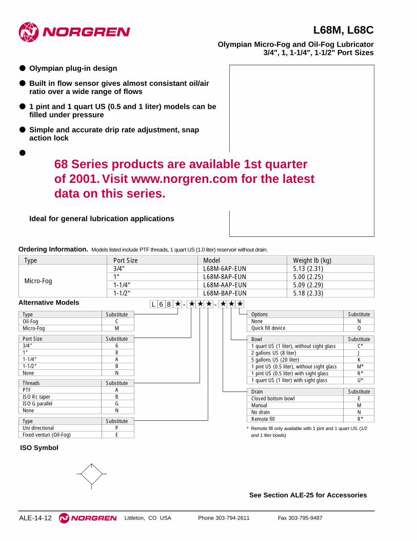
See Section ALE-25 for Accessories
ALE-14-12
Alternative Models
Ordering Information. Models listed include PTF threads, 1 quart US (1.0 liter) reservoir without drain.
Type Port Size Model Weight lb (kg)3/4" L68M-6AP-EUN 5.13 (2.31)
Micro-Fog 1" L68M-8AP-EUN 5.00 (2.25)1-1/4" L68M-AAP-EUN 5.09 (2.29)1-1/2" L68M-BAP-EUN 5.18 (2.33)
L 6 8 -★ ★ ★ - ★★ ★ ★
Type SubstituteOil-Fog CMicro-Fog M
Threads SubstitutePTF AISO Rc taper BISO G parallel GNone N
Type SubstituteUni directional PFixed venturi (Oil-Fog) E
Port Size Substitute3/4" 61" 81-1/4" A1-1/2" BNone N
Options SubstituteNone NQuick fill device Q
Drain SubstituteClosed bottom bowl EManual MNo drain NRemote fill R*
Bowl Substitute1 quart US (1 liter), without sight glass C*2 gallons US (8 liter) J5 gallons US (20 liter) K1 pint US (0.5 liter), without sight glass M*1 pint US (0.5 liter) with sight glass R*1 quart US (1 liter) with sight glass U*
* Remote fill only available with 1 pint and 1 quart US. (1/2and 1 liter bowls)
Littleton, CO USA Phone 303-794-2611 Fax 303-795-9487
L68M, L68C
● Olympian plug-in design
● Built in flow sensor gives almost consistant oil/airratio over a wide range of flows
● 1 pint and 1 quart US (0.5 and 1 liter) models can befilled under pressure
● Simple and accurate drip rate adjustment, snapaction lock
●
Ideal for general lubrication applications
Olympian Micro-Fog and Oil-Fog Lubricator3/4", 1, 1-1/4", 1-1/2" Port Sizes
ISO Symbol
68 Series products are available 1st quarter of 2001. Visit www.norgren.com for the latestdata on this series.

L68M/C Lubricators
ALE-14-13
All Dimensions in Inches (mm)
Littleton, CO USA Phone 303-794-2611 Fax 303-795-9487
INLET PRESSURE: psig (bar g)
FLOW CHARACTERISTICS
0 40 80 120 160 200 dm3/s
AIR FLOW
0 80 160 240 320 400 480 scfm
0.8
0.6
0.4
0.2
0
PR
ES
SU
RE
DR
OP
bar
g
10
8
6
4
2
0
psi
g
MICRO FOGUNPORTED
36(2.5)
58(4.0)
91(6.3)
116(8.0)
150(10.0)
INLET PRESSURE: psig (bar g)
FLOW CHARACTERISTICS
0 100 200 300 400 500 dm3/s
AIR FLOW
0 200 400 600 800 1 000 scfm
0.8
0.6
0.4
0.2
0
PR
ES
SU
RE
DR
OP
bar
g
10
8
6
4
2
0
psi
g
FIXED VENTURIPORT SIZE 1-1/2"
36(2.5)
58(4.0)
91(6.3)
116(8.0)
150(10.0)
INLET PRESSURE: psig (bar g)
FLOW CHARACTERISTICS
0 40 80 120 160 200 dm3/s
AIR FLOW
0 80 160 240 320 400 480 scfm
0.8
0.6
0.4
0.2
0
PR
ES
SU
RE
DR
OP
bar
g
10
8
6
4
2
0
psi
g
OIL FOGUNPORTED
36(2.5)
58(4.0)
91(6.3)
116(8.0)
150(10.0)
Typical Performance CharacteristicsTechnical DataFluid: Compressed airMaximum pressure: 250 psig (17 bar)Operating temperature*: 0° to 175°F (-20° to 80°C)
* Air supply must be dry enough to avoid ice formation at temperatures below 35°F (2°C).Start point (i.e. minimum flow required for lubricator operation) at 90 psig (6.3 bar)
inlet pressure:Micro-Fog: 13 scfm (6 dm3/s)Oil-Fog: 13 scfm (6 dm3/s) Fixed venturi: 110 scfm (52 dm3/s)
Typical flow at 90 psig (6.3 bar) inlet pressure and 7 psig (0.5 bar) pressure drop:Micro-Fog and Oil-Fog: 370 scfm (175 dm3/s)Fixed venturi: 848 scfm (400 dm3/s)
Nominal bowl sizes:1 pint US (0.5 liter)
1 quart US (1 liter)2 gallons US (8 liter)
2.13
(54
)
4.92 (125)
1 q
uar
t 12
.1 (
1 lit
er 3
08)*
*†
1 q
uar
t 1
0.41
(lit
er 2
65)*
*†
2.91
(74
)
1 p
int
2.59
(.5
lite
r 24
4)**
†
1 p
int
8.72
(.5
lite
r 22
2)**
†
** For manual drain add 0.32" (8 mm) on0.5 and 1 liter bowls.
† Minimum clearance required to removebowl.
1 liter
Service KitsItem Type Part Number
Service kitMicro-Fog 4382-301Oil-Fog 4382-300
Replacement 1 pint US (0.5 liter) 4380-060sight glass 1 quart US (1 liter) 4380-062Replacement drain Manual 684-84
Service kit includes sight dome assembly, screen, filler plug, ball,threaded cap and necessary seals and o-rings. Oil-Fog service kitalso contains spring.TBA.
68 Series products are available 1st quarter of 2001. Visit www.norgren.com for the latestdata on this series.
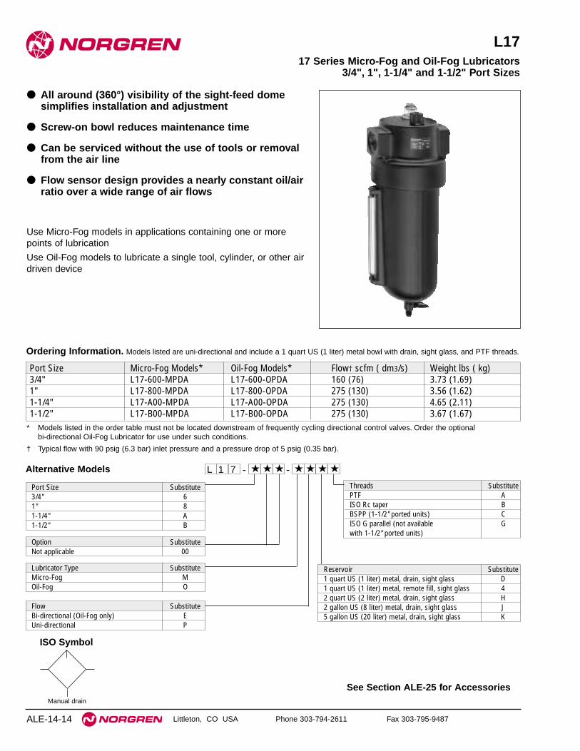
See Section ALE-25 for Accessories
Littleton, CO USA Phone 303-794-2611 Fax 303-795-9487
L17
● All around (360°) visibility of the sight-feed domesimplifies installation and adjustment
● Screw-on bowl reduces maintenance time
● Can be serviced without the use of tools or removalfrom the air line
● Flow sensor design provides a nearly constant oil/airratio over a wide range of air flows
Use Micro-Fog models in applications containing one or morepoints of lubrication
Use Oil-Fog models to lubricate a single tool, cylinder, or other airdriven device
17 Series Micro-Fog and Oil-Fog Lubricators3/4", 1", 1-1/4" and 1-1/2" Port Sizes
ALE-14-14
ISO Symbol
Manual drain
Alternative Models - ★★★ ★★ ★ -1 ★L 7
Threads SubstitutePTF AISO Rc taper BBSPP (1-1/2" ported units) CISO G parallel (not available Gwith 1-1/2" ported units)
Reservoir Substitute1 quart US (1 liter) metal, drain, sight glass D1 quart US (1 liter) metal, remote fill, sight glass 42 quart US (2 liter) metal, drain, sight glass H2 gallon US (8 liter) metal, drain, sight glass J5 gallon US (20 liter) metal, drain, sight glass K
Lubricator Type SubstituteMicro-Fog MOil-Fog O
Port Size Substitute3/4" 61" 81-1/4" A1-1/2" B
Flow SubstituteBi-directional (Oil-Fog only) EUni-directional P
Option SubstituteNot applicable 00
Ordering Information. Models listed are uni-directional and include a 1 quart US (1 liter) metal bowl with drain, sight glass, and PTF threads.
Port Size Micro-Fog Models* Oil-Fog Models* Flow† scfm ( dm3/s) Weight lbs ( kg)3/4" L17-600-MPDA L17-600-OPDA 160 (76) 3.73 (1.69)1" L17-800-MPDA L17-800-OPDA 275 (130) 3.56 (1.62)1-1/4" L17-A00-MPDA L17-A00-OPDA 275 (130) 4.65 (2.11)1-1/2" L17-B00-MPDA L17-B00-OPDA 275 (130) 3.67 (1.67)
* Models listed in the order table must not be located downstream of frequently cycling directional control valves. Order the optional bi-directional Oil-Fog Lubricator for use under such conditions.
† Typical flow with 90 psig (6.3 bar) inlet pressure and a pressure drop of 5 psig (0.35 bar).

L17 Lubricators
Littleton, CO USA Phone 303-794-2611 Fax 303-795-9487 ALE-14-15
All Dimensions in Inches (mm)
Technical DataFluid: Compressed airMaximum pressure: 250 psig (17 bar)Operating temperature*: 0° to 175°F (-20° to 80°C)* Air supply must be dry enough to avoid ice formation at temperatures below 35°F (2°C).Start point (minimum flow required for lubricator operation): 8 scfm (3.8 dm3/s) at
90 psig (6.3 bar) inlet pressureTypical flow with 90 psig (6.3 bar) inlet pressure and 5 psig (0.35 bar) pressure
drop:1" ports: 275 scfm (130 dm3/s)
Nominal reservoir sizeStandard: 1 quart US (1 liter)Optional: 2 quart US (2 liter)
2 gallon US (8 liter)5 gallon US (20 liter)
Manual drain connection on 1 quart reservoir: Will fit 1/8-27 and 1/8-28 pipe threadRecommended lubricants: See Section ALE-29.Materials
Body: AluminumReservoir:
1 quart US (1 liter): Aluminum2 quart US (2 liter) and larger: Steel**
Reservoir sight glass: PyrexSight-feed dome
Standard: Transparent nylonOptional: Pyrex and aluminum
Elastomers: Neoprene and nitrile** The 2 and 5 gallon (8 and 20 liter) steel reservoirs are ASME rated according to
the ASME Pressure Vessel Code, Section VIII
Typical Performance Characteristics
PR
ES
SU
RE
DR
OP 0.3
0.2
0.1
0
bar
d
5
4
3
2
1
0
psi
d
0 40 80 120 160 200 dm3/s
AIR FLOW
0 80 160 240 320 400 scfm
36 (2.5 ) 58 (4.0) 90 (6.3) 116 (8.0)INLET PRESSURE:psig (bar g)
150(10.0)
180(12.5)
PORT SIZE: 1"
4.50 (114)
L17 Micro-Fog
2.40(61)
10.4
(26
5) w
ith
dra
in
4.32
(11
0)2.
03†
(52)
16.9
(42
9)††
10.0
(25
4) w
ith
ou
t d
rain
B
C
A
L17 Oil-Fog Micro-Fog shown,Typical of Oil Fog
1 quart US (1 liter) reservoir1/4 turn drain 2 quart US (2 liter) reservoir
2 gallon US (8 liter) reservoir5 gallon US (20 liter) reservoir
Reservoir A B ∅ C2 quart US (2 liter) 13.1 ( 333) 4.63 (118) 5.38 (137)2 gallon US (8 liter) 21.2 (538) 6.25 (159) 7.44 (189)5 gallon US (20 liter) 24.2 (614) 10.3 (260) 11.4 (291)† Standard dome: 2.03" (52 mm)
Pyrex dome: 2.72" (69 mm)
†† Minimum clearance required to remove bowl.
Service kit 5771-02 includes o-rings, seals and gaskets.
Reservoir sight glass kits, include all o-rings, seals, glass,guard, and sight glass hardware.
Service KitsItem Type Part NumberService kit Oil-Fog and Micro-Fog 5771-02
Reservoir sight glass kit1 quart US (1 liter) 2273-222 quart US (2 liter) 2273-042/5 gallon US (8/20 liter) 2274-01
Replacement drain 1/4 Turn 619-50

See Section ALE-25 for Accessories
Littleton, CO USA Phone 303-794-2611 Fax 303-795-9487ALE-14-16
10-028
● Designed to lubricate a single tool, valve, cylinder, airmotor, or other air driven device.
● One Oil-Fog lubricator should be provided for eachdevice requiring lubrication
● All around (360°) visibility of the sight-feed domesimplifies installation and adjustment
● Lubricators equipped with 1 and 2 quart (1 and 2 liter)reservoirs can be filled under pressure
● The 2 and 5 U.S. gallon (8 and 20 liter) reservoirs arerated to ASME Pressure Vessel Code, Section VIII
Oil-Fog Lubricator1-1/2" Port Size
ISO Symbol
With Drain
* Models with 1 and 2 quart reservoirs must not be located downstream of frequently cycling directional control valves. Models with the 2 and 5 gallon reservoirs maybe located downstream of frequently cycling directional control valves.
** At 100 psig (6.9 bar) inlet pressure and pressure drop of 5 psid (0.35 bar).
Reservoir RecommendedReservoir Working Capacity Operating Flow Range** Weight
Model Number Nominal Size Fluid Ounce (Liter) scfm (dm3/s) lbs (kg)10-028-045 1 quart (1 liter) * 19 (0.56) 110 to 590 (52 to 278) 5 (0.91)10-028-046 2 quart (2 liter) * 45 (1.33) 110 to 590 (52 to 278) 6 (2.72)10-028-047 2 U.S. gallon (8 liter) 113 (3.34) 110 to 590 (52 to 278) 16 (7.26)10-028-048 5 U.S. gallon (20 liter) 316 (9.34) 110 to 590 (52 to 278) 28 (12.70)
Ordering Information. Models listed have 1-1/2" PTF parallel threads.
Alternative Models 2★- ★ ★★ ★8 - -01
Option AddFactory installed quick fill nipple -2JFactory installed sight feed dome -8W
★
Threads SubstitutePTF 0ISO G parallel 8
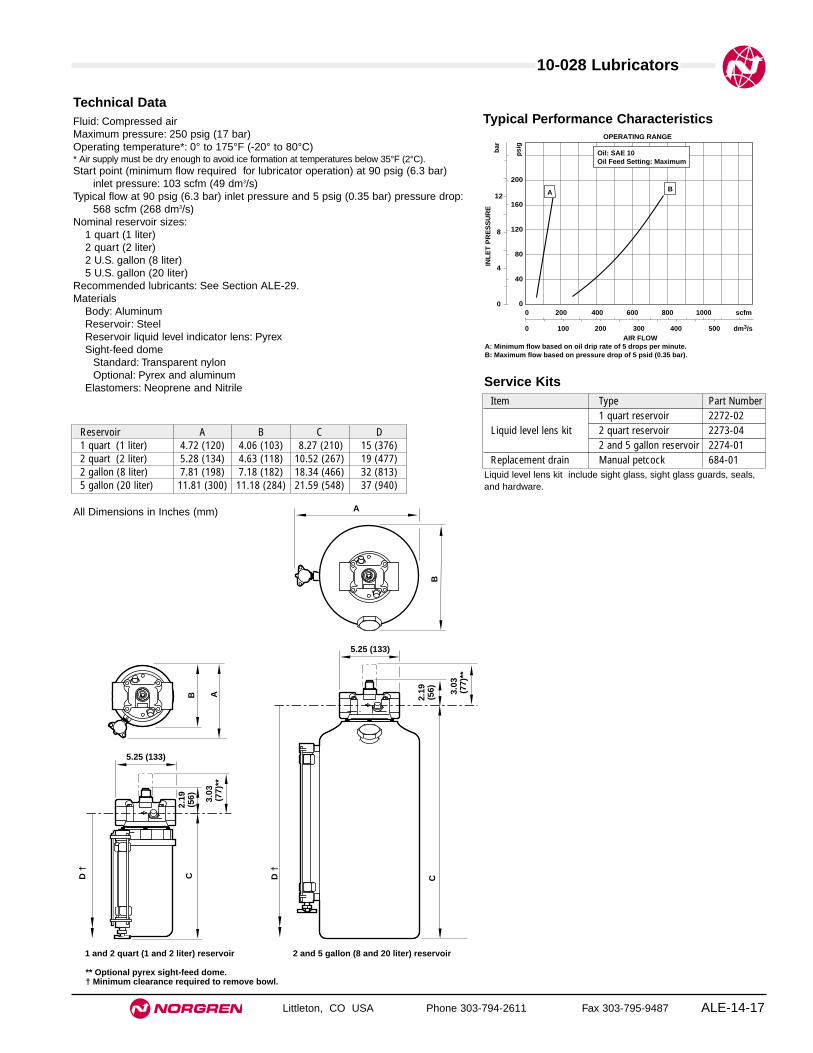
10-028 Lubricators
ALE-14-17
All Dimensions in Inches (mm)
Littleton, CO USA Phone 303-794-2611 Fax 303-795-9487
Technical DataFluid: Compressed airMaximum pressure: 250 psig (17 bar)Operating temperature*: 0° to 175°F (-20° to 80°C)* Air supply must be dry enough to avoid ice formation at temperatures below 35°F (2°C).Start point (minimum flow required for lubricator operation) at 90 psig (6.3 bar)
inlet pressure: 103 scfm (49 dm3/s) Typical flow at 90 psig (6.3 bar) inlet pressure and 5 psig (0.35 bar) pressure drop:
568 scfm (268 dm3/s)Nominal reservoir sizes:
1 quart (1 liter)2 quart (2 liter)2 U.S. gallon (8 liter)5 U.S. gallon (20 liter)
Recommended lubricants: See Section ALE-29.Materials
Body: AluminumReservoir: Steel Reservoir liquid level indicator lens: PyrexSight-feed dome
Standard: Transparent nylonOptional: Pyrex and aluminum
Elastomers: Neoprene and Nitrile
12
8
4
0
INL
ET
PR
ES
SU
RE
bar
200
160
120
80
40
0
psi
g
0 100 200 300 400 500 dm3/sAIR FLOW
0 200 400 600 800 1000 scfm
OPERATING RANGE
A B
A: Minimum flow based on oil drip rate of 5 drops per minute.B: Maximum flow based on pressure drop of 5 psid (0.35 bar).
Oil: SAE 10Oil Feed Setting: Maximum
Typical Performance Characteristics
Reservoir A B C D1 quart (1 liter) 4.72 (120) 4.06 (103) 8.27 (210) 15 (376)2 quart (2 liter) 5.28 (134) 4.63 (118) 10.52 (267) 19 (477)2 gallon (8 liter) 7.81 (198) 7.18 (182) 18.34 (466) 32 (813)5 gallon (20 liter) 11.81 (300) 11.18 (284) 21.59 (548) 37 (940)
C
5.25 (133)
2.19
(56)
1 and 2 quart (1 and 2 liter) reservoir 2 and 5 gallon (8 and 20 liter) reservoir
** Optional pyrex sight-feed dome.† Minimum clearance required to remove bowl.
5.25 (133)
2.19
(56)
CD †
D †
B A
A
B
3.03
(7
7)**
3.03
(7
7)**
Liquid level lens kit include sight glass, sight glass guards, seals,and hardware.
Service KitsItem Type Part Number
1 quart reservoir 2272-02Liquid level lens kit 2 quart reservoir 2273-04
2 and 5 gallon reservoir 2274-01Replacement drain Manual petcock 684-01
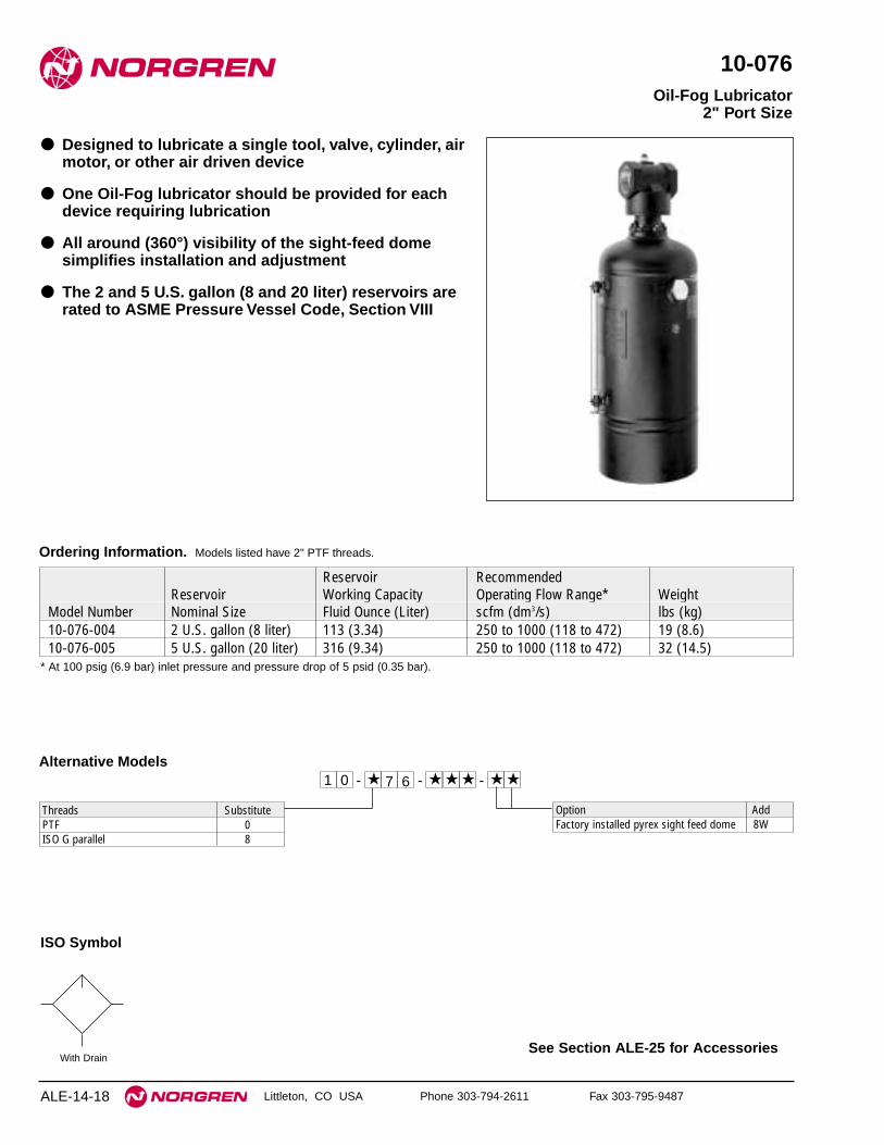
See Section ALE-25 for Accessories
ALE-14-18 Littleton, CO USA Phone 303-794-2611 Fax 303-795-9487
10-076
● Designed to lubricate a single tool, valve, cylinder, airmotor, or other air driven device
● One Oil-Fog lubricator should be provided for eachdevice requiring lubrication
● All around (360°) visibility of the sight-feed domesimplifies installation and adjustment
● The 2 and 5 U.S. gallon (8 and 20 liter) reservoirs arerated to ASME Pressure Vessel Code, Section VIII
Oil-Fog Lubricator2" Port Size
ISO Symbol
With Drain
* At 100 psig (6.9 bar) inlet pressure and pressure drop of 5 psid (0.35 bar).
Reservoir RecommendedReservoir Working Capacity Operating Flow Range* Weight
Model Number Nominal Size Fluid Ounce (Liter) scfm (dm3/s) lbs (kg)10-076-004 2 U.S. gallon (8 liter) 113 (3.34) 250 to 1000 (118 to 472) 19 (8.6)10-076-005 5 U.S. gallon (20 liter) 316 (9.34) 250 to 1000 (118 to 472) 32 (14.5)
Ordering Information. Models listed have 2" PTF threads.
Alternative Models7★- ★ ★★ ★6 - -01
Option AddFactory installed pyrex sight feed dome 8W
★
Threads SubstitutePTF 0ISO G parallel 8

10-076 Lubricators
ALE-14-19
All Dimensions in Inches (mm)
Littleton, CO USA Phone 303-794-2611 Fax 303-795-9487
Technical DataFluid: Compressed airMaximum pressure: 250 psig (17 bar)Operating temperature*: 0° to 175°F (-20° to 80°C)* Air supply must be dry enough to avoid ice formation at temperatures below 35°F (2°C).Start point (minimum flow required for lubricator operation) at 90 psig (6.3 bar)
inlet pressure: 240 scfm (123 dm3/s)Typical flow with 90 psig (6.3 bar) inlet pressure and 5 psig (0.35 bar) pressure
drop: 1300 scfm (614 dm3/s)Nominal reservoir sizes:
2 U.S. gallon (8 liter)5 U.S. gallon (20 liter)
Recommended lubricants: See Section ALE-29.Materials
Body and adapter: AluminumReservoir: Steel Reservoir liquid level indicator lens: PyrexSight-feed dome
Standard: Transparent nylonOptional: Pyrex and aluminum
Elastomers: Nitrile
16
12
8
4
0
INL
ET
PR
ES
SU
RE
bar
240
200
160
120
80
40
0
psi
g
0 200 400 600 800 1000 dm3/s
AIR FLOW
0 400 800 1200 1600 2000 scfm
OPERATING RANGE
A B
A: Minimum flow based on oil drip rate of 5 drops per minute.B: Maximum flow based on pressure drop of 5 psid (0.35 bar).
Oil: SAE 10Oil Feed Setting: Maximum
Typical Performance Characteristics
Reservoir A B C D2 gallon (8 liter) 7.81 (198) 7.18 (182) 21.53 (547) 35 (887)5 gallon (20 liter) 11.81 (300) 11.18 (284) 24.78 (629) 40 (1014)
C
5.13 (130)
2.31
(59)
2 and 5 gallon (8 and 20 liter) reservoir
** Optional pyrex sight-feed dome.† Minimum clearance required to remove bowl.
D †
A
B
3.15
(8
0)**
Reservoir sight glass kits include sight glass, sight glass guards,seals, and hardware.
Service KitsItem Type Part NumberLiquid level lens kit 8 and 20 liter reservoir 2274-01Replacement drain Manual petcock 684-01
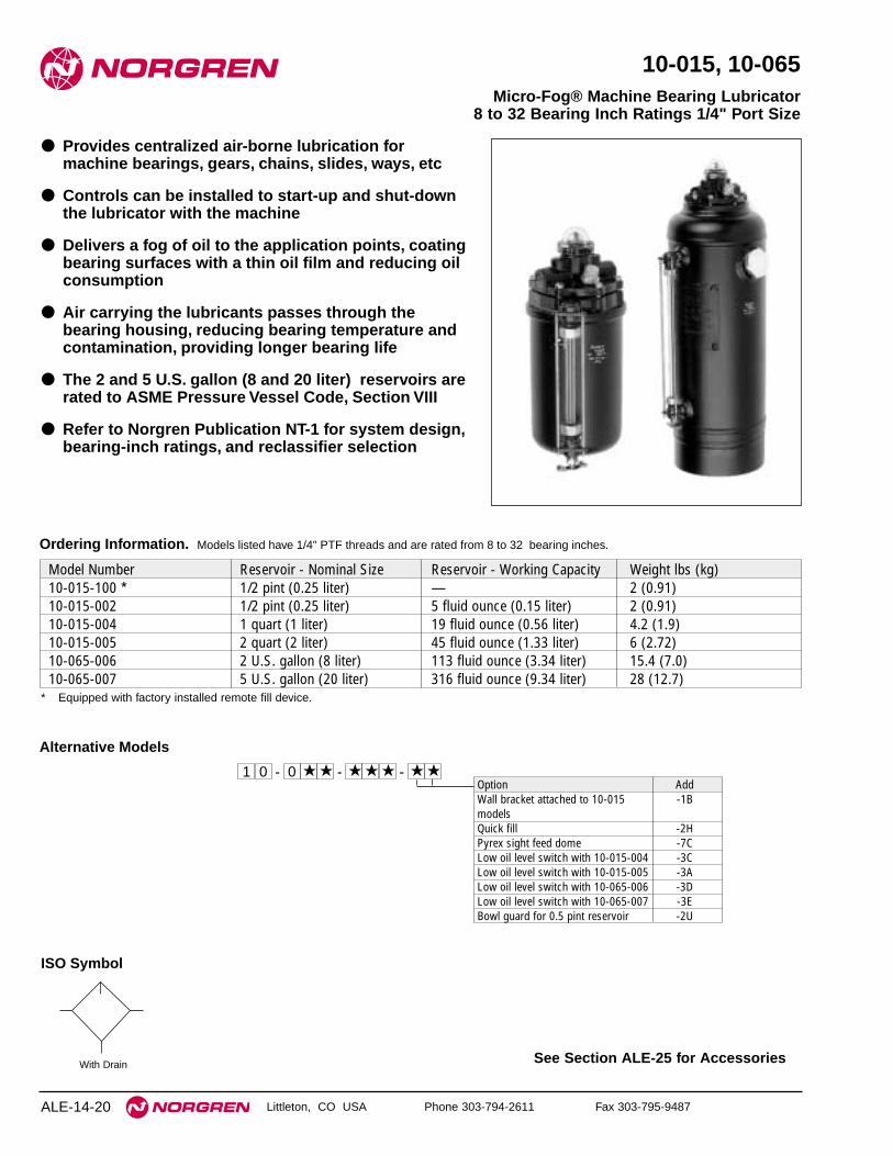
See Section ALE-25 for Accessories
ALE-14-20 Littleton, CO USA Phone 303-794-2611 Fax 303-795-9487
10-015, 10-065
● Provides centralized air-borne lubrication formachine bearings, gears, chains, slides, ways, etc
● Controls can be installed to start-up and shut-downthe lubricator with the machine
● Delivers a fog of oil to the application points, coatingbearing surfaces with a thin oil film and reducing oilconsumption
● Air carrying the lubricants passes through thebearing housing, reducing bearing temperature andcontamination, providing longer bearing life
● The 2 and 5 U.S. gallon (8 and 20 liter) reservoirs arerated to ASME Pressure Vessel Code, Section VIII
● Refer to Norgren Publication NT-1 for system design,bearing-inch ratings, and reclassifier selection
Micro-Fog® Machine Bearing Lubricator8 to 32 Bearing Inch Ratings 1/4" Port Size
ISO Symbol
With Drain
Model Number Reservoir - Nominal Size Reservoir - Working Capacity Weight lbs (kg)10-015-100 * 1/2 pint (0.25 liter) — 2 (0.91)10-015-002 1/2 pint (0.25 liter) 5 fluid ounce (0.15 liter) 2 (0.91)10-015-004 1 quart (1 liter) 19 fluid ounce (0.56 liter) 4.2 (1.9)10-015-005 2 quart (2 liter) 45 fluid ounce (1.33 liter) 6 (2.72)10-065-006 2 U.S. gallon (8 liter) 113 fluid ounce (3.34 liter) 15.4 (7.0)10-065-007 5 U.S. gallon (20 liter) 316 fluid ounce (9.34 liter) 28 (12.7)
Ordering Information. Models listed have 1/4" PTF threads and are rated from 8 to 32 bearing inches.
* Equipped with factory installed remote fill device.
Alternative Models
★0- ★ ★★ ★★ - -01Option AddWall bracket attached to 10-015 -1BmodelsQuick fill -2HPyrex sight feed dome -7CLow oil level switch with 10-015-004 -3CLow oil level switch with 10-015-005 -3ALow oil level switch with 10-065-006 -3DLow oil level switch with 10-065-007 -3EBowl guard for 0.5 pint reservoir -2U
★

10-015, 10-065 Lubricators
ALE-14-21
All Dimensions in Inches (mm)
Littleton, CO USA Phone 303-794-2611 Fax 303-795-9487
Technical DataFluid: Compressed airMaximum pressure
Transparent bowl: 150 psig (10 bar)Metal bowl: 250 psig (17 bar)
Operating temperature*Transparent bowl: 0° to 125°F (-20° to 50°C)Metal bowl: 0° to 175°F (-20° to 80°C)
* Air supply must be dry enough to avoid ice formation at temperatures below 35°F (2°C).Nominal reservoir sizes
10-015-002: 1/2 pint (0.25 liter)10-015-100: 1/2 pint (0.25 liter)10-015-004: 1 quart (1 liter)10-015-005: 2 quart (2 liter)10-065-006: 2 U.S. gallon (8 liter)10-065-007: 5 U.S. gallon (20 liter)
Recommended lubricants: See Section ALE-29.Materials
Body: ZincBowl
Transparent 1/2 pint (0.25 liter): PolycarbonateMetal 1 and 2 quart, 2 and 5 gallon (1, 2, 8, 20 liter): Steel
Metal bowl liquid level indicator lens: PyrexSight-feed dome
Standard: PolycarbonateOptional: Pyrex and brass
Elastomers: Neoprene and nitrile
3.38 (86)
3.81
(97
)
1.92
(49)
7.52
(19
1)
1.91
(49)
9.45
(24
0) *
*
5.60
(14
2)
A
DB
3.38 (86)
1.92
(49)
10-015-002 1/2 pint (0.25 liter) reservoir
10-015-004/-0051 and 2 quart (1 and 2 liter) reservoir
10-065-006/-007 2 and 5 gallon (8 and 20 liter) reservoir
C
** Minimum clearance required to remove bowl.
B A
3.38 (86)
1.92
(49)
D CE *
*
E *
*Reservoir A B C D E1 quart (1 liter) 4.72 (120) 4.06 (103) 9.44 (240) 7.52 (191) 14 (356)2 quart (2 liter) 5.28 (134) 4.63 (118) 11.69 (297) 9.77 (248) 18 (457)2 gallon (8 liter) 7.81 (198) 7.18 (182) 19.51 (496) 17.59 (447) 31 (787)5 gallon (20 liter) 11.81 (300) 11.18 (284) 22.76 (578) 20.84 (529) 36 (914)
Service kit 714-01 includes dome, o-rings, gaskets, siphon tubefilter, siphon tube check ball.Reservoir sight glass kits include sight glass, sight glass guards,seals, and hardware.
Service KitsItem Type Part NumberService kit Seal & Gasket 714-01Liquid level lens kit 1 quart reservoir 2272-02
2 quart reservoir 2273-042 and 5 gallon reservoir 2274-01
Replacement drain Manual petcock 684-01

10-015, 10-065 Lubricators
Littleton, CO USA Phone 303-794-2611 Fax 303-795-9487ALE-14-22
Machine Bearing LubricatorsMachine bearing lubricators deliver a fog of small oil particles through amanifold system to various machine elements (bearings, gears, chains, etc).At the machine elements a nozzle-like fitting, called a reclassifier, causes thesmall oil particles to combine into larger particles. The larger particles coverthe bearing surfaces with a protective film of clean oil. An air line filter andpressure regulator must be installed immediately upstream of the lubricator.
How to SelectSelection requires a careful analysis of the lubrication requirements of themachine. After the analysis, the proper lubricator, reservoir, and reclassifiersmay be ordered. The following is an abbreviated summary of the stepsrequired to analysis lubrication requirements of the machine. See NorgrenPublications NT-1, Design Manual for Machine Lubrication, for completedetails.1. Determine the bearing inch requirement.
a. List and identify the bearing-inch rating of all machine elements requiring lubrication.b. List the reclassifier ratings required at each point of lubrication.c. Total the reclassifier ratings. This is the bearing-inch requirement to use in selecting the lubricator.
2. Determine reservoir capacity required.a. Calculate rate of oil usage based on bearing-inch rating.b. Determine how often the reservoir can be refilled.c. Select reservoir capacity.
3. Determine the air flow required. See the OperatingRanges and Air Flow Requirements chart for air flowrequirements of the lubricator.
4. Determine any accessories required.
Straight, compression tube Elbow, compression tube Pressure jet, compression tube Straight, pipe thread* 1/4 OD copper tube, solderModel BI Rating Model BI Rating Model BI Rating Model BI Rating Model BI Rating
18-009-003 0 to 1 18-009-008 0 to 1 18-009-030 0 to 1 18-009-001 0 to 1 18-009-029 2 to 418-009-010 1 to 2 18-009-011 1 to 2 18-009-031 1 to 2 18-009-002 0 to 118-009-012 2 to 4 18-009-013 2 to 4 18-009-032 2 to 4 18-009-005 2 to 418-009-014 4 to 8 18-009-015 4 to 8 18-009-006 2 to 4
18-009-007 4 to 8
Reclassifiers with Bearing Inch (BI) Ratings - Dimensions in mm (inches)
0.5 (13) 1.25 (32)
1/8 NPT
0.5 (13) 1.19 (30)
1/8 NPT
0.5 (13)
1.75 (45)
1 (25)
1 (2
5)
1/8 NPT
1.25
(32
)
0.69(18) 1.47 (37)
0.75 (19)
Copper Tube
* 1/4 NPT female x 1/8 NPT male threads all models except 18-009-002 and -006, which have 1/4 NPT female and male threads.
Operating Ranges and Air Flow RequirementsBearing Lubricator ManifoldInch Inlet Pressure Air Flow PressureRequirement psig (bar) scfm (dm3/s) Inches H2O16 8 (0.6) 1.6 (0.76) 824 17 (1.2) 2.4 (1.13)32 26 (1.8) 3.1 (1.46)16 10 (0.7) 1.8 (0.85) 1024 20 (1.4) 2.7 (1.27)32 31 (2.2) 3.6 (1.70)16 12 (0.8) 2.0 (0.94) 1224 23 (1.7) 3.0 (1.42)32 35 (2.4) 4.0 (1.89)8 6 (0.4) 1.1 (0.52) 1516 15 (1.0) 2.2 (1.04)24 26 (1.8) 3.3 (1.56)32 40 (2.8) 4.5 (2.12)

Littleton, CO USA Phone 303-794-2611 Fax 303-795-9487 ALE-15-1
Section 15
V07 Miniature Pressure Relief Valve 1/8" and 1/4" Port Sizes . . . . . . . . . . . . . . . . . . . . . .ALE-15-2
V72 Excelon Pressure Relief Valve 1/4" and 3/8" Port Sizes . . . . . . . . . . . . . . . . . . . . . .ALE-15-4
V74 Excelon Pressure Relief Valve 3/8", 1/2", and 3/4" Port Sizes . . . . . . . . . . . . . . . . .ALE-15-6
V64 Olympian Plus Pressure Relief Valve 1/4", 3/8", 1/2", and 3/4" Port Sizes . . . . . . . . . . . . .ALE-15-8
V68H Olympian Plus Pressure Relief Valve 3/4", 1", 1-1/4", and 1-1/2" Port Sizes . . . . . . . . . . .ALE-15-10
16-004 Miniature Brass Body Tank Relief Valve 1/8" and 1/4" Port Sizes . . . . . . . . . . . . . . . . . . . . .ALE-15-12
V06 Miniature Brass Body Relief Valve for Water andCompressed Air 1/8" and 1/4" Port Sizes . . . . . . .ALE-15-14
Function and Sizing . . . . . . . . . . . . . . . . . . . . . . . . . . .ALE-15-16
Pressure Relief ValvesCompressed air Relief Valvesfrom 1/8" to 1-1/2" port size.Water Relief Valve in 1/8" and1/4" port. Tank Relief Valve in1/8" and 1/4" port size.
V07 V72G V74G
V64H V68H 16-004 V06
Product available1st quarter of 2001
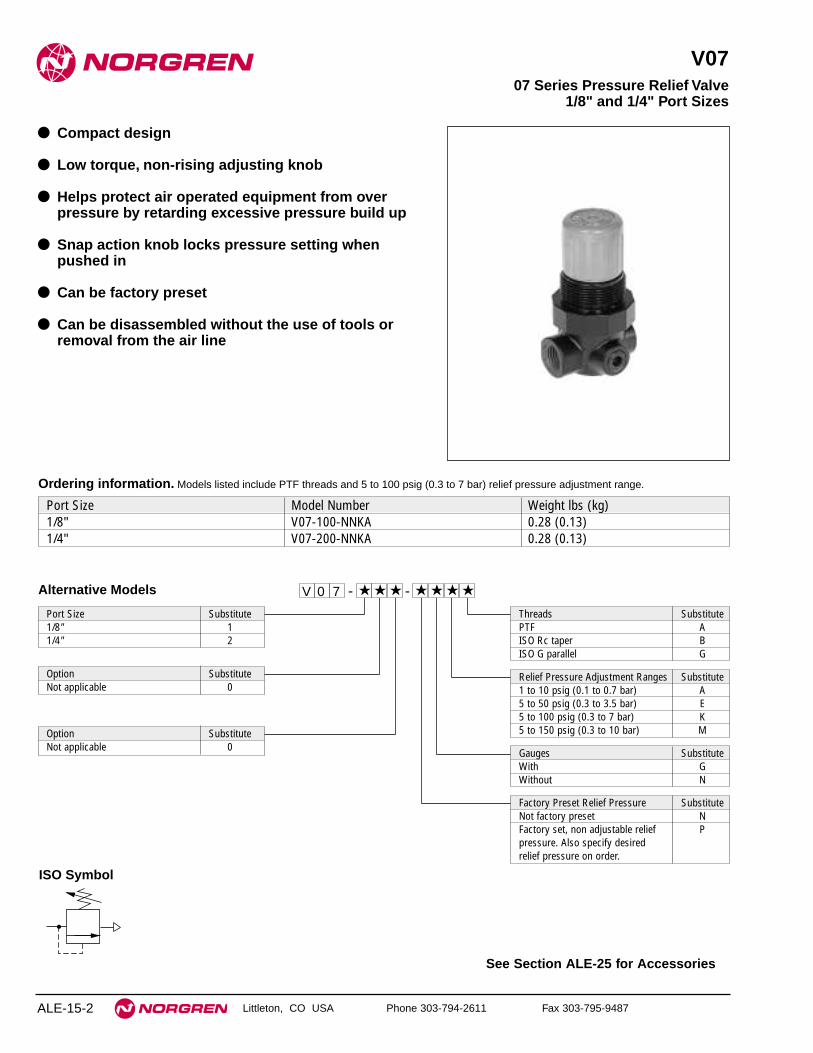
Littleton, CO USA Phone 303-794-2611 Fax 303-795-9487
V07
● Compact design
● Low torque, non-rising adjusting knob
● Helps protect air operated equipment from overpressure by retarding excessive pressure build up
● Snap action knob locks pressure setting whenpushed in
● Can be factory preset
● Can be disassembled without the use of tools orremoval from the air line
07 Series Pressure Relief Valve1/8" and 1/4" Port Sizes
ALE-15-2
See Section ALE-25 for Accessories
Alternative Models
Port Size Substitute1/8" 11/4" 2
Threads SubstitutePTF AISO Rc taper BISO G parallel G
Port Size Model Number Weight lbs (kg)1/8" V07-100-NNKA 0.28 (0.13)1/4" V07-200-NNKA 0.28 (0.13)
Ordering information. Models listed include PTF threads and 5 to 100 psig (0.3 to 7 bar) relief pressure adjustment range.
Option SubstituteNot applicable 0
Relief Pressure Adjustment Ranges Substitute1 to 10 psig (0.1 to 0.7 bar) A5 to 50 psig (0.3 to 3.5 bar) E5 to 100 psig (0.3 to 7 bar) K5 to 150 psig (0.3 to 10 bar) MOption Substitute
Not applicable 0 Gauges SubstituteWith GWithout N
Factory Preset Relief Pressure SubstituteNot factory preset NFactory set, non adjustable relief Ppressure. Also specify desired relief pressure on order.
- ★★★ ★★ ★ -0 ★V 7
ISO Symbol

V07 Series Pressure Relief Valve
Littleton, CO USA Phone 303-794-2611 Fax 303-795-9487 ALE-15-3
All Dimensions in Inches (mm)
Technical DataFluid: Compressed airMaximum pressure: 300 psig (20 bar)Operating temperature: -30° to 150°F (-34° to 65°C) *
* Air supply must be dry enough to avoid ice formation at temperatures below 35°F (2°C).
Gauge ports:1/8" PTF with PTF main ports1/8" ISO Rc with ISO Rc main ports1/8" ISO Rc with ISO G main ports
Materials:Body: ZincBonnet: AcetalValve seat: PolyphenyleneElastomers: Nitrile
RELIEF FLOW CHARACTERISTICS
0 2 4 6 8 10 dm3/s
AIR FLOW
0 4 8 12 16 20 24 scfm
iNL
ET
PR
ES
SU
RE
8
6
4
2
0
bar
g
100
80
60
40
20
0
psi
g
PORT SIZE: 1/4"
RANGE: 5 to 125 psig (0.3 to 9 bar)
Typical Performance Characteristics
0.95
(24) 2.
55 (
68)
2.91
(75
)
1.50
(38
)
1.1 (28)
1.63 (41)
0.73(19)
0.91(23)
Panel mounting hole diameter: 1.19" (30 mm)Maximum panel thickness: 0.25" (6 mm)
Service KitsItem Type Part number
Diaphragm and valve seat seal 3407-80Service kits Valve seat and valve seat seal 3439-11
Diaphragm seat and seal 3407-19

Littleton, CO USA Phone 303-794-2611 Fax 303-795-9487
V72G
● Excelon design allows in-line or modular installation
● Push to lock adjusting knob with tamper resistantaccessory
● Helps protect air operated equipment from overpressure by retarding excessive pressure build up
● Modular installations with Excelon 72, 73, and 74series can be made to suit particular applications
● Relief port located on bottom allows easy installation
72 Series Pressure Relief Valve 1/4", 3/8" Port Size
ALE-15-4
See Section ALE-25 for Accessories
Ordering Information. Models listed include PTF threads, knob adjustment, and a 5 to 150 psig (0.3 to 10 bar) outlet pressure adjustment range*.
Port Size Model Weight lb (kg)1/4" V72G-2AK-NMN 0.73 (0.33)3/8" V72G-3AK-NMN 0.73 (0.33)
V 7 2 -G ★ ★ - ★★ N ★
Port Size Substitute1/4" 23/8" 3
Threads SubstitutePTF AISO Rc taper BISO G parallel G
Gauge SubstituteWith GWithout N
Alternative Models
Outlet Pressure Adjustment Range* Substitute5 to 30 psig (0.3 to 2 bar) C5 to 60 psig (0.3 to 4 bar) F5 to 150 psig (0.3 to 10 bar) M
* Relief valve can be adjusted to pressures inexcess of and less than those specified. Do notuse these units to control pressures outside ofthe specified ranges.
Adjustment SubstituteKnob KT-bar T
ISO Symbol

V72G Pressure Relief Valve
Littleton, CO USA Phone 303-794-2611 Fax 303-795-9487 ALE-15-5
All Dimensions in Inches (mm)
Technical DataFluid: Compressed airMaximum pressure: 300 psig (20 bar)Operating Temperature*: -30° to 150°F (-34° to 65°C)
* Air supply must be dry enough to avoid ice formation at temperatures below 35°F (2°C).Gauge Ports:
1/8" PTF with PTF main ports1/8" ISO Rc with ISO Rc main ports1/8" ISO Rc with ISO G main ports
Exhaust Port:1/4" PTF with PTF main ports1/4" ISO Rc with ISO Rc main ports1/4" ISO Rc with ISO G main ports
MaterialsBody: ZincBonnet: AcetalValve: BrassElastomers: NeopreneBottom Plug: Acetal
Typical Performance Characteristics
PORT SIZE: 1/4"RANGE: 5 to 150 psig (0.3 to 10 bar g)
RELIEF CHARACTERISTICS
0 5 10 15 20 25 dm3/s
AIR FLOW
0 10 20 30 40 50 60 scfm
INL
ET
PR
ES
SU
RE
12
9
6
3
0
bar
g
150
120
90
60
30
0
psi
g
2.88
(73
)
1.97 (50)
1.89
(48
)
1.38
(35
)
1.97 (50)
2.48 (63)
1.89
(48
)
1.38
(35
)
4.03
(10
2)
0.98
(25
)
0.98
(25
)
1.01
(26
)
1.01
(26
)
1/4" exhaust port 1/4" exhaust port
Panel mounting hole diameter: 1.57" (40 mm)Maximum panel thickness: 0.16" (4 mm)

Littleton, CO USA Phone 303-794-2611 Fax 303-795-9487
V74G
● Excelon design allows in-line or modular installation
● Push to lock adjusting knob with tamper resistantaccessory
● Easily disassembled for servicing without removalfrom air line
● Helps protect air operated equipment from overpressure by retarding excessive pressure build up
● Modular installations with Excelon 72, 73, and 74series can be made to suit particular applications
74 Series Pressure Relief Valve3/8", 1/2", 3/4" Port Sizes
ALE-15-6
See Section ALE-25 for Accessories
Alternative Models
Ordering Information. Models listed include PTF threads, knob adjustment, and a 5 to 150 psig (0.3 to 10 bar) relief pressure adjustment range*.
V 7 4 -G ★ ★ - ★★ N ★
Threads SubstitutePTF AISO Rc taper BISO G parallel G
Adjustment SubstituteKnob KT-bar T
Port Size Model Weight lb (kg)3/8" V74G-3AK-NMN 0.69 (1.53)1/2" V74G-4AK-NMN 0.68 (1.50)3/4" V74G-6AK-NMN 0.67 (1.47)
Gauge SubstituteWith GWithout N
Relief PressureAdjustment Range* Substitute5 to 60 psig (0.3 to 4 bar) F5 to 150 psig (0.3 to 10 bar) M10 to 250 psig (0.7 to 17 bar)** S
* Relief valve can be adjusted to pressures in excess of, and less than, those specified. Do not use these units to control pressures outside of the specified ranges.
** Units with 250 psig (17 bar) relief pressure range are available only with the T-bar adjustment; therefore substitute T at the 7th position and S at the 9th position.
Port Size Substitute3/8" 31/2" 43/4" 6
ISO Symbol

V74G Pressure Relief Valves
Littleton, CO USA Phone 303-794-2611 Fax 303-795-9487 ALE-15-7
All Dimensions in Inches (mm)
Technical DataFluid: Compressed airMaximum pressure: 300 psig (20 bar)Operating temperature*: -30° to 175°F (-34° to 80°C)* Air supply must be dry enough to avoid ice formation at temperatures below 35°F (2°C).
Gauge ports:1/4" PTF with PTF main portsRc1/4 with ISO Rc main portsRc1/8 with ISO G main ports
MaterialsBody: AluminumBonnet: AluminumValve: Aluminum and NitrileElastomers: NitrileBottom plug: Acetal
Typical Performance Characteristics
0 20 40 60 80 100 dm3/s
AIR FLOW
0 40 80 120 160 200 scfm
INL
ET
PR
ES
SU
RE 6
4
2
0
bar
g
100
80
60
40
20
0
psi
g
PORT SIZE: 1/2"RANGE: 5 to 150 psig (0.3 to 10 bar)
RELIEF CHARACTERISTICS
2.89
(74
)2.
20 (
56)
1.69
(43
)4.
98 (
127)
1.45
(37
)
3.15 (80)
2.00 (50)
1.24
(31
)
5.95
(15
1)Optional
Gauge
Service Kits
Service kit includes diaphragm, bottom plug o-ring.
Item Type Part NumberService kit Diaphragm & Seal 4384-700
Panel mounting hole diameter: 2.06" (52 mm)Maximum panel thickness: 0.25" (6 mm)

Littleton, CO USA Phone 303-794-2611 Fax 303-795-9487
V64H
● Olympian Plus plug in design
● Helps protect air operated equipment from overpressure by retarding excessive pressure build up
● High relief capacity
● Threaded relief port for silencer or piped exhaust
● Relief port located on bottom allows easy installation
Olympian Plus Pressure Relief Valve1/4", 3/8", 1/2", 3/4" Port Sizes
ALE-15-8
See Section ALE-25 for Accessories
Ordering Information. Models listed include PTF threads, 5 to 150 psig (0.3 to 10 bar) operating pressure range* without gauge.
For replacement relief valve (without yoke) substitute ‘N’ at the 5th and 6th digits eg: V64H-NND-RMN.
Port Size Model Weight lb (kg)1/4" V64H-2AD-RMN 3.73 (1.68)3/8" V64H-3AD-RMN 3.69 (1.66)1/2" V64H-4AD-RMN 3.62 (1.63)3/4" V64H-6AD-RMN 4.42 (1.99)
V 6 4 -H ★ ★ - ★★ R ★
Threads SubstitutePTF AISO Rc taper BISO G parallel G Adjustment Substitute
Slotted screw D
Gauge SubstituteWith GWithout N
* Relief valve can be adjusted to pressures in excess of,and less than, those specified. Do not use these unitsto control pressures outside of the specified ranges.
Alternative Models
Outlet Pressure Adjustment Range* Substitute5 to 60 psig (0.3 to 4 bar) F15 to 150 psig (1 to 10 bar) M10 to 250 psig (0.7 to 17 bar) S
Port Size Substitute1/4" 23/8" 31/2" 43/4" 6
ISO Symbol

V64H Pressure Relief Valve
Littleton, CO USA Phone 303-794-2611 Fax 303-795-9487 ALE-15-9
All Dimensions in Inches (mm)
Technical DataFluid: Compressed airMaximum pressure: 300 psig (20 bar)Operating temperature*: -30° to 175°F (-34° to 80°C)
* Air supply must be dry enough to avoid ice formation at temperatures below 35°F (2°C).Gauge ports:
1/8" PTF with PTF main ports1/8" ISO Rc with ISO Rc main ports1/8" ISO Rc with ISO G main ports
Exhaust port:1/2" PTF with PTF main ports1/2" ISO Rc with ISO Rc main ports1/2" ISO Rc with ISO G main ports
MaterialsBody: ZincBonnet: ZincBottom plug: Aluminum alloyYoke: ZincAdjusting screw: SteelValve: BrassElastomers: Synthetic rubber
Typical Performance Characteristics
PORT SIZE: 1/2"RANGE: 15 to 150 psig (1 to 10 bar)
RELIEF CHARACTERISTICS
0 40 80 120 160 200 dm3/s
AIR FLOW
0 80 160 240 320 400 scfm
INL
ET
PR
ES
SU
RE
16
12
8
4
0
bar
g
200
160
120
80
40
0
psi
g
4.13 (105)**
1.46
(37
)
2.91
(74
)8.
07 (
205)
8.70
(22
1)†
1.38
(35
)
Panel mounting hole diameter: 2.06" (52 mm)Maximum panel thickness: 0.16" (4 mm)** 6.18" (157 mm) for models with 3/4" ports
† Minimum clearance required to remove unit.
Service KitsItem Type Part NumberService kit All models 4384-200Gasket kit All models V13-GK
Service kit includes port and bottom plug o-rings, gasket, slip ring,valve assembly, valve spring, diaphragm, diaphragm stop and pilotvalve assembly.

ALE-15-10 Littleton, CO USA Phone 303-794-2611 Fax 303-795-9487
V68H
● Olympian plug in design
● Helps protect compressed air systems from overpressure by retarding excessive pressure build up
● High relief capacity, sensitive and accurate
● Integral pilot operated design, suitable for in-line orindirect mounting
● Threaded relief port for silencer or piped exhaust
Olympian Pressure Relief Valve3/4", 1", 1-1/4", 1-1/2", Port Sizes
Ordering Information. Models listed include PTF threads, 1 to 10 bar (15 to 150 psig) operating adjustment range* without gauge.
Port Size Model Weight kg (lb)3/4" V68H-6AD-RMN 2,21 (4.91)1" V68H-8AD-RMN 2,20 (4.89)1-1/4" V68H-AAD-RMN 2,22 (4.93)1-1/2" V68H-BAD-RMN 2,26 (5.02)
Alternative ModelsV H6 -8 ★ ★ - ★★ R ★
Port Size Substitute3/4" 61" 81 1/4" A1 1/2" B
Adjustment SubstituteSlotted screw D
Gauge SubstituteWith GWithout N
Thread SubstitutePTF AISO Rc taper BISO G parallel G
Outlet Pressure Adjustment Range* Substitute0,4 to 4 bar (0 to 60 psig) F1 to 10 bar (15 to 150 psig) M0.7 to 17 bar (10 to 250 psig) S
* Relief valve can be adjusted to pressures inexcess of, and less than, those specified.Do not use these units to control pressuresoutside of the specified ranges.
ISO Symbol
68 Series products are available 1st quarter of 2001. Visit www.norgren.com for the latestdata on this series.

V68H Pressure Relief Valves
ALE-15-11
All Dimensions in Inches (mm)
Littleton, CO USA Phone 303-794-2611 Fax 303-795-9487
Technical DataFluid: Compressed airOperating temperature*:
0° to 175°F (-20° to 80°C)
* Air supply must be dry enough to avoid ice formation at temperatures below 35°F (2°C).Gauge ports: 1/8" PTFExhaust port: 1" PTFMaterials
Body: AluminiumIntermediate body: AluminiumBonnet: AluminiumBottom plug: AluminiumAdjusting screw: SteelElastomers: Synthetic rubber Yoke: Aluminium
Typical Performance CharacteristicsFLOW CHARACTERISTICS
0 50 100 150 200 250 dm3/s
AIR FLOW
0 100 200 300 400 500 600 scfm
16
14
12
10
8
6
4
2
0
INL
ET
PR
ES
SU
RE
bar
g
200
160
120
80
40
0
psi
g
UNPORTEDRANGE: 15 to 150 psig (1 to 10 bar)
* Reduces by 4 mm (0.16") with knob in lockedposition. Add 37 mm (1.46”) for unit with T-handle
† Minimum clearance required to remove unit.
4.12 (125)
10.1
(25
6)†
1.97
(50
)9.
13 (
232)
G1/8
2.13
(54
)68 Series products are available 1st quarter of 2001. Visit www.norgren.com for the latestdata on this series.

See Section ALE-25 for Accessories
ALE-15-12 Littleton, CO USA Phone 303-794-2611 Fax 303-795-9487
16-004
● Used in low-volume air tanks to retard excessivepressure buildup
● If pressure exceeds the relief pressure setting, thevalve opens and air from the tank is vented toatmosphere. Valve closes when pressure is reducedto the relief pressure setting.
● Compact design, corrosion resistant construction
● Constructed of brass and stainless steel forcompressed air and water service
● Available with adjustable or non-adjustable, factorypreset, relief pressure setting
Miniature Brass Body Tank Relief ValveCompressed Air Service
1/8" and 1/4" PTF Port Sizes
Ordering information
Model Numbers - Relief Pressure Adjustment Ranges *25 to 50 psig 25 to 75 psig 70 to 150 psig 125 to 300 psig
Port Size (1.7 to 3.5 bar) (1.7 to 5.2 bar) (5 to 10.4 bar) (8.6 to 20.7 bar) Weight lbs (kg)1/8" 16-004-001 16-004-002 16-004-003 16-004-004 0.11 (0.05)1/4" 16-004-009 16-004-010 16-004-011 16-004-012 0.11 (0.05)
Alternative Models
Factory Set Relief Pressure Setting Add **Insert desired relief pressure setting 025 throughin psig 300
00- ★ ★ ★★ ★4 - -61 ★ ★
Factory set, non adjustable pressure Add **Locktite adjusting cap Z
* Relief valves can be adjusted to pressures in excess of, and less than, those specified. Do not use these units to control pressures outside of the specified ranges.
** Example: 16-004-001-Z025Locking method: Locktite capRelief pressure setting: 25 psig
ISO Symbol

16-004 Tank Relief Valve
ALE-15-13
All Dimensions in Inches (mm)
Littleton, CO USA Phone 303-794-2611 Fax 303-795-9487
Technical DataFluid: Compressed air and waterMaximum pressure: 300 psig (20 bar)Operating temperature*: -30° to 200°F (-34° to 93°C)*Air supply must be dry enough to avoid ice formation at temperatures below 35°F (2°C).Repeatability: ± 20% of relief pressure settingMaterials
Body, cap, springrest: BrassValve: Brass and nitrileRegulating spring: Stainless steel
RELIEF FLOW CHARACTERISTICS - AIR
0 0.5 1 1.5 2 2.5 dm3/sAIR FLOW
0 1 2 3 4 5 6 scfm
INL
ET
PR
ES
SU
RE
8
6
4
2
0
bar
100
80
60
40
20
0
psi
g
50 (3.5)
25 (1.7)
SET RELIEFPRESSURE: psig (bar)
PORT SIZE: 1/8", 1/4"SPRING RANGE:25 to 50 psig (1.7 to 3.5 bar)
Typical Performance Characteristics
RELIEF FLOW CHARACTERISTICS - AIR
0 0.5 1 1.5 2 2.5 dm3/sAIR FLOW
0 1 2 3 4 5 6 scfm
INL
ET
PR
ES
SU
RE
8
6
4
2
0
bar
100
80
60
40
20
0 p
sig
75 (5.2)
50 (3.5)
25 (1.7)
SET RELIEFPRESSURE: psig (bar)
PORT SIZE: 1/8", 1/4"SPRING RANGE:25 to 75 psig (1.7 to 5.2 bar)
RELIEF FLOW CHARACTERISTICS - AIR
0 0.5 1 1.5 2 2.5 dm3/sAIR FLOW
0 1 2 3 4 5 6 scfm
INL
ET
PR
ES
SU
RE
100
80
60
40
20
0
psi
g
180
160
140
1208
6
4
2
0
bar
12
10
PORT SIZE: 1/8", 1/4"SPRING RANGE:50 to 150 psig (2.4 to 10.4 bar)
SET RELIEFPRESSURE: (psig (bar)
150 (10.3)
100 (6.9)
50 (3.5)
0.79 (20) Dia.
A
A: 1.56 (62) for 1/8" pipe size 1.75 (44) for 1/4" pipe size

See Section ALE-25 for Accessories
ALE-15-14 Littleton, CO USA Phone 303-794-2611 Fax 303-795-9487
V06
● Helps protect water systems from excessive pressurebuildup by venting water when pressure exceedssetting of the relief valve. Relief valve closes whenpressure is reduced to the relief pressure setting.
● Compact design, corrosion resistant construction
● Brass body with choice of plastic or brass bonnet
● Plastic bonnet equipped with low torque, non-risingpressure adjusting knob. Snap action knob lockspressure setting when pushed in
● Brass bonnet equipped with pressure adjustingscrew and locknut
● Can be disassembled without the use of tools orremoval from the air line
● Can be factory preset
Miniature Brass Body Relief ValveWater and Compressed Air Service
1/8" and 1/4" PTF Port Sizes
Alternative Models0V 6 ★ ★ ★ ★★ -★ ★ -
Port Size Substitute1/8" 11/4" 2
Threads SubstitutePTF A
Relief Pressure Adjustment Range† Substitute1 to 10 psig (0.1 to 0.7 bar) A5 to 50 psig (0.3 to 3.5 bar) E5 to 100 psig (0.3 to 7 bar) K
Gauges SubstituteWith GWithout N
Factory Set Relief Pressure SubstituteNot factory set NFactory set, non adjustable relief Ppressure. Also specify desired relief pressure on order.
Bonnet SubstitutePlastic 21Brass 22
† Relief valve can be adjusted to pressures in excess of, and less than, those specified. Do not use these units to control pressures outside of the specified ranges.
Ordering information. Models listed include PTF threads, plastic bonnet with knob adjustment, and 5 to 100 psig (0.3 to 7 bar) relief pressure
adjustment range.† A gauge is not included.
Port Size Model Number Weight lbs (kg)1/8" V06-121-NNKA 0.2 (0.09)1/4" V06-221-NNKA 0.2 (0.09)
ISO Symbol

V06 Relief Valve
ALE-15-15
All Dimensions in Inches (mm)
Littleton, CO USA Phone 303-794-2611 Fax 303-795-9487
Technical DataFluid: Water and compressed airMaximum pressure: 400 psig (27.6 bar)Operating temperature:
Plastic bonnet: 35° to 150°F (2° to 65°C)Brass bonnet: 35° to 175°F (2° to 79°C)
Gauge ports: 1/8" PTFMaterials
Body: BrassBonnet
Standard: Acetal resin Optional: Brass
Valve seat: Acetal resinElastomers: Nitrile
PORT SIZE 1/8" SPRING RANGE: 5 to 100 psig (0.3 TO 7 bar)
RELIEF FLOW CHARACTERISTICS - WATER
0 4 8 12 16 20 liters/minWATER FLOW
0 1 2 3 4 5 U.S. gal./min
INL
ET
PR
ES
SU
RE
8
6
4
2
0
bar
100
80
60
40
20
0
psi
g
SET RELIEF PRESSURE: psig (bar)80 (5.5)
60 (4.1)
40 (2.8)
20 (1.4)
Typical Performance Characteristics
0.91
(23)
2.46
(63
)
2.86
(73
)
1.1 (28)
1.03
(26
) 3.01
(77
)
3.41
(87
)
Models with Plastic Bonnet Models with Brass Bonnet
1.50
(38
)
1.50 (38)
1.50
(38
)
1.50 (38)
2.13
(54
)
1.57 (40)
2.13
(54
)
1.57 (40)
Panel mounting hole diameter:Models with plastic bonnet: 1.19" (30 mm)Models with brass bonnet: 0.81" (21mm)
Maximum panel thickness: 0.25" (6 mm)
Service KitsItem Type Part number
Service kitValve seat and seal 3439-11Diaphragm 3440-03
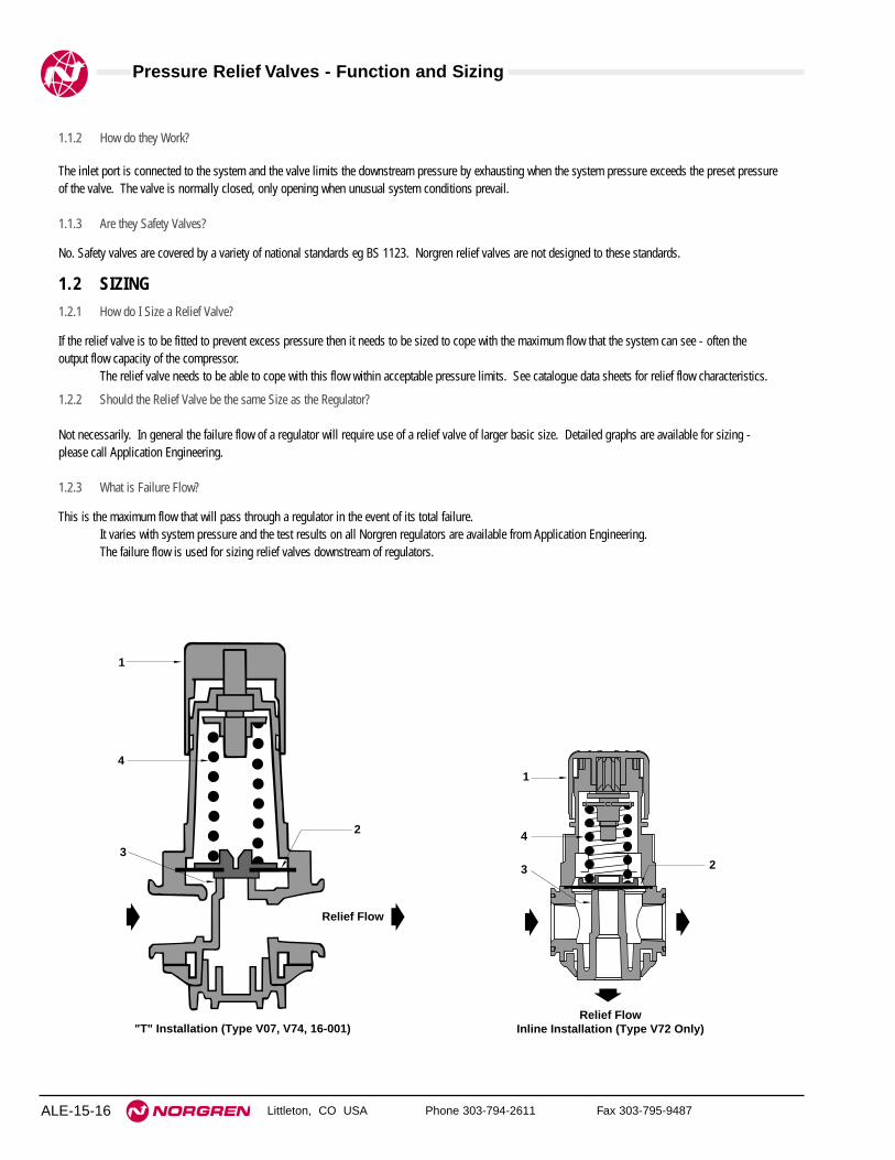
Pressure Relief Valves - Function and Sizing
Littleton, CO USA Phone 303-794-2611 Fax 303-795-9487ALE-15-16
1.1.2 How do they Work?
The inlet port is connected to the system and the valve limits the downstream pressure by exhausting when the system pressure exceeds the preset pressureof the valve. The valve is normally closed, only opening when unusual system conditions prevail.
1.1.3 Are they Safety Valves?
No. Safety valves are covered by a variety of national standards eg BS 1123. Norgren relief valves are not designed to these standards.
1.2 SIZING1.2.1 How do I Size a Relief Valve?
If the relief valve is to be fitted to prevent excess pressure then it needs to be sized to cope with the maximum flow that the system can see - often theoutput flow capacity of the compressor.
The relief valve needs to be able to cope with this flow within acceptable pressure limits. See catalogue data sheets for relief flow characteristics.
1.2.2 Should the Relief Valve be the same Size as the Regulator?
Not necessarily. In general the failure flow of a regulator will require use of a relief valve of larger basic size. Detailed graphs are available for sizing -please call Application Engineering.
1.2.3 What is Failure Flow?
This is the maximum flow that will pass through a regulator in the event of its total failure.It varies with system pressure and the test results on all Norgren regulators are available from Application Engineering.The failure flow is used for sizing relief valves downstream of regulators.
1
4
2
3
"T" Installation (Type V07, V74, 16-001)
Relief Flow
1
4
3 2
Relief FlowInline Installation (Type V72 Only)

Littleton, CO USA Phone 303-794-2611 Fax 303-795-9487 ALE-16-1
Section 16
ContentsT72 Excelon Shut-off & Lockout Valves
1/4", 3/8" Port Sizes . . . . . . . . . . . . . . . . . . . . . . . . . . . . . . . . . . . .ALE-16-2T73 Excelon Shut-Off & Lockout Valves
1/4", 3/8", 1/2" Port Sizes . . . . . . . . . . . . . . . . . . . . . . . . . . . . . . . .ALE-16-4T74 Excelon Shut-Off & Lockout Valves
3/8", 1/2", 3/4" Port Sizes . . . . . . . . . . . . . . . . . . . . . . . . . . . . . . . .ALE-16-6T64 Olympian Plus Shut-off & Lockout Valves
1/4", 3/8", 1/2", 3/4" Port Sizes . . . . . . . . . . . . . . . . . . . . . . . . . . . .ALE-16-8T68 Olympian Plus Shut-off & Lockout Valves
3/4", 1", 1 1/4", 1 1/2" Port Sizes . . . . . . . . . . . . . . . . . . . . . . . . .ALE-16-10C00 Lockout Valves 1/4" through 1-1/2" Port Sizes . . . . . . . . . . .ALE-16-12Option and FAQ’s . . . . . . . . . . . . . . . . . . . . . . . . . . . . . . . . . . . . . .ALE-16-14
Shut-off & Lockout Valves1/4" to 1-1/2" port size
T72 T73 T74
T64 T68 C00
Product available1st quarter of 2001

See Section ALE-25 for Accessories
Littleton, CO USA Phone 303-794-2611 Fax 303-795-9487
T72
● EXCELON design allows in-line installation ormodular installation
● T72B 2-port/2-position shut-off valves no exhaust
● T72T 3-port/2-position shut-off valves with 10-32tapped exhaust
● T72E 3-port/2-position lockout valves help conform toOSHA Lockout Regulations in USA market. Exhaustoutlet is not tapped.
● Valves can be locked in closed position only
● Modular installations with EXCELON 72, 73, and 74series can be made to suit particular applications
Excelon T72 Shut-off & Lockout Valves1/4", 3/8" Port Sizes
ALE-16-2
ISO Symbols
2-Port/2-Position 3-Port/2-Position
Ordering Information. Models listed have PTF threads.
2-Port/2-Position 3-Port/2-Position (OSHA) 3-Port/2-PositionPort Size No Exhaust Outlet Exhaust Port not tapped Threaded Exhaust Port Weight lbs (kg)1/4" T72B-2AA-P1N T72E-2AA-P1N T72T-2AA-P1N 0.79 (0.36)3/8" T72B-3AA-P1N T72E-2AA-P1N T72T-3AA-P1N 0.86 (0.39)
T 7 2 -★ ★ ★ - 1A P ★
Port Size Substitute1/4" 23/8" 3
Threads SubstitutePTF AISO Rc taper BISO G parallel G
Alternative Models
Valve Type Substitute2-port/2-position BBlack slide, No exhaust outlet
3-port/2-position EYellow slide, Unthreaded exhaust outlet3-port/2-position TRed slide, Threaded exhaust port
Options SubstituteNone NT73T with exhaust silencer ST73T with exhaust diffuser D

T72 Shut-off & Lockout Valves
Littleton, CO USA Phone 303-794-2611 Fax 303-795-9487 ALE-16-3
All Dimensions in Inches (mm)
Technical DataFluid: Compressed airMaximum Pressure: 250 psig (17 bar)Operating Temperature*: 0° to 150°F (-20° to 65°C)
* Air supply must be dry enough to avoid ice formation at temperatures below 35°F (2°C).Cv factor from IN to OUT ports
1/4" ports: 4.03/8" ports: 8.0
Cv factor from OUT to EXHAUST ports on 3-port/2-position valves: 0.2.Exhaust port threads on T72T models: 10-32Hole diameter in slide for padlock: 5/16" (8 mm)Materials
Body: ZincSlide: Acetal plasticElastomers: Nitrile
Service KitsItem Type Part NumberService kit Actuator seals and slide 4384-510
Service kit includes actuator seals and slide.
1.97 (50)
1.89
(48
)3.
46 (
88)

See Section ALE-25 for Accessories
Littleton, CO USA Phone 303-794-2611 Fax 303-795-9487
T73
● EXCELON design allows in-line or modularinstallation
● T73B 2-port/2-position shut-off valves no exhaust
● T73T 3-port/2-position shut-off valves with 10-32tapped exhaust
● T73E 3-port/2-position lockout valves help conform toOSHA Lockout Regulations in USA market. Exhaustoutlet is not tapped.
● Valves can be locked in closed position only.
● Modular installations with EXCELON 72, 73, and 74series can be made to suit particular applications
Excelon T73 Shut-Off & Lockout Valves1/4", 3/8", 1/2" Port Sizes
ALE-16-4
ISO Symbols
2-Port/2-Position 3-Port/2-Position
2-Port/2-Position 3-Port/2-Position 3-Port/2-PositionPort Size No exhaust outlet Unthreaded exhaust outlet Threaded exhaust port Weight lbs (kg)1/4" T73B-2AA-P1N T73E-2AA-P1N T73T-2AA-P1N 0.7 (0.3)3/8" T73B-3AA-P1N T73E-3AA-P1N T73T-3AA-P1N 0.7 (0.3)1/2" T73B-4AA-P1N T73E-4AA-P1N T73T-4AA-P1N 0.7 (0.3)
Alternative Models T 7 3 -★ ★ ★ - 1A P ★
Port Size Substitute1/4" 23/8" 31/2" 4
Valve Type Substitute2-port/2-position BBlack slide, No exhaust outlet
3-port/2-position EYellow slide, Unthreaded exhaust outlet3-port/2-position TRed slide, Threaded exhaust port
Threads SubstitutePTF AISO Rc taper BISO G parallel G
Ordering Information. Models listed have PTF parallel threads.
Options SubstituteNone NT73T with exhaust silencer ST73T with exhaust diffuser D

T73 Shut-off & Lockout Valves
Littleton, CO USA Phone 303-794-2611 Fax 303-795-9487 ALE-16-5
Technical DataFluid: Compressed airMaximum pressure: 250 psig (17 bar)Operating temperature: 0° to 150°F (-20° to 65°C)* Air supply must be dry enough to avoid ice formation at temperatures below 35°F (2°C).Cv factor
IN to OUT ports:1/4" ports: 4.03/8" ports: 8.01/2" ports: 7.8
OUT to EXHAUST ports on 3-port/2-position valves: 0.2Exhaust port threads on T73T models: 10-32Hole diameter in slide for padlock: 5/16" (8 mm)Materials
Body: ZincSlide: Acetal plasticElastomers: Nitrile
2.13 (54)
2.32
(59
)3.
46 (
88)
Service kit includes seals and slide.
Service KitsItem Type Part Number
Service kitT73B (black slide) 4384-610T73E (yellow slide) 4384-611T73T (red slide) 4384-612
All Dimensions in Inches (mm)

See Section ALE-25 for Accessories
Littleton, CO USA Phone 303-794-2611 Fax 303-795-9487
T74
● EXCELON design allows in-line or modularinstallation
● T74B 2-port/2-position shut-off valves no exhaust
● T74T 3-port/2-position shut-off valves with 1/8"tapped exhaust
● T74E 3-port/2-position lockout valves help conform toOSHA Lockout Regulations in USA market. Exhaustoutlet is not tapped.
● Valves can be locked in the closed position only
● Modular installations with EXCELON 72, 73, and 74series can be made to suit particular applications
Excelon T74 Shut-Off & Lockout Valves3/8", 1/2", 3/4" Port Sizes
ALE-16-6
ISO Symbols
2-Port/2-Position 3-Port/2-Position
2-Port/2-Position 3-Port/2-Position OSHA 3-Port/2-PositionPadlock closed only. Padlock closed only. Padlock closed only. Weight
Port Size No exhaust outlet. Unthreaded exhaust outlet. Threaded exhaust port. lbs (kg)3/8" T74B-3AA-P1N T74E-3AA-P1N T74T-3AA-P1N 0.69 (0.32)1/2" T74B-4AA-P1N T74E-4AA-P1N T74T-4AA-P1N 0.65 (0.30)3/4" T74B-6AA-P1N T74E-6AA-P1N T74T-6AA-P1N 0.62 (0.28)
Ordering Information. Models listed have PTF threads.
Alternative ModelsT 7 4 -★ ★ ★ - 1A P ★
Port Size Substitute3/8" 31/2" 43/4" 6
Threads SubstitutePTF AISO Rc taper BISO G parallel G
Options SubstituteNone NSilencer installed in T74T Sexhaust port
Valve Type Substitute2-port/2-position BBlack slide, No exhaust outlet
3-port/2-position EYellow slide, Unthreaded exhaust outlet3-port/2-position TRed slide, Threaded exhaust port

T74 Shut-off & Lockout Valves
Littleton, CO USA Phone 303-794-2611 Fax 303-795-9487 ALE-16-7
Technical DataFluid: Compressed airMaximum pressure: 250 psig (17 bar)Temperature range: 0° to 150°F (-20° to 65°C)* Air supply must be dry enough to avoid ice formation at temperatures below 35∞F (2∞C).Cv factor
IN to OUT ports:3/8" ports: 7.11/2" ports: 8.13/4" ports: 7.7
OUT to EXHAUST ports on 3-port/2-position valves: 0.2Exhaust port threads on T74T models:
1/8 PTF with PTF main ports1/8" ISO Rc with ISO G and ISO Rc main ports
Hole diameter in slide for padlock: 0.29" (7.5 mm)Materials
Body: ZincSlide: Acetal plasticElastomers: Nitrile
OPEN
2.74 (70)
2.90
(74
)
1.55 (39)
1.22 (31)
Service kit includes seals and slide.
Service KitsItem Type Part Number
T74B (black slide) 4384-711Service kit T74E (yellow slide) 4384-710
T74T (red slide) 4384-713
All Dimensions in Inches (mm)

See Section ALE-25 for Accessories
Littleton, CO USA Phone 303-794-2611 Fax 303-795-9487
T64
● Olympian Plus plug in design
● T64B 2-port/2-position shut-off valves no exhaust
● T64T 3-port/2-position shut-off valves with 1/8"tapped exhaust
● T64E 3-port/2-position lockout valves help conform toOSHA Lockout Regulations in USA market. Exhaustoutlet is not tapped.
● Valves can be locked in closed position only
● Attaches to yoke, upstream or downstream of airprocessing units
Olympian Plus T64 Shut-off & Lockout Valves1/4", 3/8", 1/2", 3/4" Port Sizes
ALE-16-8
ISO Symbols
2-Port/2-Position 3-Port/2-Position
Ordering Information. Models listed have PTF threads.
2-Port/2-Position 3-Port/2-Position OSHA 3-Port/2-PositionPort Size No exhaust outlet Unthreaded exhaust port Threaded exhaust port Weight lbs (kg)1/4" T64B-2AB-P1N T64E-2AB-P1N T64T-2AB-P1N 0.89 (0.40)3/8" T64B-3AB-P1N T64E-3AB-P1N T64T-3AB-P1N 0.88 (0.40)1/2" T64B-4AB-P1N T64E-4AB-P1N T64T-4AB-P1N 0.84 (0.38)3/4" T64B-6AB-P1N T64E-6AB-P1N T64T-6AB-P1N 0.84 (0.38)
T 6 4 -★ ★ ★ - 1★ P N
Port Size Substitute1/4" 23/8" 31/2" 43/4" 6
Porting SubstituteThreaded inlet only BThreaded outlet only C
Threads SubstitutePTF AISO Rc taper BISO G parallel G
Alternative Models
Valve Type Substitute2-port/2-position BBlack slide, No exhaust outlet
3-port/2-position EYellow slide, Unthreaded exhaust outlet3-port/2-position TRed slide, Threaded exhaust port

T64 Shut-off & Lockout Valves
Littleton, CO USA Phone 303-794-2611 Fax 303-795-9487 ALE-16-9
All Dimensions in Inches (mm)
Technical DataFluid: Compressed airMaximum pressure: 250 psig (17 bar)Operating temperature*: 0° to 175°F (-20° to 80°C)
* Air supply must be dry enough to avoid ice formation at temperatures below 35°F (2°C).Cv factor from IN to OUT ports
1/4 port size: 2.63/8 port size: 5.51/2 port size: 6.73/4 port size: 7.5
Exhaust port threads on T64T models:1/8 PTF with PTF main ports1/8 ISO Rc with ISO G and ISO Rc main ports
MaterialsBody: ZincSlide: Acetal plasticElastomers: Nitrile
1.89 (48)**
2.32
(59
)1.
81 (
46)
** Models with 3/4" ports
Service kit includes seals and slide.
Service KitsItem Type Part Number
T74B (black slide)Service kit T74E (yellow slide)
T74T (red slide)

See Section ALE-25 for Accessories
Littleton, CO USA Phone 303-794-2611 Fax 303-795-9487
T68
● Olympian plug in design
● Quick action 1/4 turn from full flow to exhaust
● T68 3-port/2-position shut-off valves with exhaust
● Valves can be locked in open or closed position
● Use upstream or downstream of air processing units
● Low pressure drop ball valve design
Olympian Plus T68 Shut-off & Lockout Valves3/4", 1", 1-1/4", 1-1/2" Port Sizes
ALE-16-10
ISO Symbols
2-Port/2-Position 3-Port/2-Position
-
Ordering Information. Models listed have PTF threads and include screws and seals for yoke connection.
3-Port/2-Position 2-Port/2-PositionPort Size Threaded Exhaust Port (G1/4) Weight lbs (kg) No Exhaust Outlet Weight lbs (kg)3/4" T68T-6AB-B1N 2.21 (1.00) T68E-6AB-B1N 2.21 (1.00)1" T68T-8AB-B1N 2.12 (0.96) T68E-8AB-B1N 1.92 (0.87)1-1/4" T68T-AAB-B1N 2.07 (0.94) T68E-AAB-B1N 2.21 (1.00)1-1/2" T68T-BAB-B1N 2.16 (0.98) T68E-BAB-B1N 2.16 (0.98)
T 6 8 ★★ ★ - 1★ B N
Port Size Substitute3/4" 61" 81 1/4" A1 1/2" B
Exhaust Port SubstituteThreaded EUnthreaded T
Porting SubstituteThreaded inlet (upstream) BThreaded outlet (downstream) C
Threads SubstitutePTF AISO Rc taper BISO G parallel G
Alternative Models
68 Series products are available 1st quarter of 2001. Visit www.norgren.com for the latestdata on this series.

T68 Shut-off & Lockout Valves
Littleton, CO USA Phone 303-794-2611 Fax 303-795-9487 ALE-16-11
All Dimensions in Inches (mm)
Technical DataFluid: Compressed airMaximum Pressure: 250 psig (17 bar)Operating Temperature*: 0° to 175°F (-20° to 80°C)
* Air supply must be dry enough to avoid ice formation at temperatures below 35°F (2°C).Cv factor from IN to OUT ports: 27.5
MaterialsBody: AluminiumHandle: ZincSeals: PTFEBall: Brass
2.56 (65)0.59** (15)
3.94
(10
0)2.
44 (
62)
1.69
(43
)
3.74 (95)
∅ 0.79 (20)
1.97
(50
)
Service KitsItem Part NumberService kit 4384-310
Service kit includes thrust bearing, Teflon seats, stem seal, gland,stem nut, and necessary o-rings.
** 0.79” (20 mm) for G1 1/2 model.
68 Series products are available 1st quarter of 2001. Visit www.norgren.com for the latestdata on this series.

ALE-16-12 Littleton, CO USA Phone 303-794-2611 Fax 303-795-9487
Inline Lockout Valves
● 3-way, manually operated, full flow lockout valvescan be locked in the closed position with a customersupplied padlock.
● In the closed position, these valves shut off the flowof air between the inlet and outlet ports and exhaustthe downstream air.
● Helps you comply to OSHA regulations, as they relateto OSHA regulation 29 CFR Part 1910, standard forlockout/tagout procedures.
For installation in 1/4" through 1-1/2" air lines.
Graphic Symbol
IN
OUT
EXHAUST
OptionsC0021A/D and C0023A/D Valves with fluorocarbon elastomers: Specify 1FA after
the desired valve model number.
C0022A/D and C0024A/D Valves with fluorocarbon elastomers: Specify 1EX afterthe desired valve model number.
C0021A/D Valves with tapped muffler base that accepts a muffler with 3/4" NPTmale threads: Specify 1M2 after the desired valve model number.Recommended muffler:MB006A.
C0022A/D Valves with tapped muffler base that accepts a muffler with 1" NPTmale threads: Specify 1M1 after the desired valve model number.Recommended muffler MB008A.
Note: Standard valves have a black handle. To order valves with a red handle,change the second position of the model number to an R (e.g., C0021A wouldchange to CR021A).
Order InformationPort Model Numbers Port Model Numbers Cv Factor
Basic Size Without With Basic Size Without With In-Out Out-ExhaustSize PTF Muffler Muffler Size ISO G Muffler Muffler Ports Ports1/2" 1/4" C0021A C0023A 1/2" G1/4 C0041A C0043A 4.2 6.0
3/8" C0021B C0023B G3/8 C0041B C0043B 6.6 6.61/2" C0021C C0023C G1/2 C0041C C0043C 9.3 7.93/4" C0021D C0023D G3/4 C0041D C0043D 12.6 8.6
1" 3/4" C0022A C0024A 1" G3/4 C0042A C0044A 10.6 8.01" C0022B C0024B G1 C0042B C0044B 16.2 9.2
1-1/4" C0022C C0024C G1-1/4 C0042C C0044C 25.3 8.91-1/2" C0022D C0024D – – – 22.4 10.0

Inline Lockout Valves
ALE-16-13
All Dimensions in Inches (mm)
Littleton, CO USA Phone 303-794-2611 Fax 303-795-9487
Technical DataFluid: Compressed airMaximum Pressure: 300 psig (20.4 bar)Temperature Range: -20° to 175°F* (-29° to 79°C).*With a dew point of supply air less than air temperature below 35°F (2°C).Maximum Diameter of Lock Shackle: 5/16" (8mm)Materials of Construction
Valve Body: AliminumMuffler Base: ZincSpool, T-Handle, Muffler Shell: AluminumSpring Detent: Stainless SteelElastomers
Standard: Nitrile and PolyurethaneOptional: Fluorocarbon
Repair KitsC0021A/D and C0023A/D Valves:
Standard Elastomers: 53474-43Fluorocarbon Elastomers:
53474-44C0022A/D and C0024A/D Valves:
Standard Elastomers: 53475-34Fluorocarbon Elastomers: 53475-36
Replacement Mufflers* for C0021A/C0024D ValvesC0021A/D and C0023A/D Valves: ML004FC0022A/D and C0024A/D Valves: ML008F
*Contains all bolts and washers required to flange mount with the respective sized lockout valve.Lockout Hasp
Part Number: 54547-01The 1-1/2" diameter jaws can be used with all Norgren Inline, Olympian, andPoppet Lockout Valves except the T15. High-tensile steel affords extra protectionagainst unauthorized access. Red vinyl coated and plated to resist rust. Lockingholes accommodate padlocks up to 11/32" shackle diameter.
OPEN
CLOSE
A
D
F
E
C
B
OPEN
CLOSE
D
C
B
B C DWithout With Without With Without With
Valve Type A Muffler Muffler Muffler Muffler Muffler Muffler E FAll 1.87 9.33 11.78 2.90 5.35 6.97 7.97 4.00 2.00
1/2" basic (48) (237) (299) (74) (136) (177) (202) (102) (51)
All 2.26 12.07 15.72 4.13 7.78 8.65 10.46 5.00 2.501" basic (57) (307) (399) (105) (198) (220) (266) (127) (64)
Lockout Hasp
Shut-off & Lockout Valves
Littleton, CO USA Phone 303-794-2611 Fax 303-795-9487ALE-16-14
1.3.1 What Options are Available?
The Olympian 1" product line has a ball valve (T15), but recent products have moved to the slide type. They are generally available in 2/2 (non-exhausting) and 3/2 types, for use upstream or optionally downstream of FRL units.
1.3.2 Can they be Locked?
All the slide valves in Excelon and Olympian Plus can be locked closed using the padlock hole provided in the blade. For certain applicationswhere it is vital that the air is not turned off, a lock open and closed option is possible (eg T64A or T64C). The T15 can be locked by dropping inthe lock ring and fitting a padlock.
1.3.3 What is Patented about the T64/T74?
The design of a slide valve where the exhaust air is captured rather than venting to atmosphere past the slide is the patented feature.
1.3.4 Why are the Blades Different Colors?
The colour of the slide depends on the valve function and the market in which it is sold.Yellow = 3/2 exhaust not tapped OSHA (USA)Black = 2/2 Excelon 74Red = 3/2 exhaust tapped (Europe)
1.3.5 Do we have Downstream Shut Off Valves?
Yes. The Excelon valves can be used either upstream or downstream, and will always vent the downstream system. In Olympian Plus you need touse a special downstream version.
1.3.6 Is there a Shut Off which Fits Between Yokes in Olympian Plus?
Yes. This can be used within a build, or in Duplex assemblies.
1.3.7 Can I Use an Upstream Shut Off Downstream?
The Excelon family valves can be used either upstream or downstream. If used downstream, remember that the FRL units remain pressurized - thevalve vents the downstream system.
There are special versions of the Olympian Plus and 15 Series valves for downstream use.
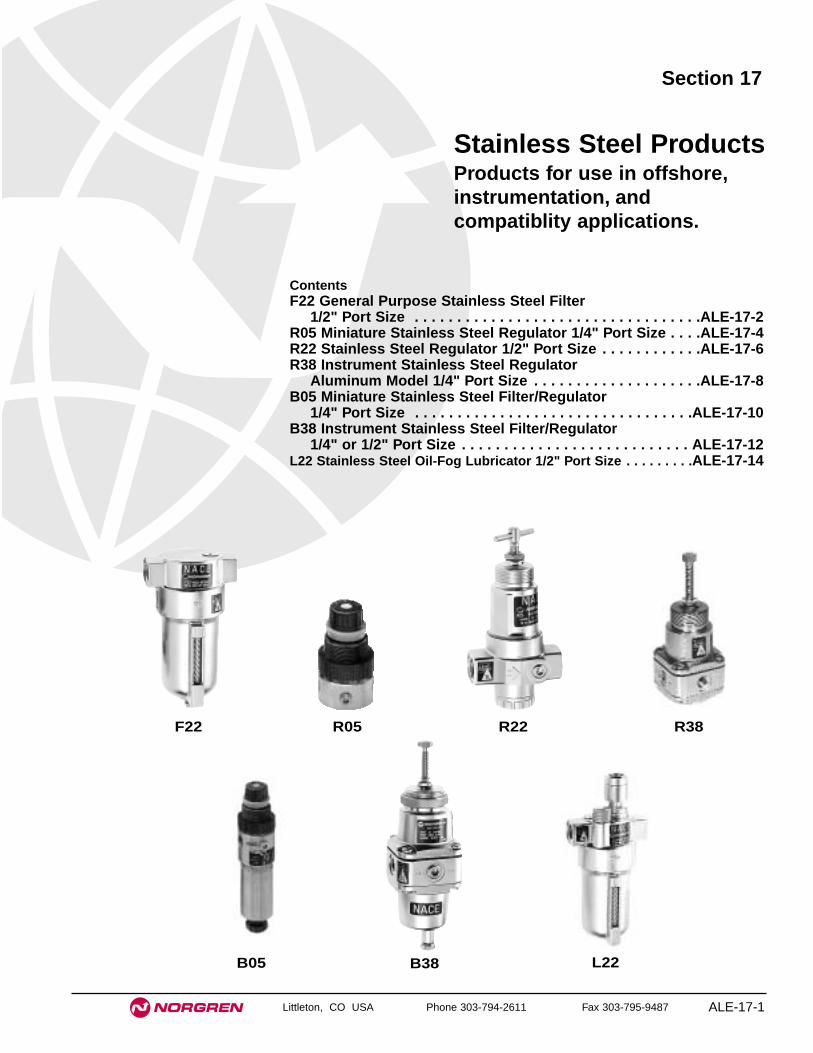
Littleton, CO USA Phone 303-794-2611 Fax 303-795-9487 ALE-17-1
Section 17
ContentsF22 General Purpose Stainless Steel Filter
1/2" Port Size . . . . . . . . . . . . . . . . . . . . . . . . . . . . . . . . . .ALE-17-2R05 Miniature Stainless Steel Regulator 1/4" Port Size . . . .ALE-17-4R22 Stainless Steel Regulator 1/2" Port Size . . . . . . . . . . . .ALE-17-6R38 Instrument Stainless Steel Regulator
Aluminum Model 1/4" Port Size . . . . . . . . . . . . . . . . . . . .ALE-17-8B05 Miniature Stainless Steel Filter/Regulator
1/4" Port Size . . . . . . . . . . . . . . . . . . . . . . . . . . . . . . . . .ALE-17-10B38 Instrument Stainless Steel Filter/Regulator
1/4" or 1/2" Port Size . . . . . . . . . . . . . . . . . . . . . . . . . . . ALE-17-12L22 Stainless Steel Oil-Fog Lubricator 1/2" Port Size . . . . . . . . .ALE-17-14
Stainless Steel ProductsProducts for use in offshore,instrumentation, andcompatiblity applications.
F22 R22 R38
B05 B38 L22
R05
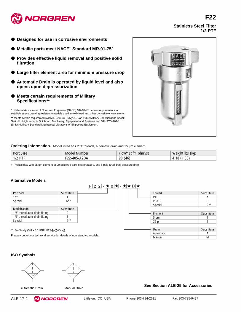
See Section ALE-25 for Accessories
ALE-17-2 Littleton, CO USA Phone 303-794-2611 Fax 303-795-9487
F22
● Designed for use in corrosive environments
● Metallic parts meet NACE† Standard MR-01-75*
● Provides effective liquid removal and positive solidfiltration
● Large filter element area for minimum pressure drop
● Automatic Drain is operated by liquid level and alsoopens upon depressurization
● Meets certain requirements of MilitarySpecifications**
* National Association of Corrosion Engineers (NACE) MR-01-75 defines requirements forsulphide stress cracking resistant materials used in well-head and other corrosive environments.
** Meets certain requirements of MIL-S-901C (Navy) 15 Jan 1963: Military Specifications ShockTest H.I. (High Impact); Shipboard Machinery, Equipment and Systems and MIL-STD-167-1(Ships) Military Standard Mechanical Vibrations of Shipboard Equipment.
Stainless Steel Filter1/2 PTF
ISO Symbols
Automatic Drain Manual Drain
Alternative Models
Port Size Substitute1/2" 4Special 6**
Modification Substitute1/8" thread auto-drain fitting 01/4" thread auto-drain fitting 5Special 7**
Port Size Model Number Flow† scfm (dm3/s) Weight lbs (kg)1/2 PTF F22-405-A2DA 98 (46) 4.18 (1.88)
Ordering Information. Model listed has PTF threads, automatic drain and 25 µm element.
Thread SubstitutePTF AISO G DSpecial S**
22F ★ 0 ★ ★ ★ D ★--
Element Substitute5 µm 125 µm 2
Drain SubstituteAutomatic AManual M
** 3/4" body (3/4 x 16 UNF) F22-6X7-XXXS
Please contact our technical service for details of non standard models.
† Typical flow with 25 µm element at 90 psig (6.3 bar) inlet pressure, and 5 psig (0.35 bar) pressure drop.

ALE-17-3
All Dimensions in Inches (mm)
Littleton, CO USA Phone 303-794-2611 Fax 303-795-9487
F22 Stainless Steel Filters
Technical DataFluid: Compressed airMaximum pressure: 250 psig (17 bar)Operating temperature: 0° to 175°F (-20° to 80°C) ** Air supply must be dry enough to avoid ice formation at temperatures below 35°F (2°C).Particle removal:
25 µm standard5 µm optional
Air quality: Within ISO 8573-1, Class 3 and Class 5 (particulates)Typical flow with 25 µm element at 90 psig (6.3 bar) inlet pressure, and 5 psig
(0.35 bar) pressure droop: 98 scfm (46 dm3/s)Automatic drain connection: Will fit 1/8-27 and 1/8-28 pipe threadAutomatic drain operating conditions (float operated):
Bowl pressure required to close drain: Greater than 5 psig (0.3 bar)Bowl pressure required to open drain: Less than 3 psig (0.2 bar)Minimum air flow required to close drain: 2 scfm (1 dm3/s) Manual operation: Depress pin inside drain outlet to drain bowl
Nominal bowl size: 8 fluid ounce (0.24 liter)Materials
Body: Stainless steelBowl: Stainless steelElement: Sintered stainless steelElastomers: Synthetic rubber
PR
ES
SU
RE
DR
OP 0.6
0.4
0.2
0
bar
d
10
8
6
4
2
0
psi
d
PORT SIZE: 1/2"ELEMENT: 25 µm
2.5(36)
4.0(58)
10.0(150)
6.3(90)
8.0(116)
INLET PRESSURE: psig (bar g)
0 20 40 60 80 100 dm3/sAIR FLOW
0 40 80 120 160 200 scfm
FLOW CHARACTERISTICS
Typical Performance Characteristics
6.77
(17
2)
9.13
(23
2)**
1.34
(34
)
1.14
(38
)
∅1.
50 (
76)
3.90 (99)
0.67
(17
)
6.22
(15
8)
8.58
(21
8)**
0.67
(17
)
**Minimum clearance required to remove bowl
Automatic Drain Manual Drain
Service KitsItem Type Part number
25 µm, automatic drain F22-100A5 µm, automatic drain F22-100A(5)
Service kits25 µm, manual drain F22-100M5 µm, manual drain F22-100M(5)
Replacement drains Automatic 3000-90Manual 2273-18
Service kit Orientable metal bowl 5860-RKService kits include o-rings, gaskets, specified filter elements, drainstrainer and strainer cap.
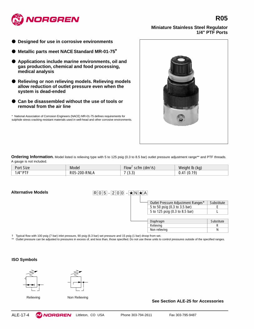
See Section ALE-25 for Accessories
ALE-17-4 Littleton, CO USA Phone 303-794-2611 Fax 303-795-9487
R05
● Designed for use in corrosive environments
● Metallic parts meet NACEStandard MR-01-75*
● Applications include marine environments, oil andgas production, chemical and food processing,medical analysis
● Relieving or non relieving models. Relieving modelsallow reduction of outlet pressure even when thesystem is dead-ended
● Can be disassembled without the use of tools orremoval from the air line
* National Association of Corrosion Engineers (NACE) MR-01-75 defines requirements forsulphide stress cracking resistant materials used in well-head and other corrosive environments.
Miniature Stainless Steel Regulator1/4" PTF Ports
ISO Symbols
Relieving Non Relieving
Alternative Models 50R 2 0 0 ★ N ★ A--
Diaphragm SubstituteRelieving RNon relieving N
Outlet Pressure Adjustment Ranges* Substitute5 to 50 psig (0.3 to 3.5 bar) E5 to 125 psig (0.3 to 8.5 bar) L
Ordering Information. Model listed is relieving type with 5 to 125 psig (0.3 to 8.5 bar) outlet pressure adjustment range** and PTF threads.A gauge is not included.
Port Size Model Flow† scfm (dm3/s) Weight lb (kg)1/4" PTF R05-200-RNLA 7 (3.3) 0.41 (0.19)
† Typical flow with 100 psig (7 bar) inlet pressure, 90 psig (6.3 bar) set pressure and 15 psig (1 bar) droop from set.** Outlet pressure can be adjusted to pressures in excess of, and less than, those specified. Do not use these units to control pressures outside of the specified ranges.

R05 Stainless Steel Regulators
ALE-17-5Littleton, CO USA Phone 303-794-2611 Fax 303-795-9487
Technical DataFluid: Compressed airMaximum pressure: 250 psig (17 bar)Operating temperature: -30° to 150°F (-34° to 66°C) ** Air supply must be dry enough to avoid ice formation at temperatures below 35°F (2°C).Typical flow with 100 psig (7 bar) inlet pressure, 90 psig (6.3 bar) set pressure and
a droop of 15 psig (1 bar) from set: 7 scfm (3.3 dm3/s)Gauge ports:
1/8 PTFMaterials
Body: 316 stainless steelBonnet: Acetal with stainless steel adjusting screwValve: Stainless steel with fluorocarbon elastomerValve seat: AcetalSprings: Stainless steelElastomers: Fluorocarbon
Typical Performance Characteristics
PORT SIZE: 1/4"INLET PRESSURE: 100 psig (7 bar)RANGE: 5 to 125 psig (0.3 to 8.5 bar)
FLOW CHARACTERISTICS
0 2 4 6 8 10 dm3/s
AIR FLOW
0 4 8 12 16 20 24 scfm
8
6
4
2
0
bar
100
80
60
40
20
0
psi
g
120
Panel mounting hole diameter: 1.19" (30 mm)Panel thickness: 25" (6 mm)
1.48 (38)
2.76
(70
)
0.40
(10
)1.
48 (
38)
0.96
(24
)
Service KitsItem Type Part number
Service kitRelieving 3407-71Non relieving 3407-72
Service kit includes slip ring, diaphragm, valve seat with seal,valve, valve spring.
All Dimensions in Inches (mm)

See Section ALE-25 for Accessories
ALE-17-6 Littleton, CO USA Phone 303-794-2611 Fax 303-795-9487
R22
● Designed for use in corrosive environments
● Metallic parts meet NACEStandard MR-01-75*
● Compact instrument units with high performance
● Stable regulation and temperature compensation
● Excellent flow and regulation characteristics
* National Association of Corrosion Engineers (NACE) MR-01-75 defines requirements forsulphide stress cracking resistant materials used in well-head and other corrosive environments.
R22 Stainless Steel Regulator1/2 PTF
ISO Symbols
Relieving Non Relieving
Alternative Models
Port Size Substitute1/2" 4Special** 6
Option SubstituteStandard 0Oxygen degreased 1
Modification SubstituteT-bar adjustment 1Plastic handwheel 5Viton 6Special** 7
Threads SubstitutePTF AISO G DSpecial** S
Port Size Model Number Flow** scfm (dm3/s) Weight lbs (kg)1/2 PTF R22-405-RNMA 106 (50) 3.35 (1.52)
Ordering Information. Models listed have T-bar adjustment, relieving diaphragm, 5 to 150 psig (0.4 to 10 bar) outlet pressure adjustment
range and PTF threads. A gauge is not included.
Outlet Pressure Adjustment Ranges* Substitute5 to 150 psig (0.3 to 10 bar) M5 to 60 psig (0.3 to 4 bar) F10 to 250 psig (0.7 to 17 bar) S
Gauges SubstituteWithout N
22R ★ ★ ★ ★ ★ ★ ★--
Diaphragm SubstituteRelieving RNon relieving N
* Outlet pressure can be adjusted to pressures in excess of, and less than, thosespecified. Do not use these units to control pressures outside of the specified ranges.
** 3/4" body (3/4 x 16 UNF) R22-6X7-XXXS
Please contact our technical service for details of non standard models includingmaximum pressure stop, etc.
** Typical flow with 150 psig (10 bar) inlet pressure, 90 psig (6.3) set pressure, and a 15 psig (1 bar) droop from set.

ALE-17-7
All Dimensions in Inches (mm)
Littleton, CO USA Phone 303-794-2611 Fax 303-795-9487
R22 Stainless Steel Regulators
Technical DataFluid: Compressed airMaximum pressure: 290 psig (20 bar)Operating temperature: -4° to 175°F (-20° to 80°C) ** Air supply must be dry enough to avoid ice formation at temperatures below 35°F
(2°C).Typical flow with 150 psig (10 bar) inlet pressure, 90 psig (6.3 bar) set
pressure and a droop of 15 psig (1 bar) from set: 106 scfm (50 dm3/s)Gauge ports:
1/4 PTFMaterials
Body: Stainless steelBonnet: Stainless steelAdjusting screw: Stainless steelElastomers: Synthetic rubber
Typical Performance Characteristics
INLET PRESSURE - 150 psig (10 bar g)
FLOW CHARACTERISTICS - PORT SIZE: 1/2"
0 20 40 60 80 100 dm3/s
AIR FLOW
0 40 80 120 160 200 240 scfm
OU
TL
ET
PR
ES
SU
RE
8
6
4
2
0
bar
g
100
80
60
40
20
0
psi
g
Panel mounting hole diameter: 1.65" (42 mm)
Maximum Panel thickness: 0.37" (9.5 mm)
∅ 1.57 (40)
7.32
(18
6)
3.19
(81
) m
ax
1.34
(34
)
1.14
(29
)
2.28
(58
)
3.50 (89)
Standard Service KitsItem Type Part number30 psi Relieving R22-100R(2 bar) Non relieving R22-100NR60 psi, 105 psi Relieving R22-101R
(4 bar, 7 bar) Non relieving R22-101NR150 psi Relieving R22-102R
(10 bar) Non relieving R22-102NR
Service kits includes diaphragm assembly, o-ring, valve, valvespring.

See Section ALE-25 for Accessories
ALE-17-8 Littleton, CO USA Phone 303-794-2611 Fax 303-795-9487
R38
● Compact instrument units with high performance
● Stable regulation with temperature compensation
● Excellent flow and regulation characteristics
● Panel Mounting facility
● Designed for use in corrosive environments
● Metallic parts meet NACEStandard MR-01-75*
● Applications include marine environments, oil andgas production, chemical and food processing,medical analysis
● Relieving or non relieving models. Relieving modelsallow reduction of outlet pressure even when thesystem is dead-ended
* National Association of Corrosion Engineers (NACE) MR-01-75 defines requirements forsulphide stress cracking resistant materials used in well-head and other corrosive environments.
Stainless Steel Instrument Regulator 1/4 NPT
ISO Symbol
Port Size Substitute1/4” PTF 2
Materials SubstituteStainless Steel, nitrile elastomers 4Stainless Steel, Viton elastomers 5Stainless Steel, fluorosilicon 6elastomers
Mounting Option SubstituteWithout 0With bracket and nut 1With panel nut only 2With handwheel and nut 3With handwheel, bracket and nut 4With handwheel only 5
Threads SubstitutePTF AISO Rc taper BISO G parallel DAPI.LP.INT K
Outlet Pressure Adjustment Ranges* Substitute0.6 to 30 psig (0.04 to 2 bar) C1 to 60 psig (0.07 to 4 bar) F3.6 to 100 psig (0.25 to 7 bar) K7.2 to 150 psig (0.50 to 10 bar) M
Gauges SubstituteWithout N
83R ★ ★ ★ ★ ★ ★ ★
Diaphragm SubstituteRelieving RNon relieving N
Port Size Model Number Flow† scfm (dm3/s) Weight lbs (kg)1/4" PTF R38-240-RNCA 17 (8) 1.56 (0.71)
Ordering Information. Models listed are relieving type with 0.6 to 30 psig (0.04 to 2 bar) outlet pressure adjustment range **, and PTF
threads. A gauge is not included.
** Outlet pressure can be adjusted to pressures in excess of, and less than, those specified. Do not use these units to control pressures outside ofthe specified ranges.
† Typical flow with 100 psig (7 bar) inlet pressure, 15 psig (1 bar) set pressure and 1 psig (0.05 bar) droop from set.
--

ALE-17-9
All Dimensions in Inches (mm)
Littleton, CO USA Phone 303-794-2611 Fax 303-795-9487
R38 Stainless Steel Regulators
Technical DataFluid: Compressed airMaximum pressure: 451 psig (31 bar)Operating temperature: -40° to 175°F (-40° to 80°C) *
* Air supply must be dry enough to avoid ice formation at temperatures below 35°F (2°C).Typical flow at 100 psig (7 bar) inlet pressure, 15 psig (1 bar) set pressure and a
droop of 1 psig (0.07 bar) from set: 17 scfm (8 dm3/s)Typical relief differential at 30 psig (2 bar) outlet pressure: 2.3 psig (0.16 bar)Maximum bleed flow at 30 psig (2 bar) outlet pressure (relieving types only):
0.003 scfm (1.5 cm3/s)†Gauge ports: 1/4" PTFRelief Port: 1/8" PTFMaterials
Body: Stainless steelBonnet: Stainless steelAdjusting screw: Stainless steelElastomeric materials: Synthetic rubber
† Maximum bleed rate occurs under dead-end (no flow) conditions.
Typical Performance Characteristics
INLET PRESSURE - 100 psig (7 bar g)
FLOW CHARACTERISTICS - PORT SIZE: 1/4"
0 2 4 6 8 10 dm3/s
AIR FLOW
0 4 8 12 16 20 24 scfm
OU
TL
ET
PR
ES
SU
RE
4
3
2
1
0
bar
g
50
40
30
20
10
0
psi
g
REGULATION CHARACTERISTICS - PORT SIZE: 1/4"
OU
TL
ET
PR
ES
SU
RE
4
3
2
1
0
bar
g
0 2 4 6 8 bar gINLET PRESSURE
scfm dm3/s
0 20 40 60 80 100 psig
60
50
40
30
20
10
0
psi
g
7.9 3.7
3.6 1.7
5 2.4
2.5 1.2
MAXIMUM RECOMMENDEDFLOW THROUGH 1/4" PIPE10%
100%200%
100% FLOW
Panel mounting hole diameter: 1.65" (42 mm)Maximum panel thickness: 0.24" (6 mm)
0.51 (13)
2.52 (64)
2.52
(64
)
2.95
(75
)
1.26
(32
)
5.71
(14
5)
2.09
(53
)
1.18
(30
)
∅ 1.65 (42)
Service KitsItem Type Part number
30 psig (2 bar) rangeRelieving R38-100-RNon relieving R38-100-NR
60 & 100 psig Relieving R38-101-R(4 & 7 bar) range Non relieving R38-101-NR
Service kits includes diaphragm assembly, o-ring, valve, valvespring and 8 pan head screws.

See Section ALE-25 for Accessories
ALE-17-10 Littleton, CO USA Phone 303-794-2611 Fax 303-795-9487
B05
● Designed to filter and regulate compressed air incorrosive environments
● Metallic parts meet NACEStandard MR-01-75*
● Applications include marine environments, oil andgas production, chemical and food processing,medical analysis
● Relieving or non relieving models. Relieving modelsallow reduction of outlet pressure even when thesystem is dead-ended
● Can be disassembled without the use of tools orremoval from the air line
* National Association of Corrosion Engineers (NACE) MR-01-75 defines requirements forsulphide stress cracking resistant materials used in well-head and other corrosiveenvironments.
Miniature Stainless Steel Filter/Regulator1/4 PTF Ports
Automatic Drain, Non-Relieving
Manual Drain, Non-Relieving
ISO Symbols
Automatic Drain, Relieving
Manual Drain, Relieving
Ordering Information. Model listed includes a relieving diaphragm, manual drain, 40 µm element, 5 to 125 psig (0.3 to 8.5 bar) outlet
pressure adjustment range** and PTF threads. A gauge is not included.
Port Size Model Flow† scfm (dm3/s) Weight lb (kg)1/4 PTF B05-233-M2LA 7 (3.3) 0.99 (0.45)
** Outlet pressure can be adjusted to pressures in excess of, and less than, those specified. Do not use these units to control pressures outside of the specified ranges.† Typical flow with 100 psig (7 bar) inlet pressure, 90 psig (6.3 bar) set pressure and 15 psig (1 bar) droop from set.
Alternative Models - ★★★ ★★ ★ -0 ★B 5
Threads SubstitutePTF A
Drain SubstituteAutomatic AManual M
Port Size Substitute1/4" 2
Element Substitute5 µm 140 µm 2
Outlet Pressure Adjustment Ranges* Substitute5 to 50 psig (0.3 to 3.5 bar) E5 to 125 psig (0.3 to 8.5 bar) L
Diaphragm SubstituteRelieving 33Non relieving 35

B05 Stainless Steel Filter/Regulators
ALE-17-11
All Dimensions in Inches (mm)
Littleton, CO USA Phone 303-794-2611 Fax 303-795-9487
Technical DataFluid: Compressed airMaximum pressure: 250 psig (17 bar)Operating temperature: -30° to 150°F (-34° to 66°C) ** Air supply must be dry enough to avoid ice formation at temperatures below 35°F (2°C)
Particle removal: 5 µm or 40 µm filter elementAir quality: Within ISO 8573-1, Class 3 and Class 5 (particulates)Typical flow with 100 psig (7 bar) inlet pressure, 90 psig (6.3 bar) set pressure and
a droop of 15 psig (1 bar) from set: 7 scfm (3.3 dm3/s)Nominal bowl size: 1 fluid ounce (31 ml)Gauge ports: 1/8 PTFAutomatic drain connection: Will fit 1/8-27 and 1/8-28 pipe thread.Automatic drain operation: Spitter type drain operates momentarily when a rapid
change in air flow occurs or when the supply pressure is reduced.Materials
Body and bowl: 316 stainless steelBonnet: Acetal with stainless steel adjusting screwValve: Stainless steel with fluorocarbon elastomerValve seat: AcetalSprings: Stainless steelDrain: AcetalElement: Sintered polypropyleneElastomers: Fluorocarbon
Typical Performance Characteristics
PORT SIZE: 1/4"INLET PRESSURE: 100 psig (7 bar)RANGE: 5 to 125 psig (0.3 to 8.5 bar)
FLOW CHARACTERISTICS
0 2 4 6 8 10 dm3/s
AIR FLOW
0 4 8 12 16 20 24 scfm
OU
TL
ET
PR
ES
SU
RE
8
6
4
2
0
bar
100
80
60
40
20
0
psi
g
120
Panel mounting hole diameter: 1.19" (30 mm)Panel thickness: 25" (6 mm)
ø 1.48 (38)
4.09
(10
4)
1.03
(26)
Manual Drain
5.28
(134
) **
2.36
(60
)
Automatic Drain
5.09
(129
)**
3.9
(99)
** Minimum clearance required to remove bowl.
Service KitsItem Type Part number
Service kitRelieving 3820-08Non relieving 3820-09
Drain Manual 684-51
Service kit includes diaphragm, seals, o-rings, and valve.

See Section ALE-25 for Accessories
ALE-17-12 Littleton, CO USA Phone 303-794-2611 Fax 303-795-9487
B38
● Compact instrument units with high performance
● Stable regulation with temperature compensation
● Excellent flow and regulation characteristics
● Panel Mounting facility
● Designed for use in corrosive environments
● Metallic parts meet NACEStandard MR-01-75*
● Applications include marine environments, oil andgas production, chemical and food processing,medical analysis
● Relieving or non relieving models. Relieving modelsallow reduction of outlet pressure even when thesystem is dead-ended
* National Association of Corrosion Engineers (NACE) MR-01-75 defines requirements forsulphide stress cracking resistant materials used in well-head and other corrosive environments.
Filter/Regulator Stainless Steel Model1/4 or 1/2” PTF
ISO Symbols
Automatic Drain, Relieving Automatic Drain, Non RelievingManual Drain, Relieving Manual Drain, Non Relieving
Outlet pressure rangePort Size Model Number psig (bar) Flow** scfm (dm3/s) Weight kg (lbs)1/4” PTF B38-240-B1KA 4 to 100 (0.3 to 7) 15 (7) 3.11 (1.4)1/2” PTF B38-440-M1LA 4 to 125 (0.3 to 9) 106 (50) 4.75 (2.2)
Ordering Information. Models listed are relieving type with manual drain, 5µm element, and PTF threads. A gauge is not included.
** Typical flow with 175 psig (12 bar) inlet pressure, 115 psig (8 bar) set pressure and 15 psig (1 bar) droop from set.
Alternative Models
Port Size Substitute1/4” PTF 21/2” PTF 4
Materials SubstituteStainless steel, nitrile elastomers 4Stainless steel, Viton elastomers 5 †
Threads SubstitutePTF AISO Rc taper BISO G parallel DAPI.LP.INT K
Outlet Pressure Adjustment Ranges* Substitute0.6 to 30 psig (0.04 to 2 bar) C 1 to 60 psig (0.07 to 4 bar) F 3.6 to 100 psig (0.25 to 7 bar) K †4 to 125 psig (0.3 to 9 bar) L ††7.2 to 150 psig (0.5 to 10 bar) M †10 to 250 psig (0.7 to 17 bar) S ††
Element Substitute5 µm 125 µm 2
Bowl/Drain SubstituteLong bowl with automatic drain AShort bowl with manual drain BLong bowl with manual drain M
* Outlet pressure can be adjusted to pressures in excess of, and less than, those specified.Do not use these units to control pressures outside of the specified ranges.
† 1/4” ported units only.†† 1/2” ported units only.
83B ★ ★ ★ ★ ★ ★ ★--
Diaphragm SubstituteRelieving 0Non relieving 1Relieving, bracket and nut 2Non relieving, bracket and nut 3Relieving with nut 4Non relieving with nut 5Relieving with handwheel and nut 6Non relieving with handwheel and nut 7Relieving with handwheel, bracket and nut 8Non relieving with handwheel, bracket and nut 9

B38 Stainless Steel Filter/Regulator
ALE-17-13
All Dimensions in Inches (mm)
Littleton, CO USA Phone 303-794-2611 Fax 303-795-9487
Technical DataFluid: Compressed airMaximum pressure
Manual drain: 450 psig (31 bar)Automatic drain: 250 psig (17 bar)
Operating temperature: -40° to 175°F (-40° to 80°C) ** Air supply must be dry enough to avoid ice formation at temperatures below 35°F (2°C).Particle removal: 5 µm or 25 µm filter elementAir quality: Within ISO 8573-1, Class 3 and Class 5 (particulates)Typical flow with 175 psig (12 bar) inlet pressure, 115 psig (8 bar) set pressure and
a droop of 15 psig (1.0 bar) from set1/4": 15 scfm (7 dm3/s)1/2": 106 scfm (50 dm3/s)
Automatic drain connection: Will fit 1/8-27 and 1/8-28 pipe threadAutomatic drain operating conditions (float operated)
Bowl pressure required to close drain: Greater than 5 psig (0.3 bar)Bowl pressure required to open drain: Less than 3 psig (0.2 bar)Minimum air flow required to close drain 2 scfm (1 dm3/s)
Nominal bowl sizeShort bowl with manual drain: 25 ml (1 fluid ounce)Long bowl with manual drain: 3 fluid ounce (90 ml)Long bowl with automatic drain: 1 fluid ounce (25 ml)
Gauge ports:1/4" PTF
Relief port:1/8" PTF
Materials (standard option)Body: Stainless steelBonnet: Stainless steelBowl: Stainless steelAdjusting screw: Stainless steelElements
5 µm & 25 µm: High density polyethylene1/4" only 5 µm: Ceramic pyrolith
Elastomeric materials: Synthetic rubber
Typical Performance Characteristics
INLET PRESSURE - 175 psig (12 bar g)
FLOW CHARACTERISTICS - PORT SIZE: 1/2"
0 20 40 60 80 100 dm3/s
AIR FLOW
0 40 80 120 160 200 240 scfm
OU
TL
ET
PR
ES
SU
RE
16
12
8
4
0
bar
g
200
160
120
80
40
0 p
sig
INLET PRESSURE - 175 psig (12 bar g)
FLOW CHARACTERISTICS - PORT SIZE: 1/4"
0 4 8 12 16 20 dm3/s
AIR FLOW
0 8 16 24 32 40 48 scfm
OU
TL
ET
PR
ES
SU
RE
16
12
8
4
0
bar
g
200
160
120
80
40
0
psi
g
0.51 (13)
2.52 (64)
2.52
(64
)
2.95
(75
)
(1.2
6 (3
2)
5.71
(19
4)
2.09
(53
)3.
23 (
82)
∅ 1.65 (42)
9.61
(24
4)
2.09
(53
)5.
20 (
132)
∅ 1.65 (42)
5.32
(13
5)**
7.28
(18
5)**
1/8" PTF
0.51 (13)
2.88 (73)
2.52
(64
)
2.95
(75
)
1.26
(32
)
11.1
4 (2
83)
2.37
(62
)6.
38 (
162)
∅ 1.65 (42)
8.47
(21
5)**
10.7
5 (2
73)
2.37
(62
)5.
98 (
152)
∅ 1.65 (42)
8.01
(20
5)**
** Minimum clearance required to remove bowl.
1/4” Port SizeManual Drain, Short Bowl
1/4” Port SizeAutomatic Drain, Long Bowl
1/2” Port SizeManual Drain, Long Bowl 1/2” Port Size
Automatic Drain, Long Bowl
Panel mounting hole diameter: 1.65" (42 mm)Maximum panel thickness: 0.24" (6 mm)
Service Kits (standard option)
1/4" Regulator
1/2" Regulator
Item Type Part number
30 psig spring Relieving R38-100R Non relieving R38-100NR
60 & 100 psig Relieving R38-101R spring Non relieving R38-101NR
150 psig spring Relieving R38-102R Non relieving R38-102NR
Item Type Part numberAll available Relieving 2787-41spring ranges Non relieving 2787-42
Item Part number5 µm B38-100S (5)25 µm B38-100S (25)
Item Part number5 µm 2787-4325 µm 2787-44
Automatic Drain Assembly
Item Part numberAutomatic Drain Assembly 3000-90
Filter service kits include element, seals and screws.
Regulator service kits include diaphragm assembly, o-ring,valve, valve spring and 8 pan head screws.
1/4" Filter
1/2" Filter

See Section ALE-25 for Accessories
Littleton, CO USA Phone 303-794-2611 Fax 303-795-9487
L22
● Metallic parts meet NACEStandard MR-01-75*
● Low flow start point
● Built-in flow sensor gives almost constant oil/air ratioover a wide range of flows
● Can be filled under pressure
● Simple and accurate drip rate adjustment
● Ideal for general lubrication applications
● Meets certain requirements of MilitarySpecifications**
* National Association of Corrosion Engineers (NACE) MR-01-75 defines requirements forsulphide stress cracking resistant materials used in well-head and other corrosive environments.
** Meets certain requirements of MIL-S-901C (Navy) 15 Jan 1963: Military Specifications ShockTest H.I. (High Impact); Shipboard Machinery, Equipment and Systems and MIL-STD-167-1(Ships) Military Standard Mechanical Vibrations of Shipboard Equipment.
L22 Stainless Steel Oil-Fog Lubricator1/2 PTF
ALE-17-14
22L ★ 0 ★ O P ★ ★--Alternative Models
Port Size Substitute1/2" 4Special 6**
Modification SubstituteClosed bowl 0Plugged closed bowl 5Special 7*
Thread SubstitutePTF AISO G DSpecial S*
Bowl SubstituteClosed bowl 8Manual drain D
** 3/4" body (3/4 x 16 UNF) L22-6X7-OPXS
Type Model Number Flow† scfm (dm3/s) Weight lbs (kg)Oil-Fog L22-405-OP8A 102 scfm (48 dm3/s) 4.29 (1.93)
Ordering Information. Models listed are oil-fog units with closed bowl (no drain) and PTF threads.
ISO Symbols
No Drain With Drain
†Typical flow with 90 psig (6.3 bar) inlet pressure and 7 psig (0.5 bar) pressure drop.
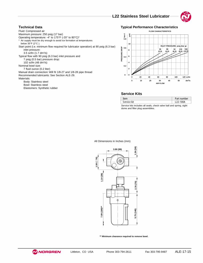
L22 Stainless Steel Lubricator
Littleton, CO USA Phone 303-794-2611 Fax 303-795-9487 ALE-17-15
All Dimensions in Inches (mm)
Typical Performance CharacteristicsTechnical DataFluid: Compressed airMaximum pressure: 250 psig (17 bar)Operating temperature: -4° to 175°F (-20° to 80°C)** Air supply must be dry enough to avoid ice formation at temperatures
below 35°F (2°C ).Start point (i.e. minimum flow required for lubricator operation) at 90 psig (6.3 bar)
inlet pressure:3.5 scfm (1.7 dm3/s)
Typical flow with 90 psig (6.3 bar) inlet pressure and 7 psig (0.5 bar) pressure drop:102 scfm (48 dm3/s)
Nominal bowl size:7 fluid ounce (0.2 liter)
Manual drain connection: Will fit 1/8-27 and 1/8-28 pipe threadRecommended lubricants: See Section ALE-29.Materials:
Body: Stainless steelBowl: Stainless steelElastomers: Synthetic rubber
5.75
(14
6)
7.09
(18
0)**
1.34
(34
)
1.14
(38
)
1.50
(∅
76)
3.90 (99)
2.76
(70
)
** Minimum clearance required to remove bowl.
Service KitsItem Part numberService kit L22-100A
Service kits includes all seals, check valve ball and spring, sightdome and filter plug assemblies.
INLET PRESSURE: psig (bar g)
FLOW CHARACTERISTICS
0 10 20 30 40 50 dm3/s
AIR FLOW
0 20 40 60 80 100 120 scfm
PR
ES
SU
RE
DR
OP
0.8
0.6
0.4
0.2
0
bar
d
10
8
6
4
2
0
psi
d
36(2.5)
58(4.0)
91(6.3)
116(8.0)
150(10.0)


Littleton, CO USA Phone 303-794-2611 Fax 303-795-9487 ALE-18-1
Section 18
ValvesSmooth Start, Soft Start/Exhaust,Directional Control, Directional Controlwith Lockout 1/4" to 1-1/2" Port Sizes
P72CP72F
P72E P74EP74F
P74 Air Operated
P74 Solenoid Operated
P74 Solenoid w/lockout
P64 Soft Start/Dump
Smooth Start ValvesP72E (1/4", 3/8" threaded ports in valve body) . . . . . . . . . . . . . . . . . . . . .ALE-18-2P74E Quikclamp Mounted (1/4", 3/8", 1/2", 3/4"
threaded ports in Quikclamp pipe adapter) . . . . . . . . . . . . . . . . . . . . . .ALE-18-4Smooth Start/Exhaust Valves
P72F (1/4", 3/8" threaded ports in valve body) . . . . . . . . . . . . . . . . . . . . .ALE-18-6P74F (3/8", 1/2", 3/4" threaded ports in valve body) . . . . . . . . . . . . . . . . .ALE-18-8P64F Yoke Mounted (1/4", 3/8", 1/2", 3/4" ports in yoke) . . . . . . . . . . . . .ALE-18-10P68F Yoke Mounted (3/4", 1", 1-1/4", 1-1/2" ports in yoke) . . . . . . . . . . .ALE-18-12
Directional Control ValvesP72C (air and solenoid operated, 3-way valve,
1/4", 3/8" threaded ports in valve body . . . . . . . . . . . . . . . . . . . . . . . . .ALE-18-14P74 Quikclamp Mounted (air operated, 2 and 3-way valves,
1/4", 3/8", 1/2", 3/4" threaded ports in Quikclamp pipe adapter) . . . . . .ALE-18-16P74 Quikclamp Mounted (solenoid operated, 2 and 3-way valves,
1/4", 3/8", 1/2", 3/4" threaded ports in Quikclamp pipe adapter) . . . . . .ALE-18-18Directional Control Valve with Lockout Slide
P74 Quikclamp Mounted (solendoid operated, 3-way valves, 1/4", 3/8", 1/2", 3/4" threaded ports in Quikclamp pipe adapter . . . . . . .ALE-18-20
FAQ’s . . . . . . . . . . . . . . . . . . . . . . . . . . . . . . . . . . . . . . . . . . . . . . . . . . . .ALE-18-22
P68F Smooth Start/Exhaust Valve
Product available1st quarter of 2001

See Section ALE-25 for Accessories
Littleton, CO USA Phone 303-794-2611 Fax 303-795-9487
P72E
● Excelon design allows in-line or modular installation
● High-flow, spring return, 2 port/2 position normallyclosed valves
● Reduces rate of downstream air pressure buildup atsystem start up
● Cylinders and other air operated devices are easedinto normal starting positions, reducing thepossibility of equipment damage and hazards to theuser.
● Adjustable rate of pressure increase
● Cushioned poppets for long service life
● Modular installations with Excelon 72, 73, and 74series can be made to suit particular applications
Excelon 72 Smooth Start Valves1/4", 3/8" Port Sizes
ALE-18-2
ISO Symbol
Ordering Information. Models listed are with PTF threads.
Port Size Model Weight lb (kg)1/4" P72E-2AN-NNN 1.86 (0.84)3/8" P72E-3AN-NNN 1.80 (0.82)
P 7 2 -E ★ ★ - NN N NAlternative Models
Port Size Substitute1/4" 23/8" 3
Threads SubstitutePTF AISO Rc taper BISO G taper G

P72E Smooth Start Valve
Littleton, CO USA Phone 303-794-2611 Fax 303-795-9487 ALE-18-3
All Dimensions in Inches (mm)
Technical DataFluid: Compressed airMaximum pressure: 250 psig (17 bar)Minimum operating pressure: 44 psig (3 bar)Temperature range*: -0° to 150°F (-20° to 65°C)
* Air supply must be dry enough to avoid ice formaton at temperatures below 35°F (2°C).Ports:
PTF portsISO G portsISO Rc ports
Maximum flow with 90 psig (6.3 bar) inlet pressure and pressure drop of 7 psig(0.5 bar): 45 scfm (21 dm3/s)
Snap pressure:Full flow when downstream pressure reaches 50 – 80% of inlet pressure
Charge time:For 0.53 gallon US (2 liter) downstream volume and 90 psig (6.3 bar) inletpressure 0.8 sec. minimum76 sec. maximum
Average flow factor (Cv): 1.35Materials
Body: Zinc alloyElastomers: Synthetic materialsInternal components: Brass/steel
Note: Smooth start valves never shut off completely, and must be installeddownstream of a directional control valve such as a Norgren Poppet or LockoutValve.
Ordering Information
INLET PRESSURE: psig (bar g)
FLOW CHARACTERISTICS
0 5 10 15 20 25 dm3/s
AIR FLOW
0 10 20 30 40 50 60 scfm
PR
ES
SU
RE
DR
OP
0.8
0.6
0.4
0.2
0
bar
d
10
8
6
4
2
0
psi
d
44(3)
91(6.3)
58(4.0)
150(10)
116(8)
PORT SIZE: 1/4"
0.53 gal (2 liter) downstream volume
SNAP POINT
PERCENTAGE SNAP POINT
0 20 40 60 80 100 120
CHARGE TIME - (S)
OU
TL
ET
PR
ES
SU
RE
16
12
8
4
0
bar
g
200
160
120
80
40
0 p
sig
2.60 (66)
0.95
(24
)
1.89
(48
)
1.77
(45
)
3.58
(91
)

See Section ALE-25 for Accessories
Littleton, CO USA Phone 303-794-2611 Fax 303-795-9487
P74E
● Modular installation only
● High-flow, spring return, 2-port/2-position normallyclosed valves.
● Reduces rate of downstream air pressure buildup atsystem start up
● Cylinders and other air operated devices are easedinto normal starting positions, reducing thepossibility of equipment damage and hazards to theuser.
● Adjustable rate of pressure increase
● Cushioned poppets for long service life
Excelon 74 Smooth Start ValvesUnthreaded Ports, 1/2" Basic Size
ALE-18-4
ISO Symbol
Ordering Information
* Valve ports are unthreaded. To install in air line use Quikclamp™ and Quikclamp pipe adapters or connect to other Excelon 74 units.
Installation Type 2 Port/2 Position Weight lb (kg)Normally Closed
Modular P74E-NNN-NNN 1.17 (0.53)

P74E Smooth Start Valves
Littleton, CO USA Phone 303-794-2611 Fax 303-795-9487 ALE-18-5
All Dimensions in Inches (mm)
Technical DataFluid: Filtered and lubricated compressed airInlet pressure range: 30 to 250 psig (2 to 17 bar)Temperature range*: -20° to 175°F (-30° to 80°C) * Air supply must be dry enough to avoid ice formation at temperatures below 35°F (2°C).Time delay: Application of full downstream pressure can be delayed for as long as
50 seconds, depending on the setting of the adjustable needle valve anddownstream air volume.
Average flow factor (Cv): 4.0Materials:
Body: ZincPistons, poppets: AluminumElastomers: Nitrile
Note: Smooth start valves never shut off completely, and must be installeddownstream of a directional control valve such as a Norgren Poppet orLockout Valve.
Item Type Part NumberService kit Seal & Gasket 53474-37Quikclamp service kit 2 o-rings 4384-770
Service Kit
Service kit includes all o-rings, head gasket and seals.
3.15 (80)
3.75
(95
) 1.45
(37
)
2.28
(58
)
3.60 (91)
Modular Components (necessary for using this valve)
Quikmount Pipe Adapters (each kit contains one adapter) **Size PTF Threads ISO Rc Threads ISO G Threads1/4" 4315-01 4315-05 4315-093/8" 4315-01 4315-06 4315-101/2" 4315-03 4315-07 4315-11 Quikclamp †
3/4" 4315-04 4315-08 4315-12 4314-51
** Each pipe adapter adds 0.71" (18 mm) to the overall length of a valve.† Each Quikclamp adds 0.7" (13.6 mm) to the overall length of a valve.

See Section ALE-25 for Accessories
Littleton, CO USA Phone 303-794-2611 Fax 303-795-9487
P72F
● Excelon design allows in-line or modular installation
● Controls increase of downstream pressure onstart up. Cylinders and other air operated devices areeased into normal operating positions, reducing thepossibility of equipment damage and hazards to theuser.
● 3 port/2 position, normally closed, soft start valvewith optional manual lockout slide
● Blocks inlet air and exhausts downstream air whenpilot signal is removed or when the optional manuallockout slide is closed
● Optional manual slide can be padlocked in closedposition
● Solenoid pilot or air pilot operation
● Designed primarily for use in start-up and shutdownof equipment, not as a frequently cycling directionalcontrol valve. Norgren offers a wide variety of valvesdesigned for frequent cycling and other applications.Please refer to the P72C and P74C valves, and toother Norgren valve catalogs.
Excelon 72 Smooth Start/Exhaust Valve 1/4", 3/8" Port Sizes
ALE-18-6
ISO Symbols
Solenoid operated Air pilot
Ordering Information. Models listed are with PTF threads. Solenoid operated models include 24 VDC coil and plug without indicator.
* To select other solenoid type and coil voltage refer to alternative models table below.
Port Size Solenoid Operated* Weight Air Pilot Operated Weight Model lb (kg) Model lb (kg)
1/4" P72F-2AC-PFA 2.00 (0.91) P72F-2AA-NNN 1.93 (0.88)3/8" P72F-3AC-PFA 1.98 (0.90) P72F-3AA-NNN 1.91 (0.87)
P 7 2 -F ★ ★ - ★★ ★ ★
Solenoid Manual Operator SubstituteShrouded push button PNone N
Connectors Substitute3 pin plug with cable gland, Ano indicatorWithout N
** to order air pilot models also substitute ‘NNN’ atdigits 8, 9 and 10 e.g. P72F-2GA-NNN.
Alternative Models
Coil Voltage Nominal SubstitutePower Rating
24 V d.c. 2 W F12 V d.c. 2 W E6 V d.c. 2 W D220/240 V 4/2.5 VA B50/60 Hz110/120 V 4/2.5 VA A50/60 HzNo coil 2 W ZNo solenoid N
Operator SubstituteAir pilot** A22 mm miniature solenoid CCNOMO L
Threads SubstitutePTF AISO Rc taper BISO G parallel G
Port Size Substitute1/4" 23/8" 3

P72F Smooth Start/Exhaust Valve
Littleton, CO USA Phone 303-794-2611 Fax 303-795-9487 ALE-18-7
All Dimensions in Inches (mm)
Technical DataSystem air supply: Turn on system air supply prior to applying pilot signal to operator. Failure to
do so may cause valve to continuously exhaust.
Fluid: Compressed airMaximum pressure solenoid operated:
Dependant on solenoid rating [must not exceed 250 psig (17 bar)]
Maximum pressure pilot operated: 250 psig (17 bar) max.Minimum operating pressure: 44 psig (3 bar)Operating temperature solenoid operated:
Dependant on solenoid rating [must be within range 0°* to 150°F (-20°* to 65°C)]
Operating temperature pilot operated:0°* to 150°F (-20°* to 65°C)
* Air supply must be dry enough to avoid ice formation at temperatures below 35°F (2°C).Air Pilot Port:
10-32 UNF with PTF main portsM5 with ISO main ports
Exhaust Port:1/4" PTF with PTF main ports1/4" ISO Rc with ISO Rc main ports1/4" ISO Rc with ISO G main ports
Maximum flow with 90 psig (6.3 bar) inlet pressure and pressure drop of 7 psig(0.5 bar): 45 scfm (21 dm3/s) [P1 to P2 = Cv 1.59] [P2 to P3 = Cv 1.72]
Snap pressure:Full flow when downstream pressure reaches 50 – 80% of inlet pressure
Charge time:For 0.53 gallon US (2 liter) downstream volume and 90 psig (6.3 bar) inletpressure Minimum 0.8 sec.Typical maximum 99 sec.
MaterialsBody: Zinc alloyElastomers: Synthetic materialsFilter discs: Sintered plasticInternal components: Brass/steel
Typical Performance Characteristics
0.53 gal (2 liter) downstream volume
SNAP POINT
PERCENTAGE SNAP POINT
0 20 40 60 80 100 120
CHARGE TIME - (S)
OU
TL
ET
PR
ES
SU
RE
16
12
8
4
0
bar
g
200
160
120
80
40
0 p
sig
INLET PRESSURE: psig (bar g)
FLOW CHARACTERISTICS
0 5 10 15 20 25 dm3/s
0 10 20 30 40 50 60 scfm
PR
ES
SU
RE
DR
OP
0.8
0.6
0.4
0.2
0
bar
d
10
8
6
4
2
0
psi
d
44(3)
91(6.3)
58(4.0)
150(10)
116(8)
PORT SIZE: 1/4"
2.60 (66)
0.95
(24
)
1.89
(48
)
4.57
(11
6)
6.38
(16
2)
1/4" exhaust port
2.60 (66)
0.95
(24
)
1.89
(48
)
1.77
(45
)
3.58
(91
)
Pilot port
1/4" exhaust port
Solenoid operated
Air pilot operated

See Section ALE-25 for Accessories
Littleton, CO USA Phone 303-794-2611 Fax 303-795-9487
P74F
● Excelon design allows in-line or modular installation
● Controls increase of downstream pressure onstart up. Cylinders and other air operated devices areeased into normal operating positions, reducing thepossibility of equipment damage and hazards to theuser.
● 3 port/2 position, normally closed, soft start valvewith optional manual lockout slide
● Blocks inlet air and exhausts downstream air whenpilot signal is removed or when the optional manuallockout slide is closed
● Optional manual slide can be padlocked in closedposition
● Solenoid pilot or air pilot operation
● Designed primarily for use in start-up and shutdownof equipment, not as a frequently cycling directionalcontrol valve. Norgren offers a wide variety of valvesdesigned for frequent cycling and other applications.Please refer to the P72C and P74C valves, and toother Norgren valve catalogs.
Excelon 74 Smooth Start/Exhaust Valve3/8", 1/2", 3/4" Port Size
ALE-18-8
ISO Symbols
Solenoid operated Air pilot
P 7 4 -F ★ ★ - ★★ ★ ★
Solenoid Manual Operator SubstituteShrouded push button PNone N
Connectors Substitute3 pin plug with cable gland, Ano indicatorWithout N
** To order air pilot models also substitute ‘NNN’ atdigits 8, 9 and 10 e.g. P74F-4AA-NNN.
Alternative Models
Coil Voltage Nominal SubstitutePower Rating
24 V d.c. 2 W F12 V d.c. 2 W E6 V d.c. 2 W D220/240 V 4/2.5 VA B50/60 Hz110/120 V 4/2.5 VA A50/60 HzNo coil 2 W ZNo solenoid N
Port Size Substitute3/8" 31/2" 43/4" 6
Threads SubstitutePTF AISO Rc taper BISO G parallel G
Operator SubstituteAir pilot** AAir pilot with manual lockout slide** B22 mm miniature solenoid C22 mm miniature solenoid with manual lockout slide DCNOMO solenoid LCNOMO solenoid with manual lockout slide M
Port Size Solenoid Operated* Weight Air Pilot Operated WeightModel lb (kg) Model lb (kg)
3⁄8" P74F-3AC-PFA 2.4 (1.08) P74F-3AA-NNN 2.3 (1.05)1⁄2" P74F-4AC-PFA 2.3 (1.05) P74F-4AA-NNN 2.2 (1.02)3⁄4" P74F-6AC-PFA 3.1 (1.41) P74F-6AA-NNN 3.0 (1.35)
* To select other solenoid type and coil voltage refer to alternative models table below.
Ordering Information. Models listed are with PTF ports. Solenoid operated models include 24 V d.c. coil and plug without indicator.
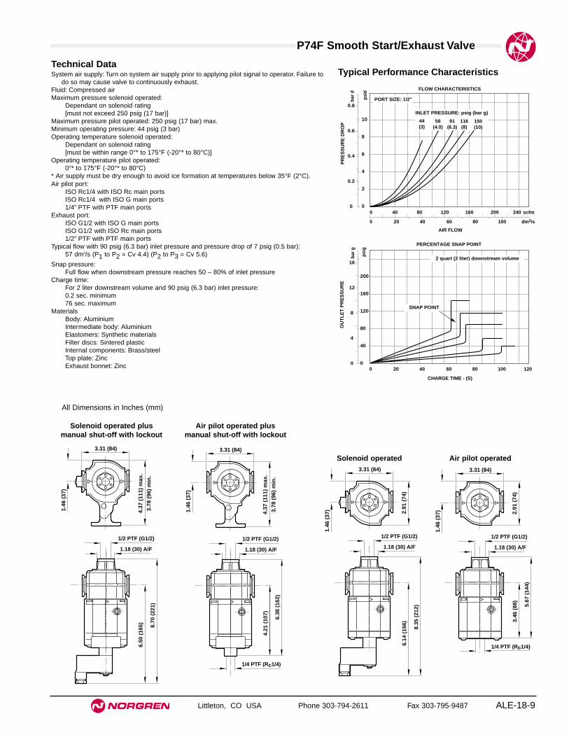
P74F Smooth Start/Exhaust Valve
Littleton, CO USA Phone 303-794-2611 Fax 303-795-9487 ALE-18-9
All Dimensions in Inches (mm)
Technical DataSystem air supply: Turn on system air supply prior to applying pilot signal to operator. Failure to
do so may cause valve to continuously exhaust.Fluid: Compressed airMaximum pressure solenoid operated:
Dependant on solenoid rating [must not exceed 250 psig (17 bar)]
Maximum pressure pilot operated: 250 psig (17 bar) max.Minimum operating pressure: 44 psig (3 bar)Operating temperature solenoid operated:
Dependant on solenoid rating [must be within range 0°* to 175°F (-20°* to 80°C)]
Operating temperature pilot operated:0°* to 175°F (-20°* to 80°C)
* Air supply must be dry enough to avoid ice formation at temperatures below 35°F (2°C).Air pilot port:
ISO Rc1/4 with ISO Rc main portsISO Rc1/4 with ISO G main ports1/4” PTF with PTF main ports
Exhaust port:ISO G1/2 with ISO G main portsISO G1/2 with ISO Rc main ports1/2” PTF with PTF main ports
Typical flow with 90 psig (6.3 bar) inlet pressure and pressure drop of 7 psig (0.5 bar):57 dm3/s (P1 to P2 = Cv 4.4) (P2 to P3 = Cv 5.6)
Snap pressure:Full flow when downstream pressure reaches 50 – 80% of inlet pressure
Charge time:For 2 liter downstream volume and 90 psig (6.3 bar) inlet pressure:0.2 sec. minimum76 sec. maximum
MaterialsBody: AluminiumIntermediate body: Aluminium Elastomers: Synthetic materialsFilter discs: Sintered plasticInternal components: Brass/steelTop plate: ZincExhaust bonnet: Zinc
Typical Performance Characteristics
INLET PRESSURE: psig (bar g)
FLOW CHARACTERISTICS
0 20 40 60 80 100 dm3/s
AIR FLOW
0 40 80 120 160 200 240 scfm
0.8
0.6
0.4
0.2
0
PR
ES
SU
RE
DR
OP
bar
d
10
8
6
4
2
0
psi
d
PORT SIZE: 1/2"
44(3)
91(6.3)
58(4.0)
116(8)
150(10)
2 quart (2 liter) downstream volume
PERCENTAGE SNAP POINT
0 20 40 60 80 100 120
CHARGE TIME - (S)
16
12
8
4
0
OU
TL
ET
PR
ES
SU
RE
bar
g
200
160
120
80
40
0 p
sig
SNAP POINT
8.35
(21
2)
6.14
(15
6)
1/2 PTF (G1/2)
1.18 (30) A/F
3.31 (84)
2.91
(74
)
1.46
(37
)
1/2 PTF (G1/2)
1.18 (30) A/F
5.67
(14
4)
3.46
(88
)
1/4 PTF (Rc1/4)
3.31 (84)
2.91
(74
)
1.46
(37
)
8.70
(22
1)
6.50
(16
5)
3.31 (84)
4.37
(11
1) m
ax.
3.78
(96
) m
in.
1.46
(37
)
1/2 PTF (G1/2)
1.18 (30) A/F
6.38
(16
2)
4.21
(10
7)
1/4 PTF (Rc1/4)
3.31 (84)
4.37
(11
1) m
ax.
3.78
(96
) m
in.
1.46
(37
)
1/2 PTF (G1/2)
1.18 (30) A/F
Solenoid operated
Solenoid operated plusmanual shut-off with lockout
Air pilot operated
Air pilot operated plusmanual shut-off with lockout

See Section ALE-25 for Accessories
Littleton, CO USA Phone 303-794-2611 Fax 303-795-9487
P64F
● Olympian Plus plug in design
● Controls increase of downstream pressure onstart up. Cylinders and other air operated devices areeased into normal operating positions, reducing thepossibility of equipment damage and hazards to theuser.
● 3 port/2 position, normally closed, soft start valvewith optional manual lockout slide
● Blocks inlet air and exhausts downstream air whenpilot signal is removed or when the optional manuallockout slide is closed
● Optional manual slide can be padlocked in closedposition
● Solenoid pilot or air pilot operation
● Designed primarily for use in start-up and shutdownof equipment, not as a frequently cycling directionalcontrol valve. Norgren offers a wide variety of valvesdesigned for frequent cycling and other applications.Please refer to the P72C and P74C valves, and toother Norgren valve catalogs.
Olympian Plus 64 Smooth Start/Exhaust Valve1/4", 3/8", 1/2", 3/4" Port Sizes
ALE-18-10
ISO Symbols
Solenoid operated Air pilot
Threads SubstitutePTF AISO Rc taper BISO G parallel G
Port Size Substitute1/4" 23/8" 31/2" 43/4" 6
P 6 4 -F ★ ★ - ★★ ★ ★
Solenoid Manual Operator SubstituteShrouded push button PNone N
Connectors Substitute3 pin plug with cable gland, Ano indicatorWithout N
** to order air pilot models also substitute ‘NNN’ atdigits 8, 9 and 10 e.g. P64F-2GA-NNN.
Alternative Models
Coil Voltage Nominal SubstitutePower Rating
24 V d.c. 2 W F12 V d.c. 2 W E6 V d.c. 2 W D220/240 V 4/2.5 VA B50/60 Hz110/120 V 4/2.5 VA A50/60 HzNo coil 2 W ZNo solenoid N
Operator SubstituteAir pilot** AAir pilot with manual shut-off** B22 mm miniature solenoid C22 mm miniature solenoid with manual shut-off DCNOMO solenoid LCNOMO solenoid with manual lockout slide M
Port Size Solenoid Operated* Weight Air Pilot Operated WeightModel lb (kg) Model lb (kg)
1⁄4" P64F-2AC-PFA 4.6 (2.07) P64F-2AA-NNN 4.3 (1.96)3⁄8" P64F-3AC-PFA 4.5 (2.05) P64F-3AA-NNN 4.3 (1.94)1⁄2" P64F-4AC-PFA 4.4 (2.02) P64F-4AA-NNN 4.2 (1.91)3⁄4" P64F-6AC-PFA 5.2 (2.38) P64F-6AA-NNN 5.0 (2.27)
* Solenoid operated models are supplied with solenoids but without solenoid coils. To select solenoid type and coil voltage refer to alternative models table below.For replacement soft start/exhaust valve, without yoke substitute ‘NN’ at 5th and 6th digit eg.P64F-NNC-PZN.
Ordering Information. Models listed are with PTF threads. Solenoid operated models include 24 v.d.c. coil and plug without indicator.

P64F Smooth Start/Exhaust Valve
Littleton, CO USA Phone 303-794-2611 Fax 303-795-9487 ALE-18-11
All Dimensions in Inches (mm)
Technical DataSystem air supply: Turn on system air supply prior to applying pilot signal to operator. Failure to
do so may cause valve to continuously exhaust.Fluid: Compressed airMaximum pressure solenoid operated:
Dependant on solenoid rating [must not exceed 250 psig (17 bar)]
Maximum pressure pilot operated: 250 psig (17 bar)Minimum operating pressure: 44 psig (3 bar)Operating temperature solenoid operated: Dependant on solenoid rating
[must be within range 0°* to 125°F (-20°* to 50°C)]Operating temperature pilot operated:
0°* to 175°F (-20°* to 80°C) * Air supply must be dry enough to avoid ice formation at temperatures below 35°F (2°C).Gauge ports: 1/8" (PTF with PTF main ports, Rc with ISO G and ISO Rc main
ports)Air pilot port: 1/4" (PTF with PTF main ports, Rc with ISO G and ISO Rc main
ports)Exhaust port: 1/2" (PTF with PTF main ports, G1/2 with ISO G and ISO Rc main
ports)Typical flow with 90 psig (6.3 bar) inlet pressure and pressure drop of 7 psig
(0.5 bar): 57 dm3/s (120 scfm) (P1 to P2 = Cv 4.2) (P2 to P3 = Cv 5.6)
Snap pressure:Full flow when downstream pressure reaches 50 – 80% of inlet pressure
Charge time:For 2 liter downstream volume and 90 psig (6.3 bar) inlet pressure Minimum 0.2 sec.Typical maximum 58 sec.
Materials:Body: Zinc alloyIntermediate body and top plate: Aluminium Exhaust bonnet: Zinc alloyYoke: Zinc alloyElastomers: Synthetic materialsFilter discs: Sintered plasticInternal components: Brass/steel
Typical Performance Characteristics
INLET PRESSURE: psig (bar g)
FLOW CHARACTERISTICS
0 5 10 15 20 25 dm3/sAIR FLOW
0 10 20 30 40 50 60 scfm
PR
ES
SU
RE
DR
OP
0.8
0.6
0.4
0.2
0
bar
d
10
8
6
4
2
0
psi
d
44(3)
91(6.3)
58(4.0)
150(10)
116(8)
PORT SIZE: 1/2"
0.53 gal (2 liter downstream volume)
SNAP POINT
PERCENTAGE SNAP POINT
0 20 40 60 80 100 120CHARGE TIME - (S)
OU
TL
ET
PR
ES
SU
RE
16
12
8
4
0 b
ar g
200
160
120
80
40
0
psi
g
1.18 (30) A/F
4.13 (105)**
1.46
(37
)
2.91
(74
)8.
31 (
211)
7.68
(19
5)†
6.14
(15
6)
1.12 (30) A/F
4.13 (105)**
1.46
(37
)
2.91
(74
)6.
26 (
159)
5.63
(14
3)†
3.46
(88
)
1.18 (30) A/F
4.13 (105)**
1.46
(37
)
4.45
(11
3)8.
66 (
220)
8.03
(20
4)†
6.50
(16
5)
1.18 (30) A/F
6.97
(17
7)
6.34
(16
1)†
4.17
(10
6)
4.13 (105)**
1.46
(37
)
4.45
(11
3)
Solenoid operated Solenoid operated plus
manual shut-off with lockoutAir pilot operatedAir pilot operated plus
manual shut-off with lockout
** 6.18" (157 mm) for models with 3/4" ports.† Minimum clearance required to remove unit.

See Section ALE-25 for Accessories
Littleton, CO USA Phone 303-794-2611 Fax 303-795-9487ALE-18-12
P68F
● Olympian plug in design
● Controls increase of downstream pressure onstart up. Cylinders and other air operated devices areeased into normal operating positions, reducing thepossibility of equipment damage and hazards to theuser.
● 3 port/2 position, normally closed, soft start valvewith optional manual lockout slide
● Blocks inlet air and exhausts downstream air whenpilot signal is removed or when the optional manuallockout slide is closed
● Optional manual slide can be padlocked in closedposition
● Solenoid pilot or air pilot operation
●
Olympian Plus 68 Smooth Start/Exhaust Valve3/4", 1", 1-1/4", 1-1/2" Port Sizes
P 6 8 -F ★ ★ - ★★ ★ ★
Solenoid Manual Operator SubstituteShrouded push button PNone N
Connectors Substitute3 pin plug with cable gland, Ano indicatorWithout N
Port Size Substitute3/4" 61" 81 1/4" A1 1/2" BUnported N
Threads SubstitutePTF AISO Rc BISO G G
** to order air pilot models also substitute ‘NNN’ atdigits 8, 9 and 10 e.g. P68F-4GA-NNN.
Alternative Models
Coil Voltage Nominal SubstitutePower Rating
24 V d.c. 2 W F12 V d.c. 2 W E6 V d.c. 2 W D220/240 V 4/2.5 VA B50/60 Hz110/120 V 4/2.5 VA A50/60 HzNo coil 2 W ZNo solenoid N
Operator SubstituteAir pilot** AAir pilot with manual lockout** B22 mm miniature solenoid C22 mm miniature solenoid with manual lockout D32 mm solenoid G32 mm solenoid with manual lockout HCNOMO solenoid LCNOMO solenoid with manual lockout MDirect ported bottom plate N
PortSizeSolenoid Operated* Weight lb (kg) Air Pilot Operated Weight lb (kg)
Model Model 3⁄4" P68F-6AH-PFA 6.56 (2.95) P68F-6AB-PNN 6.16 (2.77)1" P68F-8AH-PFA 6.51 (2.93) P68F-8AB-PNN 6.11 (2.75)
* To select other solenoid type and coil voltage refer to alternative models table below.
68 Series products are available 1st quarter of 2001. Visit www.norgren.com for the latestdata on this series.
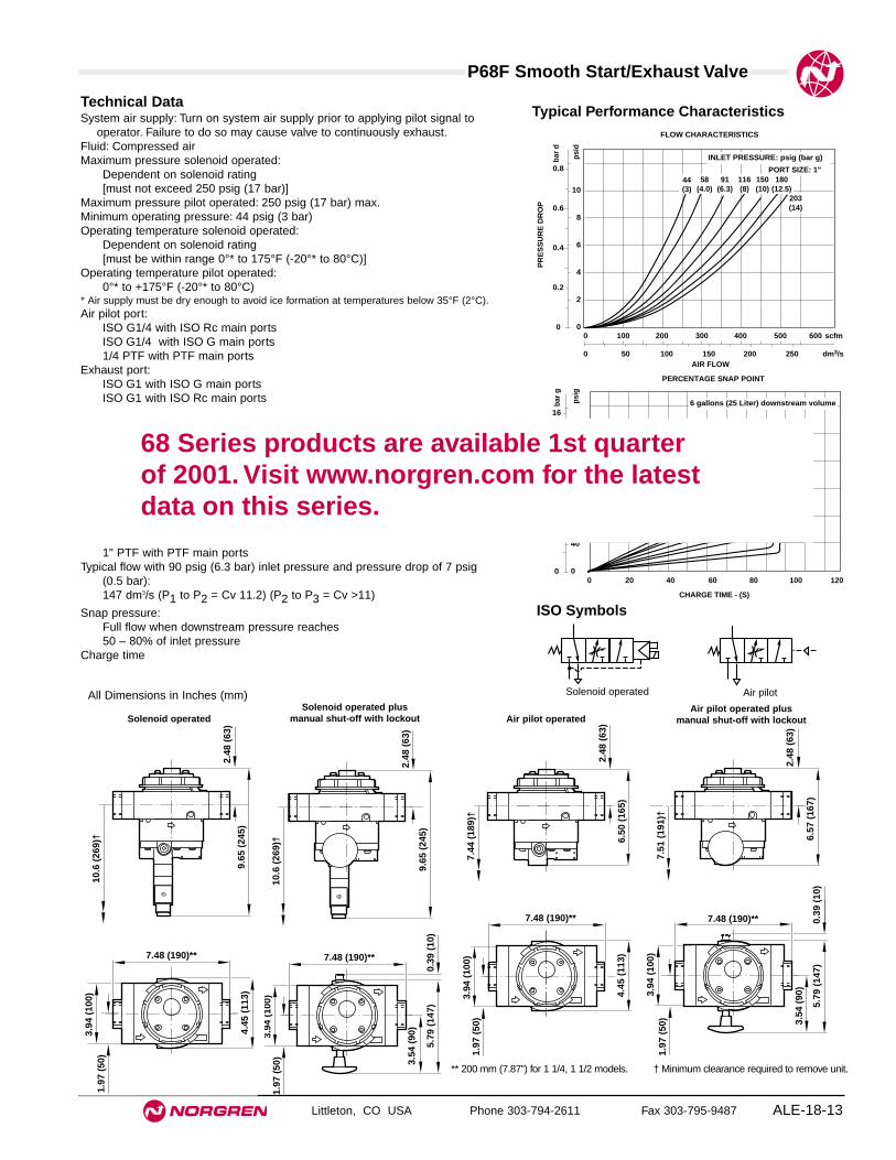
P68F Smooth Start/Exhaust Valve
Littleton, CO USA Phone 303-794-2611 Fax 303-795-9487 ALE-18-13
Technical DataSystem air supply: Turn on system air supply prior to applying pilot signal to
operator. Failure to do so may cause valve to continuously exhaust.Fluid: Compressed airMaximum pressure solenoid operated:
Dependent on solenoid rating [must not exceed 250 psig (17 bar)]
Maximum pressure pilot operated: 250 psig (17 bar) max.Minimum operating pressure: 44 psig (3 bar)Operating temperature solenoid operated:
Dependent on solenoid rating [must be within range 0°* to 175°F (-20°* to 80°C)]
Operating temperature pilot operated:0°* to +175°F (-20°* to 80°C)
* Air supply must be dry enough to avoid ice formation at temperatures below 35°F (2°C).Air pilot port:
ISO G1/4 with ISO Rc main portsISO G1/4 with ISO G main ports1/4 PTF with PTF main ports
Exhaust port:ISO G1 with ISO G main portsISO G1 with ISO Rc main ports
1" PTF with PTF main portsTypical flow with 90 psig (6.3 bar) inlet pressure and pressure drop of 7 psig
(0.5 bar):147 dm3/s (P1 to P2 = Cv 11.2) (P2 to P3 = Cv >11)
Snap pressure:Full flow when downstream pressure reaches 50 – 80% of inlet pressure
Charge time
ISO Symbols
Solenoid operated Air pilot
Typical Performance Characteristics
INLET PRESSURE: psig (bar g)
FLOW CHARACTERISTICS
0 50 100 150 200 250 dm3/sAIR FLOW
0 100 200 300 400 500 600 scfm
PR
ES
SU
RE
DR
OP
0.8
0.6
0.4
0.2
0
bar
d
10
8
6
4
2
0
psi
d
44(3)
91(6.3)
58(4.0)
150(10)
180(12.5)
203(14)
116(8)
PORT SIZE: 1"
7.48 (190)**
4.45
(11
3)
2.48
(63
)9.
65 (
245)
1.97
(50
)3.
94 (
100)
10.6
(26
9)†
2.48
(63
)
9.65
(24
5)
7.48 (190)**
1.97
(50
)3.
94 (
100)
5.79
(14
7)0.
39 (
10)
3.54
(90
)
10.6
(26
9)†
2.48
(63
)
6.50
(16
5)
7.44
(18
9)†
7.48 (190)**
4.45
(11
3)
1.97
(50
)3.
94 (
100)
2.48
(63
)
6.57
(16
7)
7.48 (190)**
1.97
(50
)3.
94 (
100)
5.79
(14
7)0.
39 (
10)
7.51
(19
1)†
3.54
(90
)
Solenoid operated Solenoid operated plus
manual shut-off with lockout Air pilot operatedAir pilot operated plus
manual shut-off with lockout
** 200 mm (7.87") for 1 1/4, 1 1/2 models. † Minimum clearance required to remove unit.
All Dimensions in Inches (mm)
SNAP POINT
PERCENTAGE SNAP POINT
0 20 40 60 80 100 120
CHARGE TIME - (S)
16
12
8
4
0
OU
TL
ET
PR
ES
SU
RE
bar
g
200
160
120
80
40
0 p
sig
6 gallons (25 Liter) downstream volume
68 Series products are available 1st quarter of 2001. Visit www.norgren.com for the latestdata on this series.

See Section ALE-25 for Accessories
Littleton, CO USA Phone 303-794-2611 Fax 303-795-9487
P72C
● Excelon design allows in-line or modular installation
● 3 port/2 position valves, normally closed
● Solenoid or air pilot operated
● Customised poppets for long service life
● High flow spring return
● Modular installations with Excelon 72, 73, and 74series can be made to suit particular applications
Excelon 72 Air or Solenoid Operated Directional Control Valves1/4", 3/8" Port Sizes
ALE-18-14
ISO Symbols
Solenoid operated Air pilot
Ordering Information. Models listed are with PTF threads. Solenoid operated models include 24 V d.c. coil and plug without indicator.
* To select other solenoid type and coil voltage refer to alternative models table below.
Port Size Solenoid Operated* Weight Air Pilot Operated Weight Model lb (kg) Model lb (kg)
1/4" P72C-2AC-PFA 2.11 (0.96) P72C-2AA-NNN 1.86 (0.84)3/8" P72C-3AC-PFA 2.05 (0.93) P72C-3AA-NNN 1.80 (0.82)
P 7 2 -C ★ ★ - ★★ ★ ★
Solenoid Manual Operator SubstituteShrouded push button PNone N
Connectors Substitute3 pin plug with cable gland, Ano indicatorWithout N
** To order air pilot models also substitute ‘NNN’ atdigits 8, 9 and 10 e.g. P72C-2AA-NNN.
Alternative Models
Coil Voltage Nominal SubstitutePower Rating
24 V d.c. 2 W F12 V d.c. 2 W E6 V d.c. 2 W D220/240 V 4/2.5 VA B50/60 Hz110/120 V 4/2.5 VA A50/60 HzNo coil 2 W ZNo solenoid N
Operator SubstituteAir pilot** A22 mm miniature solenoid CCNOMO L
Threads SubstitutePTF AISO Rc taper BISO G parallel G
Port Size Substitute1/4" 23/8" 3

P72C Air or Solenoid Directional Control Valve
Littleton, CO USA Phone 303-794-2611 Fax 303-795-9487 ALE-18-15
All Dimensions in Inches (mm)
Technical DataFluid: Compressed airMaximum pressure solenoid operated: Dependant on solenoid rating [must not
exceed 150 psig (10 bar)]Maximum pressure pilot operated: 150 psig (10 bar)Minimum operating pressure: 15 psig (1 bar)Operating temperature solenoid operated:
Dependant on solenoid rating [must be within range 0°* to 150°F (-20°* to65°C)]
Operating temperature pilot operated:0°* to 150°F (-20°* to 65°C)
* Air supply must be dry enough to avoid ice formation at temperatures below 35°F (2°C).Air Pilot Port:
10-32 UNF with PTF main portsM5 with ISO main ports
Exhaust Port:1/4" PTF with PTF main ports1/4" ISO Rc with ISO Rc main ports1/4" ISO Rc with ISO G main ports
Average flow factor (Cv) IN to OUT ports: 1.31OUT to EXHAUST ports: 1.27
MaterialsBody: Zinc alloyElastomers: Synthetic materialsFilter discs: Sintered plasticInternal components: Brass/steel
2.60 (66)
0.95
(24
)
1.89
(48
)
4.57
(11
6)
6.38
(16
2)
1/4" exhaust port
2.60 (66)
0.95
(24
)
1.89
(48
)
1.77
(45
)
3.58
(91
)
Pilot port
1/4" exhaust port
Solenoid operated
Air pilot operated
Service KitsItem Type Part numberService kit All models 4384-520
Service kit includes all seals, valve assembly and tamper resistant plug.

See Section ALE-25 for Accessories
Littleton, CO USA Phone 303-794-2611 Fax 303-795-9487
P74 Air Operated
● Modular installation only
● High-flow, spring return valves
● 2-port/2-position valves available as normally closedor normally open valves
● 3-port/2-position valves available as normally closedvalves.
● Cushioned poppets for long life
Excelon 74 Air Operated Directional Control ValvesUnthreaded Ports, 1/2" Basic Size
ALE-18-16
ISO Symbols
2-Port/2-PositionNormally Closed
2-Port/2-PositionNormally Open
3-Port/2-PositionNormally Closed
Ordering Information. Models listed include PTF threads in the pilot and exhaust ports.
Installation Type 2 Port/2 Position 2 Port/2 Position 3 Port/2 Position Weight Normally Closed Normally Open Normally Closed lb (kg)
Modular* P74A-NAA-NNN P74B-NAA-NNN P74C-NAA-NNN 1.20 (0.54)* Valve main ports are unthreaded. To install in air line use Quikclamp™ and Quikclamp pipe adapters or connect to other Excelon 74 units.
Alternative Models P 7 4 -★ ★ ★ - ★★ ★ ★
Main Port Threads SubstituteNo threaded ports N
Pilot and Exhaust Port Threads SubstitutePTF AISO Rc BISO G G
Type Substitute2-port/2-position, NC A2-port/2-position, NO B3-port/2-position, NC C
Operator SubstituteAir A
Connector SubstituteNone N
Manual Override SubstituteNone N
Coil SubstituteNone N
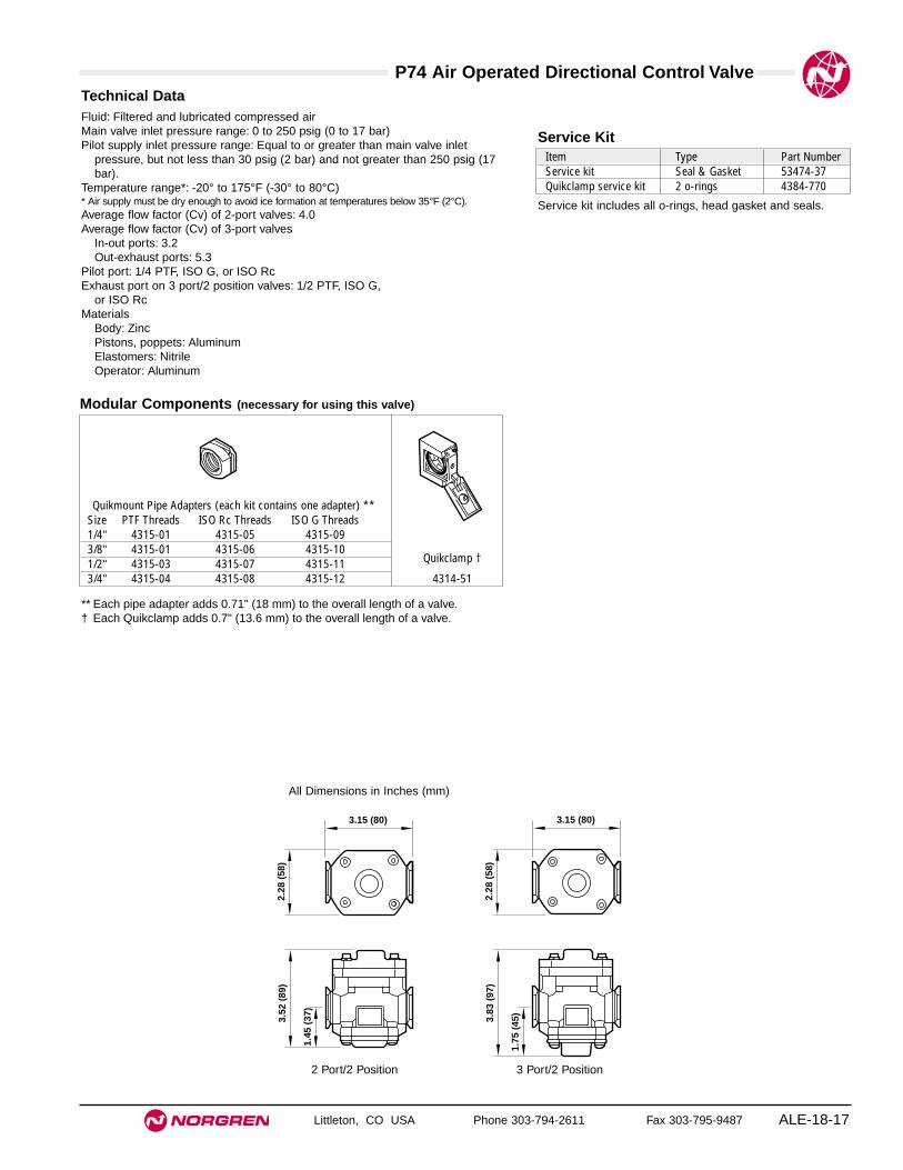
P74 Air Operated Directional Control Valve
Littleton, CO USA Phone 303-794-2611 Fax 303-795-9487 ALE-18-17
All Dimensions in Inches (mm)
Technical DataFluid: Filtered and lubricated compressed airMain valve inlet pressure range: 0 to 250 psig (0 to 17 bar)Pilot supply inlet pressure range: Equal to or greater than main valve inlet
pressure, but not less than 30 psig (2 bar) and not greater than 250 psig (17bar).
Temperature range*: -20° to 175°F (-30° to 80°C) * Air supply must be dry enough to avoid ice formation at temperatures below 35°F (2°C).Average flow factor (Cv) of 2-port valves: 4.0Average flow factor (Cv) of 3-port valves
In-out ports: 3.2Out-exhaust ports: 5.3
Pilot port: 1/4 PTF, ISO G, or ISO RcExhaust port on 3 port/2 position valves: 1/2 PTF, ISO G,
or ISO RcMaterials
Body: ZincPistons, poppets: AluminumElastomers: NitrileOperator: Aluminum
Item Type Part NumberService kit Seal & Gasket 53474-37Quikclamp service kit 2 o-rings 4384-770
Service Kit
Service kit includes all o-rings, head gasket and seals.
2 Port/2 Position 3 Port/2 Position
3.52
(89
)
1.45
(37
)
2.28
(58
)
3.15 (80)
3.83
(97
)
1.75
(45
)
2.28
(58
)
3.15 (80)
Modular Components (necessary for using this valve)
Quikmount Pipe Adapters (each kit contains one adapter) **Size PTF Threads ISO Rc Threads ISO G Threads1/4" 4315-01 4315-05 4315-093/8" 4315-01 4315-06 4315-101/2" 4315-03 4315-07 4315-11 Quikclamp †
3/4" 4315-04 4315-08 4315-12 4314-51
** Each pipe adapter adds 0.71" (18 mm) to the overall length of a valve.† Each Quikclamp adds 0.7" (13.6 mm) to the overall length of a valve.

See Section ALE-25 for Accessories
Littleton, CO USA Phone 303-794-2611 Fax 303-795-9487
P74 Solenoid Operated Valve
● Modular installation only
● High-flow, spring return valves
● 2-port/2-position valves available as normally closedor normally open valves
● 3-port/2-position valves available only as normallyclosed valves.
● Cushioned poppets for long life
Excelon 74 Solenoid Operated Directional Control ValveUnthreaded Ports, 1/2" Basic Size
ALE-18-18
ISO Symbols
2-Port/2-PositionNormally Closed
2-Port/2-PositionNormally Open
3-Port/2-PositionNormally Closed
Ordering Information. Models listed include ISO G exhaust port threads, non-locking override,110/120Vac standard coil, and cable grip connector.
Alternative Models P 7 4 -★ ★ ★ - ★★ ★ ★
Main Port Threads SubstituteNo threaded ports N
Connector SubstituteCable grip ACable grip with indicator lights Band surge protection. Use only with A, F, J and P coils.No connector N
Solenoid SubstituteOperator Standard Low WattCoil Voltage Coil Coil6 Vdc — D12 Vdc Q E24 Vdc P F24 Vac L C110/120 Vac J A220/240 Vac K —No coil Y ZNo solenoid operator N N
Type Substitute2-port/2-position, NC A2-port/2-position, NO B3-port/2-position, NC C
Operator SubstituteSolenoid, internal air pilot C
Installation Type 2 Port/2 Position 2 Port/2 Position 3 Port/2 Position Weight Normally Closed Normally Open Normally Closed lb (kg)
Modular* P74A-NAC-PJA P74B-NAC-PJA P74C-NAC-PJA 1.63 (0.74)* Valve ports are unthreaded. To install in air line use Quikclamp™ and Quikclamp pipe adapters or connect to other Excelon 74 units.
Solenoid Operator Override SubstituteNon-locking, push button PLocking, screwdriver slot SNo solenoid operator N
Exhaust Port Threads SubstitutePTF AISO Rc BISO G GNo exhaust port (2/2 valves) N

P74 Solenoid Operated Directional Control Valve
Littleton, CO USA Phone 303-794-2611 Fax 303-795-9487 ALE-18-19
All Dimensions in Inches (mm)
Technical DataFluid: Filtered and lubricated compressed airMain valve inlet pressure range: 30 to 150 psig (2 to 10 bar)Temperature range*: -20° to 130°F (-30° to 55°C) * Air supply must be dry enough to avoid ice formation at temperatures below 35°F (2°C).Average flow factor (Cv) of 2-port valves: 4.0Average flow factor (Cv) of 3-port valves:
In-out ports: 3.2Out-exhaust ports: 5.3
Response times of 3 port/2 position valve (elapsed time from solenoid energized to an increase in the main valve pressure):
Standard operator: 11 ms at 90 psig (6.3 bar) inlet pressureLow wattage operator: 13.5 ms at 90 psig (6.3 bar) inletpressure
Exhaust port on 3-port/2-position valves: 1/2 PTF, ISO G, or ISO RcSolenoid operator specifications
Voltage and power requirements:Voltage Standard Coil Low Watt Coil6Vdc — 2W12Vdc 7.5W 2W24Vdc 7.5W 3.5W24V 50/60Hz 7.5W 3.5W110/120V 50/60Hz 7.5W 3.5W220/240V 50/60Hz 7.5W —
Duty: Continuous at 90% to 110% of rated voltage.Coil Type: Molded with three pin plug-in connector.Enclosure Classification: NEMA 1, NEMA 4 and IP 65.Connector Plug: Cable grip for cables 1/4" to 5/16" (6 to 8 mm) diameter. Electrical
connectors conform to Industry Standard Form B for Three-Pin Electrical PlugConnectors, 11 mm spacing.
Override: Manual, locking or non-lockingMaterials
Body: ZincPistons, poppets: AluminumElastomers: NitrileOperator housing: PPS plasticOperator base: AluminumPlunger, spring: Stainless steel
2 Port/2 Position 3 Port/2 Position
3.15 (80)
1.97 (50)
1.45
(37
)
6.12
(15
6)2.
28 (
58)
3.15 (80)
1.97 (50)
1.75
(45
)
6.43
(16
3)2.
28 (
58)
Item Type Part NumberService kit Seal & Gasket 53474-37Quikclamp service kit 2 o-rings 4384-770
Service Kit
Service kit includes all o-rings, head gasket and seals.
Modular Components (necessary for using this valve)
Quikmount Pipe Adapters (each kit contains one adapter) **Size PTF Threads ISO Rc Threads ISO G Threads1/4" 4315-01 4315-05 4315-093/8" 4315-01 4315-06 4315-101/2" 4315-03 4315-07 4315-11 Quikclamp †
3/4" 4315-04 4315-08 4315-12 4314-51
** Each pipe adapter adds 0.71" (18 mm) to the overall length of a valve.† Each Quikclamp adds 0.7" (13.6 mm) to the overall length of a valve.

See Section ALE-25 for Accessories
Littleton, CO USA Phone 303-794-2611 Fax 303-795-9487
P74 Lockout Valve
● Modular installation only
● High-flow, 3-port/2-position, normally closed
● Manually operated lockout slide can be locked in theclosed position with a customer supplied padlock.
● Coloured yellow for easy identification as a lockoutvalve
● Cushioned poppets for long life
Excelon 74 Solenoid Operated Valve with LockoutUnthreaded Ports, 1/2" Basic Size
ALE-18-20
ISO Symbol
3-Port/2-PositionNormally Closed
* Valve ports are unthreaded. To install in air line use Quikclamp and Quikclamp pipe adapters or connect to other Excelon 74 units.
Installation Type 3 Port/2 Position Weight Normally Closed lb (kg)
Modular* P74C-NAD-PJA 2.03 (0.92)
Alternative Models P 7 4 -★ ★ ★ - ★★ ★ ★
Main Port Threads SubstituteNo threaded ports N
Type Substitute3-port/2-position, NC C
Operator SubstituteSolenoid, internal air pilot Dwith lockout slide
Solenoid Operator Override SubstituteNon-locking, push button P
Exhaust Port Threads SubstitutePTF AISO Rc BISO G G
Ordering Information. Models listed include PTF exhaust port threads, non-locking override, 110/120Vac coil, and cable grip connector.
Connector SubstituteCable grip ACable grip with indicator lights Band surge protection. Use only with A, F, J and P coils.No connector N
Solenoid SubstituteOperator Standard Low WattCoil Voltage Coil Coil6 Vdc — D12 Vdc Q E24 Vdc P F24 Vac L C110/120 Vac J A220/240 Vac K —No coil Y ZNo solenoid operator N N

P74C Solenoid Operated Valve w/Lockout
Littleton, CO USA Phone 303-794-2611 Fax 303-795-9487 ALE-18-21
All Dimensions in Inches (mm)
Technical DataFluid: Filtered and lubricated compressed airMain valve inlet pressure range: 30 to 150 psig (2 to 10 bar)Temperature range*: -20° to 130°F (-30° to 55°C) * Air supply must be dry enough to avoid ice formation at temperatures below 35°F (2°C).Average flow factor (Cv):
In-out ports: 3.2Out-exhaust ports: 5.3
Response times (elapsed time from solenoid energized to an increase in the main valve pressure): 11 ms at 90 psig (6.3 bar) inlet pressureMaximum diameter of customer supplied padlock shackle: 5/16" (8 mm)Exhaust port: 1/2 PTF, ISO G, or ISO RcSolenoid operator specifications
Voltage and power requirements:Voltage Standard Coil Low Watt Coil6Vdc — 2W12Vdc 7.5W 2W24Vdc 7.5W 3.5W24V 50/60Hz 7.5W 3.5W110/120V 50/60Hz 7.5W 3.5W220/240V 50/60Hz 7.5W —
Duty: Continuous at 90% to 110% of rated voltage.Coil Type: Molded with three pin plug-in connector.Enclosure Classification: NEMA 1, NEMA 4 and IP 65.Connector Plug: Cable grip for cables 6 to 8 mm (1/4" to 5/16") diameter. Electrical
connectors conform to Industry Standard Form B for Three-Pin Electrical PlugConnectors, 11 mm spacing.
Override: Manual, non-lockingMaterials:
Body: ZincPistons, poppets: AluminumElastomers: NitrileOperator housing: PPS plasticOperator base: AluminumPlunger, spring: Stainless steel
2.99 (76)
1.97 (50) Rad.
1.40 (36)
0.57 (15)
3.15 (80)2.28 (58)
1.75
(44
)
6.85
(17
4)
Item Type Part NumberService kit Seal & Gasket 53474-40Quikclamp service kit 2 o-rings 4384-770
Service Kit
Service kit includes all o-rings, lockout slide spring, headgasket and seals.
Modular Components (necessary for using this valve)
Quikmount Pipe Adapters (each kit contains one adapter) **Size PTF Threads ISO Rc Threads ISO G Threads1/4" 4315-01 4315-05 4315-093/8" 4315-01 4315-06 4315-101/2" 4315-03 4315-07 4315-11 Quikclamp †
3/4" 4315-04 4315-08 4315-12 4314-51
** Each pipe adapter adds 0.71" (18 mm) to the overall length of a valve.† Each Quikclamp adds 0.7" (13.6 mm) to the overall length of a valve.

Valves - FAQ’s
Littleton, CO USA Phone 303-794-2611 Fax 303-795-9487ALE-18-22
1.1 SOFT START/DUMP VALVES1.1.1 What Sizes are Available?
We can do units in 1/4" through 11/2" actual port size, based on Excelon 72 (1/4 - 3/8), Olympian Plus 64 (1/4 - 3/4), Excelon 74 (3/8 - 3/4) or the newP68F (3/4 - 11/2").
1.1.2 What Operators are Available?
All valves have air pilot, 22mm solenoid and CNOMO solenoid options. In addition the P68F can use the Webber Excel 32mm solenoid.
1.1.3 Do we have an Emergency Dump?
Yes. The P64F/P74F have an optional dump slide with a yellow handle, used to break the pilot signal and dump the downstream system. The slide can belocked out using a standard 8mm padlock or lockout hasp. The P68F has a dump handle as standard (optional without). Again this can be locked out.
1.1.4 How Fast/Slow can it go?
The snap point where full pressure kicks in is fixed for a given line pressure. You can control the time between signalling the valve and the snap by usingthe needle valve adjuster. Refer to catalogue sheet for minimum/maximum times, which will depend on the downstream system volume.
1.1.5 What is the Minimum Operating Pressure?
The snap action requires a minimum line pressure of 44 psig (3 bar).
1.1.6 Will the Unit Soft Start Only?
The combined function valves are not intended for use as soft start only. If you need such a valve use the Excelon 74 individual valves, or the AOY poppetvalves for Olympian.1.1.7 Will the Unit Dump Only?
The combined function valves are not intended for use as dump only. If you need such a valve use the Excelon 74 individual valves, or the DYO poppetvalves for Olympian.
1.2 EXCELON VALVES
1.2.1 What Versions are Available?
The individual valves for use in Excelon 74 are 2/2 and 3/2 poppet valves P74A and P74B. There is a 2/2 soft start (P74E) and 3/2 on-off valves withsolenoid or pilot operator (P74C). The 3/2 valves have optional lockout slides.
1.2.2 Are the Excelon Valves Direct Ported?
The valves in the Excelon 74 range are intended for modular installation only. If you need a threaded inlet/outlet use a Quikclamp and pipe adapter.

Littleton, CO USA Phone 303-794-2611 Fax 303-795-9487 ALE-19-1
Section 19
ContentsOlympian CS13 Coalescing Exhaust Silencers
1/4", 3/8", 1/2", and 3/4" ports . . . . . . . . . . . . . . . . .ALE-19-2Olympian CS15 Coalescing Exhaust Silencers
3/4", 1", 1-1/4", and 1-1/2" ports . . . . . . . . . . . . . . . .ALE-19-417-016 Drip Leg Drain 1/2" ports . . . . . . . . . . . . . . . . . .ALE-19-6Air Pressure Gauges 1/8" and 1/4" ports . . . . . . . . . . .ALE-19-8High Pressure Needle Valves 1/8" and 1/4" ports . . . .ALE-19-11Regulated Blow Gun 1/4" port . . . . . . . . . . . . . . . . . . .ALE-19-12
Additional CompressedAir ProductsExhaust Silencers, Drip LegDrains, Gauges, Needle Valves,and Blow guns.
CS15 CS13 17-016 Gauges
Needle Valves Blow Gun

See Section ALE-25 for Accessories
Littleton, CO USA Phone 303-794-2611 Fax 303-795-9487
CS13
● Olympian plug in design
● Reduces noise from multi valve and cylinder circuits
● Removes oil mist and sub micron particles fromexhausting air
● Flow in either direction
● Helps to meet noise at work directive
Olympian Plus Coalescing Exhaust Silencers1/4", 3/8", 1/2", 3/4" Port Sizes
ALE-19-2
ISO Symbol
Ordering Information. Models listed include PTF threads.
For single silencer with one main outlet plugged substitute ‘X’ for ‘G’ at the 11th digit eg: CS13-464-10GX.
Port Size Model Weight lb (kg)1/4" CS13-264-10AA 2.98 (1.35)3/8" CS13-364-10AA 2.93 (1.33)1/2" CS13-464-10AA 2.87 (1.30)3/4" CS13-664-10AA 3.66 (1.66)
* For replacement Silencer (without yoke) substitute ‘0’ at the 5th, 8th, 10th and 11th digits eg: CS13-064-0000.
S 1 -3 ★ 6 - ★4 ★ 0 ★
Port Size Substitute1/4" 23/8" 31/2" 43/4" 6
Option SubstituteWith yoke 1Without yoke* 0
Alternative Models
Port Option SubstitutePTF threaded A AISO G threaded D DISO Rc threaded B BOne main outlet plugged (PTF) A XOne main outlet plugged (ISO G) D XOne main outlet plugged (ISO Rc) B X

CS13 Coalescing Exhaust SIlencers
Littleton, CO USA Phone 303-794-2611 Fax 303-795-9487 ALE-19-3
All Dimensions in Inches (mm)
Technical DataFluid: Compressed airMaximum pressure:
0°* to 122°F (-20°* to 50°C)
* Air supply must be dry enough to avoid ice formation at temperatures below 35°F (2°C).Materials
Body: ZincYoke: ZincCage: AluminumElement: Composite materialsElastomers: Synthetic rubberBowl: Polypropylene
Typical Performance Characteristics
FLOW CHARACTERISTICS
0 10 20 30 40 50 dm3/s
AIR FLOW
0 20 40 60 80 100 scfm
PR
ES
SU
RE
DR
OP
0.8
0.6
0.4
0.2
0
bar
d
12
10
8
6
4
2
0
psi
d
CS13-464
** 6.18" (157 mm) for 3/4 models
† Minimum clearance required to remove bowl.
4.13 (105)**
1.87
(47
.5)
3.74
(95
)9.
21 (
234)
9.84
(25
0)†
1.38
(35
)
1/8
Service Kits
Item Part NumberService kit CS13RKReplacement element 3236-01
Service kit includes bowl, drain plug and drain retainer.

See Section ALE-25 for Accessories
Littleton, CO USA Phone 303-794-2611 Fax 303-795-9487
CS15
● Olympian plug in design
● Effectively reduce noise emission of multi valve andcylinder systems
● Remove oil mist and sub-micron particles fromexhaust air
● Single or double units for high flow rates
● Flow in either direction
● Helps to meet noise at work directive
Olympian Coalescing Exhaust Silencers3/4", 1", 1-1/4", 1-1/2" Port Sizes
ALE-19-4
ISO Symbol
Automatic Drain
Ordering Information. Models listed include PTF threads.
For replacement silencer without yoke substitute ‘0’ at the 5th, 8th, 10th and 11th digits eg:CS15-000-0000.
Port Size Single Weight lb (kg) Double Weight lb (kg)3/4" CS15-600-10AA 5.20 (2.34) CS15-600-20AA 9.47 (4.26)1" CS15-800-10AA 5.09 (2.29) CS15-800-20AA 9.36 (4.21)1-1/4" – CS15-A00-20AA 9.49 (4.27)1-1/2" – CS15-B00-20AA 9.51 (4.28)
Alternative ModelsSC 1 -5 ★ 0 - 00 ★ ★★
Port Size Substitute3/4" 61" 81-1/4" A1-1/2" B
Option SubstituteSingle yoke 1Double yoke 2
Port Option SubstitutePTF threaded A AISO G threaded D DISO Rc threaded B BOne main outlet plugged (PTF) A XOne main outlet plugged (ISO G) D XOne main outlet plugged (ISO Rc) B X

CS15 Coalescing Exhaust SIlencers
Littleton, CO USA Phone 303-794-2611 Fax 303-795-9487 ALE-19-5
All Dimensions in Inches (mm)
Technical DataFluid: Compressed airOperating temperature*
Metal bowl: 0° to 122°F (-20° to 50°C)* Air supply must be dry enough to avoid ice formation at temperatures below 35°F (2°C).Materials
Body: AluminumYoke: AluminumCage: AluminumBowl: PolypropyleneElement: Composite materialsElastomers: Synthetic rubber
Typical Performance Characteristics
PRESSURE DR0P vs AIR FLOW
CS15-800
0 10 20 30 40 dm3/s
AIR FLOW
0 20 40 60 80 100 scfm
PR
ES
SU
RE
DR
OP
1000
900
800
700
600
500
400
300
200
100
0
mba
r d
14
12
10
8
6
4
2
0
psi
d
† Minimum clearance required to remove bowl.
13.9
(35
4)†
1.77
(45
)
7.48 (190)
1.97
(50
)
3.94
(10
0)
∅4.
33 (
110)
13.0
(33
0)
1/8
13.9
(35
4)†
1.77
(45
)
12.4 (315)
1.97
(50
)
3.94
(10
0)
∅4.
33 (
110)
13.0
(33
0)
1/8
Single unit
Double unit
SILENCER COMPARED WITH OPEN LINE
CS15-800
Open line
10 100 1 000 10 000
FREQUENCY - Hz
120
100
80
60
SO
UN
D P
RE
SS
UR
E L
EV
EL
- d
B
Service KitsItem Part NumberService kit CS15RKReplacement elements 5576-97
Service kit includes: bowl, drain plug and drain retainer.

Littleton, CO USA Phone 303-794-2611 Fax 303-795-9487
17-016
● Automatically expels liquids from the piping network
● Can be disassembled without the use of tools orremoval from the air line
● Automatic drain valve opens when system isunpressurized, allowing water to escape by gravity
● Automatic drain valve is float operated when systemis pressurized
● Install at low points and at far end of piping network
Drip Leg Drain1/2" Port Size
ALE-19-6
ISO Symbol
Automatic Drain
Port Size Bowl Type Bowl Size Model Number Weight lbs (kg)1/2" PTF Transparent 1/3 pint (0.16 liter) 17-016-104 0.8 (0.38)1/2" PTF Metal with sight glass 1/3 pint (0.16 liter) 17-016-107 1.3 (0.59)1/2" PTF Transparent 3 fluid ounce (0.09 liter) 17-016-102 0.8 (0.38)
Ordering Information.

Drip Leg Drain
Littleton, CO USA Phone 303-794-2611 Fax 303-795-9487 ALE-19-7
All Dimensions in Inches (mm)
Technical DataFluid: Compressed airMaximum pressure
Transparent bowl: 150 psig (10 bar)Metal bowl: 250 psig (17 bar)
Operating temperature* Transparent bowl: 0° to 125°F (-20° to 50°C)Metal bowl: 0° to 175°F (-20° to 80°C)
* Air supply must be dry enough to avoid ice formation at temperatures below 35°F (2°C).Automatic drain connection: 1/8" pipe threadAutomatic drain operating conditions (float operated):
Bowl pressure required to close drain: Greater than 5 psig (0.3 bar)Minimum air flow thru drain required to close drain: 2 scfm (1 dm3/s).Bowl pressure required to open drain: Less than 3 psig (0.2 bar)Manual operation: Depress pin inside drain outlet to drain bowlFlexible tube with 0.125" (3mm) minimum I.D. can be connected to the drain.Avoid restrictions in the tube.
Nominal bowl size Standard: 1/3 pint (0.16 liter)Optional: 3 fluid ounce (0.09 liter)
MaterialsBody: ZincBowl
Transparent: PolycarbonateMetal: Zinc
Drain mechanism: Acetal, Nitrile, stainless steelMetal bowl liquid level indicator lens: PyrexElastomers: Nitrile
1.34 (34)Radius
2.31 (59)Dia.
1/2-14 PTF
6.22
(15
8)
.
4.75
(12
1)
1/3 Pint (0.16 Liter) Bowl
3 Fluid Ounce (0.09 Liter) Bowl
7.25
(18
4) *
*
5.78
(14
7) *
*
Service KitsItem Type Part NumberReplacement drain Automatic 3000-10Liquid level lens kit Pyrex 2273-20
** Minimum clearance required to remove bowl.

Littleton, CO USA Phone 303-794-2611 Fax 303-795-9487
18-013, 5PG
● Monitor pressures in compressed air systems foroptimum efficiency
● Triple calibrated scale indicates pressure in psi, bar,and Mpa (megapascal)
● Back or bottom connection
● Panel mount, stainless steel, and UnderwritersLaboratories, Inc. listed gauges available
Air Pressure Gauges1/8" and 1/4" Port Sizes
ALE-19-8
ISO Symbol
Technical DataFluid: Compressed air and inert gassesMaximum pressure: 100% of full scale on gaugeOperating temperature: -30° to 175°F (-34° to 80°C)** Air supply must be dry enough to avoid ice formation at temperatures below 35°F (2°C).Accuracy:
2% of full scale at midrange3% of full scale at other ranges
MaterialsBody
Standard: Gauges may have a steel or plastic bodyOptional: Stainless steel
Crystal:Standard steel and plastic bodies have plastic crystalOptional stainless steel body has glass crystal
Connector:Standard steel and plastic bodies have brass connector Optional stainless steel body has stainless steel connector

Air Pressure Gauges
Littleton, CO USA Phone 303-794-2611 Fax 303-795-9487 ALE-19-9
All Dimensions in Inches (mm)
Center Back Connection, Panel Mounted
Ordering Information, Black Face Gauges - psi outer scale, bar middle scale, Mpa inner scale
Bottom Connection - 2" (50 mm) diameter gauges do not have the Mpa scale
Scale Range 1/4 NPT MaleOuter Middle Inner and 10-32 FemaleScale Scale Scale 1.5" (40mm)psig bar Mpa Diameter0 to 30 0 to 2 0 to 0.2 5PG-306-000 **0 to 60 0 to 4 0 to 0.4 5PG-312-000 **0 to 100 0 to 7 0 to 0.7 5PG-320-000 **
Alternative ModelsPulsation Dampener: Add -9D to the end of the model number.
* Underwriters Laboratories Inc. Listed† Shipped with pulsation dampener installed.
Center Back Connection
Scale RangeOuter Middle Inner 1/8 NPT 1/8 NPT 1/4 NPT R1/4Scale Scale Scale 1.5" (40mm) 2" (50mm) 2" (50mm) 2" (50mm)psig bar Mpa Diameter Diameter Diameter Diameter0 to 30 0 to 2 0 to 0.2 18-013-214 18-013-201 18-013-207 —0 to 60 0 to 4 0 to 0.4 18-013-211 18-013-202 18-013-208 18-013-2680 to 100 0 to 7 0 to 0.7 — 18-013-203 18-013-235 —0 to 160 0 to 11 0 to 1.1 18-013-212 18-013-204 18-013-209 18-013-2690 to 300 0 to 20 0 to 2.1 — 18-013-205 18-013-210 18-013-2700 to 400 0 to 28 0 to 2.8 — 18-013-206 — —
Scale RangeOuter Middle Inner 1/8 NPT 1/4 NPTScale Scale Scale 1.5" (40mm) 2" (50mm)psig bar Mpa Diameter Diameter0 to 15 0 to 1 — — 18-013-0820 to 30 0 to 2 0 to 0.2 18-013-224 18-013-030 *0 to 60 0 to 4 0 to 0.4 18-013-225 18-013-083 *0 to 100 0 to 7 0 to 0.7 18-013-265 18-013-084 *0 to 160 0 to 11 0 to 1.1 18-013-273 18-013-085 *0 to 300 0 to 20 — — 18-013-086 *0 to 2000 0 to 135 — — 18-013-244 *†0 to 3000 0 to 205 — — 18-013-087 *†
A B C1.5 (40) 1.60 (41) 0.47 (12)2.0 (50) 1.85 (47) 0.55 (14)
C (
SQ
)
BøA
A B C D1.5 (40) 1.42 (36) 0.90 (23) 0.47 (12)2.0 (50) 1.73 (44) 1.03 (26) 0.55 (14)
B
C
D (SQ)
ø A
A B C D E F (Max) G1.5 (40) 1.51 (38) 0.86 (22) 1.61 (41) 0.18 (5) 0.5 (13) 0.55 (14)
G(S
Q)
ø D
E
BC
ø A
F (Max)
** Requires 1.63" (41 mm) diameter panel hole.

Air Pressure Gauges
Littleton, CO USA Phone 303-794-2611 Fax 303-795-9487ALE-19-10
All Dimensions in Inches (mm)
Ordering Information, White Face Gauges - bar outer scale, Mpa middle scale, psi inner scale
Center Back Connection
Scale RangeOuter Middle Inner R1/8 R1/8 R1/8Scale Scale Scale 1.5" (40mm) 2" (50mm) 2.5" (63mm)bar Mpa psi Diameter Diameter Diameter0 to 1.6 0 to 0.16 0 to 23 18-013-991 18-013-010 —0 to 4 0 to 0.4 0 to 56 18-013-990 18-013-011 —0 to 6 0 to 0.6 0 to 84 — 18-013-012 —0 to 10 0 to 1.0 0 to 140 18-013-989 18-013-013 18-013-8560 to 16 0 to 1.6 0 to 240 — — 18-013-8550 to 25 0 to 2.5 0 to 360 18-013-908 18-013-014 —
Bottom Connection
Scale RangeOuter Middle Inner R1/8 G1/4AScale Scale Scale 2" (50mm) 2.5" (63mm)bar Mpa psi Diameter Diameter0 to 1.6 0 to 0.16 0 to 23 18-013-024 —0 to 4 0 to 0.4 0 to 56 18-013-025 —0 to 6 0 to 0.6 0 to 84 18-013-026 —0 to 10 0 to 1.0 0 to 140 18-013-027 18-013-8540 to 16 0 to 1.6 0 to 240 — 18-013-8530 to 25 0 to 2.5 0 to 360 18-013-028 —
Center Back Connection, Panel Mount
Scale RangeOuter Middle Inner G1/8A G1/8AScale Scale Scale 2" (50mm) 2.5" (63mm)bar Mpa psi Diameter Diameter0 to 6 0 to 0.6 0 to 84 18-013-858 * —0 to 10 0 to 1.0 0 to 140 18-013-857 * 18-013-852 †0 to 16 0 to 1.6 0 to 240 — 18-013-851 †
Stainless Steel Gauges - gauges do not have the Mpa scale
Scale RangeOuter Inner 1/8 PTF 1/4 PTFScale Scale 1.5" (40mm) 1.5" (40mm)bar psi Diameter Diameter0 to 6 0 to 84 — 18-013-9130 to 10 0 to 140 18-013-844 18-013-9090 to 25 0 to 360 — 18-013-905
* Requires 2.01" (51 mm) diameter panel hole.† Requires 2.52" (64 mm) diameter panel hole.
A B C D E F2.0 (50) 2.17 (55) 1.02 (26) 1.93 (49) 0.20 (5) 0.37 (9.5)2.5 (63) 2.20 (56) 1.06 (27) 2.44 (62) 0.24 (6) 0.37 (9.5)
ø D
CB
F (Max)
ø AE
A B C D2.0 (50) 1.77 (45) 1.10 (28) 0.55 (14)2.5 (63) 2.09 (53) 1.10 (28) 0.55 (14)
B
ø A C
D (SQ)
A B C1.5 (40) 1.77 (45)* 0.55 (14)2.0 (50) 1.93 (49) 0.55 (14)2.5 (63) 1.89 (48) 0.55 (14)
ø A B
C (
SQ
)
* 1.57 (40) on 1/8 PTF stainless steel gauges1.85 (47) on 1/4 PTF stainless steel gauges

Littleton, CO USA Phone 303-794-2611 Fax 303-795-9487
● Bar stock machined brass body● Tapered brass needle● Adjustable stem packing nut with Teflon® seal● Retained adjustment stem● Metal to metal sealing surfaces● Accurate metering of fluids● 3,000 psig inlet pressure
High Pressure Needle Valves1/8" and 1/4" Port Sizes
ALE-19-11
SpecificationsFluid: Compressed air, water, steam, and othernon-flammable, inert gases and liquidsMax. Inlet Pressure: 3,000 psig (207 bar)Temperature Range: -40° to 500°F (-40° to 260°C)Maximum Differential Pressure: 15 psid (1 bar d)Ports: 1/8 or 1/4 NPTOrifice Size: Ø0.187" (5 mm)CV: 0.401
Materials of ConstructionBody, needle, packing nut, knob: BrassStem Seal: Teflon®
DimensionsSize Port Part C
(NPT) In Out Number A B Closed OpenMale Male 17-001-106 1.63 (41) 0.38 (10) 2.13 (54) 2.25 (57)
1/8" Female Female 17-001-109 1.63 (41) 0.38 (10) 2.13 (54) 2.25 (57)Female Male 17-001-112 1.63 (41) 0.38 (10) 2.13 (54) 2.25 (57)
Male Male 17-001-107 1.81 (46) 0.38 (10) 2.13 (54) 2.25 (57)1/4" Female Female 17-001-110 1.63 (41) 0.38 (10) 2.13 (54) 2.25 (57)
Male Female 17-001-114 1.72 (44) 0.38 (10) 2.13 (54) 2.25 (57)
B
A
C
B
A
C
B
C
A
17-001-10617-001-107
17-001-10917-001-110
17-001-11217-001-114
240
Fluid: WaterOutlet Pressure: AtmoshpereAdjustment Knob: Full Open
psig
bar
16
12
8
4
0
160
80
0
INL
ET
PR
ES
SU
RE
WATER FLOW
0
0 4
1.0 2.0
8
3.0
12
4.0 5.0
16
gpm
20l/min.
150
Fluid: AirOutlet Pressure: AtmoshpereAdjustment Knob: Full Open
psig
bar
10
7.5
5.0
2.5
0
100
50
0IN
LE
T P
RE
SS
UR
E
AIR FLOW
0
0 5
10 20
10
30
15
40 50
20
scfm
25dm3/s

Littleton, CO USA Phone 303-794-2611 Fax 303-795-9487
Regulated Blow Gun1/4" Port Size
● Nozzle pressure regulated to below 30 psig (2.1 bar) even if nozzle is obstructed
● OSHA compliant
● Large lever for comfort and easy actuation
● Permanently assembled, tamper resistantconstruction
● Surface scratching reduced by ordering modelwith rubber tipped nozzle
● Replaceable nozzle tip
● 10" extension nozzle available
ALE-19-12
SpecificationsFluid: Compressed airMaximum Inlet Pressure: 250 psig (17.2 bar)Temperature Range: 32° to 175°F (0° to 79°C)Outlet (Regulated) Pressure: Below 30 psig (2.1 bar)Nozzle Orifice: Ø0.16" (Ø4 mm)Port Size: 1/4 PTF (female)
Materials of ConstructionBody: PolyesterNozzle Tip: Metal (aluminum or brass) or RubberElastomers: Nitrile
AccessoriesHanging Hook: 5320-0110" Extension Nozzle: 5363-50
Replacement PartsNozzle with Air Shield: 1135-05Nozzle without Air Shield: 1135-06Nozzle Rubber Tip: 1135-07
Port Part Nozzle(PTF) Number Type
1/4 17-104-302 Metal Tip with Air Shield1/4 17-104-304 Metal Tip1/4 17-104-306 Rubber Tip

Littleton, CO USA Phone 303-794-2611 Fax 303-795-9487 ALE-20-1
Section 20
Filter-FilterModular prefilter and oil removalfilter combination units in portsize from 1/4" to 3/4"
F72 Filter-FilterCombination Unit
F73 Filter-FilterCombination Unit F74 Filter-Filter
Combination Unit
Excelon 72 Filter Combination Units 1/4" and 3/8" Port Sizes . . . . . . . . . . . . . . . . . . . . . ALE-20-2
Excelon 73 Filter Combination Units 1/4", 3/8", 1/2" Port Sizes . . . . . . . . . . . . . . . . . . . . . . . . . ALE-20-4
Excelon 74 Filter Combination Units 3/8", 1/2", 3/4" Port Sizes . . . . . . . . . . . . . . . . . . . . . . . . . ALE-20-6

See Section ALE-25 for Accessories
Littleton, CO USA Phone 303-794-2611 Fax 303-795-9487
F72G, F72C
● True modularity with Norgren Quikclamp™connections
● F72G prefilter and F72C oil removal filter providehigh efficiency oil removal and particle removal downto 0.01 µm
● Quick release bayonet bowl
● Highly visible, prismatic liquid level indicator lens
● Service indicator turns from green to red when thefilter element needs to be replaced
Excelon 72 Filter Combination Units 1/4" and 3/8" Port Sizes
ALE-20-2
Ordering information. Models listed include PTF threads, service indicator, automatic drain, and long transparent bowl without guard on both filters.
Alternative Models
Threads SubstitutePTF AISO Rc taper BISO G parallel G
Mechanical Service Indicator SubstituteIndictor on F72G and F72C BIndictor only on F72C CIndictor only on F72G DNo indicator N
Quikclamp Wall Brackets SubstituteWith BWithout N
F72G Filter Element Substitute5 µm 1
Combination Unit Type SubstituteF72G general purpose filter and AF72C coalescing filter
Port Size Substitute1/4" 23/8" 3
★ - ★★ N7 2 -A★ ★ ★ - ★★ ★ - NN N
Shutoff/Lockout Valve, Quikmount SubstituteStandard Combination (No HShutoff/Lockout Valve, no Quikmount)With Shutoff/Lockout valve on inlet JWith Quikmount pipe adapters Mon inlet and outletWith Shutoff/Lockout Valve on inlet Nand Quikmount pipe adapter on outlet
Adsorbing Filter Bowl SubstituteNo Adsorbing filter N
Regulator Option SubstituteNon Applicable N
Regulator Option SubstituteNon Applicable N
Regulator Option SubstituteNon Applicable N
Port Size Model Weight lb (kg)1/4" H72A-2AB-AL1-NNN-LNN 2 (0.91)3/8" H72A-3AB-AL1-NNN-LNN 2 (0.91)
F72G and F72C Drain SubstituteAutomatic** AManual, 1⁄4 turn QSemi automatic S
** Supplied in long bowl options only.
F72C Bowl SubstituteShort metal with liquid level indicator DLong metal with liquid level indicator EShort transparent without guard TLong transparent without guard LLong transparent with guard W
F72G Bowl SubstituteShort metal with liquid level indicator DLong metal with liquid level indicator EShort transparent without guard TLong transparent without guard LLong transparent with guard W

F72G, F72C Filter-Filter
Littleton, CO USA Phone 303-794-2611 Fax 303-795-9487 ALE-20-3
All Dimensions in Inches (mm)Technical DataFluid: Compressed airMaximum pressure:
Transparent bowl: Manual or semi automatic drain: 150 psig (10 bar)Automatic drain: 116 psig (8 bar)
Metal bowl: Manual or semi automatic drain: 250 psig (17 bar)Automatic drain: 116 psig (8 bar)
Operating temperature*: Transparent bowl: -30° to 125°F (-34° to 50°C)Metal bowl: -30° to 150°F (-34 to 65°C)
* Air supply must be dry enough to avoid ice formation at temperatures below 35°F (2°C).Particle removal: Down to 0.01 µmAir quality: Within ISO 8573-1, Class 1 (particulates) and Class 2 (oil content)Maximum remaining oil content in outlet air: 0.01 ppm at 70°F (20°C) with an inlet
concentration of 17 ppmManual drain connection: Will fit 1/8-27 and 1/8-28 pipe threadSemi automatic drain connection: Push on 5/16" (8 mm) ID tubeSemi automatic drain operating conditions (pressure operated)
Bowl pressure required to close drain: Greater than 1.5 psig (0.1 bar)Bowl pressure required to open drain: Less than 1.5 psig (0.1 bar) Minimum air flow required to close drain: 1 scfm (0.5 dm3/s)Manual operation: Lift stem to drain bowl
Automatic drain connection: Will fit 1/8-27 and 1/8-28 pipe threadFlexible tube with 3/16" (5 mm) minimum I.D. can be connected to the automatic
drain. Drain may fail to operate if the tube I.D. is less than 3/16" (5 mm). Avoidrestrictions in the tube.
Automatic drain operating conditions (float operated) Bowl pressure required to close drain: Greater than 5 psig (0.3 bar) Bowl pressure required to open drain: Less than 3 psig (0.2 bar)Minimum air flow required to close drain: 0.2 scfm (0.1 dm3/s)Manual operation: Depress pin inside drain outlet to drain bowl
Nominal bowl sizeShort bowl: 1.9 fluid ounce (56 ml)
Long bowl: 2.2 fluid ounce (65 ml)Materials
Body: ZincBowl
Transparent: PolycarbonateTransparent with guard: Polycarbonate, zinc guardMetal: ZincMetal bowl liquid level indicator lens: Transparent nylon
F72G element: Sintered polypropyleneF72C element: Synthetic fiber and polyurethane foamElastomers: Neoprene and nitrileService indicator materials
Body: Transparent nylonInternal parts: AcetalSpring: Stainless steelElastomers: Nitrile
Standard Type H72A-Shown with optional Quikclampwall bracket.
2.32
(59
) 1.
50(3
8)
4.22 (108)
2.11(54)
2.11(54)
Alternative Type J72A-Includes Shutoff/Lockout valve.Shown with optional Quikclampwall brackets.
Alternative Type M72A-Includes Quikmount pipe adapters.Shown with optional Quikclamp wallbrackets.
2.32
(59
)
4.48 (113)
6.00 (152)
1.50
(38)
Alternative Type N72A-Includes Shutoff/Lockout valveand Quikmount pipe adapter.Shown with optional Quikclampwall brackets.
2.32
(59
)
6.46 (164)
2.24(56)
2.11(54)
2.11(54)
1.50
(38)
7.35 (187)
2.32
(59
)
4.48 (113)2.11(54)
1.50
(38)
ISO Symbols
Automatic andSemi Automatic Drain
Manual Drain

Littleton, CO USA Phone 303-794-2611 Fax 303-795-9487
F73G, F73C
● True modularity with Norgren Quikclamp connections
● F73G prefilter and F73C oil removal filter providehigh efficiency oil removal and particle removal downto 0.01 µm
● Quick release bayonet bowl
● Highly visible, prismatic liquid level indicator lens
● Service indicator turns from green to red when thefilter element needs to be replaced
Excelon 73 Filter Combination Units1/4", 3/8", 1/2" Port Sizes
ALE-20-4
Ordering information. Models listed include PTF parallel threads, service indicator, automatic drain, and metal bowl with liquid level indicator
on both filters.
Alternative Models
Threads SubstitutePTF AISO Rc taper BISO G parallel G
Mechanical Service Indicator SubstituteIndictor on F73G and F73C BIndictor only on F73C CIndictor only on F73G DNo indicator N
Quikclamp Wall Brackets SubstituteWith BWithout N
F73G Filter Element Substitute5 µm 1
Combination Unit Type SubstituteF73G general purpose filter and AF73C coalescing filter
Port Size Substitute1/4" 23/8" 31/2" 4
★ - ★★ N7 3 -A★ ★ ★ - ★★ ★ - NN N
Lockout Valve/Quikmount SubstituteStandard Combination (No HLockout Valve, no Quikmount)With Lockout valve on inlet JWith Quikmount pipe adapters Mon inlet and outletWith Lockout Valve on inlet and NQuikmount pipe adapter onoutlet
Adsorbing Filter Bowl SubstituteNo Adsorbing filter N
F73C Bowl SubstituteMetal with liquid level indicator DTransparent with guard PTransparent T
Regulator Option SubstituteNon Applicable N
Regulator Option SubstituteNon Applicable N
Regulator Option SubstituteNon Applicable N
F73G Bowl SubstituteMetal with liquid level indicator DTransparent with guard PTransparent T
Port Size Model Weight lb (kg)1/4" H73A-2AB-AD1-NNN-DNN 2.7 (1.22)3/8" H73A-3AB-AD1-NNN-DNN 2.7 (1.22)1/2" H73A-4AB-AD1-NNN-DNN 2.7 (1.22)
F73G and F73C Drain SubstituteAutomatic AManual, 1⁄4 turn Q

See Section ALE-25 for Accessories
F73G, F73C Filter-Filter
Littleton, CO USA Phone 303-794-2611 Fax 303-795-9487 ALE-20-5
All Dimensions in Inches (mm)Technical DataFluid: Compressed airMaximum pressure:
Transparent bowl: 150 psig (10 bar)Metal bowl: 250 psig (17 bar)
Operating temperature*:Transparent bowl: -30° to 125°F (-34° to 50°C)Metal bowl: -30° to 150°F (-34° to 65°C)
* Air supply must be dry enough to avoid ice formation at temperatures below 35°F (2°C).Particle removal: Down to 0.01 µmAir quality: Within ISO 8573-1, Class 1 (particulates) and Class 2 (oil content)Maximum remaining oil content in outlet air: 0.01 ppm at 70°F (20°C) with an inlet
concentration of 17 ppmManual drain connection: Will fit 1/8-27 and 1/8-28 pipe threadAutomatic drain connection: Will fit 1/8-27 and 1/8-28 pipe threadFlexible tube with 3/16" (5 mm) minimum I.D. can be connected to the automatic
drain. Drain may fail to operate if the tube I.D. is less than 3/16" (5 mm). Avoidrestrictions in the tube.
Automatic drain operating conditions (float operated):Bowl pressure required to close drain: Greater than 5 psig (0.3 bar)Bowl pressure required to open drain: Less than 3 psig (0.2 bar)Minimum air flow required to close drain: 0.2 scfm (0.1 dm3/s) Manual operation: Depress pin inside drain outlet to drain bowl
Nominal bowl size: 3.5 fluid ounce (0.1 liter)Materials
Body: AluminumBowl
Transparent: PolycarbonateTransparent with guard: Polycarbonate, steel guardMetal: AluminumMetal bowl liquid level indicator lens: Transparent nylon
F73G element: Sintered polypropyleneF73C element: Synthetic fiber and polyurethane foamElastomers: Neoprene and nitrileService indicator materials
Body: Transparent nylonInternal parts: AcetalSpring: Stainless steelElastomers: Nitrile
ISO Symbols
Automatic Drain Manual Drain
Standard Type H73A-Shown with optionalQuikclamp wall bracket.
5.91 (150)
2.95(75)
2.95(75)
3.25
(83)
2.00
(51
)
Alternative Type J73A-Includes Lockout ValveShown with optionalQuikclamp wall brackets.
2.40(61)
2.95(75)
3.23(82)
8.58 (218)
3.25
(83)
2.00
(51
)
Alternative Type M73A-Includes Quikmount PipeAdaptersShown with optionalQuikclamp wall brackets.
8.39 (213)
6.42 (163)
3.25
(83)
2.00
(51
)
Alternative Type N73A-Includes Lockout Valve andQuikmount Pipe AdaptersShown with optionalQuikclamp wall brackets.
9.80 (249)
2.40(61) 6.42 (163)
3.25
(83)
2.00
(51
)

Littleton, CO USA Phone 303-794-2611 Fax 303-795-9487
F74G, F74C/H, F74V
● True modularity with Norgren Quikclamp™connections
● F74G prefilter and F74C oil removal filter providehigh efficiency oil removal and particle removal downto 0.01 µm
● F74V oil vapor removal filter uses an adsorbing typeactivated carbon element to remove oil vapors andmost hydrocarbon odors
● Quick release bayonet bowl
● Highly visible, prismatic liquid level indicator lens
● Service indicator turns from green to red when thefilter element needs to be replaced
Excelon 74 Filter Combination Units3/8", 1/2", 3/4" Port Sizes
Technical DataFluid: Compressed airMaximum pressure
Transparent bowl: 150 psig (10 bar)Metal bowl: 250 psig (17 bar)
F74G and F74C/H operating temperature*:Transparent bowl: -30° to 125°F (-34° to 50°C)Metal bowl: -30° to 150°F (-34° to 65°C)
F74V temperature range*: -30° to 150°F (-34° to 65°C).* Air supply must be dry enough to avoid ice formation at temperatures below 35°F (2°C).Particle removal: Down to 0.01 µmAir quality:
F74G, F74C/H: Within ISO 8573-1, Class 1 (particulates) and Class 2 (oilcontent)F74G, F74C, F74V: Within ISO 8573-1, Class 1 (particulates) and Class 1 (oilcontent)
Maximum remaining oil content in outlet air with an inlet concentration of 17 ppmF74G, F74C/H: 0.01 ppm at 70°F (20°C)F74G, F74H, F74V: 0.003 ppm at 70°F (20°C)
Manual drain connection: Will fit 1/8-27 and 1/8-28 pipe threadAutomatic drain connection: Will fit 1/8-27 and 1/8-28 pipe threadAutomatic drain operating conditions (float operated)
Bowl pressure required to close drain: Greater than 5 psig (0.3 bar)Bowl pressure required to open drain: Less than 3 psig (0.2 bar)Minimum air flow required to close drain: 2 scfm (1 dm3/s) Manual operation: Depress pin inside drain outlet to drain bowl
Nominal bowl size: 7 fluid ounce (0.2 liter)Materials
Body: AluminumBowl
Transparent: Polycarbonate with steel bowl guardMetal: Aluminum
Metal bowl liquid level indicator lens: Transparent nylonF74G element: Sintered polypropyleneF74C/H element: Synthetic fiber and polyurethane foamF74V element: Activated carbon and aluminumElastomers: Neoprene and nitrileService indicator materials:
Body: Transparent nylonInternal parts: AcetalSpring: Stainless steelElastomers: Nitrile
ALE-20-6
See Section ALE-25 for Accessories
ISO Symbols
Automatic Drain Manual Drain Closed Bottom

F74G, F74C/H, F74V Filter-Filter
Littleton, CO USA Phone 303-794-2611 Fax 303-795-9487 ALE-20-7
Ordering information. Models listed include PTF parallel threads, service indicator on the general purpose and coalescing filters, automaticdrain and metal bowl with liquid level indicator on the general purpose and coalescing filters.
Alternative Models
Threads SubstitutePTF AISO Rc taper BISO G parallel G
Service Indicator SubstituteOn general purpose and Bcoalescing filtersOnly on coalescing filter COnly on general purpose filter DNo service Indicator N
General Purpose Filter and SubstituteCoalescing Filter DrainAutomatic AManual, 1⁄4 turn Q
Quikclamp Wall Brackets SubstituteWith BWithout N
General Purpose Filter Element Substitute5 µm 1
Combination Unit Type SubstituteGeneral purpose filter and Astandard coalescing filterGeneral purpose filter and Bhigh flow coalescing filterGeneral purpose filter, Fstandard coalescing filter, andadsorbing filter
Port Size Substitute3/8" 31/2" 43/4" 6
★ - ★★ ★7 4 -★★ ★ ★ - ★★ ★ - NN N
Lockout Valve/ Quikmount SubstituteStandard combination (no Hlockout valve or Quikmount)With lockout valve on inlet JWith Quikmount pipe adapters Mon inlet and outletWith lockout valve on inlet and NQuikmount pipe adapter onoutlet
Adsorbing Filter Bowl SubstituteMetal, closed bottom MNo adsorbing filter N
Coalescing Filter Bowl SubstituteMetal with liquid level indicator DTransparent with metal guard P
Regulator Option SubstituteNon applicable N
Regulator Option SubstituteNon applicable N
Regulator Option SubstituteNon applicable N
General Purpose Filter Bowl SubstituteMetal with liquid level indicator DTransparent with guard P
Combination Unit Type Port Size Model Weight lb (kg)
General Purpose andStandard 3/8" H74A-3AB-AD1-NNN-DNN 4.15 (1.88)
Coalescing FiltersStandard 1/2" H74A-4AB-AD1-NNN-DNN 4.06 (1.84)High Flow 1/2" H74B-4AB-AD1-NNN-DNN 4.67 (2.12)High Flow 3/4" H74B-6AB-AD1-NNN-DNN 4.61 (2.09)
General Purpose,Coalescing, Standard 3/8" H74F-3AB-AD1-NNN-DMN 7.12 (3.23) and Adsorbing Filters Standard 1/2" H74F-4AB-AD1-NNN-DMN 7.01 (3.18)

All Dimensions in Inches (mm)
F74G, F74C/H, F74V Filter-Filter
Littleton, CO USA Phone 303-794-2611 Fax 303-795-9487ALE-20-8
Standard Type H74A Shown(H74B Similar)Shown with optional Quikclamp wallbracket.
6.84 (174)
3.42(87)
3.42(87)
3.25
(83)
2.00
(51
)
Standard Type H74FShown with optional Quikclamp wallbracket.
Standard Type J74A Shown(J74B Similar)Includes Shutoff/Lockout valve Shown with optional Quikclamp wallbrackets. 3.03
(77)3.42(87)
3.68(94)
10.13 (257)
3.25
(83)
2.00
(51
)
Alternative Type J74F-Includes Shutoff/Lockout valveShown with optional Quikclampwall brackets.
10.52 (267)
3.42(87)
3.42(87)
3.68(94)
3.25
(83)
2.00
(51
)
13.81 (351)
3.03(77)
3.42(87)7.37 (187)
3.25
(83)
2.00
(51
)
Standard Type M74A Shown (M74B Similar)Includes Quikmount pipe adapters.Shown with optional Quikclamp wallbracket.
9.32 (237)
7.37 (187)
3.25
(83)
2.00
(51
)
Alternative Type M74F-Includes Quikmount pipeadapters.Shown with optional Quikclampwall brackets.
Standard Type N74A Shown (N74B Similar)Includes Shutoff/Lockout valve andQuikmount pipe adapter.Shown with optional Quikclamp wallbrackets.
11.37 (289)
3.03(77) 7.37 (187)
3.25
(83)
2.00
(51
)
Alternative Type N74F-Includes Shutoff/Lockout valveand Quikmount pipe adapter.Shown with optional Quikclampwall brackets.
13.00 (330)
11.05 (281)2.00
(51
)3.
25(8
3)
2.00
(51
)
15.05 (382)
3.03(77) 11.05 (281)
3.25
(83)

Littleton, CO USA Phone 303-794-2611 Fax 303-795-9487 ALE-21-1
Section 21
07 Series Filter/Regulator-Lubricator Combination Units 1/8" and 1/4" port sizes . . . . . . . . . . . . . . . . . . . . .ALE-21-2
Excelon 72 Filter/Regulator-Lubricator Combination Units 1/4" and 3/8" port sizes . . . . . . . . . . . . . . . . . . . . .ALE-21-4
Excelon 73 Filter/Regulator-Lubricator Combination Units 1/4", 3/8", and 1/2" port sizes . . . . . . . . . . . . . . . . .ALE-21-8
Excelon 74 Filter/Regulator-Lubricator Combination Units 3/8", 1/2", and 3/4" port sizes . . . . . . . . . . . . . . . .ALE-21-12
Olympian 64 Filter/Regulator-Lubricator Combination Units 1/4", 3/8", 1/2", and 3/4" port sizes . . . . . . . . . . .ALE-21-16
Filter/Regulator-Lubricator Combination units in port sizesfrom 1/8" to 3/4".
07 Series F/R-L 72 Series F/R-L
73 Series F/R-L 74 Series F/R-L 64 Series F/R-L

See Section ALE-25 for Accessories
Littleton, CO USA Phone 303-794-2611 Fax 303-795-9487
P1H, PTH Combination Unit
● Compact design
● Filter removes liquids and solid particles down to5 µm
● Push to lock adjusting knob with tamper resistantoption
● Micro-Fog lubricator provides air line lubrication toone or more air driven tools or other devices
● Nearly constant oil density output with varying airflow
● Can be disassembled without the use of tools orremoval from the air line
07 Series Filter/Regulator-Lubricator1/8" and 1/4" Port Sizes
ALE-21-2
Ordering Information. Models listed include PTF threads, transparent bowls, filter/regulator with relieving diaphragm, automatic drain, 5 µmelement, 5 to 100 psig (0.3 to 7 bar) outlet pressure adjustment range*, gauge, and lubricator with manual drain.
Port Size Model Number Weight lbs (kg)1/8" P1H-100-A1AA 0.87 (40)1/4" P1H-200-A1AA 0.87 (40)
Alternative Models - ★★★ ★★ ★ -★ ★P H
Threads SubstitutePTF AISO Rc taper BISO G parallel G
Filter/Regulator Drain SubstituteAutomatic AManual M
Port Size Substitute1/8" 11/4" 2
Integral Wall Bracket SubstituteWithout (P1H Combination Unit) 1With (PTH Combination Unit) T
Filter/Regulator Element Substitute5 µm 140 µm 3
Lubricator Reservoir SubstituteTransparent with drain ATransparent without drain QMetal with drain MMetal without drain F
* Outlet pressure can be adjusted to pressures in excess of, and less than, those specified. Do not use these units to control pressures outsideof the specified ranges.
Outlet PressureFilter/Regulator Adjustment Range* ReliefBowl bar psig Type Gauge SubstituteTransparent 5 to 100 0.3 to 7 Relieving With 00Transparent 5 to 100 0.3 to 7 Relieving Without 01Transparent 5 to 100 0.3 to 7 Non-relieving Without 02Transparent 5 to 100 0.3 to 7 Non-relieving With 03Transparent 5 to 50 0.3 to 3.5 Relieving Without 04Transparent 5 to 50 0.3 to 3.5 Relieving With 05Transparent 5 to 50 0.3 to 3.5 Non-relieving Without 06Transparent 5 to 50 0.3 to 3.5 Non-relieving With 07Metal / no sight glass 5 to 100 0.3 to 7 Relieving With 40Metal / no sight glass 5 to 100 0.3 to 7 Relieving Without 41Metal / no sight glass 5 to 100 0.3 to 7 Non-relieving Without 42Metal / no sight glass 5 to 100 0.3 to 7 Non-relieving With 43Metal / no sight glass 5 to 50 0.3 to 3.5 Relieving Without 44Metal / no sight glass 5 to 50 0.3 to 3.5 Relieving With 45Metal / no sight glass 5 to 50 0.3 to 3.5 Non-relieving Without 46Metal / no sight glass 5 to 50 0.3 to 3.5 Non-relieving With 47

07 Series Filter/Regulator-Lubricator
Littleton, CO USA Phone 303-794-2611 Fax 303-795-9487 ALE-21-3
ISO Symbols
Relieving filter/regulator with automaticdrain, lubricator with manual drain
Non relieving filter/regulator with automaticdrain, lubricator with manual drain
Technical DataFluid: Compressed airMaximum pressure
Transparent bowl: 150 psig (10 bar)Metal bowl: 250 psig (17 bar)
Operating temperature*Transparent bowl: 0° to 125°F (-20° to 50°C)Metal bowl: 0° to 150°F (-20° to 65°C)
* Air supply must be dry enough to avoid ice formation at temperatures below 35°F (2°C)Typical flow at 100 psig (7 bar) inlet pressure, 90 psig (6.3 bar) set pressure and a
droop of 15 psig (1 bar) from set:1/8" ports: T.B.A.1/4" ports: 6 scfm (3 dm3/s)
Drain connection: 1/8" pipeFilter/RegulatorParticle removal: 5 µm or 40 µm. Within ISO 8573-1, Class 3 and Class 5Gauge ports:
1/8" PTF with PTF main ports1/8" ISO Rc with ISO Rc main ports1/8" ISO Rc with ISO G main ports
Automatic drain operation: Spitter type drain operates momentarily when a rapidchange in air flow occurs or when the supply pressure is reduced.
LubricatorStart point (i.e., minimum flow required for lubricator operation): 0.5 scfm
(0.24 dm3/s) at 90 psig (6.3 bar) inlet pressureNominal bowl capacity: 1 fluid ounce (31 ml)Recommended lubricants: See Section ALE-29.Materials
Bodies: ZincFilter/Regulator bonnet: AcetalFilter/Regulator valve: Brass/nitrileFilter/Regulator valve seat: AcetalBowls
Transparent: PolycarbonateMetal: Zinc
Lubricator sight-feed dome: Transparent nylonFilter element: Sintered polypropyleneElastomers: Nitrile
1.68
(43
)
1.26
(32
)
2.13
(54
)
1.50 (38)
1.78 (45) 1.78 (45)
3.55 (90)
1.50
(38
)
0.174††(4)
Dia.
0.29(7)
Dia.
0.55
(14)
1.12
(28
)
2.67
(68
)3.
72 (
94)
Au
tom
atic
Dra
in
0.38
(10
)
3.87
(98
) M
anu
al D
rain
1.65
(42
)3.
07 (
78)
Wit
ho
ut
Dra
in
8.31
(21
1)†
0.55
(14)
†Minimum distance required to remove bowl†† Mounting holes
Service KitsItem Type Part numberService kits, relieving, 5 µm element 3820-02filter/regulator non relieving, 5 µm element 3820-01Service kit, lubricator 3795-03
Replacement drains Manual 773-03Automatic 3654-02
Replacement wall Integral 2 piece 6700-30bracket for PTH unitFilter/regulator service kit contains slip ring, diaphragm, valve seatwith o-ring, valve, valve spring, element, element gasket, and bowlo-ring.
Lubricator service kit contains sight-feed dome seal, cartridge o-ring, and bowl o-ring.
All Dimensions in Inches (mm)

See Section ALE-25 for Accessories
Littleton, CO USA Phone 303-794-2611 Fax 303-795-9487
B72, L72 Combination Units
● True modularity with Norgren Quikclamp™connections
● Quick release bayonet bowl
● Lubricator flow sensor provides a nearly constantoil/air ratio over a wide range of air flows
● All around (360°) visibility of the lubricator sight-feeddome simplifies installation and adjustment
● Regulator balanced valve minimizes effect of variationin the inlet pressure on the outlet pressure
Use Micro-Fog models in applications containing one or more points of lubrication.
Use Oil-Fog models to lubricate a single tool, cylinder, or other air driven device.
Excelon 72 Series Filter/Regulator-Lubricator 1/4" and 3/8" Port Sizes
Technical DataFluid: Compressed airMaximum pressure:
Transparent bowl: 150 psig (10 bar)Metal bowl (manual or semi automatic drain): 250 psig (17 bar)Automatic drain: 150 psig (10 bar)
Operating temperature*:Transparent bowl: 0° to 125°F (-20° to 50°C)Metal bowl: 0° to 150°F (-20° to 65°C)
* Air supply must be dry enough to avoid ice formation at temperatures below 35°F (2°C ).
Particle removal: 5 µm, 25 µm, or 40 µm filter elementManual drain connection: Will fit 1/8-27 and 1/8-28 pipe threadSemi automatic drain connection: Push on 5/16" (8 mm) ID tubeSemi automatic drain operating conditions (pressure operated)
Bowl pressure required to close drain: Greater than 1.5 psig (0.1 bar)Bowl pressure required to open drain: Less than 1.5 psig (0.1 bar) Minimum air flow required to close drain: 1 scfm (0.5 dm3/s)Manual operation: Lift stem to drain bowl
Automatic drain connection: Will fit 1/8-27 and 1/8-28 pipe threadAutomatic drain operating conditions (float operated):
Bowl pressure required to close drain: Greater than 5 psig (0.3 bar) Bowl pressure required to open drain: Less than 3 psig (0.2 bar)Minimum air flow required to close drain: 0.2 scfm (0.1 dm3/s)Manual operation: Depress pin inside drain outlet to drain bowl
Nominal bowl sizeShort bowl: 1.9 fluid ounce (56 ml)Long bowl: 2.2 fluid ounce (65 ml)
Gauge ports: 1/8 PTF with PTF main portsRc 1/8 with ISO Rc and ISO G main ports
Recommended lubricants: See Section ALE-29.Materials
Body: ZincBonnet: AcetalFilter/Regulator valve: BrassBowl: Transparent: Polycarbonate
Transparent with guard: Polycarbonate, zinc guardMetal: ZincMetal bowl liquid level indicator lens: Transparent nylon
Sight-Feed dome: Transparent nylonElement: Sintered polypropyleneElastomers: Neoprene, nitrile
ALE-21-4
ISO Symbol
Filter with automatic drain, Regulator with relieving diaphragm,Lubricator with manual drain

Excelon 72 Filter/Regulator-Lubricator
Littleton, CO USA Phone 303-794-2611 Fax 303-795-9487 ALE-21-5
Combination Unit Type SubstituteStandard Micro-Fog F/R-L HStandard Oil-Fog F/R-L JMicro-Fog F/R-L with porting Kblock between filter/regulatorand lubricatorOil-Fog F/R-L with porting Lblock between filter/regulatorand lubricator
Alternative Models
Threads SubstitutePTF AISO Rc taper BISO G parallel G
Filter Drain SubstituteAutomatic † AManual, 1⁄4 turn QSemi automatic S
Pressure Adjustment SubstituteKnob KT-bar T
Filter Element Substitute5 µm 125 µm 240 µm 3
Port Size Substitute1/4" 23/8" 3
★ - ★★ ★7 2 -★★ ★ ★ - ★★ ★ - ★★ ★
Regulator Gauge SubstituteWith gauge GNo gauge N
Regulation spring ** Substitute5 to 30 psig (0.3 to 2 bar) C5 to 60 psig (0.3 to 4 bar) F5 to 150 psig (0.3 to 10 bar) M
Regulator Diaphragm SubstituteNon-relieving NRelieving R
Lubricator Drain SubstituteClosed bottom EManual, 1⁄4 turn Q
Accessories SubstituteQuikclamp wall brackets BNo accessories N
** Outlet pressure can be adjusted to pressures in excess of, and less than, those specified. Do not use these units to control pressures outside of thespecified ranges.
† Supplied in long bowl options only.
Ordering information. Models include PTF threads. Filter/Regulator (F/R) has knob adjustment, automatic drain, long transparent bowl with
guard, 40 µm element, relieving diaphragm, and 150 psig (10 bar) regulating spring, and gauge. Lubricator (L) is a Micro-Fog model with 1/4 turn
manual drain and long transparent bowl with guard.
Combination Unit Type Port Size Model Weight lb (kg)Filter/Regulator-Lubricator 1/4" C72H-2AK-AW3-RMG-QWN 2.37 (1.08)(F/R-L) 3/8" C72H-3AK-AW3-RMG-QWN 2.37 (1.08)
Shutoff/Lockout Valve, Quikmount SubstituteStandard Combination (No CShutoff/Lockout Valve, no Quikmount)With Shutoff/Lockout valve on inlet DWith Quikmount pipe adapters Eon inlet and outletWith Shutoff/Lockout Valve on inlet Gand Quikmount pipe adapter on outlet
Filter Bowl SubstituteShort metal with liquid level indicator DLong metal with liquid level indicator EShort transparent without guard TLong transparent without guard LLong transparent with guard W
Lubricator Bowl SubstituteShort metal with liquid level indicator DLong metal with liquid level indicator EShort transparent without guard TLong transparent without guard LLong transparent with guard W

72 Series Filter/Regulator-Lubricator
Littleton, CO USA Phone 303-794-2611 Fax 303-795-9487ALE-21-6
All Dimensions in Inches (mm)
Standard Micro-Fog Type C72H-Standard Oil-Fog Type C72J-
Shown with optional Quikclamp wall bracket.
2.32
(59
) 1.
50 (
38)
4.22 (108)
2.11(54)
2.11(54)
Alternative Micro-Fog Type D72H- Alternative Oil-Fog Type D72J-
Includes Shutoff/Lockout valve.
Shown with optional Quikclamp wall brackets.
Alternative Micro-Fog Type E72H- Alternative Oil-Fog Type E72J-
Includes Quikmount pipe adapters.
Shown with optional Quikclamp wall brackets.
4.48 (113)
6.00 (152)
2.32
(59
) 1.
50 (
38)
Alternative Micro-Fog Type G72H- Alternative Oil-Fog Type G72J-
Includes Shutoff/Lockout valve and Quikmount pipeadapter.
Shown with optional Quikclamp wall brackets.
2.24 (56)
6.46 (164)
2.32
(59
)
1.50
(38
)
2.11 (54) 2.11 (54)
4.48 (113)
7.35 (187)
2.32
(59
) 1.
50 (
38)
2.11(54)

Excelon 72 Filter/Regulator-Lubricator
Littleton, CO USA Phone 303-794-2611 Fax 303-795-9487 ALE-21-7
All Dimensions in Inches (mm)
5.87 (149)
8.74 (222)
2.32
(59
) 1.
50 (
38)
2.11(54)
Alternative Micro-Fog Type C72K- Alternative Oil-Fog Type C72L-
Includes porting block.
Shown with optional Quikclamp wall brackets.
Alternative Micro-Fog Type D72K- Alternative Oil-Fog Type D72L-
Includes Shutoff/Lockout valve and porting block.Shown with optional Quikclamp wall brackets.
Alternative Micro-Fog Type E72K- Alternative Oil-Fog Type E72L-
Includes Quikmount pipe adapters and porting block.
Shown with optional Quikclamp wall brackets.
5.87 (149)
7.39 (188)
2.32
(59
) 1.
50 (
38)
2.32
(59
)
1.39(35)
5.61 (143)
1.50
(38)
2.11(54)
2.11(54)
3.63 (92)
7.85 (200)
2.32
(59
) 1.
50(3
8)
2.11(54)
2.11(54)
Alternative Micro-Fog Type G72K- Alternative Oil-Fog Type G72L-
Includes Shutoff/Lockout valve, Quikmount pipeadapter, and porting block.Shown with optional Quikclamp wall brackets.

See Section ALE-25 for Accessories
Littleton, CO USA Phone 303-794-2611 Fax 303-795-9487
B73, L73 Combination Units
● True modularity with Norgren Quikclamp™connections
● Quick release bayonet bowl
● Lubricator flow sensor provides a nearly constantoil/air ratio over a wide range of air flows
● All around (360°) visibility of the lubricator sight-feeddome simplifies installation and adjustment
● Regulator balanced valve minimizes effect of variationin the inlet pressure on the outlet pressure
Use Micro-Fog models in applications containing one or more points of lubrication.
Use Oil-Fog models to lubricate a single tool, cylinder, or other air driven device.
Excelon 73 Series Filter/Regulator-Lubricator 1/4", 3/8", and 1/2" Port Sizes
Technical DataFluid: Compressed airMaximum pressure:
Transparent bowl: 150 psig (10 bar)Metal bowl: 250 psig (17 bar)
Operating temperature*:Transparent bowl: 0° to 125°F (-20° to 50°C)Metal bowl: 0° to 175°F (-20° to 80°C)
* Air supply must be dry enough to avoid ice formation at temperatures below 35°F (2°C).Particle removal: 5 µm, 25 µm, or 40 µm filter elementManual drain connection: Will fit 1/8-27 and 1/8-28 pipe threadAutomatic drain connection: Will fit 1/8-27 and 1/8-28 pipe threadAutomatic drain operating conditions (float operated)
Bowl pressure required to close drain: Greater than 5 psig (0.3 bar)Bowl pressure required to open drain: Less than 3 psig (0.2 bar)Minimum air flow required to close drain: 0.2 scfm (0.1 dm3/s) Manual operation: Depress pin inside drain outlet to drain bowl
Nominal bowl size: 3.5 fluid ounce (0.1 liter)Gauge ports:
1⁄4 PTF with PTF main portsISO Rc1/4 with ISO Rc main portsISO Rc1/8 with ISO G main ports
Recommended lubricants: See Section ALE-29.Materials
Body: AluminumBonnet: AluminumFilter/Regulator valve: BrassBowl
Transparent: PolycarbonateTransparent with guard: Polycarbonate, steel guardMetal: Aluminum or ZincMetal bowl liquid level indicator lens: Transparent nylon
Sight-Feed dome: Transparent nylonElement: Sintered plasticElastomers: Neoprene and nitrile
ALE-21-8

Excelon 73 Filter/Regulator-Lubricator
Littleton, CO USA Phone 303-794-2611 Fax 303-795-9487 ALE-21-9
ISO Symbol
Relieving, automatic drain on filter, manual drain on lubricator
Ordering informationModels listed in order table have PTF parallel threads. Filter/Regulator (F/R) has knob adjustment, automatic drain, metal bowl with liquid levelindicator, 40 µm element, relieving diaphragm, and 150 psig (10 bar) regulating spring, with gauge.Lubricator (L) is a Micro-Fog model with 1/4 turn manual drain and metal bowl with liquid level indicator.
Alternative Models
Threads SubstitutePTF AISO Rc taper BISO G parallel G
Accessories SubstituteQuikclamp wall brackets BAccessories B and Q CNo accessories NLubricator quick fill nipple Q
Pressure Adjustment SubstituteKnob KT-bar T
Filter Element Substitute5 µm 125 µm 240 µm 3
Combination Unit Type SubstituteStandard Micro-Fog F/R-L HStandard Oil-Fog F/R-L JMicro-Fog F/R-L with porting Kblock between filter/regulatorand lubricatorOil-Fog F/R-L with porting Lblock between filter/regulatorand lubricator
Port Size Substitute1/4" 23/8" 31/2" 4
★ - ★★ ★7 3 -★★ ★ ★ - ★★ ★ - ★★ ★
Lockout Valve/ Quikmount SubstituteStandard Combination (No CLockout Valve, no Quikmount)With Lockout valve on inlet DWith Quikmount pipe adapters Eon inlet and outletWith Lockout valve on inlet and GQuikmount pipe adapter onoutlet
Lubricator Bowl SubstituteMetal with liquid level indicator DTransparent with guard PTransparent T
Filter/Regulator Gauge SubstituteWith gauge GNo gauge N
Filter Drain SubstituteAutomatic AManual, 1⁄4 turn Q
Combination Unit Type Port Size Model Weight lb (kg)
Filter/Regulator-Lubricator1/4" C73H-2AK-AD3-RMG-QDN 3.0 (1.36)
(F/R-L)3/8" C73H-3AK-AD3-RMG-QDN 3.0 (1.36)1/2" C73H-4AK-AD3-RMG-QDN 3.0 (1.36)
Lubricator Drain SubstituteClosed bottom EManual, 1⁄4 turn Q
Regulation Spring * Substitute5 to 60 psig (0.3 to 4 bar) F5 to 150 psig (0.3 to 10 bar) M10 to 250 psig (0.7 to 17 bar)** S
Filter/Regulator Diaphragm SubstituteNon-relieving NRelieving R
Filter Bowl SubstituteMetal with liquid level indicator DTransparent with steel guard PTransparent T
* Outlet pressure can be adjusted to pressures in excess of, andless than, those specified. Do not use these units to controlpressures outside of the specified ranges.
** Units with 250 psig (17 bar) outlet pressure range are availableonly with the standard metal bowl.
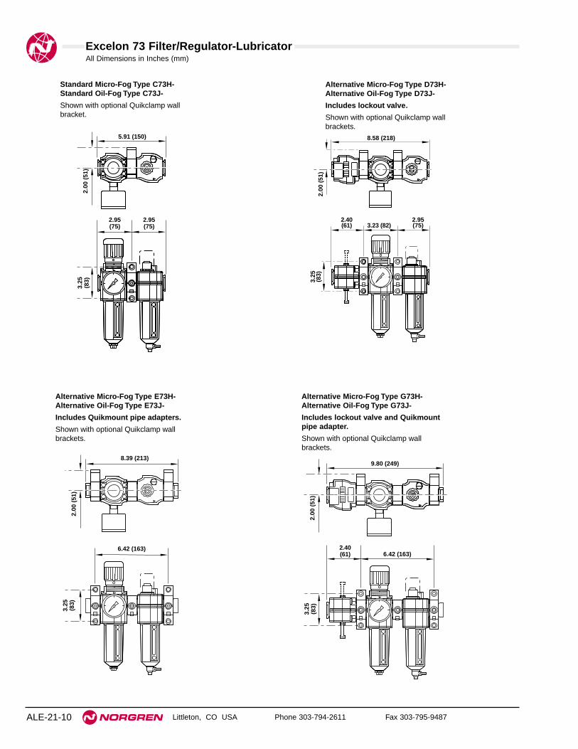
Excelon 73 Filter/Regulator-Lubricator
Littleton, CO USA Phone 303-794-2611 Fax 303-795-9487ALE-21-10
All Dimensions in Inches (mm)
Standard Micro-Fog Type C73H-Standard Oil-Fog Type C73J-
Shown with optional Quikclamp wallbracket.
2.95(75)
2.95(75)
5.91 (150)
3.25
(83)
2.00
(51
)Alternative Micro-Fog Type D73H- Alternative Oil-Fog Type D73J-
Includes lockout valve.
Shown with optional Quikclamp wallbrackets.
3.23 (82)2.40(61)
2.95(75)
8.58 (218)
3.25
(83)
2.00
(51
)
Alternative Micro-Fog Type E73H- Alternative Oil-Fog Type E73J-
Includes Quikmount pipe adapters.
Shown with optional Quikclamp wallbrackets.
6.42 (163)
8.39 (213)
3.25
(83)
2.00
(51
)
Alternative Micro-Fog Type G73H- Alternative Oil-Fog Type G73J-
Includes lockout valve and Quikmountpipe adapter.
Shown with optional Quikclamp wallbrackets.
6.42 (163)2.40(61)
9.80 (249)
3.25
(83)
2.00
(51
)

Excelon 73 Filter/Regulator-Lubricator
Littleton, CO USA Phone 303-794-2611 Fax 303-795-9487 ALE-21-11
All Dimensions in Inches (mm)
8.27 (210)2.40(61)
11.63 (295)
3.25
(83)
2.00
(51
)
2.40(61)
2.95(75)5.04 (128)
10.39 (264)
3.25
(83)
2.00
(51
)
2.95(75)
2.95(75)
7.76 (197)
3.25
(83)
2.00
(51
)
1.85(47)
Alternative Micro-Fog Type C73K- Alternative Oil-Fog Type C73L-
Includes porting block.
Shown with optional Quikclamp wall brackets.
Alternative Micro-Fog Type D73K- Alternative Oil-Fog Type D73L-
Includes lockout valve and porting block.
Shown with optional Quikclamp wall brackets.
Alternative Micro-Fog Type E73K- Alternative Oil-Fog Type E73L-
Includes Quikmount pipe adapters andporting block.
Shown with optional Quikclamp wallbrackets.
8.27 (210)
10.20 (259)
3.25
(83)
2.00
(51
)
Alternative Micro-Fog Type G73K- Alternative Oil-Fog Type G73L-
Includes lockout valve, Quikmountpipe adapter, and porting block.
Shown with optional Quikclamp wall brackets.

See Section ALE-25 for Accessories
Littleton, CO USA Phone 303-794-2611 Fax 303-795-9487
B74, L74 Combination Units
● True modularity with Norgren Quikclamp™connections
● Quick release bayonet bowl
● Lubricator flow sensor provides a nearly constantoil/air ratio over a wide range of air flows
● All around (360°) visibility of the lubricator sight-feeddome simplifies installation and adjustment
● Regulator balanced valve minimizes effect of variationin the inlet pressure on the outlet pressure
Use Micro-Fog models in applications containing one or more points of lubrication.
Use Oil-Fog models to lubricate a single tool, cylinder, or other air driven device.
74 Series Filter/Regulator-Lubricator 3/8", 1/2", and 3/4" Port Sizes
Technical DataFluid: Compressed airMaximum pressure:
Transparent bowl: 150 psig (10 bar)Metal bowl: 250 psig (17 bar)
Operating temperature*:Transparent bowl: 0° to 125°F (-20° to 50°C)Metal bowl: 0° to 175°F (-20° to 80°C)
* Air supply must be dry enough to avoid ice formation at temperatures below 35°F (2°C).Particle removal: 5 µm, 25 µm, or 40 µm filter elementManual drain connection: 1/8"Automatic drain connection: 1/8"Automatic drain operating conditions (float operated)
Bowl pressure required to close drain: Greater than 5 psig (0.3 bar)Bowl pressure required to open drain: Less than 3 psig (0.2 bar)Minimum air flow required to close drain: 2 scfm (1 dm3/s) Manual operation: Depress pin inside drain outlet to drain bowl
Nominal bowl size:Standard: 7 fluid ounce (0.2 liter)Optional size for lubricator: 1 quart US (1 liter)
Gauge Ports:1/4" PTF with PTF main portsRc 1/4 with ISO Rc main portsRc 1/8 with ISO G main ports
Recommended lubricants: See Section ALE-29.Materials:
Body: AluminumBonnet: AluminumFilter/Regulator valve: BrassBowl
Transparent: Polycarbonate with steel bowl guardMetal: Aluminum
Metal bowl liquid level indicator lens:7 fluid ounce (0.2 liter): Transparent nylon1 quart US (1 liter): Pyrex
Sight-Feed dome: Transparent nylonElement: Sintered polypropyleneElastomers: Neoprene and nitrile
ALE-21-12

Excelon 74 Filter/Regulator-Lubricator
Littleton, CO USA Phone 303-794-2611 Fax 303-795-9487 ALE-21-13
ISO Symbol
Filter with automatic drain, Regulator with relievingdiaphragm, Lubricator with manual drain
Ordering information. Models listed include Micro-Fog lubricator, PTF threads, knob pressure adjustment, metal filter bowl with liquid level indicator andautomatic drain, 40 µm filter element, relieving diaphragm, 150 psig (10 bar) regulating spring, with gauge, 7 fluid oz. (0.2 liter) metal lubricator bowl with liquid levelindicator and 1/4 turn manual drain.
Alternative Models
Threads SubstitutePTF AISO Rc taper BISO G parallel G
Filter Drain SubstituteAutomatic AManual, 1⁄4 turn Q
Accessories SubstituteQuikclamp wall brackets BQuikclamp wall brackets Cand lubricator quick fill nippleNo accessories NLubricator quick fill nipple Q
Pressure Adjustment SubstituteKnob KT-bar T
Filter Element Substitute5 µm 125 µm 240 µm 3
Combination Unit Type SubstituteStandard Micro-Fog F/R-L HStandard Oil-Fog F/R-L JMicro-Fog F/R-L with porting Kblock between filter/regulatorand lubricatorOil-Fog F/R-L with porting Lblock between filter/regulatorand lubricator
Port Size Substitute3/8" 31/2" 43/4" 6
★ - ★★ ★7 4 -★★ ★ ★ - ★★ ★ - ★★ ★
Lockout Valve/ Quikmount SubstituteStandard combination (no Clockout valve or Quikmount)With lockout valve on inlet DWith Quikmount pipe adapters Eon inlet and outletWith lockout valve on inlet and GQuikmount pipe adapter onoutlet
Lubricator Bowl Substitute1 quart US (1 liter) metal with Aliquid level indicator7 fluid oz. (0.2 liter) metal Dwith liquid level indicator7 fluid oz. (0.2 liter) transparent Pwith zinc guard
Filter/Regulator Gauge SubstituteWith gauge GNo gauge N
Filter Bowl SubstituteMetal with liquid level indicator DTransparent with guard P
Combination Unit Type Port Size Model Weight lb (kg)
Filter/Regulator-Lubricator3/8" C74H-3AK-AD3-RMG-QDN 5.20 (2.36)
(F/R-L)1/2" C74H-4AK-AD3-RMG-QDN 5.07 (2.30)3/4" C74H-6AK-AD3-RMG-QDN 5.00 (2.27)
Lubricator Drain SubstituteClosed bottom EManual, 1⁄4 turn QRemote fill †† R
Regulation spring ** Substitute5 to 60 psig (0.3 to 4 bar) F5 to 150 psig (0.3 to 10 bar) M10 to 250 psig (0.7 to 17 bar)† S
Filter/Regulator Diaphragm SubstituteNon relieving NRelieving R
** Outlet pressure can be adjusted to pressures in excess of, and lessthan, those specified. Do not use these units to control pressuresoutside of the specified ranges.
† Units with 250 psig (17 bar) outlet pressure range are available onlywith the T-bar adjustment; therefore substitute T at the 7th positionand S at the 12th position.
†† Use remote fill only with 7 fluid oz. (0.2 liter) bowls.
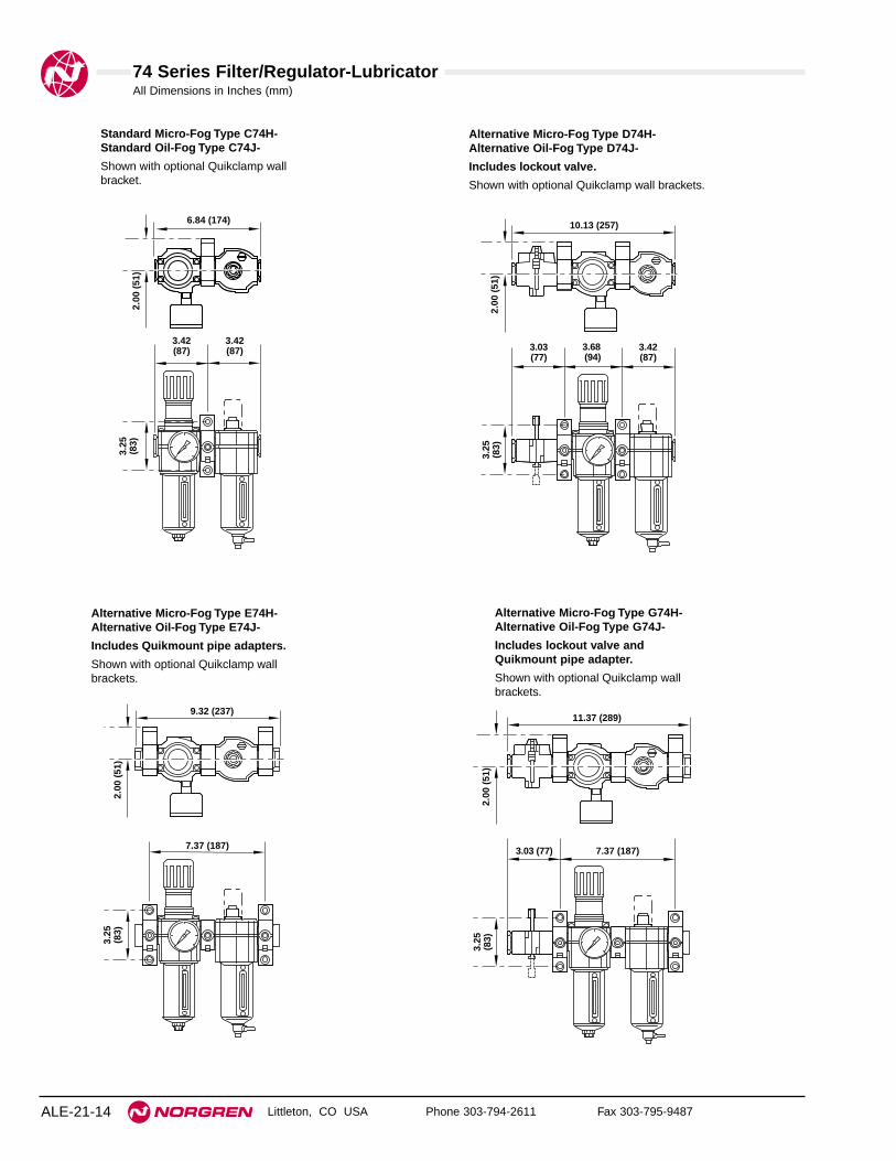
74 Series Filter/Regulator-Lubricator
Littleton, CO USA Phone 303-794-2611 Fax 303-795-9487ALE-21-14
All Dimensions in Inches (mm)
Standard Micro-Fog Type C74H-Standard Oil-Fog Type C74J-
Shown with optional Quikclamp wallbracket.
3.42(87)
3.42(87)
6.84 (174)
3.25
(83)
2.00
(51
)Alternative Micro-Fog Type D74H- Alternative Oil-Fog Type D74J-
Includes lockout valve.
Shown with optional Quikclamp wall brackets.
Alternative Micro-Fog Type E74H- Alternative Oil-Fog Type E74J-
Includes Quikmount pipe adapters.
Shown with optional Quikclamp wallbrackets.
7.37 (187)
9.32 (237)
3.25
(83)
2.00
(51
)
Alternative Micro-Fog Type G74H- Alternative Oil-Fog Type G74J-
Includes lockout valve andQuikmount pipe adapter.
Shown with optional Quikclamp wallbrackets.
3.68 (94)
3.03(77)
3.42(87)
10.13 (257)
3.25
(83)
2.00
(51
)
7.37 (187)3.03 (77)
11.37 (289)
3.25
(83)
2.00
(51
)

74 Series Filter/Regulator-Lubricator
Littleton, CO USA Phone 303-794-2611 Fax 303-795-9487 ALE-21-15
All Dimensions in Inches (mm)
9.20 (234)3.03 (77)
13.20 (335)
3.25
(83)
2.00
(51
)
Alternative Micro-Fog Type C74K- Alternative Oil-Fog Type C74L-
Includes porting block.
Shown with optional Quikclamp wallbrackets.
Alternative Micro-Fog Type D74K- Alternative Oil-Fog Type D74L-
Includes lockout valve and porting block.
Shown with optional Quikclamp wall brackets.
Alternative Micro-Fog Type E74K- Alternative Oil-Fog Type E74L-
Includes Quikmount pipe adaptersand porting block.
Shown with optional Quikclamp wallbrackets.
9.20 (234)
11.16 (283)
3.25
(83)
2.00
(51
)
3.42(87)
3.42(87)
1.85(47)
8.69 (221)
3.25
(83)
2.00
(51
)
3.03(77)
3.42(87)5.52 (140)
11.97 (304)
3.25
(83)
2.00
(51
)
Alternative Micro-Fog Type G74K- Alternative Oil-Fog Type G74L-
Includes lockout valve,Quikmount pipe adapter,and porting block.Shown with optional Quikclamp wallbrackets.

See Section ALE-25 for Accessories
Littleton, CO USA Phone 303-794-2611 Fax 303-795-9487
BL64 Olympian Plus Combination Units
● Olympian Plus plug in design
● High Efficiency water and particle removal
● Quick release bayonet bowls
● High visibility prismatic sight glass
● Push to lock adjusting knob with tamper resistantoption
● Constant oil density output with varying flow
Filter/Regulator-Lubricator1/4", 3/8", 1/2", and 3/4" Port Sizes
ALE-21-16
Technical DataFluid: Compressed airMaximum pressure:
Transparent bowl: 150 psig (10 bar)Metal bowl: 250 psig (17 bar)
Operating temperature*:Transparent bowl: 0° to 125°F (-20° to 50°C)Metal bowl: 0° to 175°F (-20° to 80°C)
* Air supply must be dry enough to avoid ice formation at temperatures below 35°F(2°C).
Particle removal: 5 µm, 25 µm, or 40 µm filter elementManual drain connection: Will fit 1/8-27 and 1/8-28 pipe threadAutomatic drain connection: Will fit 1/8-27 and 1/8-28 pipe threadAutomatic drain operating conditions (float operated):
Bowl pressure required to close drain: Greater than 5 psig(0.3 bar)
Bowl pressure required to open drain: Less than 3 psig (0.2 bar)Minimum air flow required to close drain: 2 scfm (1 dm3/s) Manual operation: Depress pin inside drain outlet to drain bowl
Nominal bowl size:Standard: 7 fluid ounce (0.2 liter)Optional size for lubricator: 1 quart (1 liter)
Gauge Ports:1/4" PTF with PTF main portsRc 1/8 with ISO Rc main portsRc 1/8 with ISO G main ports
Recommended lubricants: See Section ALE-29.Materials:
Body and yoke: ZincBonnet: AluminumFilter/Regulator valve: BrassBowl:
Transparent: PolycarbonateMetal: Aluminum
Metal bowl liquid level indicator lens:7 fluid ounce (0.2 liter): Transparent nylon1 quart (1 liter): Pyrex
Sight-Feed dome: PolycarbonateElement: Sintered polypropyleneElastomers: Neoprene and nitrile
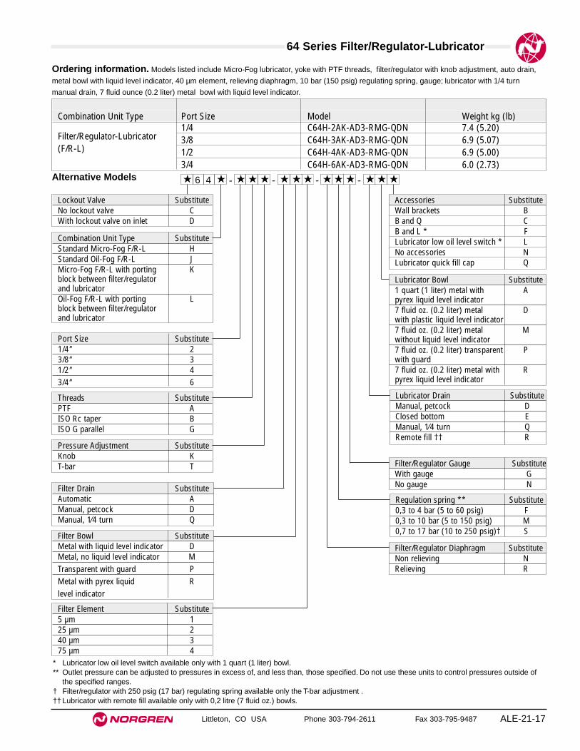
64 Series Filter/Regulator-Lubricator
Littleton, CO USA Phone 303-794-2611 Fax 303-795-9487 ALE-21-17
Ordering information. Models listed include Micro-Fog lubricator, yoke with PTF threads, filter/regulator with knob adjustment, auto drain,
metal bowl with liquid level indicator, 40 µm element, relieving diaphragm, 10 bar (150 psig) regulating spring, gauge; lubricator with 1/4 turn
manual drain, 7 fluid ounce (0.2 liter) metal bowl with liquid level indicator.
Alternative Models
Threads SubstitutePTF AISO Rc taper BISO G parallel G
Filter Drain SubstituteAutomatic AManual, petcock DManual, 1⁄4 turn Q
Accessories SubstituteWall brackets BB and Q CB and L * FLubricator low oil level switch * LNo accessories NLubricator quick fill cap Q
Pressure Adjustment SubstituteKnob KT-bar T
Filter Element Substitute5 µm 125 µm 240 µm 375 µm 4
Combination Unit Type SubstituteStandard Micro-Fog F/R-L HStandard Oil-Fog F/R-L JMicro-Fog F/R-L with porting Kblock between filter/regulatorand lubricatorOil-Fog F/R-L with porting Lblock between filter/regulatorand lubricator
Port Size Substitute1/4" 23/8" 31/2" 43/4" 6
★ - ★★ ★6 4 -★★ ★ ★ - ★★ ★ - ★★ ★
Lockout Valve SubstituteNo lockout valve CWith lockout valve on inlet D
Lubricator Bowl Substitute1 quart (1 liter) metal with Apyrex liquid level indicator7 fluid oz. (0.2 liter) metal Dwith plastic liquid level indicator7 fluid oz. (0.2 liter) metal Mwithout liquid level indicator7 fluid oz. (0.2 liter) transparent Pwith guard7 fluid oz. (0.2 liter) metal with Rpyrex liquid level indicator
Filter/Regulator Gauge SubstituteWith gauge GNo gauge N
Filter Bowl SubstituteMetal with liquid level indicator DMetal, no liquid level indicator MTransparent with guard PMetal with pyrex liquid Rlevel indicator
Combination Unit Type Port Size Model Weight kg (lb)
Filter/Regulator-Lubricator1/4 C64H-2AK-AD3-RMG-QDN 7.4 (5.20)
(F/R-L)3/8 C64H-3AK-AD3-RMG-QDN 6.9 (5.07)1/2 C64H-4AK-AD3-RMG-QDN 6.9 (5.00)3/4 C64H-6AK-AD3-RMG-QDN 6.0 (2.73)
Lubricator Drain SubstituteManual, petcock DClosed bottom EManual, 1⁄4 turn QRemote fill †† R
Regulation spring ** Substitute0,3 to 4 bar (5 to 60 psig) F0,3 to 10 bar (5 to 150 psig) M0,7 to 17 bar (10 to 250 psig)† S
Filter/Regulator Diaphragm SubstituteNon relieving NRelieving R
* Lubricator low oil level switch available only with 1 quart (1 liter) bowl.** Outlet pressure can be adjusted to pressures in excess of, and less than, those specified. Do not use these units to control pressures outside of
the specified ranges.† Filter/regulator with 250 psig (17 bar) regulating spring available only the T-bar adjustment .†† Lubricator with remote fill available only with 0,2 litre (7 fluid oz.) bowls.

Filter/Regulator-Lubricator
Littleton, CO USA Phone 303-794-2611 Fax 303-795-9487ALE-21-18
All Dimensions in Inches (mm)
9.1 (233) [G3/4 10.3 (262)]
1.44
(37
)
4.9
(125
)†
7.28 (185) [G3/4 9.33 (237)]
2.9
(74)
Au
to D
rain
11.
9 (3
03)†
Man
ual
Dra
in 1
2.2
(310
)†
† Reduces by .16 (4mm) with knob in locked position. Add .15 (37mm) for unit with T-handle.
Au
to D
rain
11.
3 (2
87)†
Man
ual
Dra
in 1
1.6
(294
)†
Item Type Part numberService kit Relieving Filter-Regulator 4383-200Service kit Non-relieving Filter-Regulator 4383-201Service kit Lubricator 4382-200
5 µm 4338-01Replacement elements 25 µm 4338-99
40 µm 4338-02
Replacement sightB64, plastic 4380-040
glassL64, plastic 4380-042B64 and L64, Pyrex 4380-041L64, 1 quart bowl, Pyrex 2273-22
Replacement drainsAutomatic 3000-10Manual, 1/4 turn 619-50
Service Kits
Filter-Regulator service kit includes port seals, louver ‘O’ ring, bowl ‘O’ ringand drain gasket, slip ring, valve assembly, valve spring and diaphragm.Lubricator service kit includes all seals, flow sensor, eyelet, dome screen,ball and spring.

Littleton, CO USA Phone 303-794-2611 Fax 303-795-9487 ALE-22-1
Section 22
Filter-Regulator-Lubricator Combination units in ports sizesfrom 1/8" to 1-1/2".
07 Series Filter-Regulator-Lubricator Combination Units 1/8" and 1/4" port sizes . . . . . . . . .ALE-22-2
Excelon 72 Filter-Regulator-Lubricator Combination Units 1/4" and 3/8" port sizes . . . . . . . . .ALE-22-4
Excelon 73 Filter-Regulator-Lubricator Combination Units 1/4", 3/8", and 1/2" port sizes . . . . . . . . . . . . . . . .ALE-22-8
Excelon 74 Filter-Regulator-Lubricator Combination Units 3/8", 1/2", and 3/4" port sizes . . . . . . . . . . . . . . .ALE-22-12
17 Series Filter-Regulator-Lubricator Combination Units 3/4", 1", 1-1/4", and 1-1/2" Port Sizes . . . . . . . . .ALE-23-16
Olympian 64 Filter-Regulator-Lubricator Combination Units 1/4, 3/8", 1/2", and 3/4" Port Sizes . . . . . . . . . . .ALE-22-18
07 SeriesF-R-L
72 SeriesF-R-L
73 SeriesF-R-L
74 SeriesF-R-L
64 SeriesF-R-L
17 SeriesF-R-L

See Section ALE-25 for Accessories
Littleton, CO USA Phone 303-794-2611 Fax 303-795-9487
P1A Combination Unit
● Compact design
● Filter removes liquids and solid particles down to5 µm
● Push to lock adjusting knob with tamper resistantoption
● Micro-Fog lubricator provides air line lubrication toone or more air driven tools or other devices
● Nearly constant oil density output with varying airflow
● Can be disassembled without the use of tools orremoval from the air line
07 Series Filter-Regulator-Lubricator 1/8" and 1/4" Port Sizes
ALE-22-2
Ordering Information. Models listed include PTF threads, transparent bowls, filter with automatic drain, 5 µm element; regulator withrelieving diaphragm, 5 to 100 psig (0.3 to 7 bar) outlet pressure adjustment range*, gauge; lubricator with manual drain.
Alternative Models - ★★★ ★★ ★ -1 ★P A
Threads SubstitutePTF AISO Rc taper BISO G parallel G
Filter Drain SubstituteAutomatic AManual M
Port Size Substitute1/8" 11/4" 2
Filter Element Substitute5 µm 1100 µm 5
Lubricator Reservoir SubstituteTransparent with drain ATransparent without drain QMetal with drain MMetal without drain F
* Outlet pressure can be adjusted to pressures in excess of, and less than, those specified. Do not use these units to control pressures outsideof the specified ranges.
Outlet PressureAdjustment Range* Relief
Filter Bowl psig bar Type Gauge SubstituteTransparent 5 to 100 0.3 to 7 Relieving With 00Transparent 5 to 100 0.3 to 7 Relieving Without 01Transparent 5 to 100 0.3 to 7 Non-relieving Without 02Transparent 5 to 100 0.3 to 7 Non-relieving With 03Transparent 5 to 50 0.3 to 3.5 Relieving Without 04Transparent 5 to 50 0.3 to 3.5 Relieving With 05Transparent 5 to 50 0.3 to 3.5 Non-relieving Without 06Transparent 5 to 50 0.3 to 3.5 Non-relieving With 07Metal / no sight glass 5 to 100 0.3 to 7 Relieving With 40Metal / no sight glass 5 to 100 0.3 to 7 Relieving Without 41Metal / no sight glass 5 to 100 0.3 to 7 Non-relieving Without 42Metal / no sight glass 5 to 100 0.3 to 7 Non-relieving With 43Metal / no sight glass 5 to 50 0.3 to 3.5 Relieving Without 44Metal / no sight glass 5 to 50 0.3 to 3.5 Relieving With 45Metal / no sight glass 5 to 50 0.3 to 3.5 Non-relieving Without 46Metal / no sight glass 5 to 50 0.3 to 3.5 Non-relieving With 47
Port Size Model Numbers Weight lbs (kg)1/8" P1A-100-A1AA 1.17 (0.53)1/4" P1A-200-A1AA 1.17 (0.53)

Miniature 07 Series Filter-Regulator-Lubricator
Littleton, CO USA Phone 303-794-2611 Fax 303-795-9487 ALE-22-3
All Dimensions in Inches (mm)
ISO Symbols
Filter with automatic drain, relievingregulator, lubricator with manual drain.
Technical DataFluid: Compressed airMaximum pressure
Transparent bowl: 150 psig (10 bar)Metal bowl: 250 psig (17 bar)
Operating temperature*Transparent bowl: 0° to 125°F (-20° to 50°C)Metal bowl: 0° to 150°F (-20° to 65°C)
* Air supply must be dry enough to avoid ice formation at temperatures below 35°F (2°C)Drain connection: Will fit 1/8-27 and 1/8-28 pipe threadFilterPartical removal: 5 µm or 40 µm. Within ISO 8573-1, Class 3 and Class 5Automatic drain operation: Spitter type drain operates momentarily when a rapid
change in air flow occurs or when the supply pressure is reduced.RegulatorRecommended regulating pressure ranges†:
5 to 100 psig (0.3 to 7 bar) standard5 to 50 psig (0.3 to 3.5 bar) optional
† Outlet pressures can be adjusted to pressures in excess of, and less than those specified.Do not use these units to control pressures outside of the specified ranges.
Gauge ports:1/8" PTF with PTF main ports1/8" ISO Rc with ISO Rc main ports1/8" ISO Rc with ISO G main ports
LubricatorStart point (i.e. minimum flow required for lubricator operation): 0.5 scfm (0.24
dm3/s) at 90 psig (6.3 bar) inlet pressureNominal bowl size: 1 fluid ounce (31 ml)Recommended lubricants: See Section ALE-29.Materials
Bodies: ZincFilter/Regulator bonnet: AcetalFilter/Regulator valve: Brass/nitrileFilter/Regulator valve seat: AcetalBowls
Transparent: PolycarbonateMetal: Zinc
Lubricator sight-feed dome: Transparent nylonFilter element: Sintered polypropyleneElastomers: Nitrile
2.13
(54
)
5.47 (139)
1.50 (38)
0.38
(10)
2.52
(64
)
3.72
(94
) A
uto
mat
ic D
rain
3.87
(98
) M
anu
al D
rain
1.50
(38
)
0.95
(24)
0.38
(10
)
1.65
(42
)3.
07 (
78)
Wit
ho
ut
Dra
in
8.31
(21
1)*
* Minimum clearance to remove bowl.** Use 2" (51 mm) long screws, 5/32" diameter, to mount PTA Unit to wall.

See Section ALE-25 for Accessories
Littleton, CO USA Phone 303-794-2611 Fax 303-795-9487
F72G, R72, L72 Combination Units
● True modularity with Norgren Quikclamp™connections
● Quick release bayonet bowl
● Lubricator flow sensor provides a nearly constantoil/air ratio over a wide range of air flows
● All around (360°) visibility of the lubricator sight-feeddome simplifies installation and adjustment
● Regulator balanced valve minimizes effect of variationin the inlet pressure on the outlet pressure
Use Micro-Fog models in applications containing one or morepoints of lubrication.Use Oil-Fog models to lubricate a single tool, cylinder, or other airdriven device.
Excelon 72 Filter-Regulator-Lubricator1/4" and 3/8" Port Sizes
Technical DataFluid: Compressed airMaximum pressure
Transparent bowl: 150 psig (10 bar)Metal bowl (Manual or semi automatic drain): 250 psig (17 bar)Automatic drain: 150 psig (10 bar)
Operating temperature*Transparent bowl: 0° to 125°F (-20° to 50°C)Metal bowl: 0° to 150°F (-20° to 65°C)
* Air supply must be dry enough to avoid ice formation at temperatures below 35°F (2°C).
Particle removal: 5 µm, 25 µm, or 40 µm filter elementManual drain connection: Will fit 1/8-27 and 1/8-28 pipe threadSemi automatic drain connection: Push on 5/16" (8 mm) ID tubeSemi automatic drain operating conditions (pressure operated)
Bowl pressure required to close drain: Greater than 1.5 psig (0.1 bar)Bowl pressure required to open drain: Less than 1.5 psig (0.1 bar) Minimum air flow required to close drain: 1 scfm (0.5 dm3/s)Manual operation: Lift stem to drain bowl
Automatic drain connection: Will fit 1/8-27 and 1/8-28 pipe threadAutomatic drain operating conditions (float operated)
Bowl pressure required to close drain: Greater than 5 psig (0.3 bar) Bowl pressure required to open drain: Less than 3 psig (0.2 bar)Minimum air flow required to close drain: 0.2 scfm (0.1 dm3/s)Manual operation: Depress pin inside drain outlet to drain bowl
Nominal bowl size Short bowl: 1.9 fluid ounce (56 ml)Long bowl: 2.2 fluid ounce (65 ml)
Gauge ports: 1/8 PTF with PTF main portsRc1/8 with ISO Rc main portsRc1/8 with ISO G main ports
Recommended lubricants: See Section ALE-29.Materials
Body: ZincBonnet: AcetalRegulator valve: BrassRegulator bottom plug: AcetalBowl
Transparent: PolycarbonateTransparent with guard: Polycarbonate, zinc guardMetal: ZincMetal bowl liquid level indicator lens: Transparent nylon
Sight-Feed dome: Transparent nylonElement: Sintered polypropyleneElastomers: Neoprene, nitrile
ALE-22-4
ISO Symbols
Filter with automatic drain, relieving regulator,lubricator with manual drain.

F72G-R72-L72 Combination Unit
Littleton, CO USA Phone 303-794-2611 Fax 303-795-9487 ALE-22-5
Ordering information. Models listed include PTF threads. Filter (F) includes automatic drain, long transparent bowl without guard, and a
40µm element. Regulator (R) is relieving type with knob adjustment, 150 psig (10 bar) regulating spring, and gauge. Lubricator (L) is a Micro-Fog
model with 1/4 turn manual drain and long transparent bowl without guard.
Alternative Models
Threads SubstitutePTF AISO Rc taper BISO G parallel G
Filter Drain SubstituteAutomatic † AManual, 1⁄4 turn QSemi automatic S
Pressure Adjustment SubstituteKnob KT-bar T
Filter Element Substitute5 µm 125 µm 240 µm 3
Combination Unit Type SubstituteMicro-Fog F-R-L AOil-Fog F-R-L B
Port Size Substitute1/4" 23/8" 3
★ - ★★ ★7 2 -★★ ★ ★ - ★★ ★ - ★★ ★
Regulator Gauge SubstituteWith gauge GNo gauge N
Combination Unit Type Port Size Model Weight lb (kg)Filter-Regulator-Lubricator 1/4" C72A-2AK-AL3-RMG-QLN 3.23 (1.47)(F-R-L) 3/8" C72A-3AK-AL3-RMG-QLN 3.23 (1.47)
Regulation spring ** Substitute5 to 30 psig (0.3 to 2 bar) C5 to 60 psig (0.3 to 4 bar) F5 to 150 psig (0.3 to 10 bar) M
Regulator Diaphragm SubstituteNon-relieving NRelieving R
Lubricator Drain SubstituteClosed bottom EManual, 1⁄4 turn Q
** Outlet pressure can be adjusted to pressures in excess of, and less than, those specified. Do not use these units to control pressures outside of the specified ranges.† Supplied in long bowl options only.
Shutoff/Lockout Valve, Quikmount SubstituteStandard Combination (No CShutoff/Lockout Valve, no Quikmount)With Shutoff/Lockout valve on inlet DWith Quikmount pipe adapters Eon inlet and outletWith Shutoff/Lockout Valve on inlet Gand Quikmount pipe adapter on outlet
Accessories SubstituteQuikclamp wall brackets BNo accessories N
Lubricator Bowl SubstituteShort metal with liquid level indicator DLong metal with liquid level indicator EShort transparent without guard TLong transparent without guard LLong transparent with guard W
Filter Bowl SubstituteShort metal with liquid level indicator DLong metal with liquid level indicator EShort transparent without guard TLong transparent without guard LLong transparent with guard W

F72G-R72-L72 Combination Unit
Littleton, CO USA Phone 303-794-2611 Fax 303-795-9487ALE-22-6
All Dimensions in Inches (mm)
Standard Micro-Fog Type C72A-Standard Oil-Fog Type C72B-
Shown with optiona Quikclamp wallbracket.
Alternative Micro-Fog Type D72A- Alternative Oil-Fog Type D72B-
Includes Shutoff/Lockout valve.
Shown with optional Quikclamp wallbrackets.
2.32
(59
)
6.46 (164)
2.24(56)
2.11(54)
2.11(54)
1.50
(38)
2.32
(59
)
4.48 (113)2.11(54)
2.11(54)
1.50
(38)
8.70 (221)

F72G-R72-L72 Combination Unit
Littleton, CO USA Phone 303-794-2611 Fax 303-795-9487 ALE-22-7
All Dimensions in Inches (mm)
Alternative Micro-Fog Type E72A- Alternative Oil-Fog Type E72B-
Includes Quikmount pipe adapters.
Shown with optional gauge andQuikclamp wall brackets.
6.72 (171)
2.32
(59
) 1.
50(3
8)
8.24 (209)
6.72 (171)2.11(54)
2.32
(59
) 1.
50(3
8)
9.59 (244)Alternative Micro-Fog Type G72A- Alternative Oil-Fog Type G72B-
Includes Shutoff/Lockout valve and Quikmount pipe adapter.Shown with optional gauge and Quikclamp wall brackets.

See Section ALE-25 for Accessories
Littleton, CO USA Phone 303-794-2611 Fax 303-795-9487
F73G, R73, L73 Combination Units
● True modularity with Norgren Quikclamp™connections
● Quick release bayonet bowl
● Lubricator flow sensor provides a nearly constantoil/air ratio over a wide range of air flows
● All around (360°) visibility of the lubricator sight-feeddome simplifies installation and adjustment
● Regulator balanced valve minimizes effect of variationin the inlet pressure on the outlet pressure
Use Micro-Fog models in applications containing one or morepoints of lubrication.Use Oil-Fog models to lubricate a single tool, cylinder, or other airdriven device.
Excelon 73 Filter-Regulator-Lubricator 1/4", 3/8", 1/2" Port Sizes
Technical DataFluid: Compressed airMaximum pressure
Transparent bowl: 150 psig (10 bar)Metal bowl: 250 psig (17 bar)
Operating temperature*Transparent bowl: 0° to 125°F (-20° to 50°C)Metal bowl: 0° to 175°F (-20° to 80°C)
* Air supply must be dry enough to avoid ice formation at temperatures below 35°F (2°C).
Particle removal: 5 µm, 25 µm, or 40 µm filter elementManual drain connection: Will fit 1/8-27 and 1/8-28 pipe threadAutomatic drain connection: Will fit 1/8-27 and 1/8-28 pipe threadAutomatic drain operating conditions (float operated)
Bowl pressure required to close drain: Greater than 5 psig (0.3 bar)Bowl pressure required to open drain: Less than 3 psig (0.2 bar)Minimum air flow required to close drain: 0.2 scfm (0.1 dm3/s) Manual operation: Depress pin inside drain outlet to drain bowl
Nominal bowl size: 3.5 fluid ounce (0.1 liter)Gauge ports:
1⁄4 PTF with PTF main portsISO Rc1/4 with ISO Rc main portsISO Rc1/8 with ISO G main ports
Recommended lubricants: See Section ALE-29.Materials
Body: AluminumBonnet: Aluminum or ZincRegulator valve: BrassRegulator bottom plug: AcetalBowl
Transparent: PolycarbonateTransparent with guard: Polycarbonate, steel guardMetal: AluminumMetal bowl liquid level indicator lens: Transparent nylon
Sight-Feed dome: Transparent nylonElement: Sintered plasticElastomers: Neoprene and nitrile
ALE-22-8
ISO Symbols
Filter with automatic drain, relieving regulator,lubricator with manual drain.

F73G-R73-L73 Combination Unit
Littleton, CO USA Phone 303-794-2611 Fax 303-795-9487 ALE-22-9
Ordering information
Models listed in order table have PTF threads. Filter (F) has automatic drain, metal bowl with liquid level indicator, and a 40 µm element.
Regulator (R) has knob adjustment, relieving diaphragm, 150 psig (10 bar) regulating spring, and gauge. Lubricator (L) is a Micro-Fog model with
1/4 turn manual drain and metal bowl with liquid level indicator.
Alternative Models
Threads SubstitutePTF AISO Rc taper BISO G parallel G
Filter Drain SubstituteAutomatic AManual, 1⁄4 turn Q
Pressure Adjustment SubstituteKnob KT-bar T
Filter Element Substitute5 µm 125 µm 240 µm 3
Combination Unit Type SubstituteMicro-Fog F-R-L AOil-Fog F-R-L B
Port Size Substitute1/4" 23/8" 31/2" 4
★ - ★★ ★7 3 -★★ ★ ★ - ★★ ★ - ★★ ★
Lockout Valve/ Quikmount SubstituteStandard Combination (No CLockout Valve, no Quikmount)With Lockout valve on inlet DWith Quikmount pipe adapters Eon inlet and outletWith Lockout valve on inlet and GQuikmount pipe adapter onoutlet
Regulator Gauge SubstituteWith gauge GNo gauge N
Combination Unit Type Port Size Model Weight lb (kg)
Filter-Regulator-Lubricator1/4" C73A-2AK-AD3-RMG-QDN 4.36 (1.98)
(F-R-L)3/8" C73A-3AK-AD3-RMG-QDN 4.36 (1.98)1/2" C73A-4AK-AD3-RMG-QDN 4.36 (1.98)
Regulation spring * Substitute5 to 60 psig (0.3 to 4 bar) F5 to 150 psig (0.3 to 10 bar) M10 to 250 psig (0.7 to 17 bar)** S
Regulator Diaphragm SubstituteNon-relieving NRelieving R
Filter Bowl SubstituteMetal with liquid level indicator DTransparent with steel guard PTransparent T
Lubricator Bowl SubstituteMetal with liquid level indicator DTransparent with guard PTransparent T
Lubricator Drain SubstituteClosed bottom EManual, 1⁄4 turn Q
Accessories SubstituteAccessories B and D AQuikclamp wall brackets BAccessories B and Q CFilter service indicator DAccessories B, D, and Q HNo accessories NLubricator quick fill nipple Q
* Outlet pressure can be adjusted to pressures in excess of, and less than, those specified. Do not use these units to control pressures outside of the specified ranges.
** Units with 250 psig (17 bar) outlet pressure range are available only with the standard metal bowl.
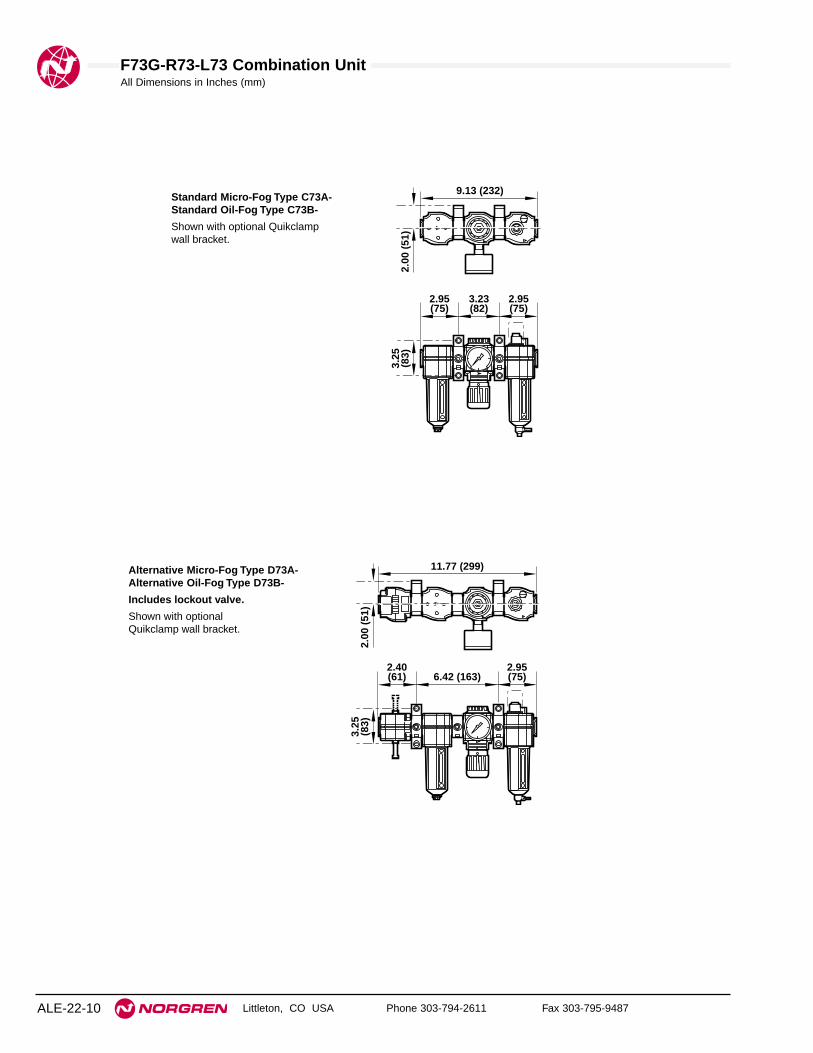
F73G-R73-L73 Combination Unit
Littleton, CO USA Phone 303-794-2611 Fax 303-795-9487ALE-22-10
All Dimensions in Inches (mm)
11.77 (299)
2.40(61)
2.95(75)6.42 (163)
3.25
(83)
2.00
(51
)
Standard Micro-Fog Type C73A-Standard Oil-Fog Type C73B-
Shown with optional Quikclampwall bracket.
9.13 (232)
2.95(75)
2.95(75)
3.23(82)
3.25
(83)
2.00
(51
)
Alternative Micro-Fog Type D73A- Alternative Oil-Fog Type D73B-
Includes lockout valve.
Shown with optional Quikclamp wall bracket.

F73G-R73-L73 Combination Unit
Littleton, CO USA Phone 303-794-2611 Fax 303-795-9487 ALE-22-11
All Dimensions in Inches (mm)
11.57 (294)
9.65 (245)
3.25
(83)
2.00
(51
)
12.99 (330)
9.65 (245)2.40(61)
3.25
(83)
2.00
(51
)
Alternative Micro-Fog Type E73A- Alternative Oil-Fog Type E73B-
Includes Quikmount pipe adapters.
Shown with optionalQuikclamp wall bracket.
Alternative Micro-Fog Type G73A- Alternative Oil-Fog Type G73B-
Includes lockout valve and Quikmount pipe adapter.
Shown with optional Quikclamp wall bracket.

Littleton, CO USA Phone 303-794-2611 Fax 303-795-9487
F74G, R74, L74 Combination Units
● True modularity with Norgren Quikclamp™connections
● Quick release bayonet bowl
● Lubricator flow sensor provides a nearly constantoil/air ratio over a wide range of air flows
● All around (360°) visibility of the lubricator sight-feeddome simplifies installation and adjustment
● Regulator balanced valve minimizes effect of variationin the inlet pressure on the outlet pressure
Use Micro-Fog models in applications containing one or morepoints of lubrication.Use Oil-Fog models to lubricate a single tool, cylinder, or other airdriven device.
Excelon 74 Filter-Regulator-Lubricator3/8", 1/2", 3/4" Port Sizes
Technical DataFluid: Compressed airMaximum pressure
Transparent bowl: 150 psig (10 bar)Metal bowl: 250 psig (17 bar)
Operating temperature* Transparent bowl: 0° to 125°F (-20° to 50°C)Metal bowl: 0° to 175°F (-20° to 80°C)
* Air supply must be dry enough to avoid ice formation at temperatures below 35°F (2°C).Particle removal: 5 µm, 25 µm, or 40 µm filter elementManual drain connection: Will fit 1/8-27 and 1/8-28 pipe threadAutomatic drain connection: Will fit 1/8-27 and 1/8-28 pipe threadAutomatic drain operating conditions (float operated)
Bowl pressure required to close drain: Greater than 5 psig (0.3 bar)Bowl pressure required to open drain: Less than 3 psig (0.2 bar)Minimum air flow required to close drain: 2 scfm (1 dm3/s) Manual operation: Depress pin inside drain outlet to drain bowl
Nominal bowl size:Standard: 7 fluid ounce (0.2 liter)Optional size for lubricator: 1 quart US (1 liter)
Gauge Ports:1/4" PTF with PTF main portsRc 1/4 with ISO Rc main portsRc 1/8 with ISO G main ports
Recommended lubricants: See Section ALE-29.Materials
Body: AluminumBonnet: AluminumRegulator valve: BrassRegulator bottom plug: AcetalBowl
Transparent: Polycarbonate with steel bowl guardMetal: Aluminum
Metal bowl liquid level indicator lens:7 fluid ounce (0.2 liter): Transparent nylon1 quart US (1 liter): Pyrex
Sight-Feed dome: Transparent nylonElement: Sintered polypropyleneElastomers: Neoprene and nitrile
ALE-22-12
See Section ALE-25 for Accessories
ISO Symbols
Filter with automatic drain, relievingregulator, lubricator with manual drain.

F74G-R74-L74 Combination Unit
Littleton, CO USA Phone 303-794-2611 Fax 303-795-9487 ALE-22-13
Ordering information. Models listed include Micro-Fog lubricator, PTF threads, knob pressure adjustment, metal filter bowl with liquid level
indicator and automatic drain, 40 µm filter element, relieving diaphragm, 150 psig (10 bar) regulating spring, gauge, 7 fluid oz. (0.2 liter) metal
lubricator bowl with liquid level indicator and 1/4 turn manual drain.
Alternative Models
Threads SubstitutePTF AISO Rc taper BISO G parallel G
Filter Drain SubstituteAutomatic AManual, 1⁄4 turn Q
Accessories SubstituteQuikclamp wall brackets Aand filter service indicatorQuikclamp wall brackets BQuikclamp wall brackets Cand lubricator quick fill nippleFilter service indicator DQuikclamp wall brackets, Hfilter service indicator and lubricator quick fill nippleNo accessories NLubricator quick fill nipple Q
Pressure Adjustment SubstituteKnob KT-bar T
Filter Element Substitute5 µm 125 µm 240 µm 3
Combination Unit Type SubstituteMicro-Fog F-R-L AOil-Fog F-R-L B
Port Size Substitute3/8" 31/2" 43/4" 6
★ - ★★ ★7 4 -★★ ★ ★ - ★★ ★ - ★★ ★
Lockout Valve/ Quikmount SubstituteStandard combination (no Clockout valve or Quikmount)With lockout valve on inlet DWith Quikmount pipe adapters Eon inlet and outletWith Lockout valve on inlet and GQuikmount pipe adapter onoutlet
Lubricator Bowl Substitute1 quart US (1 liter) metal with Aliquid level indicator7 fluid oz. (0.2 liter) metal Dwith liquid level indicator7 fluid oz. (0.2 liter) transparent Pwith zinc guard
Regulator Gauge SubstituteWith gauge GNo gauge N
Filter Bowl SubstituteMetal with liquid level indicator DTransparent with guard P
Combination Unit Type Port Size Model Weight lb (kg)
Filter-Regulator-Lubricator3/8" C74A-3AK-AD3-RMG-QDN 6.22 (2.82)
(F-R-L)1/2" C74A-4AK-AD3-RMG-QDN 6.04 (2.74)3/4" C74A-6AK-AD3-RMG-QDN 5.91 (2.68)
Lubricator Drain SubstituteClosed bottom EManual, 1⁄4 turn QRemote fill †† R
Regulation spring ** Substitute5 to 60 psig (0.3 to 4 bar) F5 to 150 psig (0.3 to 10 bar) M10 to 250 psig (0.7 to 17 bar)† S
Regulator Diaphragm SubstituteNon relieving NRelieving R
** Outlet pressure can be adjusted to pressures in excess of,and less than, those specified. Do not use these units tocontrol pressures outside of the specified ranges.
† Units with 250 psig (17 bar) outlet pressure range areavailable only with the T-bar adjustment; therefore substituteT at the 7th position and S at the 12th position.
†† Use remote fill only with 7 fluid oz. (0.2 liter) bowls.

F74G-R74-L74 Combination Unit
Littleton, CO USA Phone 303-794-2611 Fax 303-795-9487ALE-22-14
All Dimensions in Inches (mm)
Standard Micro-Fog Type C74A- Standard Oil-Fog Type C74B-
Shown with optional Quikclampwall bracket.
10.52 (267)
3.42(87)
3.42(87)
3.68(94)
3.25
(83)
2.00
(51
)
Alternative Micro-Fog Type D74A- Alternative Oil-Fog Type D74B-
Includes Shutoff/Lockout valve.
Shown with optional Quikclamp wallbrackets.
13.81 (351)
3.03(77)
3.42(87)7.37 (187)
3.25
(83)
2.00
(51
)

F74G-R74-L74 Combination Unit
Littleton, CO USA Phone 303-794-2611 Fax 303-795-9487 ALE-22-15
All Dimensions in Inches (mm)
Alternative Micro-Fog Type E74A- Alternative Oil-Fog Type E74B-
Includes Quikmount pipe adapters.
Shown with optional Quikclamp wallbrackets.
13.00 (330)
11.05 (281)
3.25
(83)
2.00
(51
)
Alternative Micro-Fog Type G74A- Alternative Oil-Fog Type G74B-
Includes Shutoff/Lockout valveand Quikmount pipe adapter.
Shown with optional Quikclamp wallbrackets.
15.05 (382)
11.05 (281)3.03(77)
3.25
(83)
2.00
(51
)

See Section ALE-25 for Accessories
Littleton, CO USA Phone 303-794-2611 Fax 303-795-9487
P8A, P8B Combination Units
● Depth type, 40 µm filter element
● Balanced regulator valve minimizes effect ofchanges in inlet pressure on outlet pressure
● Low torque, non-rising regulator pressure adjustingknob
● All around (360°) visibility of the lubricator sight-feeddome simplifies installation and adjustment
● Lubricator flow sensor provides a nearly constantoil/air ratio over a wide range of air flows
Use Micro-Fog combinations in applications containing one ormore points of lubrication
Use Oil-Fog combinations to lubricate a single tool, cylinder, orother air driven device
17 Series Filter-Regulator-Lubricator3/4", 1", 1-1/4" and 1-1/2" Port Sizes
ALE-22-16
ISO Symbols
Filter with automatic drain, relievingregulator, lubricator with manual drain
Technical DataFluid: Compressed airMaximum pressure: 250 psig (17 bar)Operating temperature*: 0° to 175°F (-20° to 80°C)* Air supply must be dry enough to avoid ice formation at temperatures below 35°F (2°C).Start point (minimum flow required for lubricator operation): 8 scfm (3.8 dm3/s) at
90 psig (6.3 bar) inlet pressureRegulator gauge ports:
1/4" PTF with PTF main portsR1/4 with ISO Rc, ISO G, and BSPP main ports
Nominal bowl size: 1 quart US (1 liter)Manual drain connection: Will fit 1/8-27 and 1/8-28 pipe threadAutomatic drain connection: Will fit 1/8-27 and 1/8-28 pipe threadAutomatic drain operating conditions (float operated)
Bowl pressure required to close drain: Greater than 5 psig (0.3 bar)Bowl pressure required to open drain: Less than 3 psig (0.2 bar)Minimum air flow required to close drain: 2 scfm (1 dm3/s) Manual operation: Depress pin inside drain outlet to drain bowl
Recommended lubricants: See Section ALE-29.Materials
Bodies, bowls, regulator bonnet: AluminumBowl sight glass: PyrexFilter element: Sintered bronzeRegulator bottom plug: AcetalRegulator valve: Aluminum and nylonLubricator sight-feed dome: Transparent nylonElastomers: Neoprene and nitrile

17 Series F-R-L Combination Unit
Littleton, CO USA Phone 303-794-2611 Fax 303-795-9487 ALE-22-17
All Dimensions in Inches (mm)
Alternative Models - ★★★ ★★ ★ -8 ★★ ★
Threads SubstitutePTF AISO Rc taper BBSPP (1-1/2" ported units only) CISO G parallel (not available Gwith 1-1/2" ported units)
Lubricator Type SubstituteMicro-Fog AOil-Fog B
Port Size Substitute3/4" 61" 81-1/4" A1-1/2" B
Filter Drain SubstituteAutomatic AManual M
Port Size Micro-Fog Models Oil-Fog Models Weight lbs (kg)3/4" P8A-660-A3DA P8B-660-A3DA 6.69 (3.03)1" P8A-860-A3DA P8B-860-A3DA 6.29 (2.85)1-1/4" P8A-A60-A3DA P8B-A60-A3DA 7.51 (3.41)1-1/2" P8A-B60-A3DA P8B-B60-A3DA 6.88 (3.12)
* Outlet pressure can be adjusted to pressures in excess of, and less than, those specified. Do not use these units to control pressures outside of the specified ranges.
Filter Element Substitute40 µm 3
Lubricator Reservoir Substitute1 quart US (1 liter) metal, drain, Dsight glass
Regulator Adjustment SubstituteT-bar HKnob P
Ordering Information. Models listed have PTF port threads . Filters and lubricators have metal bowl with sight glass. Filters have 40 µmelement and automatic drain. Lubricators have manual drain. Regulators are relieving type with gauge, knob adjustment, and outlet pressureadjustment range of 5 to 125 psig (0.3 to 8.5 bar)*.
Outlet PressureAdjustment Range* Relief
Filter Bowl psig bar Type Gauge SubstituteMetal, sight glass 5 to 125 0.3 to 8.5 Relieving With 60Metal, sight glass 5 to 125 0.3 to 8.5 Relieving Without 61Metal, sight glass 5 to 125 0.3 to 8.5 Non relieving Without 62Metal, sight glass 5 to 125 0.3 to 8.5 Non relieving With 63Metal, sight glass 5 to 50 0.3 to 3.5 Relieving Without 64Metal, sight glass 5 to 50 0.3 to 3.5 Relieving With 65Metal, sight glass 5 to 50 0.3 to 3.5 Non relieving Without 66Metal, sight glass 5 to 50 0.3 to 3.5 Non relieving With 67Metal, sight glass 10 to 250 0.7 to 17 Relieving Without 76Metal, sight glass 10 to 250 0.7 to 17 Relieving With 77Metal, sight glass 10 to 250 0.7 to 17 Non relieving Without 76Metal, sight glass 10 to 250 0.7 to 17 Non relieving With 79
* Minimum clearance required to remove bowl.
Manual Drain
10.4
(26
5)
2.38
(60)
Automatic Drain
16.9
(42
9)*
10.0
6 (2
56 )
2.40(61)
2.40(61)
4.32
(11
0)
14.75 (375)
2.92
(74)
Service KitsItem Type Part NumberLubricator service kit All o-rings, seals, gaskets 5771-02
Filter service kitAll o-rings, seals, gaskets 5578-0540 µm element 5311-03
Replacement drain Automatic 3000-10Sight glass kit * Pyrex 2273-22
Regulator service kit **Relieving 5578-02Non relieving 5578-01
Replacement drain 1/4 Turn 619-50
* Sight glass kit contains bowl o-ring plus all o-rings, seals, screws, glass, and glass guard.** Regulator service kit contains, diaphragm, all o-rings, valve, and valve spring.

See Section ALE-25 for Accessories
Littleton, CO USA Phone 303-794-2611 Fax 303-795-9487
64 Series F-R-L Combination Units
● Olympian Plus plug in design
● High Efficiency water and particle removal
● Quick release bayonet bowls
● High visibility prismatic sight glass
● Push to lock adjusting knob with tamper resistantoption
● Constant oil density output with varying flow
64 Series Filter-Regulator-Lubricator1/4", 3/8", 1/2", and 3/4" Port Sizes
Technical DataFluid: Compressed airMaximum pressure:
Transparent bowl: 150 psig (10 bar)Metal bowl: 250 psig (17 bar)
Operating temperature*:Transparent bowl: 0° to 125°F (-20° to 50°C)Metal bowl: 0° to 175°F (-20° to 80°C)
* Air supply must be dry enough to avoid ice formation at temperatures below 35°F (2°C).Particle removal: 5 µm, 25 µm, or 40 µm filter elementManual drain connection: Will fit 1/8-27 and 1/8-28 pipe threadAutomatic drain connection: Will fit 1/8-27 and 1/8-28 pipe threadAutomatic drain operating conditions (float operated):
Bowl pressure required to close drain: Greater than 5 psig(0.3 bar)
Bowl pressure required to open drain: Less than 3 psig (0.2 bar)Minimum air flow required to close drain: 2 scfm (1 dm3/s) Manual operation: Depress pin inside drain outlet to drain bowl
Nominal bowl size:Standard: 7 fluid ounce (0.2 liter)Optional size for lubricator: 1 quart (1 liter)
Gauge Ports:1/4" PTF with PTF main portsRc 1/8 with ISO Rc main portsRc 1/8 with ISO G main ports
Recommended lubricants: See Section ALE-29.Materials
Body and yoke: ZincBonnet: AluminumRegulator valve: BrassBowl:
Transparent: PolycarbonateMetal: Aluminum
Metal bowl liquid level indicator lens:7 fluid ounce (0.2 liter): Transparent nylon1 quart (1 liter): Pyrex
Sight-Feed dome: PolycarbonateElement: Sintered polypropyleneElastomers: Neoprene and nitrile
ALE-22-18

64 Series F-R-L Combination Unit
Littleton, CO USA Phone 303-794-2611 Fax 303-795-9487 ALE-22-19
Ordering information. Models listed include Micro-Fog lubricator, yoke with PTF threads, knob adjustment, filter with auto drain, metal bowl
with liquid level indicator, 40 µm element; regulator with relieving diaphragm, 10 bar (150 psig) regulating spring, gauge; lubricator with 1/4 turn
manual drain, 7 fluid ounce (0.2 liter) metal bowl with liquid level indicator.
Alternative Models
Threads SubstitutePTF AISO Rc taper BISO G parallel G
Filter Drain SubstituteAutomatic AManual, petcock DManual, 1⁄4 turn Q
Accessories SubstituteB and D AWall brackets BB and Q CFilter service indicator DB and L * FB, D, and Q HB, D, and L KLubricator low oil level switch * LNo accessories NLubricator quick fill cap Q
Pressure Adjustment SubstituteKnob KT-bar T
Filter Element Substitute5 µm 125 µm 240 µm 375 µm 4
Combination Unit Type SubstituteStandard Micro-Fog F-R-L AStandard Oil-Fog F-R-L B
Port Size Substitute1/4" 23/8" 31/2" 43/4" 6
★ - ★★ ★6 4 -★★ ★ ★ - ★★ ★ - ★★ ★
Lockout Valve SubstituteNo lockout valve CWith lockout valve on inlet D
Lubricator Bowl Substitute1 quart (1 liter) metal with Apyrex liquid level indicator7 fluid oz. (0.2 liter) metal Dwith plastic liquid level indicator7 fluid oz. (0.2 liter) metal Mwithout liquid level indicator7 fluid oz. (0.2 liter) transparent Pwith guard7 fluid oz. (0.2 liter) metal with Rpyrex liquid level indicator
Regulator Gauge SubstituteWith gauge GNo gauge N
Filter Bowl SubstituteMetal with liquid level indicator DMetal, no liquid level indicator MTransparent with guard PMetal with pyrex liquid Rlevel indicator
Combination Unit Type Port Size Model Weight lb (kg)
Filter-Regulator-Lubricator1/4" C64A-2AK-AD3-RMG-QDN 10.2 (4.61)
(F-R-L)3/8" C64A-3AK-AD3-RMG-QDN 9.7 (4.42)1/2" C64A-4AK-AD3-RMG-QDN 9.6 (4.35)3/4" C64A-6AK-AD3-RMG-QDN 8.8 (3.97)
Lubricator Drain SubstituteManual, petcock DClosed bottom EManual, 1⁄4 turn QRemote fill †† R
Regulation spring ** Substitute5 to 60 psig (0.3 to 4 bar) F5 to 150 psig (0.3 to 10 bar) M10 to 250 psig (0.7 to 17 bar)† S
Regulator Diaphragm SubstituteNon relieving NRelieving R
* Lubricator low oil level switch available only with 1 quart (1 liter) bowl.** Outlet pressure can be adjusted to pressures in excess of, and less than, those specified. Do not use these units to control pressures outside of
the specified ranges.† Regulator with 250 psig (17 bar) regulating spring available only the T-bar adjustment .†† Lubricator with remote fill available only with 7 fluid oz. (0.2 liter) bowls.

64 Series F-R-L Combination Unit
Littleton, CO USA Phone 303-794-2611 Fax 303-795-9487ALE-22-20
All Dimensions in Inches (mm)
13.3 (338) [14.4 (367) with 3/4" ports]
1.44
(3
6.5)
2.91
(74
)8.
85 (
225)
**
2.48
(63
)
Man
ual
Dra
in 9
.21
(234
)
11.4 (290) [13.5 (342) with 3/4" ports]
Au
tom
atic
Dra
in 8
.94
(227
)
**Minimum clearance required to remove bowl.
Item Type Part numberService kit Filter 4380-200Service kit Relieving Regulator 4381-200Service kit Non-relieving Regulator 4381-201Service kit Lubricator 4382-200Replacement 40 µm 4338-02elements 5 µm 4338-01
Replacement sight B64, plastic 4380-040
glassL64, plastic 4380-042B64 & L64, pyrex 4380-041L64, 1 quart, pyrex 2273-22
Replacement drainsAutomatic 3000-10Manual, 1/4 turn 619-50
Filter service 5797-50
indicator
Service Kits
Filter service kit includes port seals, lourve ‘O’ ring, bowl ‘O’ ring and draingasket.Regulator service kit includes port and bottom plug, ‘O’ rings, valveassembly, valve spring and diaphragm.Lubricator service kit includes all seals, flow sensor, eyelet, dome screen,ball and spring.

Littleton, CO USA Phone 303-794-2611 Fax 303-795-9487 ALE-23-1
Section 23
07 Series Filter-Lubricator1/8" and 1/4" Port Sizes . . . . . . . . . . . . . . . . . . ALE-23-2
Excelon 72 Filter-Lubricator Combination Units 1/4" and 3/8" Port Sizes . . . . . . . . . . . . . ALE-23-4
Excelon 73 Filter-Lubricator Combination Units 1/4", 3/8", 1/2" Port Sizes . . . . . . . . . . . . ALE-23-8
Excelon 74 Filter-Lubricator Combination Units 3/8", 1/2", 3/4" Port Sizes . . . . . . . . . . . ALE-23-12
17 Series Filter-Lubricator Combination Units 3/4", 1", 1-1/4", 1-1/2" Port Sizes . . . . . . ALE-23-16
Olympian 64 Filter-Lubricator Combination Units 1/4", 3/8", 1/2", and 3/4" Port Sizes. . . . ALE-23-18
Filter-LubricatorsCombination units from 1/8" to 1-1/2".
07 Series 72 Series 73 Series 74 Series
64 Series 17 Series
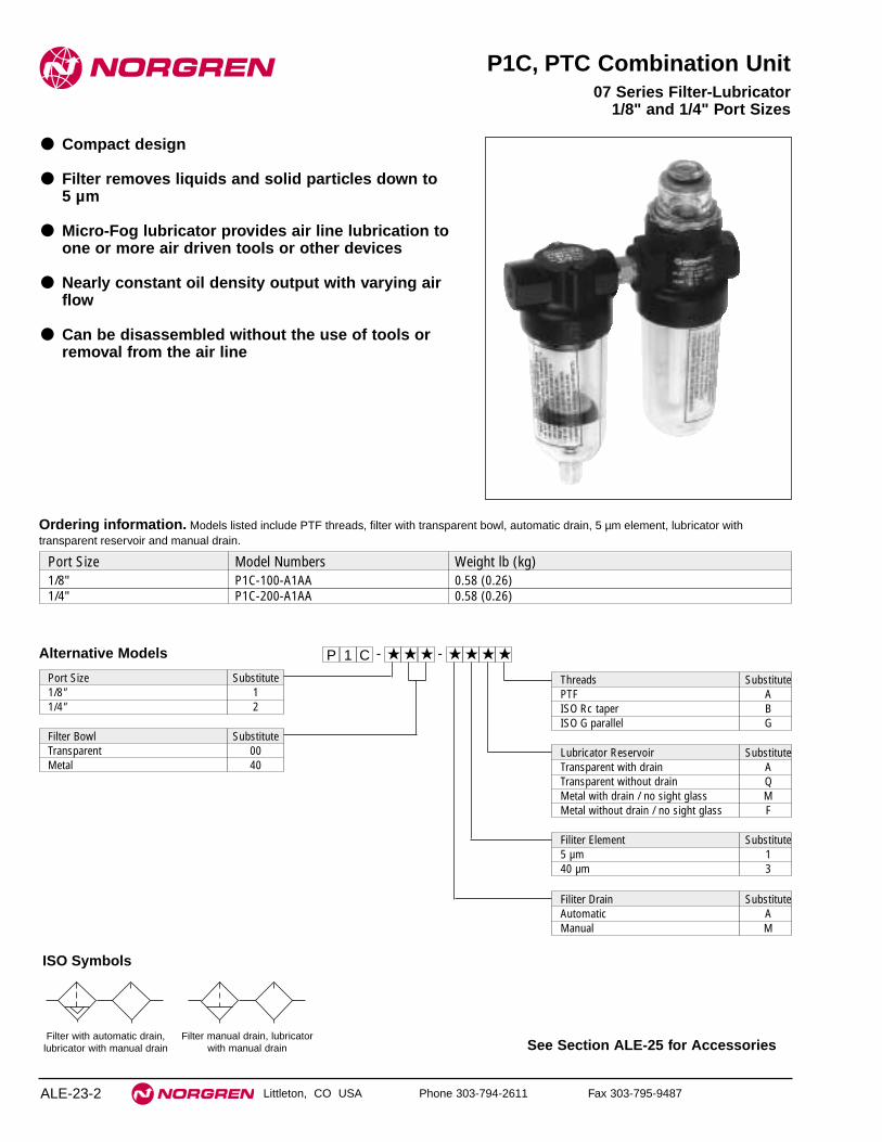
See Section ALE-25 for Accessories
Littleton, CO USA Phone 303-794-2611 Fax 303-795-9487
P1C, PTC Combination Unit
● Compact design
● Filter removes liquids and solid particles down to5 µm
● Micro-Fog lubricator provides air line lubrication toone or more air driven tools or other devices
● Nearly constant oil density output with varying airflow
● Can be disassembled without the use of tools orremoval from the air line
07 Series Filter-Lubricator1/8" and 1/4" Port Sizes
ALE-23-2
ISO Symbols
Filter with automatic drain,lubricator with manual drain
Filter manual drain, lubricatorwith manual drain
Alternative Models
Filter Bowl SubstituteTransparent 00Metal 40
Port Size Substitute1/8" 11/4" 2
Threads SubstitutePTF AISO Rc taper BISO G parallel G
Port Size Model Numbers Weight lb (kg)1/8" P1C-100-A1AA 0.58 (0.26)1/4" P1C-200-A1AA 0.58 (0.26)
Ordering information. Models listed include PTF threads, filter with transparent bowl, automatic drain, 5 µm element, lubricator withtransparent reservoir and manual drain.
Lubricator Reservoir SubstituteTransparent with drain ATransparent without drain QMetal with drain / no sight glass MMetal without drain / no sight glass F
Filiter Element Substitute5 µm 140 µm 3
Filiter Drain SubstituteAutomatic AManual M
P 1 C - ★ ★ ★ - ★ ★ ★ ★

F07-L07 Combination Unit
Littleton, CO USA Phone 303-794-2611 Fax 303-795-9487 ALE-23-3
All Dimensions in Inches (mm)
Technical DataFluid: Compressed airMaximum pressure:
Transparent bowl: 150 psig (10 bar)Metal bowl: 250 psig (17 bar)
Operating temperature *Transparent bowl: 0° to 125°F (-20° to 50°C)Metal bowl: 0° to 175°F (-20° to 80°C)
* Air supply must be dry enough to avoid ice formation at temperatures below 35°F (2°C).
Nominal bowl size: 1 fluid ounce (31 ml)Drain connection: Will fit 1/8-27 and 1/8-28 pipe threadFilterAutomatic drain operation: Spitter type drain operates momentarily when a rapid
change in air flow occurs or when the supply pressure is reduced.LubricatorStart point (i.e. minimum flow required for lubricator operation): 0.5 scfm (0.24
dm3/s) at 90 psig (6.3 bar) inlet pressureNominal bowl size: 1 fluid ounce (31 ml)Recommended lubricants: See Section ALE-29.Materials:
Body: ZincBowl
Transparent: PolycarbonateMetal: Zinc
Filter element: Sintered polypropyleneSight feed dome: Transparent nylonElastomers: Neoprene and nitrile
1.45
(37
)3.55 (90)
3.72
(94
) A
uto
mat
ic D
rain
3.87
(98
) M
anu
al D
rain
0.38
(10
)
0.38
(10
)
1.65
(42
)3.
07 (
78)
Wit
ho
ut
Dra
in
8.31
(21
1)**
** Minimum clearance to remove bowl
Item Type Part number
Service kits, filter 5 µm element 3652-1740 µm element 3852-18
Service kit, lubricator 3795-03
Replacement drains Manual 773-03Automatic 3654-02
Filter service kit contains element, element gasket, and bowl o-ring.Lubricator service kit contains sight-feed dome seal, cartridge o-ring, and bowl o-ring.
Service Kits

See Section ALE-25 for Accessories
Littleton, CO USA Phone 303-794-2611 Fax 303-795-9487
F72G, L72 Combination Units
● True modularity with Norgren Quikclamp™connections
● Quick release bayonet bowl
● Flow sensor design provides a nearly constant oil/airratio over a wide range of air flows
● Highly visible, prismatic liquid level indicator lens
● All around (360°) visibility of the sight-feed domesimplifies installation and adjustment
Use Micro-Fog models in applications containing one or morepoints of lubrication.Use Oil-Fog models to lubricate a single tool, cylinder, or other airdriven device.
Excelon 72 Filter-Lubricator1/4" and 3/8" Port Sizes
ALE-23-4
Technical DataFluid: Compressed airMaximum pressure:
Transparent bowl: 150 psig (10 bar)Metal bowl:
Manual or semi automatic drain: 250 psig (17 bar)Automatic drain: 150 psig (10 bar)
Operating temperature*:Transparent bowl: 0° to 125°F (-20° to 50°C)Metal bowl: 0° to 150°F (-20° to 65°C)
* Air supply must be dry enough to avoid ice formation at temperatures below 35°F (2°C).
Particle removal: 5 µm, 25 µm, or 40 µm filter elementManual drain connection: Will fit 1/8-27 and 1/8-28 pipe threadSemi automatic drain connection: Push on 5/16" (8 mm) ID tubeSemi automatic drain operating conditions (pressure operated)
Bowl pressure required to close drain: Greater than 1.5 psig (0.1 bar)Bowl pressure required to open drain: Less than 1.5 psig (0.1 bar) Minimum air flow required to close drain: 1 scfm (0.5 dm3/s)Manual operation: Lift stem to drain bowl
Automatic drain connection: Will fit 1/8-27 and 1/8-28 pipe threadAutomatic drain operating conditions (float operated)
Bowl pressure required to close drain: Greater than 5 psig (0.3 bar) Bowl pressure required to open drain: Less than 3 psig (0.2 bar)Minimum air flow required to close drain: 0.2 scfm (0.1 dm3/s)Manual operation: Depress pin inside drain outlet to drain bowl
Nominal bowl sizeShort bowl: 1.9 fluid ounce (56 ml)Long bowl: 2.2 fluid ounce (65 ml)
Recommended lubricants: See Section ALE-29.Materials
Body: ZincBowl
Transparent: PolycarbonateTransparent with guard: Polycarbonate, Zinc guardMetal: ZincMetal bowl liquid level indicator lens: Transparent nylon
Element: Sintered polypropyleneSight-Feed dome: Transparent nylonElastomers: Neoprene, nitrile
ISO Symbols
Filter with Automatic Drain Lubricator with Drain
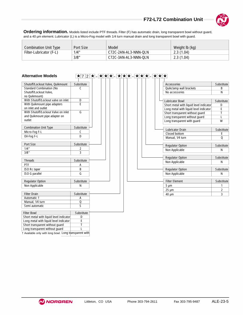
F72-L72 Combination Unit
Littleton, CO USA Phone 303-794-2611 Fax 303-795-9487 ALE-23-5
Ordering information. Models listed include PTF threads. Filter (F) has automatic drain, long transparent bowl without guard,and a 40 µm element. Lubricator (L) is a Micro-Fog model with 1/4 turn manual drain and long transparent bowl with guard.
Alternative Models
Threads SubstitutePTF AISO Rc taper BISO G parallel G
Filter Element Substitute5 µm 125 µm 240 µm 3
Combination Unit Type SubstituteMicro-Fog F-L COil-Fog F-L D
Port Size Substitute1/4" 23/8" 3
★ - ★★ ★7 2 -★★ ★ ★ - ★★ ★ - ★★ ★
Combination Unit Type Port Size Model Weight lb (kg)Filter-Lubricator (F-L) 1/4" C72C-2AN-AL3-NNN-QLN 2.3 (1.04)
3/8" C72C-3AN-AL3-NNN-QLN 2.3 (1.04)
Regulator Option SubstituteNon Applicable N
Regulator Option SubstituteNon Applicable N
Regulator Option SubstituteNon Applicable N
Regulator Option SubstituteNon Applicable N
Lubricator Drain SubstituteClosed bottom EManual, 1⁄4 turn Q
Accessories SubstituteQuikclamp wall brackets BNo accessories N
Filter Drain SubstituteAutomatic † AManual, 1⁄4 turn QSemi automatic S
Shutoff/Lockout Valve, Quikmount SubstituteStandard Combination (No CShutoff/Lockout Valve, no Quikmount)With Shutoff/Lockout valve on inlet DWith Quikmount pipe adapters Eon inlet and outletWith Shutoff/Lockout Valve on inlet Gand Quikmount pipe adapter on outlet
Lubricator Bowl SubstituteShort metal with liquid level indicator DLong metal with liquid level indicator EShort transparent without guard TLong transparent without guard LLong transparent with guard W
Filter Bowl SubstituteShort metal with liquid level indicator DLong metal with liquid level indicator EShort transparent without guard TLong transparent without guard L
Long transparent with† Available only with long bowl.

F72-L72 Combination Unit
Littleton, CO USA Phone 303-794-2611 Fax 303-795-9487ALE-23-6
All Dimensions in Inches (mm)
Standard Micro-Fog Type C72C-Standard Oil-Fog Type C72D-
Shown with optional Quikclamp wall bracket.
2.32
(59
) 1.
50(3
8)
4.22 (108)
2.11(54)
2.11(54)
Alternative Micro-Fog Type D72C- Alternative Oil-Fog Type D72D-
Includes Shutoff/Lockout valve.
Shown with optional Quikclamp wallbrackets.
2.11(54)
2.11(54)
2.32
(59
)
2.24 (56)
6.46 (164)
1.50
(38
)
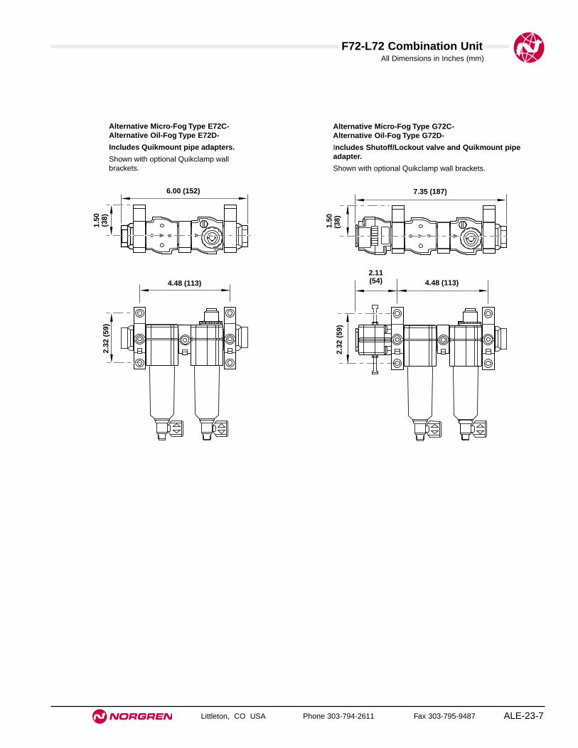
F72-L72 Combination Unit
Littleton, CO USA Phone 303-794-2611 Fax 303-795-9487 ALE-23-7
All Dimensions in Inches (mm)
Alternative Micro-Fog Type E72C- Alternative Oil-Fog Type E72D-
Includes Quikmount pipe adapters.
Shown with optional Quikclamp wallbrackets.
2.32
(59
)
4.48 (113)
6.00 (152)
1.50
(38
)
Alternative Micro-Fog Type G72C- Alternative Oil-Fog Type G72D-
Includes Shutoff/Lockout valve and Quikmount pipeadapter.
Shown with optional Quikclamp wall brackets.
2.32
(59
)
4.48 (113)2.11(54)
7.35 (187)
1.50
(38)

See Section ALE-25 for Accessories
Littleton, CO USA Phone 303-794-2611 Fax 303-795-9487
F73G, L73 Combination Units
● True modularity with Norgren Quikclamp™connections
● Quick release bayonet bowl
● Flow sensor design provides a nearly constant oil/airratio over a wide range of air flows
● Highly visible, prismatic liquid level indicator lens
● All around (360°) visibility of the sight-feed domesimplifies installation and adjustment
Use Micro-Fog models in applications containing one or morepoints of lubrication.Use Oil-Fog models to lubricate a single tool, cylinder, or other airdriven device.
Excelon 73 Filter-Lubricator1/4", 3/8", 1/2" Port Sizes
Technical DataFluid: Compressed airMaximum pressure
Transparent bowl: 150 psig (10 bar)Metal bowl: 250 psig (17 bar)
Operating temperature* Transparent bowl: 0° to 125°F (-20° to 50°C)Metal bowl: 0° to 175°F (-20° to 80°C)
* Air supply must be dry enough to avoid ice formation at temperatures below 35°F (2°C).Particle removal: 5 µm, 25 µm, or 40 µm filter elementManual drain connection: Will fit 1/8-27 and 1/8-28 pipe threadsAutomatic drain connection: Will fit 1/8-27 and 1/8-28 pipe threadsAutomatic drain operating conditions (float operated):
Bowl pressure required to close drain: Greater than 5 psig (0.3 bar)Bowl pressure required to open drain: Less than 3 psig (0.2 bar)Minimum air flow required to close drain: 0.2 scfm (0.1 dm3/s) Manual operation: Depress pin inside drain outlet to drain bowl
Nominal bowl size: 3.5 fluid ounce (0.1 liter)Recommended lubricants: See Section ALE-29.Materials
Body: AluminumBowl
Transparent: PolycarbonateTransparent with guard: Polycarbonate, steel guardMetal: AluminumMetal bowl liquid level indicator lens: Transparent nylon
Element: Sintered polypropyleneSight-Feed dome: Transparent nylonElastomers: Neoprene and nitrile
ALE-23-8
ISO Symbols
Filter with Automatic Drain Lubricator with Drain

F73-L73 Combination Unit
Littleton, CO USA Phone 303-794-2611 Fax 303-795-9487 ALE-23-9
Ordering informationModels listed in order table have PTF threads. Filter (F) has automatic drain, metal bowl with liquid level indicator, and a 40 µm element. Lubricator(L) is a Micro-Fog model with 1/4 turn manual drain and metal bowl with liquid level indicator.
Alternative Models
Threads SubstitutePTF AISO Rc taper BISO G parallel G
Filter Drain SubstituteAutomatic AManual, 1⁄4 turn Q
Accessories SubstituteAccessories B and D AQuikclamp wall brackets BAccessories B and Q CFilter service indicator DAccessories B, D, and Q HNo accessories NLubricator quick fill nipple Q
Filter Element Substitute5 µm 125 µm 240 µm 3
Combination Unit Type SubstituteMicro-Fog F-L COil-Fog F-L D
Port Size Substitute1/4" 23/8" 31/2" 4
★ - ★★ ★7 3 -★★ ★ ★ - ★★ ★ - ★★ ★
Lockout Valve/ Quikmount SubstituteStandard Combination (No CLockout Valve, no Quikmount)With Lockout valve on inlet DWith Quikmount pipe adapters Eon inlet and outletWith Lockout valve on inlet and GQuikmount pipe adapter onoutlet
Combination Unit Type Port Size Model Weight lb (kg)
Filter-Lubricator1/4" C73C-2AN-AD3-NNN-QDN 2.6 (1.18)
(F-L)3/8" C73C-3AN-AD3-NNN-QDN 2.6 (1.18)1/2" C73C-4AN-AD3-NNN-QDN 2.6 (1.18)
Regulator Option SubstituteNon Applicable N
Regulator Option SubstituteNon Applicable N
Regulator Option SubstituteNon Applicable N
Regulator Option SubstituteNon Applicable N
Lubricator Bowl SubstituteMetal with liquid level indicator DTransparent with guard PTransparent T
Lubricator Drain SubstituteClosed bottom EManual, 1⁄4 turn Q
Filter Bowl SubstituteMetal with liquid level indicator DTransparent with zinc guard PTransparent T

F73-L73 Combination Unit
Littleton, CO USA Phone 303-794-2611 Fax 303-795-9487ALE-23-10
All Dimensions in Inches (mm)
Standard Micro-Fog Type C73C-Standard Oil-Fog Type C73D-
Shown with optional Quikclamp wall bracket.
5.91 (150)
2.95(75)
2.95(75)
3.25
(83)
2.00
(51
)
Alternative Micro-Fog Type D73C- Alternative Oil-Fog Type D73D-
Includes lockout valve.
Shown with optional Quikclamp wall bracket.
8.58 (218)
2.40(61)
3.23(82)
2.95(75)
3.25
(83)
2.00
(51
)
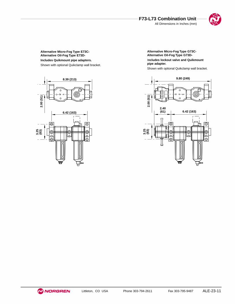
F73-L73 Combination Unit
Littleton, CO USA Phone 303-794-2611 Fax 303-795-9487 ALE-23-11
All Dimensions in Inches (mm)
Alternative Micro-Fog Type E73C- Alternative Oil-Fog Type E73D-
Includes Quikmount pipe adapters.
Shown with optional Quikclamp wall bracket.
8.39 (213)
6.42 (163)
3.25
(83)
2.00
(51
)
Alternative Micro-Fog Type G73C- Alternative Oil-Fog Type G73D-
Includes lockout valve and Quikmountpipe adapter.
Shown with optional Quikclamp wall bracket.
9.80 (249)
6.42 (163)2.40(61)
3.25
(83)
2.00
(51
)

See Section ALE-25 for Accessories
Littleton, CO USA Phone 303-794-2611 Fax 303-795-9487
F74G, L74 Combination Units
● True modularity with Norgren Quikclamp™connections
● Quick release bayonet bowl
● Flow sensor design provides a nearly constant oil/airratio over a wide range of air flows
● Highly visible, prismatic liquid level indicator lens
● All around (360°) visibility of the sight-feed domesimplifies installation and adjustment
Use Micro-Fog models in applications containing one or morepoints of lubrication.Use Oil-Fog models to lubricate a single tool, cylinder, or other airdriven device.
Excelon 74 Filter-Lubricator3/8", 1/2", 3/4" Port Sizes
Technical DataFluid: Compressed airMaximum pressure:
Transparent bowl: 150 psig (10 bar)Metal bowl: 250 psig (17 bar)
Operating temperature*:Transparent bowl: 0° to 125°F (-20° to 50°C)Metal bowl: 0° to 175°F (-20° to 80°C)
* Air supply must be dry enough to avoid ice formation at temperatures below 35°F (2°C).
Particle removal: 5 µm, 25 µm, or 40 µm filter elementManual drain connection: Will fit 1/8-27 and 1/8-28 pipe threadsAutomatic drain connection: Will fit 1/8-27 and 1/8-28 pipe threadsAutomatic drain operating conditions (float operated):
Bowl pressure required to close drain: Greater than 5 psig (0.3 bar)Bowl pressure required to open drain: Less than 3 psig (0.2 bar)Minimum air flow required to close drain: 2 scfm (1 dm3/s) Manual operation: Depress pin inside drain outlet to drain bowl
Nominal bowl size:Standard: 7 fluid ounce (0.2 liter)Optional size for lubricator: 1 quart US (1 liter)
Recommended lubricants: See Section ALE-29.Materials
Body: AluminumBowl
Transparent: Polycarbonate with steel bowl guardMetal: Aluminum
Metal bowl liquid level indicator lens7 fluid ounce (0.2 liter): Transparent nylon1 quart US (1 liter): Pyrex
Sight-Feed dome: Transparent nylonElastomers: Neoprene and NitrileElement: Sintered polypropyleneElastomers: Neoprene and Nitrile
ALE-23-12
ISO Symbols
Filter with Automatic Drain Lubricator with Drain
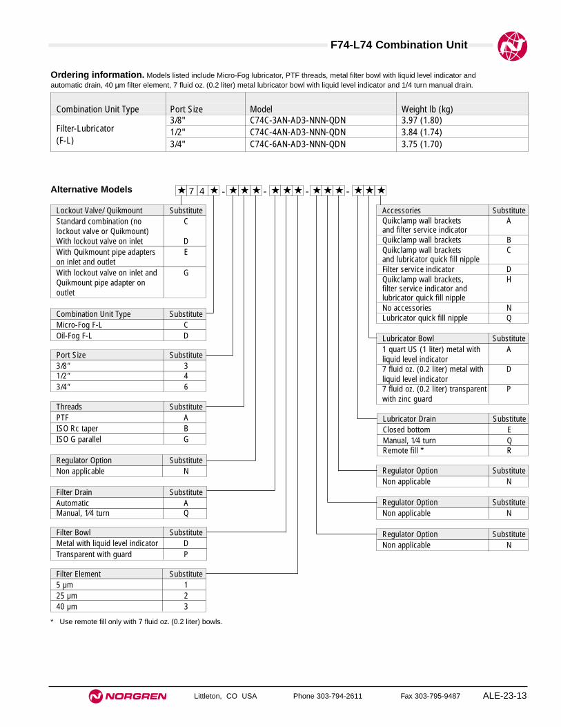
F74-L74 Combination Unit
Littleton, CO USA Phone 303-794-2611 Fax 303-795-9487 ALE-23-13
Ordering information. Models listed include Micro-Fog lubricator, PTF threads, metal filter bowl with liquid level indicator andautomatic drain, 40 µm filter element, 7 fluid oz. (0.2 liter) metal lubricator bowl with liquid level indicator and 1/4 turn manual drain.
Alternative Models
Threads SubstitutePTF AISO Rc taper BISO G parallel G
Filter Drain SubstituteAutomatic AManual, 1⁄4 turn Q
Accessories SubstituteQuikclamp wall brackets Aand filter service indicatorQuikclamp wall brackets BQuikclamp wall brackets Cand lubricator quick fill nippleFilter service indicator DQuikclamp wall brackets, Hfilter service indicator and lubricator quick fill nippleNo accessories NLubricator quick fill nipple Q
Filter Element Substitute5 µm 125 µm 240 µm 3
Combination Unit Type SubstituteMicro-Fog F-L COil-Fog F-L D
Port Size Substitute3/8" 31/2" 43/4" 6
★ - ★★ ★7 4 -★★ ★ ★ - ★★ ★ - ★★ ★
Lockout Valve/ Quikmount SubstituteStandard combination (no Clockout valve or Quikmount)With lockout valve on inlet DWith Quikmount pipe adapters Eon inlet and outletWith lockout valve on inlet and GQuikmount pipe adapter on outlet
Lubricator Bowl Substitute1 quart US (1 liter) metal with Aliquid level indicator7 fluid oz. (0.2 liter) metal with Dliquid level indicator7 fluid oz. (0.2 liter) transparent Pwith zinc guard
Filter Bowl SubstituteMetal with liquid level indicator DTransparent with guard P
Combination Unit Type Port Size Model Weight lb (kg)
Filter-Lubricator3/8" C74C-3AN-AD3-NNN-QDN 3.97 (1.80)
(F-L)1/2" C74C-4AN-AD3-NNN-QDN 3.84 (1.74)3/4" C74C-6AN-AD3-NNN-QDN 3.75 (1.70)
Lubricator Drain SubstituteClosed bottom EManual, 1⁄4 turn QRemote fill * R
* Use remote fill only with 7 fluid oz. (0.2 liter) bowls.
Regulator Option SubstituteNon applicable N
Regulator Option SubstituteNon applicable N
Regulator Option SubstituteNon applicable N
Regulator Option SubstituteNon applicable N

F74-L74 Combination Unit
Littleton, CO USA Phone 303-794-2611 Fax 303-795-9487ALE-23-14
All Dimensions in Inches (mm)
Standard Micro-Fog Type C74C- Standard Oil-Fog Type C74D-
Shown with optional Quikclamp wall bracket.
6.84 (174)
3.42(87)
3.42(87)
3.25
(83)
2.00
(51
)
Alternative Micro-Fog Type D74C- Alternative Oil-Fog Type D74D-
Includes Shutoff/Lockout valve.
Shown with optional Quikclamp wallbrackets.
10.13 (257)
3.03(77)
3.68(94)
3.42(87)
3.25
(83)
2.00
(51
)

F74-L74 Combination Unit
Littleton, CO USA Phone 303-794-2611 Fax 303-795-9487 ALE-23-15
All Dimensions in Inches (mm)
Alternative Micro-Fog Type E74C- Alternative Oil-Fog Type E74D-
Includes Quikmount pipe adapters.
Shown with optional Quikclamp wallbrackets.
9.32 (237)
7.37 (187)
3.25
(83)
2.00
(51
)Alternative Micro-Fog Type G74C- Alternative Oil-Fog Type G74D-
Includes Shutoff/Lockout valve and Quikmount pipeadapter.
Shown with optional Quikclamp wall brackets.
11.37 (289)
7.37 (187)3.03(77)
3.25
(83)
2.00
(51
)
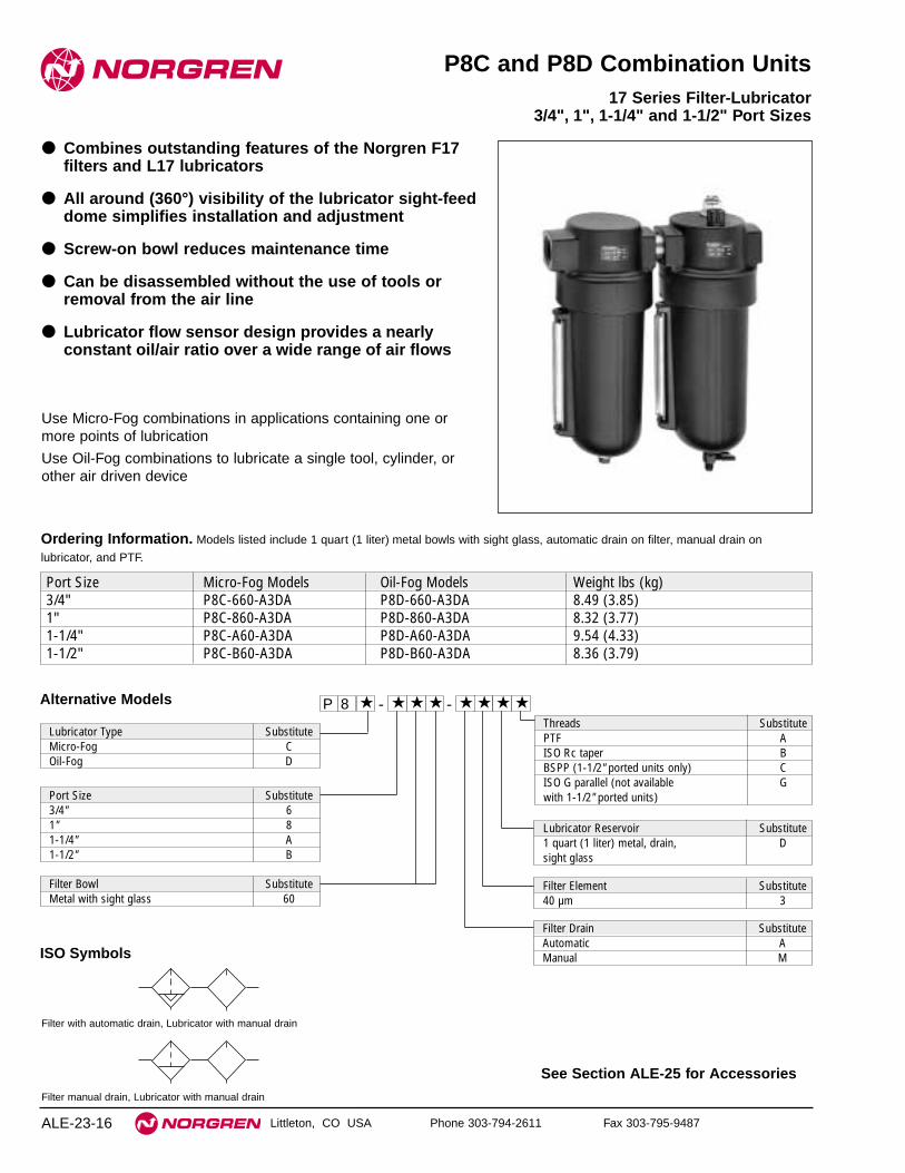
See Section ALE-25 for Accessories
Littleton, CO USA Phone 303-794-2611 Fax 303-795-9487
P8C and P8D Combination Units
● Combines outstanding features of the Norgren F17filters and L17 lubricators
● All around (360°) visibility of the lubricator sight-feeddome simplifies installation and adjustment
● Screw-on bowl reduces maintenance time
● Can be disassembled without the use of tools orremoval from the air line
● Lubricator flow sensor design provides a nearlyconstant oil/air ratio over a wide range of air flows
Use Micro-Fog combinations in applications containing one ormore points of lubrication
Use Oil-Fog combinations to lubricate a single tool, cylinder, orother air driven device
17 Series Filter-Lubricator3/4", 1", 1-1/4" and 1-1/2" Port Sizes
ALE-23-16
Alternative Models - ★★★ ★★ ★ -8 ★P ★
Threads SubstitutePTF AISO Rc taper BBSPP (1-1/2" ported units only) CISO G parallel (not available Gwith 1-1/2" ported units)
Lubricator Type SubstituteMicro-Fog COil-Fog D
Port Size Substitute3/4" 61" 81-1/4" A1-1/2" B
Filter Drain SubstituteAutomatic AManual M
Filter Bowl SubstituteMetal with sight glass 60
Ordering Information. Models listed include 1 quart (1 liter) metal bowls with sight glass, automatic drain on filter, manual drain on
lubricator, and PTF.
Port Size Micro-Fog Models Oil-Fog Models Weight lbs (kg)3/4" P8C-660-A3DA P8D-660-A3DA 8.49 (3.85)1" P8C-860-A3DA P8D-860-A3DA 8.32 (3.77)1-1/4" P8C-A60-A3DA P8D-A60-A3DA 9.54 (4.33)1-1/2" P8C-B60-A3DA P8D-B60-A3DA 8.36 (3.79)
Filter Element Substitute40 µm 3
Lubricator Reservoir Substitute1 quart (1 liter) metal, drain, Dsight glass
ISO Symbols
Filter with automatic drain, Lubricator with manual drain
Filter manual drain, Lubricator with manual drain

F17-L17 Combination Unit
Littleton, CO USA Phone 303-794-2611 Fax 303-795-9487 ALE-23-17
All Dimensions in Inches (mm)
Automatic Drain Manual Drain
16.9
(42
9)*
2.03
(52)
10.4
(26
5)
4.32
(11
0)10.25 (260)
1.25
(32
)10
.06
(256
)
2.40(61)
2.40(61)
* Minimum clearance required to remove bowl.
Item Type Part NumberLubricator service kit All o-rings, seals, gaskets 5771-02
Filter service kitAll o-rings, seals, gaskets 5578-0540 µm element 5311-03
Replacement drainAutomatic 3000-10Manual (1/4 Turn) 619-50
Sight glass kit All o-rings, seals, gaskets 2273-22
Sight glass kit contains bowl o-ring plus all o-rings, seals,screws, glass, and glass guard.
Service Kits
Technical DataFluid: Compressed airMaximum pressure: 250 psig (17 bar)Operating temperature*: 0° to 175°F (-20° to 80°C)* Air supply must be dry enough to avoid ice formation at temperatures below 2°C (35°F).Start point (minimum flow required for lubricator operation): 8 scfm (3.8 dm3/s) at
90 psig (6.3 bar) inlet pressureTypical flow with 90 psig (6.3 bar) inlet pressure and 7 psig
(0.5 bar) pressure drop:1" Ports: 250 scfm (118 dm3/s)
Nominal bowl size: 1 quart US (1 liter)Automatic drain connection: Will fit 1/8-27 and 1/8-28 pipe threadAutomatic drain operating conditions
Minimum pressure: 10 psig (0.7 bar).Drain opens when bowl pressure drops below 3 psig (0.2 bar).Minimum air flow: 2 scfm (1 dm3/s) required to close drain.
Recommended lubricants: See Section ALE-29.Materials
Body: AluminumBowls: AluminumBowl sight glass: PyrexSight-feed dome: Transparent nylonElastomers: Neoprene and nitrile
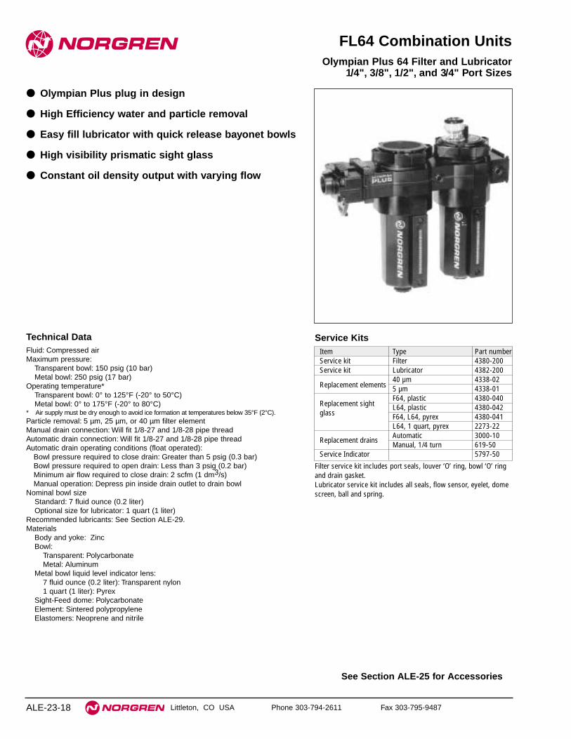
See Section ALE-25 for Accessories
ALE-23-18
Technical DataFluid: Compressed airMaximum pressure:
Transparent bowl: 150 psig (10 bar)Metal bowl: 250 psig (17 bar)
Operating temperature*Transparent bowl: 0° to 125°F (-20° to 50°C)Metal bowl: 0° to 175°F (-20° to 80°C)
* Air supply must be dry enough to avoid ice formation at temperatures below 35°F (2°C).Particle removal: 5 µm, 25 µm, or 40 µm filter elementManual drain connection: Will fit 1/8-27 and 1/8-28 pipe threadAutomatic drain connection: Will fit 1/8-27 and 1/8-28 pipe threadAutomatic drain operating conditions (float operated):
Bowl pressure required to close drain: Greater than 5 psig (0.3 bar)Bowl pressure required to open drain: Less than 3 psig (0.2 bar)Minimum air flow required to close drain: 2 scfm (1 dm3/s) Manual operation: Depress pin inside drain outlet to drain bowl
Nominal bowl sizeStandard: 7 fluid ounce (0.2 liter)Optional size for lubricator: 1 quart (1 liter)
Recommended lubricants: See Section ALE-29.Materials
Body and yoke: ZincBowl:
Transparent: PolycarbonateMetal: Aluminum
Metal bowl liquid level indicator lens:7 fluid ounce (0.2 liter): Transparent nylon1 quart (1 liter): Pyrex
Sight-Feed dome: PolycarbonateElement: Sintered polypropyleneElastomers: Neoprene and nitrile
Item Type Part numberService kit Filter 4380-200Service kit Lubricator 4382-200
Replacement elements40 µm 4338-025 µm 4338-01
Replacement sightF64, plastic 4380-040
glassL64, plastic 4380-042F64, L64, pyrex 4380-041L64, 1 quart, pyrex 2273-22
Replacement drainsAutomatic 3000-10Manual, 1/4 turn 619-50
Service Indicator 5797-50
Service Kits
Filter service kit includes port seals, louver ‘O’ ring, bowl ‘O’ ringand drain gasket.Lubricator service kit includes all seals, flow sensor, eyelet, domescreen, ball and spring.
Littleton, CO USA Phone 303-794-2611 Fax 303-795-9487
FL64 Combination Units
● Olympian Plus plug in design
● High Efficiency water and particle removal
● Easy fill lubricator with quick release bayonet bowls
● High visibility prismatic sight glass
● Constant oil density output with varying flow
Olympian Plus 64 Filter and Lubricator 1/4", 3/8", 1/2", and 3/4" Port Sizes

ALE-23-19
F64G, L64 Combination Unit
Littleton, CO USA Phone 303-794-2611 Fax 303-795-9487
Ordering information. Models listed include Micro-Fog lubricator, yoke with PTF threads, filter with auto drain, metal bowl with liquid level
indicator, 40 µm element; lubricator with 1/4 turn manual drain, 7 fluid ounce (0.2 liter) metal bowl with liquid level indicator.
Alternative Models
Threads SubstitutePTF AISO Rc taper BISO G parallel G
Filter Drain SubstituteAutomatic AManual, petcock DManual, 1⁄4 turn Q
Accessories SubstituteB and D AWall brackets BB and Q CFilter service indicator DB and L * FB, D, and Q HB, D, and L KLubricator low oil level switch * LNo accessories NLubricator quick fill cap Q
Regulator Option SubstituteNot Applicable N
Filter Element Substitute5 µm 125 µm 240 µm 375 µm 4
Combination Unit Type SubstituteStandard Micro-Fog F-L CStandard Oil-Fog F-L D
Port Size Substitute1/4" 23/8" 31/2" 43/4" 6
★ - ★★ ★6 4 -★★ ★ ★ - ★★ ★ - ★★ ★
Lockout Valve SubstituteNo lockout valve CWith lockout valve on inlet D
Lubricator Bowl Substitute1 quart (1 liter) metal with Apyrex liquid level indicator7 fluid oz. (0.2 liter) metal Dwith plastic liquid level indicator7 fluid oz. (0.2 liter) metal Mwithout liquid level indicator7 fluid oz. (0.2 liter) transparent Pwith guard7 fluid oz. (0.2 liter) metal with Rpyrex liquid level indicator
Filter Bowl SubstituteMetal with liquid level indicator DMetal, no liquid level indicator MTransparent with guard PMetal with pyrex liquid Rlevel indicator
Combination Unit Type Port Size Model Weight lb (kg)
Filter-Lubricator1/4" C64C-2AN-AD3-NNN-QDN 10.2 (4.61)
(F-L)3/8" C64C-3AN-AD3-NNN-QDN 9.7 (4.42)1/2" C64C-4AN-AD3-NNN-QDN 9.6 (4.35)3/4" C64C-6AN-AD3-NNN-QDN 8.8 (3.97)
Lubricator Drain SubstituteManual, petcock DClosed bottom EManual, 1⁄4 turn QRemote fill ** R
* Lubricator low oil level switch available only with 1 quart (1 liter) bowl.** Lubricator with remote fill available only with 7 fluid oz. (0.2 litre) bowls.
Regulator Option SubstituteNot Applicable N
Regulator Option SubstituteNot Applicable N
Regulator Option SubstituteNot Applicable N

64 Series Filter-Lubricator
Littleton, CO USA Phone 303-794-2611 Fax 303-795-9487ALE-23-20
All Dimensions in Inches (mm)
9.17 (233) [10.31 (262) with 3/4" ports]
1.44
(37
)
Man
ual
Dra
in 9
.21
(234
)A
uto
mat
ic D
rain
8.9
4 (2
27)
2.48
(63
)
2.91
(74
)8.
86**
(22
5)7.28 (185) [9.33 (237) with 3/4" ports]
** Minimum clearance required to remove bowl.

Littleton, CO USA Phone 303-794-2611 Fax 303-795-9487 ALE-24-1
Section 24
Excelon 72 Series Modular Components . . . . . . . . . . .ALE-24-2Excelon 73 Series Modular Components . . . . . . . . . . .ALE-24-3Excelon 73 Series Modular Components . . . . . . . . . . .ALE-24-4Olympus 64 Modular Components . . . . . . . . . . . . . . . .ALE-24-5
Modular ComponentsModular combination unitcomponents for Excelon 72, 73,and 74 Series, and OlympianPlus.
Quikclamp and WallMounting Bracket
Quikmount PipeAdaptors
Quikclamp
The Advantage of ModularityModular systems provide a time saving method ofconnecting and replacing air line components such asfilters, regulators, lubricators, and safety lockoutvalves.The heart of the Excelon system is the simple, one-piece Quikclamp that allows installation and removalof Excelon air preparation components andaccessories without breaking a pipe connection.All Excelon 72, 73, and 74 products are designed withintegral flanges that slide into V-grooves on theQuikclamp. Two face sealing o-rings provide a positiveseal when the clamp is closed and the captive screwis tightened.

72 Series Modular Components
Littleton, CO USA Phone 303-794-2611 Fax 303-795-9487ALE-24-2
All Dimensions in Inches (mm)
Quikclamp
Maximum Pressure: 17 bar (250 psig)Maximum Temperature: 65°C (150°F)
Use with all Excelon 72 Products toprovide modular installation capability.Flanges on the products slide into Vgrooves in the Quikclamp. Two face-sealing o-rings in the Quikclampprovide a positive seal when the clampis closed and the captive screw istightened. Tighten screw with a 3 mm hex wrenchor a T15 Torx wrench.
Quikclamp Service Kit (contains 2Nitrile o-rings): 4384-570A Quikclamp adds 0.26" (6.5 mm) tothe overall length of a combinationunit.
Part Number: 4214-51
QuikclampWall Mounting Bracket
Use with the Quikclamp to providesecure mounting to a wall, machinepanel or other flat surface.Use 3/16" (5 mm) screws to mountbracket to wall.
Part Number 4213-89
Quikclampand Wall Mounting Bracket
See Quikclamp paragraph fordescriptions and dimensions.Use 3/16" (5 mm) screws to mountbracket to wall.
Part Number 4214-52
Sub-base Mounted Pressure Switch
Monitors air pressure and provides anelectrical output when the pressuredrops below or exceeds an adjustablepreset pressure. Installs between twoQuikclamps. Also provides twoadditional 1/4" outlets for auxilliary air.P1max: 250 psig (17 bar)Temperature: 14° to 150°F
(-10° to 65°C)Adjustable 30 to 150 psig (2 to 10
bar). Shipped fromfactory preset at 90psig (6.3 bar)
Max. Voltage: 250 V a.c./d.c.Max. Current: 5 AmpHysteresis at Midpoint: 12%A Sub-base Mounted Pressure Switchadds 1.13" (29 mm) to the overalllength of a combination unit.
Auxiliary PortThreads Part Number1/4" PTF 4246-501/4" ISO Rc 4246-511/4" ISO G 4246-52
Porting Block
Installs between two Quikclamps toprovide three additional 1/4" outlets forauxiliary air.A Porting Block adds 1.13" (28.5 mm)to the overall length of a combinationunit.
Auxiliary PortSize & Thread Part Number
1/4" NPT 4216-501/4" ISO Rc 4216-511/4" IS0 G 4216-52
Replacement Pressure Switch
Use only with pressure switch sub-base. Cannot be used with the standardporting block.
Part Number: 4246-01
Quikmount Pipe Adaptors
Use with the Quikclamp to providethreaded connections to the systempiping.
A pipe adaptor adds 0.63" (16 mm) tothe overall length of a combinationunit.
Port Size Part No.and Thread (Quantity of 1)
1/4" PTF 4215-023/8" PTF 4215-03
1/4" ISO Rc 4215-053/8" ISO Rc 4215-061/4" ISO G 4215-083/8" ISO G 4215-09
Manifold Block
Installs with Quikclamps. Ports arethreaded 3/8" pipe to providemanifolding capability for up to threecomponents.
SidePort Threads Part Number
3/8" PTF 4228-013/8" ISO Rc 4228-023/8" ISO G 4228-03
0.59(15)
2.91
(74
)
2.32
(59
) Port CL
Wall
1.50 (38)
1.98(50)
1.76(45)
Transition Connector
Enables connection of Excelon 72 to 74units. Typically this will allow F74C/Hhigh grade coalescing filters to be flowmatched with R72 regulators.
Part Number: 4417-01
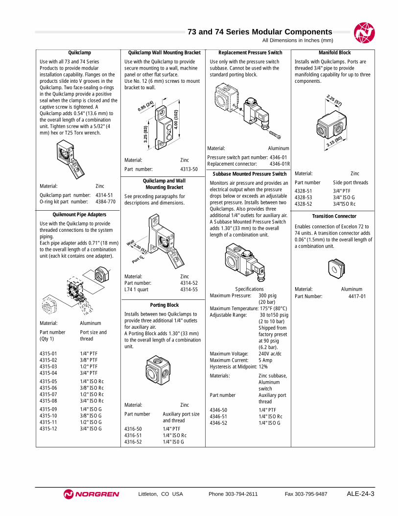
73 and 74 Series Modular Components
Littleton, CO USA Phone 303-794-2611 Fax 303-795-9487 ALE-24-3
All Dimensions in Inches (mm)
Quikclamp
Use with all 73 and 74 SeriesProducts to provide modularinstallation capability. Flanges on theproducts slide into V grooves in theQuikclamp. Two face-sealing o-ringsin the Quikclamp provide a positiveseal when the clamp is closed and thecaptive screw is tightened. AQuikclamp adds 0.54" (13.6 mm) tothe overall length of a combinationunit. Tighten screw with a 5/32" (4mm) hex or T25 Torx wrench.
Material: Zinc
Quikclamp part number: 4314-51O-ring kit part number: 4384-770
Manifold Block
Installs with Quikclamps. Ports arethreaded 3/4" pipe to providemanifolding capability for up to threecomponents.
Material: Zinc
Part number Side port threads
4328-51 3/4" PTF4328-53 3/4" ISO G4328-52 3/4"ISO Rc
Transition Connector
Enables connection of Excelon 72 to74 units. A transition connector adds0.06" (1.5mm) to the overall length ofa combination unit.
Material: AluminumPart Number: 4417-01
Replacement Pressure Switch
Use only with the pressure switchsubbase. Cannot be used with thestandard porting block.
Material: Aluminum
Pressure switch part number: 4346-01Replacement connector: 4346-01R
Subbase Mounted Pressure Switch
Monitors air pressure and provides anelectrical output when the pressuredrops below or exceeds an adjustablepreset pressure. Installs between twoQuikclamps. Also provides threeadditional 1/4" outlets for auxiliary air.A Subbase Mounted Pressure Switchadds 1.30" (33 mm) to the overall length of a combination unit.
SpecificationsMaximum Pressure: 300 psig
(20 bar)Maximum Temperature: 175°F (80°C)Adjustable Range: 30 to150 psig
(2 to 10 bar) Shipped from factory preset at 90 psig (6.2 bar).
Maximum Voltage: 240V ac/dcMaximum Current: 5 AmpHysteresis at Midpoint: 12%
Materials: Zinc subbase,Aluminumswitch
Part number Auxiliary port thread
4346-50 1/4" PTF4346-51 1/4" ISO Rc4346-52 1/4" ISO G
Porting Block
Installs between two Quikclamps toprovide three additional 1/4" outletsfor auxiliary air.A Porting Block adds 1.30" (33 mm)to the overall length of a combinationunit.
Material: Zinc
Part number Auxiliary port sizeand thread
4316-50 1/4" PTF4316-51 1/4" ISO Rc4316-52 1/4" IS0 G
Quikclamp and Wall Mounting Bracket
See preceding paragraphs fordescriptions and dimensions.
Material: ZincPart number: 4314-52L74 1 quart 4314-55
Quikclamp Wall Mounting Bracket
Use with the Quikclamp to providesecure mounting to a wall, machinepanel or other flat surface.Use No. 12 (6 mm) screws to mountbracket to wall.
Material: Zinc
Part number: 4313-50
Quikmount Pipe Adapters
Use with the Quikclamp to providethreaded connections to the systempiping.Each pipe adapter adds 0.71" (18 mm)to the overall length of a combinationunit (each kit contains one adapter).
Material: Aluminum
Part number Port size and (Qty 1) thread
4315-01 1/4" PTF4315-02 3/8" PTF4315-03 1/2" PTF4315-04 3/4" PTF
4315-05 1/4" ISO Rc4315-06 3/8" ISO Rc4315-07 1/2" ISO Rc4315-08 3/4" ISO Rc
4315-09 1/4" ISO G4315-10 3/8" ISO G4315-11 1/2" ISO G4315-12 3/4" ISO G
3.25
(83
) 4.00
(10
2) 0.95 (24)
Port CL
2.00 (51)
Wall
2.25 (57)
3.15 (80)
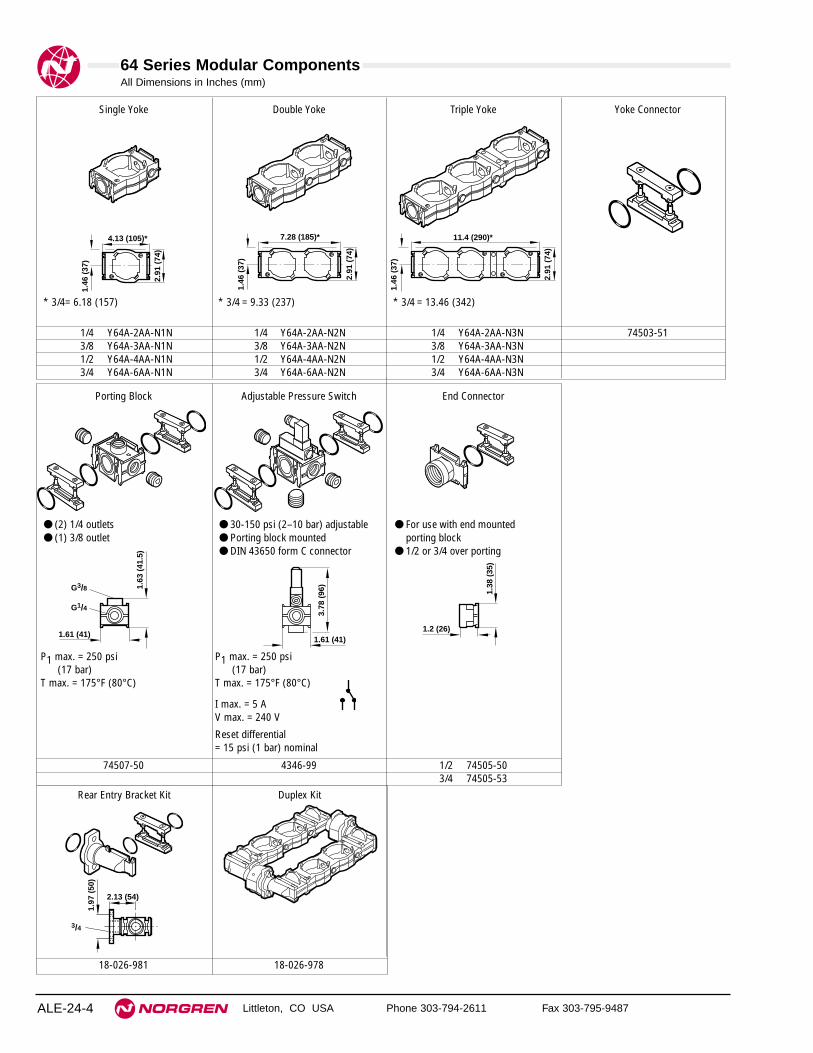
64 Series Modular Components
Littleton, CO USA Phone 303-794-2611 Fax 303-795-9487ALE-24-4
All Dimensions in Inches (mm)
Rear Entry Bracket Kit Duplex Kit
18-026-981 18-026-978
Single Yoke Double Yoke Triple Yoke Yoke Connector
1/4 Y64A-2AA-N1N 1/4 Y64A-2AA-N2N 1/4 Y64A-2AA-N3N 74503-513/8 Y64A-3AA-N1N 3/8 Y64A-3AA-N2N 3/8 Y64A-3AA-N3N1/2 Y64A-4AA-N1N 1/2 Y64A-4AA-N2N 1/2 Y64A-4AA-N3N3/4 Y64A-6AA-N1N 3/4 Y64A-6AA-N2N 3/4 Y64A-6AA-N3N
11.4 (290)*
1.46
(37
)
2.91
(74
)
4.13 (105)*
1.46
(37
)
2.91
(74
)
7.28 (185)*1.
46 (
37)
2.91
(74
)
Porting Block Adjustable Pressure Switch End Connector
74507-50 4346-99 1/2 74505-503/4 74505-53
1.63
(41
.5)
1.61 (41)
G3/8
G1/4
1.38
(35
)
1.2 (26)
1.97
(50
)
2.13 (54)
3/4
● (2) 1/4 outlets● (1) 3/8 outlet
● 30-150 psi (2–10 bar) adjustable● Porting block mounted ● DIN 43650 form C connector
● For use with end mountedporting block
● 1/2 or 3/4 over porting
* 3/4= 6.18 (157)
P1 max. = 250 psi(17 bar)
T max. = 175°F (80°C)
P1 max. = 250 psi(17 bar)
T max. = 175°F (80°C)
I max. = 5 AV max. = 240 V
Reset differential = 15 psi (1 bar) nominal
* 3/4 = 9.33 (237) * 3/4 = 13.46 (342)
1.61 (41)
3.78
(96
)

Littleton, CO USA Phone 303-794-2611 Fax 303-795-9487 ALE-25-1
Section 25
ContentsFilters . . . . . . . . . . . . . . . . . . . . . . . . . . . . . . . . . . . . . . .ALE-25-2 Regulators . . . . . . . . . . . . . . . . . . . . . . . . . . . . . . . . . . .ALE-25-4 Filter/Regulators . . . . . . . . . . . . . . . . . . . . . . . . . . . . .ALE-25-12Lubricators . . . . . . . . . . . . . . . . . . . . . . . . . . . . . . . . . .ALE-25-15Relief Valves . . . . . . . . . . . . . . . . . . . . . . . . . . . . . . . . .ALE-25-19Shut-Off Valves . . . . . . . . . . . . . . . . . . . . . . . . . . . . . .ALE-25-21Smooth Start & Directional Control Valves . . . . . . . . .ALE-25-22
Accessories for Filters,Regulators, and Lubricators

Filter Accessories
Littleton, CO USA Phone 303-794-2611 Fax 303-795-9487ALE-25-2
All Dimensions in Inches (mm)
1.02
(26)
0.22
(6)
1.33
(34
)
1.50 (38)
0.93(24)
0.29 (7)
1.34
(34
)
2.06
(52
)
1.59
(40
)
F07, F39 Bracket (5939-06)
1.00(25)
3.1
9 (8
1)
5.13
(13
0)
1.69
(43)
3.00
(76
)
Port C L
0.34 (9) Dia.
F17, F46 Bracket (6212-50,6212-51)
0.33
(8.
5)2.
05 (
52)
3.54
(90
)1.
22 (
31)
4.06 (103)
4.80 (122)
F22 Bracket (18-001-962)
5.63 (143)
4.49 (114)
0.32
(8.
2)3.
35 (
85)
0.43 (11) 0.57 (14.5)
3.66
(93
)
1.20
(30
.5)
1.89
(48
)
4.33
(11
0)
F64 Bracket (74504-50)
Product Accessory Part No.F07 Wall bracket 5939-06
F17 Wall bracket 3/4", 1" Ports: 6212-501-1/4", 1-1/2" Ports: 6212-51
F22 Wall bracket 18-001-962
F39 Wall bracket 5939-06
F46 Wall bracket 3/4", 1" Ports: 6212-501-1/4", 1-1/2" Ports: 6212-51
F64 Wall bracket 74504-50

Filter Accessories
Littleton, CO USA Phone 303-794-2611 Fax 303-795-9487 ALE-25-3
Product Accessory Part No.F68 Wall bracket 1/2", 3/4", 1", 1-1/4" Ports: 18-001-978
1-1/2" Ports: Not Available
F72 Wall bracket 4224-50
F73 Wall Bracket 4424-50
Electric service indicator 4020-51RProvides electrical signal whenelement needs to be replaced.
Visual service indicator 5797-50Turns from green to red whenelement needs to be replaced.
F74 Wall bracket 4324-50
Electric service indicator 4020-51RProvides electrical signal whenelement needs to be replaced.
Visual service indicator 5797-50Turns from green to red whenelement needs to be replaced.
0.24
(6)
0.20 (5)0.47(12)
Port CL
1.77 (45)
1.50
(38
)
2.36
(60
)
Port CL
1.54
(39
)
2.00
(51
)0.79(20)
0.71 (18)
0.16 (4)
F72 Bracket (4224-50)
2.88 (73)
2.00
(51
)
3.25
(83
)
Port CL
0.20
(5)
0.77
(20)
0.24
(6)
1.97
(50
)
2.40
(61
)
0.16(4)
1.46(37)
1.00(25)
Port CL
F74 Bracket (4324-50)
1.10(28) 0.71
(18)0.16 (4)
0.24
(6)
0.28
(7)
0.74
(19)
2.40
(61)
1.89
(48)
2.37 (60)
2.64
(67)
1.50
(38)
Port CL
Port CL
F73 Bracket (4424-50)
All Dimensions in Inches (mm)
8.19 (208)*
7.48 (190)*
3.94
(10
0)
1.97
(50)
2.84
(72
)
0.33
(8.
5)
0.59 (15)
7.48190 (190)
* Add 0.39" (10) for 1-1/4" ported yokes.
F68 Bracket (18-001-978)

Regulator Accessories
Littleton, CO USA Phone 303-794-2611 Fax 303-795-9487ALE-25-4
Product Accessory Part No.R05 Plastic panel nut 2962-89
R06 Wall bracket for R06 Bracket and plastic nut: 18-025-003with plastic bonnet Plastic nut: 2962-89
Metal nut: 2962-04
Wall bracket for R06 Bracket and metal nut: 18-001-021with brass bonnet Metal nut: 616-01
Tamper resistant knob 18-001-092
R07 Wall bracket with Bracket and plastic nut: 18-025-003plastic nut Plastic nut: 2962-89
Metal nut: 2962-04
Tamper resistant knob 18-001-092
R17 Wall bracket with Bracket and plastic nut: 5570-04plastic nut Plastic nut: 5226-89
Metal nut: 5226-97
Tamper resistant 2117-01seal wire
R18 Muffler 3/4 PTF: MB006AR 3/4: MB006B
All Dimensions in Inches (mm)
0.38
(10)
0.69
(18)
0.22
(6)
1.50 (38)
0.29 (7)
0.93(24)
2.47
(63
)
1.63
(41
)
0.63
(16)
R06, R07 Bracket (18-025-003)
0.38
(10
)
0.69
(18)
0.22
(6)
1.38 (35)
0.35 (9)
0.69(18)
2.41
(61
)
1.63
(41
)
0.63
(16
)
1.0
(25)
R06 Bracket for Brass Bonnet (18-001-021)
4.50
(11
4)
3.19
(81
)
PipeCL
0.28
(7)
1.19
(30
)0.
56 (
14)
1.08 (27)
3.50 (89)
0.54(14)
R17 Bracket (5570-04)

Regulator Accessories
Littleton, CO USA Phone 303-794-2611 Fax 303-795-9487 ALE-25-5
Product Accessory Part No.
R22 Wall bracket 18-001-962
Wall bracket Bracket and metal nut: 18-001-959(neck mount) Metal nut: 5988-02
R24 Wall bracket with Bracket and metal nut: 18-999-412metal nut Plastic nut: 2962-89
Metal nut: 2962-04
Reducing bushing 3/8 to 1/4 PTF: 5950-01for gauge ports 1/2 to 1/4 PTF: 2339-04
R1/4 to G1/8: 150232818R3/8 to G1/8: 150233818R1/2 to G1/8: 150234818
R30M Plastic panel nut 2962-89Metal panel nut 2962-04
Tamper resistant knob 18-001-092
Push-in connector 8 mm: 11-002-080010 mm: 11-002-1000
Push-in plug 8 mm: 11-004-080010 mm: 11-004-1000
Push-in gauge adapter 8 mm: 74679-0210 mm: 74679-03
All Dimensions in Inches (mm)
0.33
(8.
5)
1.22
(31
)
2.05
(52
)
3.18
(81
)
3.39 (86)
4.17 (106)
R22 Bracket (18-001-962)
0.98
(25
)
2.00
(50
)
3.11
(79
)
2.13 (54)
2.95 (75)
0.33
(8.
5)
R22 Neck Bracket (18-001-959)
1.73
(44
)
3.05
(77
.5)
1.8 (46)
1.26 (32)
3.23
(82
)
2.91
(74
)0.
2 (5
)
1.73
(44
)
3.05
(77
.5)
1.8 (46)
1.26 (32)
2.95
(75
)
2.64
(67
)0.
2 (5
)
1/4", 3/8", 1/2" Ports 3/4", 1", 1-1/4" Ports
R24 Bracket (18-999-412)
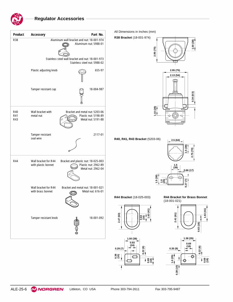
Regulator Accessories
Littleton, CO USA Phone 303-794-2611 Fax 303-795-9487ALE-25-6
Product Accessory Part No.R38 Aluminum wall bracket and nut: 18-001-974
Aluminum nut: 5988-01
Stainless steel wall bracket and nut: 18-001-973Stainless steel nut: 5988-02
Plastic adjusting knob 655-97
Tamper resistant cap 18-004-987
R40 Wall bracket with Bracket and metal nut: 5203-06R41 metal nut Plastic nut: 5198-89R43 Metal nut: 5191-88
Tamper resistant 2117-01seal wire
R44 Wall bracket for R44 Bracket and plastic nut: 18-025-003with plastic bonnet Plastic nut: 2962-89
Metal nut: 2962-04
Wall bracket for R44 Bracket and metal nut: 18-001-021with brass bonnet Metal nut: 616-01
Tamper resistant knob 18-001-092
All Dimensions in Inches (mm)
0.38
(10)
0.69
(18)
0.22
(6)
1.50 (38)
0.29 (7)
0.93(24)
2.47
(63
)
1.63
(41
)
0.63
(16)
R44 Bracket (18-025-003)
0.38
(10
)
0.69
(18)
0.22
(6)
1.38 (35)
0.35 (9)
0.69(18)
2.41
(61
)
1.63
(41
)
0.63
(16
)
1.0
(25)
R44 Bracket for Brass Bonnet (18-001-021)
2.95 (75)
2.13 (54)
2.95
(75
)1.
10 (
28)
1.50
(38
)0.
34 (
8.5)
R38 Bracket (18-001-974)
2.75
(70
)
1.5
(38)
2.5 (64)
1.5
(38)
1.0
(25)
1.5(38)
0.66 (17)
0.27
(7)
R40, R41, R43 Bracket (5203-06)

Regulator Accessories
Littleton, CO USA Phone 303-794-2611 Fax 303-795-9487 ALE-25-7
Product Accessory Part No.R64 Wall bracket 74504-50
Metal panel nut 4348-89
Tamper resistant cover and wire. Cover and wire: 4355-51Install over knob to help prevent Wire: 2117-01tampering of pressure setting.Use up to 4 padlocks with 5/16"(8mm) diameter shackle to secure cover. Lockout hasp may also be used.
Lockout hasp. 54547-01Allows use of up to 6 padlocks with5/16" (8mm) diameter shackle.
R68 Wall bracket 1/2", 3/4", 1", 1-1/4" Ports: 18-001-9781-1/2" Ports: Not Available
Tamper resistant cover and wire. Cover and wire: 4355-51Install over knob to help prevent Wire: 2117-01tampering of pressure setting.Use up to 4 padlocks with 5/16"(8mm) diameter shackle to secure cover. Lockout hasp may also be used.
Lockout hasp. 54547-01Allows use of up to 6 padlocks with5/16" (8mm) diameter shackle.
R72 Wall bracket 4224-50
Wall bracket/plastic nut Bracket and plastic nut: 74316-50Plastic nut: 4248-89Metal Nut: 4248-01
Tamper resistant cover and wire. Cover and wire: 4255-51Install over knob to help prevent Wire: 2117-01tampering of pressure setting.Use up to 2 padlocks with 5/16"(8mm) diameter shackle to secure cover. Lockout hasp may also be used.
Lockout hasp. 54547-01Allows use of up to 6 padlocks with5/16" (8mm) diameter shackle.
All Dimensions in Inches (mm)
0.24
(6)
0.20 (5)0.47(12)
Port CL
1.77 (45)
1.50
(38
)
2.36
(60
)
Port CL
1.54
(39
)
2.00
(51
)
0.79(20)
0.71 (18)
0.16 (4)
R72 Bracket (4224-50)1.
1 (2
8)
1.5
(38)
1.9 (49)
1.0
(25)
1.0
(25)
1.2(30)
0.3 (8)
0.2
(4)
R72 Neck Bracket (74316-50)
5.63 (143)
4.49 (114)
0.32
(8.
2)3.
35 (
85)
0.43 (11) 0.57 (14.5)
3.66
(93
)
1.20
(30
.5)
1.89
(48
)
4.33
(11
0)
R64 Bracket (74504-50)
8.19 (208)*
7.48 (190)*
3.94
(10
0)
1.97
(50)
2.84
(72
)
0.33
(8.
5)
0.59 (15)
7.48190 (190)
* Add 0.39" (10) for 1-1/4" ported yokes.
R68 Bracket (18-001-978)

Regulator Accessories
Littleton, CO USA Phone 303-794-2611 Fax 303-795-9487ALE-25-8
All Dimensions in Inches (mm)
1.10(28) 0.71
(18)0.16 (4)
0.24
(6)
0.28
(7)
.74
(19)
2.40
(61)
1.89
(48)
2.37 (60)
2.64
(67)
1.50
(38)
Port CL
Port CL
R73 Bracket (4424-50)
1.5
(38)
2.5 (64)
2.75
(70
)
1.5
(38)
1.0
(25)
1.5(38)
0.66 (17)
0.27
(7)
R73 Neck Bracket (4461-50)
2.88 (73)
2.00
(51
)
3.25
(83
)
Port CL
0.20
(5)
0.77
(20)
0.24
(6)
1.97
(50
)
2.40
(61
)
0.16(4)
1.46(37)
1.00(25)
Port CL
R74 Bracket (4324-50)
3.37
(86)
2.06
(52)
0.9
(23)
2.2 (56)
3.5 (89)
0.95(24)
0.28
(7)
R74 Neck Bracket (4368-51)
Product Accessory Part No.R73 Wall bracket 4424-50
Wall bracket/metal nut Bracket and metal nut: 4461-50Metal Nut: 5191-88
Plastic Nut: 5191-89
Tamper resistant cover and wire. Cover and wire: 4455-51Install over knob to help prevent Wire: 2117-01tampering of pressure setting.Use up to 4 padlocks with 5/16"(8mm) diameter shackle to secure cover. Lockout hasp may also be used.
Lockout hasp. 54547-01Allows use of up to 6 padlocks with5/16" (8mm) diameter shackle.
R74 Wall bracket 4324-50
Wall bracket/metal nut Bracket and metal nut: 4368-51Metal Nut: 4348-89
Tamper resistant cover and wire. Cover and wire: 4355-51Install over knob to help prevent Wire: 2117-01tampering of pressure setting.Use up to 4 padlocks with 5/16"(8mm) diameter shackle to secure cover. Lockout hasp may also be used.
Lockout hasp. 54547-01Allows use of up to 6 padlocks with5/16" (8mm) diameter shackle.

Regulator Accessories
Littleton, CO USA Phone 303-794-2611 Fax 303-795-9487 ALE-25-9
Product Accessory Part No.R81 Wall bracket 5095-51R82R83R84
Pipe plug, hex socket 1/4 PTF: 2891-97
Nipple 1/4 PTF male: 18-006-067
Union adapter with cap1/4 PTF to 1/4 tube (45° flare): 18-006-068
Adapter only: 18-006-027Cap only: 3302-50
Cylinder connector, nitrogen service, 0.906-14 RH external thread
CGA No. 580: 18-008-004
Cylinder connector, carbon dioxide service, 0.830-14 RH internal thread
CGA No 320: 18-008-002With 2.25" (57mm) long nipple: 18-008-015
Replacement gasket: 1390-02
Check valves *1/4 PTF male to 1/4 tube (45° flare): 16-009-001
1/4 PTF male to 1/2-16 BSF: 16-009-0021/4 PTF male to 1/4 PTF female: 16-009-003
Check and relief valve **Relief cracking pressure: 130±4 psig (9 ±0.28 bar)
1/4 PTF male to 1/4 tube (45° flare): 16-006-107
Manifolds with integral check valve *
2 or 3 outlets, 1/4 PTF male to 1/4 tube (45° flare): 3228-542 or 3 outlets, 1/4 PTF male to 1/2-16 BSF: 3228-55
4 or 5 outlets, 1/4 PTF male to 1/4 tube (45° flare): 3228-604 or 5 outlets, 1/4 PTF male to 1/2-16 BSF: 3228-61
Manifold extension1/4 PTF male to 1/4 PTF female: 2340-50
Streamline wye †1/4 PTF male to 1/4 PTF female: 18-006-016
All Dimensions in Inches (mm)
0.28
(7)
Typ
2.75
(70
)0.
31 (
8)T
yp
2 (51)1.03 (26)
0.31 (8)
0.5 (13)
R81, R82, R83, R84 Bracket (5095-51)
* The listed check valves and manifolds with integral check valves are designed for use with Norgren beverage regulators (R81, R82, R84) tohelp prevent the back flow of liquids into the regulator.
** The 16-006-107 check and relief valve meets the pressure and flow requirements of paragraphs 4.5 and 4.6 of NSDA Pamphlet TD02,Installation and Operational Procedures for Pressurized Soft Drink Dispensing Systems, dated July, 1980.
† Check valves, or manifolds with integral check valves, must be installed in the outlet ports of the wye when the wye is installed in the outlet portof Norgren beverage regulators.

Regulator Accessories
Littleton, CO USA Phone 303-794-2611 Fax 303-795-9487ALE-25-10
Product Accessory Part No.R91 Wall bracket with Bracket and plastic nut: 18-025-003
plastic nut Plastic nut: 2962-89Metal nut: 2962-04
Tamper resistant knob 18-001-092
11-002 Wall bracket 18-001-003
Panel mount kit with T-bar adjustment 18-003-004
Panel mount kit with 18-003-002hand wheel adjustment
Panel mount kit with screw adjustment 18-003-006
11-008 Wall bracket Units with 1/2" ports: 18-001-003Units with 3/4" and 1" ports: 18-001-027
All Dimensions in Inches (mm)
0.38
(10)
0.69
(18)
0.22
(6)
1.50 (38)
0.29 (7)
0.93(24)
2.47
(63
)
1.63
(41
)
0.63
(16)
R91 Bracket (18-025-003)
3.25 (83)
2.25
(57
)
2.44
(62
)
1.88(48)
0.63 (16)
1.25
(32
)
0.44
(11
)
8 (7
)
11-002 Bracket11-008 Bracket (Units with 1/2" Ports)(18-001-003)
4.88 (124)
0.32
(8)
2.94
(75
)
5.38
(13
7)3.
31 (
84)
3.27 (83)
11-008 Bracket (Units with 3/4" and 1" Ports) (18-001-027)

Regulator Accessories
Littleton, CO USA Phone 303-794-2611 Fax 303-795-9487 ALE-25-11
0.38
(10)
0.69
(18)
0.22
(6)
1.50 (38)
0.29 (7)
0.93(24)
2.47
(63
)
1.63
(41
)
0.63
(16)
11-044 Bracket (18-025-003)
Product Accessory Part No.11-009 Wall bracket 18-001-029
Screw adjustment 1095-02
11-018 Tamper resistant cap 639-02
11-042 Muffler 3/4 PTF: MB006AR3/4: MB006B
11-044 Wall bracket with Bracket and plastic nut: 18-025-003plastic nut Plastic nut: 2962-89
Metal nut: 2962-04
Tamper resistant knob 18-001-092
11400- Wall bracket 18-001-00320AL
All Dimensions in Inches (mm)
4.88 (124)
2.94
(75
)
3.19
(81
)
3.25(83)
0.63 (16)
2.00
(51
)
0.50
(13
)
0.31
(8)
3.19
(81)
Port CL
Port CL
11-009 Bracket (18-001-029)
3.25 (83)
2.25
(57
)
2.44
(62
)1.88(48)
0.63 (16)
1.25
(32
)
0.44
(11
)
0.28
(7)
11400- Bracket 20AL Bracket (18-001-003)

Filter/Regulator Accessories
Littleton, CO USA Phone 303-794-2611 Fax 303-795-9487ALE-25-12
Product Accessory Part No.B05 Plastic Panel Nut 2962-89
B07 Wall bracket with Bracket and plastic nut: 18-025-003plastic nut Plastic nut: 2962-89
Metal nut: 2962-04
Tamper resistant knob 18-001-092
B38 Aluminum wall bracket and nut: 18-001-974Aluminum nut: 5988-01
Stainless steel wall bracket and nut: 18-001-973Stainless steel nut: 5988-02
Plastic adjusting knob 655-97
Tamper resistant cap 18-004-987
B39 Wall bracket with Bracket and plastic nut: 18-025-003plastic nut Plastic nut: 2962-89
Metal nut: 2962-04
Tamper resistant knob 18-001-092
All Dimensions in Inches (mm)
0.38
(10)
0.69
(18)
0.22
(6)
1.50 (38)
0.29 (7)
0.93(24)
2.47
(63
)
1.63
(41
)
0.63
(16)
B07, B39 Bracket (18-025-003)
2.95 (75)
2.13 (54)
2.95
(75
)1.
10 (
28)
1.50
(38
)0.
34 (
8.5)
B38 Bracket (18-001-974)

Filter/Regulator Accessories
Littleton, CO USA Phone 303-794-2611 Fax 303-795-9487 ALE-25-13
All Dimensions in Inches (mm)
5.63 (143)
4.49 (114)
0.32
(8.
2)3.
35 (
85)
0.43 (11) 0.57 (14.5)
3.66
(93
)
1.20
(30
.5)
1.89
(48
)
4.33
(11
0)
B64 Bracket (74504-50)
Product Accessory Part No.B64 Wall bracket 74504-50
Tamper resistant cover and wire. Cover and wire: 4355-51Install over knob to help prevent Wire: 2117-01tampering of pressure setting.Use up to 4 padlocks with 5/16"(8mm) diameter shackle to secure cover. Lockout hasp may also be used.
Lockout hasp. 54547-01Allows use of up to 6 padlocks with5/16" (8mm) diameter shackle.
B68 Wall bracket 1/2", 3/4", 1", 1-1/4" Ports: 18-001-9781-1/2" Ports: Not Available
Tamper resistant cover and wire. Cover and wire: 4355-51Install over knob to help prevent Wire: 2117-01tampering of pressure setting.Use up to 4 padlocks with 5/16"(8mm) diameter shackle to secure cover. Lockout hasp may also be used.
Lockout hasp. 54547-01Allows use of up to 6 padlocks with5/16" (8mm) diameter shackle.
8.19 (208)*
7.48 (190)*
3.94
(10
0)
1.97
(50)
2.84
(72
)
0.33
(8.
5)
0.59 (15)
7.48190 (190)
* Add 0.39" (10) for 1-1/4" ported yokes.
B68 Bracket (18-001-978)

Filter/Regulator Accessories
Littleton, CO USA Phone 303-794-2611 Fax 303-795-9487ALE-25-14
Product Accessory Part No.B72 Wall bracket 4224-50
Wall bracket/plastic nut Bracket and plastic nut: 74316-50Plastic nut: 4248-89Metal Nut: 4248-01
Tamper resistant cover and wire. Cover and wire: 4255-51Install over knob to help prevent Wire: 2117-01tampering of pressure setting.Use up to 2 padlocks with 5/16"(8mm) diameter shackle to secure cover. Lockout hasp may also be used.
Lockout hasp. 54547-01Allows use of up to 6 padlocks with5/16" (8mm) diameter shackle.
B73 Wall bracket 4424-50
Wall bracket/metal nut Bracket and metal nut: 4461-50Metal Nut: 5191-88
Plastic Nut: 5191-89
Tamper resistant cover and wire. Cover and wire: 4455-51Install over knob to help prevent Wire: 2117-01tampering of pressure setting.Use up to 4 padlocks with 5/16"(8mm) diameter shackle to secure cover. Lockout hasp may also be used.
Lockout hasp. 54547-01Allows use of up to 6 padlocks with5/16" (8mm) diameter shackle.
B74 Wall bracket 4324-50
Wall bracket/metal nut Bracket and metal nut: 4368-51Metal Nut: 4348-89
Tamper resistant cover and wire. Cover and wire: 4355-51Install over knob to help prevent Wire: 2117-01tampering of pressure setting.Use up to 4 padlocks with 5/16"(8mm) diameter shackle to secure cover. Lockout hasp may also be used.
Lockout hasp. 54547-01Allows use of up to 6 padlocks with5/16" (8mm) diameter shackle.
All Dimensions in Inches (mm)
0.24
(6)
0.20 (5)0.47(12)
Port CL
1.77 (45)
1.50
(38
)
2.36
(60
)
Port CL
1.54
(39
)
2.00
(51
)
0.79(20)
0.71 (18)
0.16 (4)
B72 Bracket (4224-50)
1.1
(28)
1.5
(38)
1.9 (49)
1.0
(25)
1.0
(25)
1.2(30)
0.3 (8)
0.2
(4)
B72 Neck Bracket (74316-50)
1.10(28) 0.71
(18)0.16 (4)
0.24
(6)
0.28
(7)
.74
(19)
2.40
(61)
1.89
(48)
2.37 (60)
2.64
(67)
1.50
(38)
Port CL
Port CL
B73 Bracket (4424-50)
1.5
(38)
2.5 (64)
2.75
(70
)
1.5
(38)
1.0
(25)
1.5(38)
0.66 (17)
0.27
(7)
B73 Neck Bracket (4461-50)
2.88 (73)
2.00
(51
)
3.25
(83
)
Port CL
0.20
(5)
0.77
(20)
0.24
(6)
1.97
(50
)
2.40
(61
)
0.16(4)
1.46(37)
1.00(25)
Port CL
B74 Bracket (4324-50)3.
37 (8
6)
2.06
(52)
0.9
(23)
2.2 (56)
3.5 (89)
0.95(24)
0.28
(7)
B74 Neck Bracket (4368-51)
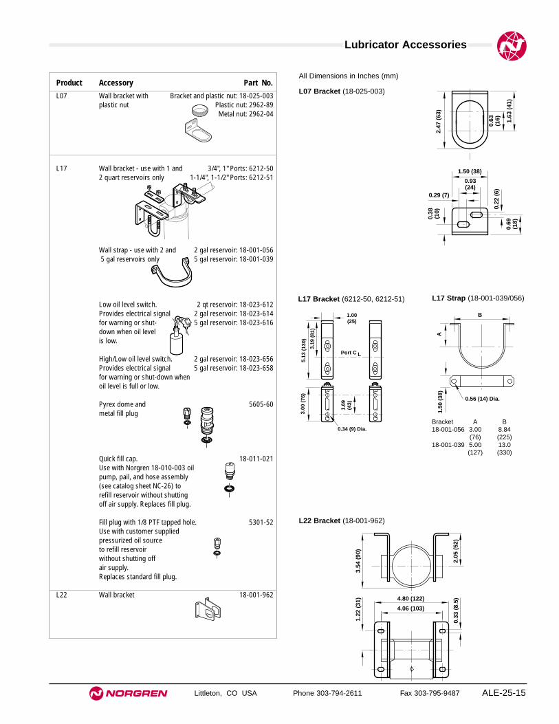
Lubricator Accessories
Littleton, CO USA Phone 303-794-2611 Fax 303-795-9487 ALE-25-15
Product Accessory Part No.L07 Wall bracket with Bracket and plastic nut: 18-025-003
plastic nut Plastic nut: 2962-89Metal nut: 2962-04
L17 Wall bracket - use with 1 and 3/4", 1" Ports: 6212-502 quart reservoirs only 1-1/4", 1-1/2" Ports: 6212-51
Wall strap - use with 2 and 2 gal reservoir: 18-001-0565 gal reservoirs only 5 gal reservoir: 18-001-039
Low oil level switch. 2 qt reservoir: 18-023-612Provides electrical signal 2 gal reservoir: 18-023-614for warning or shut- 5 gal reservoir: 18-023-616down when oil level is low.
High/Low oil level switch. 2 gal reservoir: 18-023-656Provides electrical signal 5 gal reservoir: 18-023-658for warning or shut-down whenoil level is full or low.
Pyrex dome and 5605-60metal fill plug
Quick fill cap. 18-011-021Use with Norgren 18-010-003 oil pump, pail, and hose assembly (see catalog sheet NC-26) to refill reservoir without shutting off air supply. Replaces fill plug.
Fill plug with 1/8 PTF tapped hole. 5301-52Use with customer supplied pressurized oil sourceto refill reservoir without shutting off air supply.Replaces standard fill plug.
L22 Wall bracket 18-001-962
All Dimensions in Inches (mm)
0.38
(10)
0.69
(18)
0.22
(6)
1.50 (38)
0.29 (7)
0.93(24)
2.47
(63
)
1.63
(41
)
0.63
(16)
L07 Bracket (18-025-003)
L17 Bracket (6212-50, 6212-51) L17 Strap (18-001-039/056)
1.00(25)
3.1
9 (8
1)
5.13
(13
0)
1.69
(43)
3.00
(76
)
Port C L
0.34 (9) Dia.
1.50
(38
)
B
0.56 (14) Dia.
A
0.33
(8.
5)2.
05 (
52)
3.54
(90
)1.
22 (
31)
4.06 (103)
4.80 (122)
L22 Bracket (18-001-962)
Bracket A B18-001-056 3.00 8.84
(76) (225)18-001-039 5.00 13.0
(127) (330)

Lubricator Accessories
Littleton, CO USA Phone 303-794-2611 Fax 303-795-9487ALE-25-16
Product Accessory Part No.L64 Wall bracket 7 ounce bowl: 74504-50
1 quart bowl: 74504-52
Tamper resistant 2117-01seal wire for sight-feed dome
Low oil level switch. 1 qt reservoir: 18-023-610Provides electrical signalfor warning or shut-down when oil level is low.
Quick fill cap. 18-011-024Use with Norgren 18-010-003 oil pump, pail, and hose assembly (see catalog sheet NC-26) to refill reservoir without shutting off air supply. Replaces fill plug.
Remote fill - use with 7 ounce reservoir only 5335-50Use with customer supplied pressurized oil source to automatically refill reservoir.
L68 Wall bracket 1/2", 3/4", 1", 1-1/4" Ports: 18-001-9781-1/2" Ports: Not Available
Tamper resistant 2117-01seal wire for sight-feed dome
Low oil level switch. 2 gal reservoir: 18-007-975Provides electrical signal 5 gal reservoir: 18-007-974for warning or shut-down when oil level is low.
Quick fill cap. 18-011-021Use with Norgren 18-010-003 oil pump, pail, and hose assembly (see catalog sheet NC-26) to refill reservoir without shutting off air supply. Replaces fill plug.
Remote fill - use with 1 qt reservoirs only 5335-52Use with customer supplied pressurized oil source to automatically refill reservoir.
5.63 (143)
4.49 (114)
0.32
(8.
2)3.
35 (
85)
0.43 (11) 0.57 (14.5)
3.66
(93
)
1.20
(30
.5)
1.89
(48
)
4.33
(11
0)
L64 Bracket(74504-50)
5.63 (143)
4.49 (114)
0.32
(8.
2)5.
09 (
129)
0.43 (11) 0.57 (14.5)
36.6
(93
)
12 (
30.5
)3.
62 (
92)
5.3
(134
)
L64 Bracket(74504-52)
8.19 (208)*
7.48 (190)*
3.94
(10
0)
1.97
(50)
2.84
(72
)
0.33
(8.
5)
0.59 (15)
7.48190 (190)
L68 Bracket(18-001-978)
All Dimensions in Inches (mm)

Lubricator Accessories
Littleton, CO USA Phone 303-794-2611 Fax 303-795-9487 ALE-25-17
Product Accessory Part No.L72 Wall bracket 4224-50
L73 Wall bracket 4424-50
Quick fill cap. 18-011-024Use with Norgren 18-010-003 oil pump, pail, and hose assembly (see catalog sheet NC-26) to refill reservoir without shutting off air supply. Replaces fill plug.
L74 Wall bracket 7 ounce bowl: 4324-501 quart bowl: 4324-51
Low oil level switch - use with 1 qt reservoir only18-023-610Provides electrical signalfor warning or shut-down when oil level is low.
Quick fill cap. 18-011-024Use with Norgren 18-010-003 oil pump, pail, and hose assembly (see catalog sheet NC-26) to refill reservoir without shutting off air supply. Replaces fill plug.
Remote fill - use with 7 ounce reservoir only 5335-50Use with customer supplied pressurized oil source to automatically refill reservoir.
0.24
(6)
0.20 (5)0.47(12)
Port CL
1.77 (45)
1.50
(38
)
2.36
(60
)
Port CL
1.54
(39
)
2.00
(51
)
0.79(20)
0.71 (18)
0.16 (4)
L72 Bracket (4224-50)
2.88 (73)2.
00 (
51)
3.25
(83
)
Port CL
0.20
(5)
0.77
(20)
0.24
(6)
1.97
(50
)
2.40
(61
)
0.16(4)
1.46(37)
1.00(25)
Port CL
L74 Bracket (4324-50)
1.10(28) 0.71
(18)0.16 (4)
0.24
(6)
0.28
(7)
0.74
(19)
2.40
(61)
1.89
(48)
2.37 (60)
2.64
(67)
1.50
(38)
Port CL
Port CL
L73 Bracket (4424-50)
All Dimensions in Inches (mm)

Lubricator Accessories
Littleton, CO USA Phone 303-794-2611 Fax 303-795-9487ALE-25-18
Product Accessory Part No.10-015 Wall bracket kit - use with 10-015 only. 18-001-009and Includes screws to attach lubricator10-065
Wall strap - use with 10-065 10-065-006: 18-001-05610-065-007: 18-001-039
Low oil level switch. 10-015-004: 18-023-020Provides electrical signal 10-005-005: 18-023-018for warning or shut- 10-065-006: 18-023-022down when oil level 10-065-007: 18-023-024is low.
Pyrex dome kit 1804-03
Quick fill cap. 18-011-006Use with Norgren 18-010-003 oil pump, pail, and hose assembly (see catalog sheet NC-26) to refill reservoir without shutting off air supply. Replaces fill plug.
Bowl guard for 18-012-00210-015-002 and 10-015-100
Streamline wye 1/4 PTF male to 1/4 PTF female: 18-006-016
10-028 Wall strap 2 gal reservoir: 18-001-0565 gal reservoir: 18-001-039
Quick fill cap. 18-011-008Use with Norgren 18-010-003 oil pump, pail, and hose assembly (see catalog sheet NC-26) to refill reservoir without shutting off air supply. Replaces fill plug.
Pyrex/aluminum dome 5605-50
10-076 Wall strap 2 gal reservoir: 18-001-0565 gal reservoir: 18-001-039
Pyrex/aluminum dome 5605-50
83 (3.25)
48 (1.88)
24 (0.95)
8 (0
.33)
45(1
.75)
57 (
2.25
)
54 (
2.13
)
75 (
2.94
)
Port CL
10-015 Bracket(18-001-009)
All Dimensions in Inches (mm)
10-028, 10-065, 10-076 Strap (18-001-039/056)
1.50
(38
)
B
0.56 (14) Dia.A
Bracket A B18-001-056 3.00 8.84
(76) (225)18-001-039 5.00 13.0
(127) (330)

Relief Valve Accessories
Littleton, CO USA Phone 303-794-2611 Fax 303-795-9487 ALE-25-19
Product Accessory Part No.V06 Wall bracket for V06 Bracket and plastic nut: 18-025-003
with plastic bonnet Plastic nut: 2962-89Metal nut: 2962-04
Wall bracket for V06 Bracket and metal nut: 18-001-021with brass bonnet Metal nut: 616-01
Tamper resistant knob 18-001-092
V07 Wall bracket with Bracket and plastic nut: 18-025-003plastic nut Plastic nut: 2962-89
Metal nut: 2962-04
Tamper resistant knob 18-001-092
V64 Wall bracket 74504-50
Muffler 1/2 PTF: MB004AR1/2: MB004B
Tamper resistant cap 1581-90
V68 Wall bracket 3/4", 1", 1-1/4" Ports: 18-001-9781-1/2" Ports: Not Available
Muffler 1/2 PTF: MB008AR1/2: MB008B
All Dimensions in Inches (mm)
0.38
(10)
0.69
(18)
0.22
(6)
1.50 (38)
0.29 (7)
0.93(24)
2.47
(63
)
1.63
(41
)
0.63
(16)
V06, V07 Bracket (18-025-003)
0.38
(10
)
0.69
(18)
0.22
(6)
1.38 (35)
0.35 (9)
0.69(18)
2.41
(61
)
1.63
(41
)
0.63
(16
)
1.0
(25)
V06 Bracket for Brass Bonnet (18-001-021)
5.63 (143)
4.49 (114)0.
32 (
8.2)
3.35
(85
)
0.43 (11) 0.57 (14.5)
3.66
(93
)
1.20
(30
.5)
1.89
(48
)
4.33
(11
0)
V64 Bracket (74504-50)
8.19 (208)*
7.48 (190)*
3.94
(10
0)
1.97
(50)
2.84
(72
)
0.33
(8.
5)
0.59 (15)
7.48 (190)
* Add 0.39" (10) for 1-1/4" ported yokes.
V68 Bracket (18-001-978)

Relief Valve Accessories
Littleton, CO USA Phone 303-794-2611 Fax 303-795-9487ALE-25-20
Product Accessory Part No.V72 Wall bracket 4224-50
Wall bracket/plastic nut Bracket and plastic nut: 74316-50Plastic nut: 4248-89Metal Nut: 4248-01
Tamper resistant cover and wire. Cover and wire: 4255-51Install over knob to help prevent Wire: 2117-01tampering of pressure setting.Use up to 2 padlocks with 5/16"(8mm) diameter shackle to secure cover. Lockout hasp may also be used.
Lockout hasp. 54547-01Allows use of up to 6 padlocks with5/16" (8mm) diameter shackle.
V74 Wall bracket 4324-50
Wall bracket/metal nut Bracket and metal nut: 4368-51Metal Nut: 4348-89
Tamper resistant cover and wire. Cover and wire: 4355-51Install over knob to help prevent Wire: 2117-01tampering of pressure setting.Use up to 4 padlocks with 5/16"(8mm) diameter shackle to secure cover. Lockout hasp may also be used.
Lockout hasp. 54547-01Allows use of up to 6 padlocks with5/16" (8mm) diameter shackle.
0.24
(6)
0.20 (5)0.47(12)
Port CL
1.77 (45)
1.50
(38
)
2.36
(60
)
Port CL
1.54
(39
)
2.00
(51
)
0.79(20)
0.71 (18)
0.16 (4)
V72 Bracket (4224-50)
1.1
(28)
1.5
(38)
1.9 (49)
1.0
(25)
1.0
(25)
1.2(30)
0.3 (8)
0.2
(4)
V72 Neck Bracket (74316-50)
All Dimensions in Inches (mm)
2.88 (73)
2.00
(51
)
3.25
(83
)
Port CL
0.20
(5)
0.77
(20)
0.24
(6)
1.97
(50
)
2.40
(61
)
0.16(4)
1.46(37)
1.00(25)
Port CL
V74 Bracket (4324-50)
3.37
(86)
2.06
(52)
0.9
(23)
2.2 (56)
3.5 (89)
0.95(24)
0.28
(7)
V74 Neck Bracket (4368-51)
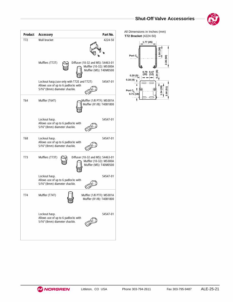
Shut-Off Valve Accessories
Littleton, CO USA Phone 303-794-2611 Fax 303-795-9487 ALE-25-21
Product Accessory Part No.T72 Wall bracket 4224-50
Mufflers (T72T) Diffuser (10-32 and M5): 54463-01Muffler (10-32): MS000AMuffler (M5): T40M0500
Lockout hasp.(use only with T72E and T72T) 54547-01Allows use of up to 6 padlocks with5/16" (8mm) diameter shackle.
T64 Muffler (T64T) Muffler (1/8 PTF): MS001AMuffler (R1/8): T40B1800
Lockout hasp. 54547-01Allows use of up to 6 padlocks with5/16" (8mm) diameter shackle.
T68 Lockout hasp. 54547-01Allows use of up to 6 padlocks with5/16" (8mm) diameter shackle.
T73 Mufflers (T73T) Diffuser (10-32 and M5): 54463-01Muffler (10-32): MS000AMuffler (M5): T40M0500
Lockout hasp. 54547-01Allows use of up to 6 padlocks with5/16" (8mm) diameter shackle.
T74 Muffler (T74T) Muffler (1/8 PTF): MS001AMuffler (R1/8): T40B1800
Lockout hasp. 54547-01Allows use of up to 6 padlocks with5/16" (8mm) diameter shackle.
0.24
(6)
0.20 (5)0.47(12)
Port CL
1.77 (45)
1.50
(38
)
2.36
(60
)
Port CL
1.54
(39
)
2.00
(51
)
0.79(20)
0.71 (18)
0.16 (4)
T72 Bracket (4224-50)All Dimensions in Inches (mm)

Smooth Start and Directional Control Valve Accessories
Littleton, CO USA Phone 303-794-2611 Fax 303-795-9487ALE-25-22
Product Accessory Part No.P72 Mufflers for P72C and P72F 1/4 PTF: MB002A
R1/4: MB002B
Lockout hasp for P72F. 54547-01Allows use of up to 6 padlocks with5/16" (8mm) diameter shackle.
P64F Wall bracket 74504-50
Muffler 1/2 PTF: MB004AR1/2: MB004B
Lockout hasp. 54547-01Allows use of up to 6 padlocks with5/16" (8mm) diameter shackle.
P68F Wall bracket 3/4", 1", 1-1/4" Ports: 18-001-9781-1/2" Ports: Not Available
Muffler 1” PTF: MB008AR1 : MB008B
Lockout hasp. 54547-01Allows use of up to 6 padlocks with5/16" (8mm) diameter shackle.
P74 Wall bracket 4324-50
Mufflers for P74C and P74F 1/2 PTF: MB004AR1/2: MB004B
Lockout hasp for P74F and P74C with lockout slide: 54547-01Allows use of up to 6 padlocks with5/16" (8mm) diameter shackle.
5.63 (143)
4.49 (114)
0.32
(8.
2)3.
35 (
85)
0.43 (11) 0.57 (14.5)
3.66
(93
)
1.20
(30
.5)
1.89
(48
)
4.33
(11
0)
P64 Bracket(74504-50)
All Dimensions in Inches (mm)
8.19 (208)*
7.48 (190)*
3.94
(10
0)
1.97
(50)
2.84
(72
)
0.33
(8.
5)
0.59 (15)
7.48190 (190)
P68 Bracket(18-001-978)
2.88 (73)
2.00
(51
)
3.25
(83
)
Port CL
0.20
(5)
0.77
(20)
0.24
(6)
1.97
(50
)
2.40
(61
)
0.16(4)
1.46(37)
1.00(25)
Port CL
P74 Bracket (4324-50)
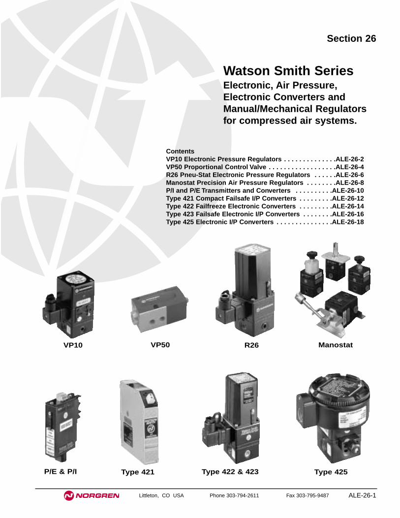
Littleton, CO USA Phone 303-794-2611 Fax 303-795-9487 ALE-26-1
Section 26
ContentsVP10 Electronic Pressure Regulators . . . . . . . . . . . . . .ALE-26-2VP50 Proportional Control Valve . . . . . . . . . . . . . . . . . .ALE-26-4R26 Pneu-Stat Electronic Pressure Regulators . . . . . .ALE-26-6Manostat Precision Air Pressure Regulators . . . . . . . .ALE-26-8P/I and P/E Transmitters and Converters . . . . . . . . . .ALE-26-10Type 421 Compact Failsafe I/P Converters . . . . . . . . .ALE-26-12Type 422 Failfreeze Electronic Converters . . . . . . . . .ALE-26-14Type 423 Failsafe Electronic I/P Converters . . . . . . . .ALE-26-16Type 425 Electronic I/P Converters . . . . . . . . . . . . . . .ALE-26-18
Watson Smith SeriesElectronic, Air Pressure,Electronic Converters andManual/Mechanical Regulatorsfor compressed air systems.
VP10 R26 ManostatVP50
P/E & P/I Type 421 Type 422 & 423 Type 425

Littleton, CO USA Phone 303-794-2611 Fax 303-795-9487
VP10
● Reliable, rugged proportional I/P and E/P converters
● Suitable for a wide range of applications
● Excellent accuracy
● High flow versions
● NEMA4 environmental protection in normal operation
Electronic Pressure Regulator
ALE-26-2
Pressure range and input signal optionsPart Number Control signal Output pressureVP1001100A00 0-10 V 3-15 psi (0.2-1 bar)VP1001400A00 4-20 mA 3-15 psi (0.2-1 bar)VP1002100A00 0-10 V 3-30 psi (0.2-2 bar)VP1002400A00 4-20 mA 3-30 psi (0.2-2 bar)VP1004100A00 0-10 V 3-60 psi (0.2-4 bar)VP1004400A00 4-20 mA 3-60 psi (0.2-4 bar)VP1006101A00 0-10 V 3-90 psi (0.2-6 bar)VP1006401A00 4-20 mA 3-90 psi (0.2-6 bar)VP1008101A00 0-10 V 3-120 psi (0.2-8 bar)VP1008401A00 4-20 mA 3-120 psi (0.2-8 bar)
Electrical Information
General Information
Electromagnetic compatibility This is a passive electromagnetic instrument and isunaffected by interfering high frequency signals
Electrical signal Two wire version 4-20 mA or 0-10 VThree wire version requires 12-24 V d.c. supply
Connections 30 mm square connector DIN 43650 provided, mountablein four directions (alternative connections available)
ISO Symbols

VP10 Electronic Pressure Regulator
Littleton, CO USA Phone 303-794-2611 Fax 303-795-9487 ALE-26-3
All Dimensions in Inches (mm)
Technical dataMedium:
Oil free, dry air, filtered to 5 micronOutput pressure:
3-15 psig (0.2-1.0 bar), 3-30 psig (0.2-2.0 bar), 3-60 psig (0.2-4.0 bar), 2-120 psig (0.14-8 bar) three wire version
Flow capacity: Up to 10 scfm (300 l/min)Air consumption
<60 psig (<4 bar): 0.03 scfm (0.85 l/min) typical>60 psig (>4 bar): 0.06 scfm (1.75 l/min) typical
Operating pressure:At least 10 psig (0.7 bar) above maximum required output pressure
Connections: NPT 1/4"Operating temperature: -4° to 160°F (-20°C to 70°C)Response time
<30 psig (<2 bar): less than 0.5 seconds for 10-90% step change>30 psig (>2 bar): 2 seconds for 10-90% step change
Total error:±0.5% of span (typical, independent error includes the combined effect ofnon-linearity, hysteresis, deadzone and repeatability)
Temperature effect:Typically 0.1% of span/°F for span and zero over operating range
Supply sensitivity:>0.025% span output change per % supply pressure change
Failure mode:Signal falls to bleed pressure when electrical supply fails
Mounting:Integral surface mounting bracket provided for preferred vertical mounting.50 mm pipe mounting kit available
Material of construction:Zinc die-casting passivated and epoxy paint, nitrile diaphragms, stainless steel/nylon flapper nozzle and supply valve
Mass: 3.3 lbs (1500g) approx.
2 (5
1)
4.72
(12
0)
1.57 (40) 2.13 (54)
2.9 (73)
2.13
(54
)
Range or Span(Typical)
Mounting Holes.26 (6.5)
Removable Orifice
Front View
Plug Orients 4-Ways
Supply In Output
1.63
(42
).7
5 (1
9) C
RS
.87 (22)
Rear View
Mtg Bracket Holes Ø.15 (3.7)
Typical Performance CharacteristicsFORWARD FLOW CHARACTERISTICS
Supply Pressure 100 psig (7 bar)
0 100 200 300 400 500 600 l/min
FLOW
0 3.5 7 10.5 14 17.5 21 scfm
OU
TL
ET
PR
ES
SU
RE
8
6
4
2
0
bar
100
80
60
40
20
0
psi
g
120
RELIEF FLOW CHARACTERISTICSSupply Pressure 100 psig (7 bar)
-700 -600 -500 -400 -300 -200 -100 0 N l/m in
FLOW
25 21 17.5 14 10.5 7 3.5 0 scfm
OU
TL
ET
PR
ES
SU
RE
8
6
4
2
0
bar
100
80
60
40
20
0
psi
g
120
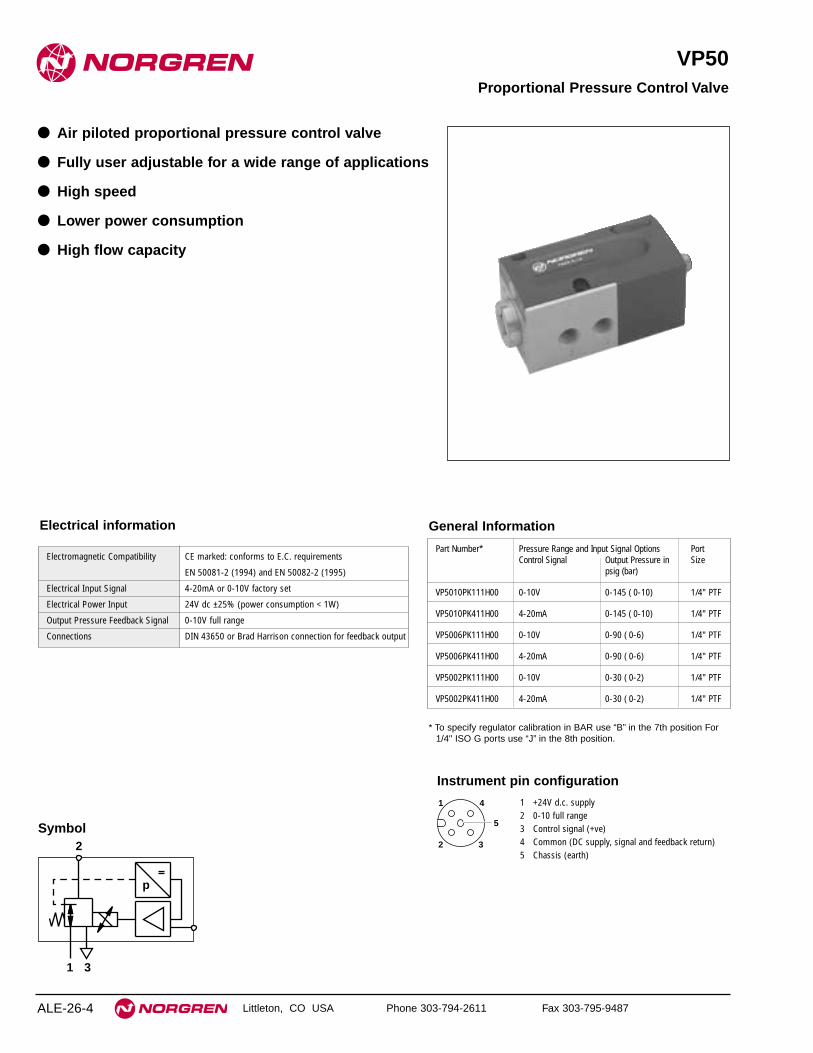
Littleton, CO USA Phone 303-794-2611 Fax 303-795-9487
VP50
● Air piloted proportional pressure control valve
● Fully user adjustable for a wide range of applications
● High speed
● Lower power consumption
● High flow capacity
Proportional Pressure Control Valve
ALE-26-4
2
1 3
p
Symbol
General Information
Electromagnetic Compatibility CE marked: conforms to E.C. requirements
EN 50081-2 (1994) and EN 50082-2 (1995)
Electrical Input Signal 4-20mA or 0-10V factory set
Electrical Power Input 24V dc ±25% (power consumption < 1W)
Output Pressure Feedback Signal 0-10V full range
Connections DIN 43650 or Brad Harrison connection for feedback output
Electrical information
Part Number* Pressure Range and Input Signal Options PortControl Signal Output Pressure in Size
psig (bar)
VP5010PK111H00 0-10V 0-145 ( 0-10) 1/4" PTF
VP5010PK411H00 4-20mA 0-145 ( 0-10) 1/4" PTF
VP5006PK111H00 0-10V 0-90 ( 0-6) 1/4" PTF
VP5006PK411H00 4-20mA 0-90 ( 0-6) 1/4" PTF
VP5002PK111H00 0-10V 0-30 ( 0-2) 1/4" PTF
VP5002PK411H00 4-20mA 0-30 ( 0-2) 1/4" PTF
1
2 3
4
5
1 +24V d.c. supply2 0-10 full range3 Control signal (+ve)4 Common (DC supply, signal and feedback return)5 Chassis (earth)
Instrument pin configuration
* To specify regulator calibration in BAR use “B” in the 7th position For1/4" ISO G ports use “J” in the 8th position.
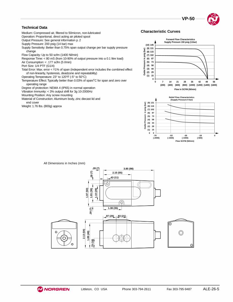
VP-50
Littleton, CO USA Phone 303-794-2611 Fax 303-795-9487 ALE-26-5
Technical DataMedium: Compressed air, filtered to 50micron, non-lubricatedOperation: Proportional, direct acting air piloted spoolOutput Pressure: See general information p. 2Supply Pressure: 200 psig (14 bar) maxSupply Sensitivity: Better than 0.75% span output change per bar supply pressure
changeFlow Capacity: Up to 50 scfm (1400 Nl/min)Response Time: < 80 mS (from 10-90% of output pressure into a 0.1 litre load)Air Consumption: < .177 scfm (5 l/min)Port Size: 1/4 PTF (G1/4)Total Error: Max. error < ±1% of span (independent error includes the combined effect
of non-linearity, hysteresis, deadzone and repeatability)Operating Temperature: 23° to 120°F (-5° to 50°C)Temperature Effect: Typically better than 0.03% of span/˚C for span and zero over
operating rangeDegree of protection: NEMA 4 (IP65) in normal operationVibration Immunity: < 3% output shift for 3g 10-2000HzMounting Position: Any screw mountingMaterial of Construction: Aluminum body, zinc diecast lid and
end coverWeight: 1.76 lbs. (800g) approx
0 7 14 21 28 35 42 49 56 (200) (400) (600) (800) (1000) (1200) (1400) (1600)
Flow in SCFM (Nl/min)
Forward Flow CharacteristicsSupply Pressure 150 psig (11bar)
Out
let P
ress
ure
in p
sig
(bar
)
145
131
115
102
87
73
58
44
29
15
0
(10)
(9)
(8)
(7)
(6)
(5)
(4)
(3)
(2)
(1)
(-2000) (-1500) (-1000) (-500)
Relief Flow Characteristics(Supply Pressure 9 bar)
Flow SCFM (Nl/min)
(9)
(8)
(7)
(6)
(5)
(4)
(3)
(2)
(1)
0
Ou
tlet
Pre
ssu
re i
n p
sig
(b
ar) 131
116
102
87
73
58
44
29
15
0-70 -53 -35 -18 0
Characteristic Curves
2.15 (55)
3.85 (98).28 (7)
1.10
(28
)
1.97
(50
)
.75
(19)1.
89 (
48)
2.13
(54
)
.97 (25) .83 (21)
1.81
(36
).2
8 (7
)
.43 (11)
1.38 (35)
.28
(7)
All Dimensions in Inches (mm)
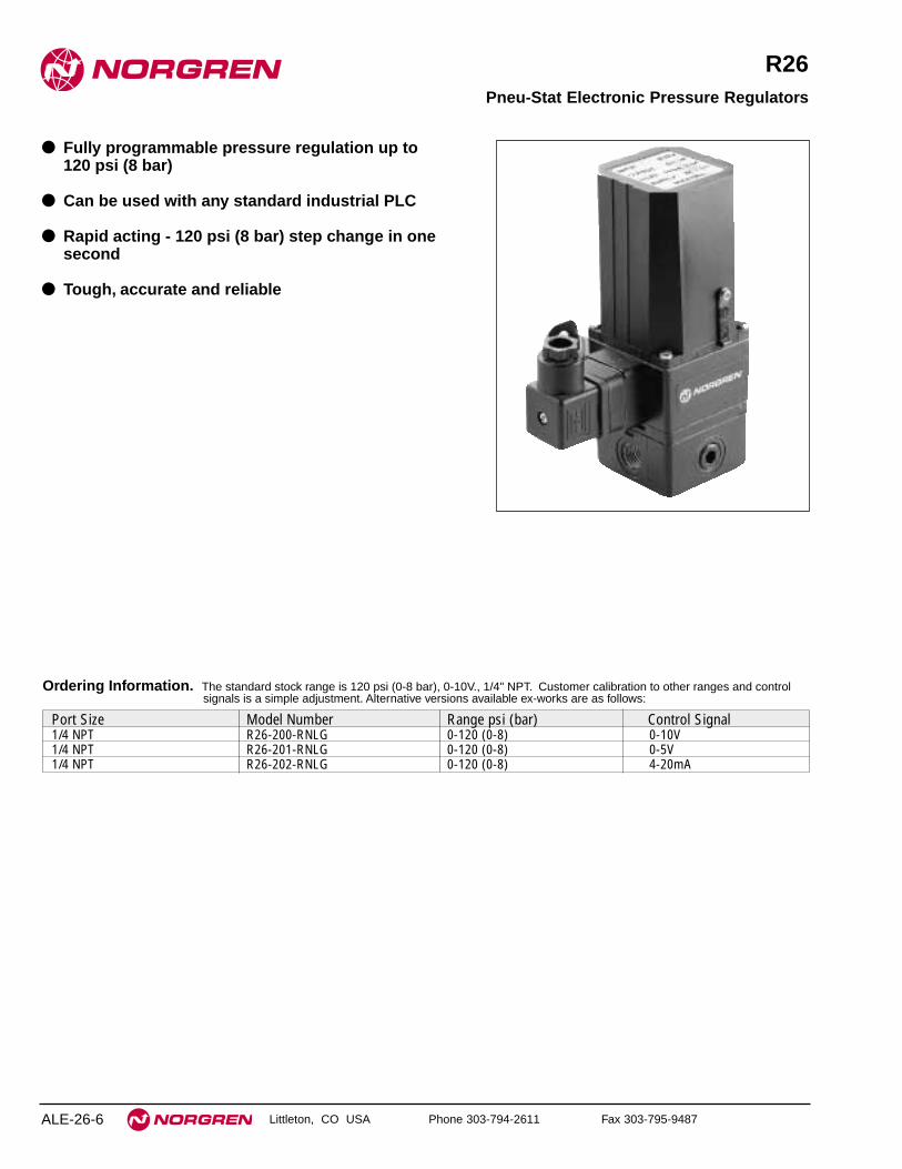
Littleton, CO USA Phone 303-794-2611 Fax 303-795-9487
R26
● Fully programmable pressure regulation up to 120 psi (8 bar)
● Can be used with any standard industrial PLC
● Rapid acting - 120 psi (8 bar) step change in onesecond
● Tough, accurate and reliable
Pneu-Stat Electronic Pressure Regulators
ALE-26-6
Port Size Model Number Range psi (bar) Control Signal1/4 NPT R26-200-RNLG 0-120 (0-8) 0-10V1/4 NPT R26-201-RNLG 0-120 (0-8) 0-5V1/4 NPT R26-202-RNLG 0-120 (0-8) 4-20mA
Ordering Information. The standard stock range is 120 psi (0-8 bar), 0-10V., 1/4" NPT. Customer calibration to other ranges and controlsignals is a simple adjustment. Alternative versions available ex-works are as follows:

Technical DataSupply:
Clean dry air (filtered to 5 µ non-condensing, oil free)Up to 150 psi (10 bar)
Output:0-120 psi (0-8 bar) [user adjustable down to 0-60 psi (0-4 bar)]At zero control signal,< 0.05 bar.
Electrical supply:Nominal 24V dc, limits 15-30V dc. Max current 100 mA
Control signal:4-20 mA; 250 ohms 0-5V; 10 k ohms 0-10V; 10k ohms
Connections:3 wire connection, 1.24V dc supply 2. Control Signal 3. Common
Air flow:Consumption <.2 scfm (<5 l/m), Capacity >20 scfm (> 600 l/min) forward at
60 psi (4 bar), 10 scfm (300 l/min) relief at 60 psi (4 bar)
MaterialEnclosure:
Case manufactured from zinc and reinforced plastic, finished with a blackepoxy paint finish.
Mounting:The Pneu-Stat can be mounted ina ny orientation, a mounting bracket isprovided.
Pneumatic connections:1/4 NPT. Front and rear facing Ports 1/4 NPT
Electrical connections:30 mm square connector to DIN 43650. Orientable in four ways at 90°. Matingconnector supplied.
Controls:Span and zero - externalRange select switches - internal
Weight: 1.75 lbs (800g)
R26 Pneu-Stat Electronic Pressure Regulators
Littleton, CO USA Phone 303-794-2611 Fax 303-795-9487 ALE-26-7
All Dimensions in Inches (mm)
120 psi(8 bar)
1 sec. ➝➝
120 psi (8 bar)
0 100%
Response timeinto a 1 liter load
Accuracy
Out
Control signal
< 2% error
3.30
(84
)
2.87 (73)
2.20 (56)
5.80
(14
7.5)
3.20
(81
.5)
2-Holes Ø.25
5.09 (129.5)
1/4 NPT PORTS
PG9 .24 - .31 (6 - 8) cable
Span
Zero
In Out
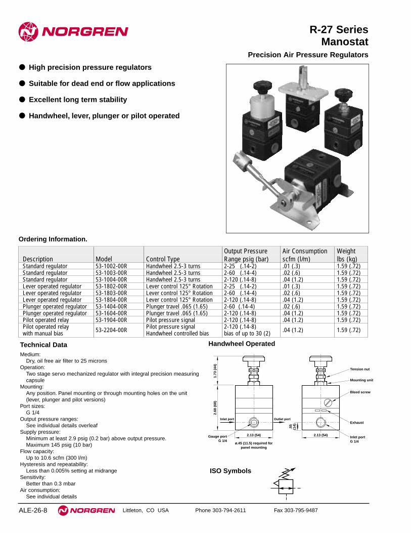
Littleton, CO USA Phone 303-794-2611 Fax 303-795-9487
R-27 SeriesManostat
● High precision pressure regulators
● Suitable for dead end or flow applications
● Excellent long term stability
● Handwheel, lever, plunger or pilot operated
Precision Air Pressure Regulators
Technical DataMedium:
Dry, oil free air filter to 25 micronsOperation:
Two stage servo mechanized regulator with integral precision measuringcapsule
Mounting:Any position. Panel mounting or through mounting holes on the unit(lever, plunger and pilot versions)
Port sizes:G 1/4
Output pressure ranges:See individual details overleaf
Supply pressure:Minimum at least 2.9 psig (0.2 bar) above output pressure.Maximum 145 psig (10 bar)
Flow capacity:Up to 10.6 scfm (300 l/m)
Hysteresis and repeatability:Less than 0.005% setting at midrange
Sensitivity:Better than 0.3 mbar
Air consumption:See individual details
ALE-26-8
Output Pressure Air Consumption WeightDescription Model Control Type Range psig (bar) scfm (l/m) lbs (kg)Standard regulator 53-1002-00R Handwheel 2.5-3 turns 2-25 (.14-2) .01 (.3) 1.59 (.72)Standard regulator 53-1003-00R Handwheel 2.5-3 turns 2-60 (.14-4) .02 (.6) 1.59 (.72)Standard regulator 53-1004-00R Handwheel 2.5-3 turns 2-120 (.14-8) .04 (1.2) 1.59 (.72)Lever operated regulator 53-1802-00R Lever control 125° Rotation 2-25 (.14-2) .01 (.3) 1.59 (.72)Lever operated regulator 53-1803-00R Lever control 125° Rotation 2-60 (.14-4) .02 (.6) 1.59 (.72)Lever operated regulator 53-1804-00R Lever control 125° Rotation 2-120 (.14-8) .04 (1.2) 1.59 (.72)Plunger operated regulator 53-1404-00R Plunger travel .065 (1.65) 2-60 (.14-4) .02 (.6) 1.59 (.72)Plunger operated regulator 53-1604-00R Plunger travel .065 (1.65) 2-120 (.14-8) .04 (1.2) 1.59 (.72)Pilot operated relay 53-1904-00R Pilot pressure signal 2-120 (.14-8) .04 (1.2) 1.59 (.72)Pilot operated relay 53-2204-00R Pilot pressure signal 2-120 (.14-8) .04 (1.2) 1.59 (.72)with manual bias Handwheel controlled bias bias of up to 30 (2)
Ordering Information.
ISO Symbols
Handwheel Operated
2.13 (54)
ø.45 (11.5) required forpanel mounting
Gauge portG 1/4
Inlet port G 1/4
Exhaust
Bleed screw
Mounting unit
Tension nut
2.13 (54)
1.73
(44
)2.
68 (
68)
.55
(14)
Inlet port Outlet port

R27 Series Precision Air Pressure Regulators
Littleton, CO USA Phone 303-794-2611 Fax 303-795-9487 ALE-26-9
All Dimensions in Inches (mm)
FORWARD FLOW CHARACTERISTICS102 psig (8 bar) Supply
0 200 400 600 l/min
0 7 14 cfm
AIR FLOW
OU
TL
ET
PR
ES
SU
RE
8
6
4
2
0
bar
100
80
60
40
20
0
psi
g
120
RELIEF FLOW CHARACTERISTICS102 psig (8 bar) Supply
400 300 200 100 0 l/min
14 10.5 7 3.5 0 cfm
AIR FLOW
OU
TL
ET
PR
ES
SU
RE
8
6
4
2
0
bar
100
80
60
40
20
0
psi
g
120
Typical Performance Characteristics2.13 (54 )
2.32 (59)
1.14 (29)
1.26 (32)
2.68
(59
)1.
06 (
27)
.51
(14)
1.06
(27
)
.51
(13)
Gauge portG 1/4
Air connectionsG 1/4
Bias adjustment(factory set)
Signal Port1/4" NPT
2 mounting holes ø.37 (9.5)
Exhaust
Bleed screw
Inlet port Outlet port
Gauge portG 1/4
Air connectionsG 1/4
Signal port1/8" BSP
2 panel mountingholes tapped2BA 10 deep
Exhaust
Bleed screw
.55
(14)
2.13 (54)
2.36
(60
)
1.10
(28
)
.71
(18)
2.68
(68
)
Inlet port Outlet port
Gauge portG 1/4
Exhaust
ø.28 (7)Air connectionsG 1/4
Bleed screws
Ball bearingø.37 (9.5)
2.13
(54
)
ø.75 (19)
3.27 (83)
4.02 (102)
.25 (6.4)
Dome Fitting
.31
(8)
.25
(6.4
)
R16
2.68
(68
)
2.13
(54
)
1.38
(35
)
Inlet port Outlet port
Clevis fitting
Clevis withø.13 (3.2) pin
2.68 (68)
3.43 (87)
4.13 (105)
1.97 (50)
125°
Zero Range
2.99 (76)
3.62
(92)
1.38 (35)
Loosen nut toadjust zero and
range stops
Adjustable zeroand range stops
Inlet port Outlet port
ExhaustAir connectionsG 1/4
4 fixing holes ø.25 (6.3) Bleed screws
Pilot Operated
Pilot Operated with Bias
Lever Operated
Plunger Operated
Diaphragm Repair KitsType Part numberUnits up to 25 psig 53 1000 95RUnits up to 60 psig 53 1000 99RUnits up to 120 psig 53 1000 98RTamperproof Nut 53 1000 97RWall Mounting Bracket 53 ABR 00700

Littleton, CO USA Phone 303-794-2611 Fax 303-795-9487
P/I & P/E
● These instruments convert pneumatic pressures intoelectrical signals for use with data loggers,computers and microprocessors
● Type 68 is a two-wire pressure/current device
● Type 69 a three-wire pressure/voltage type
● Both use only non-critical power supplies and can besupplied weatherproof to IP65
Transmitters & Converter Types 68 & 69
ALE-26-10
P/I Type 68 P/E Type 69Standard Weatherproof Standard Weatherproof Range536801 00 536801 10 536901 00 536901 11 3-15 psig536815 00 536815 10 536915 00 536915 11 0-150 psig536816 00 536816 10 536916 00 536916 11 0-100 psig536896 00 536896 10 536996 00 536996 11 0-200m bar536893 00 536893 10 536993 00 536993 11 0-200m bar536821 00 536821 10 536921 00 536921 11 0.2-1 bar536833 00 536833 10 536933 00 536933 11 0-4 bar536835 00 536835 10 536935 00 536935 11 0-10 bar536836 00 536836 10 536936 00 536936 11 0-7 bar536837 00 536837 10 536937 00 536937 11 0-6 bar536841 00 536841 10 536941 00 536941 11 20-100 kPa536855 00 536855 10 536955 00 536955 11 0-1000 kPa536856 00 536856 10 536956 00 536956 11 0-700 kPa536886 00 536886 10 536986 00 536986 11 0-100 in wg536888 00 536888 10 536988 00 536988 11 0-200 in wg
Ordering Information.
Intrinsically Safe
P/I Type 68 P/E Type 69Standard Weatherproof Standard Weatherproof Range536801 01 536801 11 536901 01 536901 11 3-15 psig536821 01 536821 11 536921 01 536921 11 0-150 psig
NOTE:1. Intrinsically safe models are available for all standard and weather proof instruments.2. Other pressure ranges between 50millibar and 10 bar are available to order. Please consult factory for availability.3. Type 69 P/E models - voltage ranges other than 0-10V are available to special order.4. All models supplied complete with DIN rail clip and mounting plate.5. Low pressure models within the ranges 0-25inwg to 0-50in wg. 0-1 psig to 0-2 psig and 0-70mbar to 0-150mbar are also available please ask
for further details.6. A range of models with temperature compensation -4° to 104°F (-20° to 40°C) are available for natural gas applications to special order.

Technical DataPneumatic:Pressure media:
Dry, non corrosive air or gas. The units are not suitable for continuous liquidexposure
Pressure ranges:See ordering information Units with Full Scale ranges between 1 psig (70m bar)and 150 psig (10 bar) are available to special order
Over pressure:At least 100% with negligible calibration error, except for 150 psig models whichare 200 psig maximum
Consumption: Nil ØTemperature range: 15° to 140°F (-10° to 60°C)
Electrical:Maximum Supply
Voltage: 35V for 1 secondReverse voltage: -50V continuousProtection: 500V d.c. (components to case)
Type 68 P/ISupply voltage: 9-30V continuousOutput: 4-20mAVoltage drop: 9V minute (across unit)Load resistance: 750 ohm maximum (24V supply)
Type 69 P/ESupply voltage: 12-30 V continuousOutput: 0-10V Other voltage ranges to special orderCurrent: 5mA nominalLoad resistance: 2000 ohm minimum
MaterialsCasing: Extruded aluminum, zinc diecast end platesPCB: Epoxy glass fiberPneumatic connection: 1/8" NPTTransducer: Composite construction, mainly nickel, aluminum, Kovar, silicon
rubber/gelWeight: 200gFinish: Black stove enamel
Transmitters & Converter Types 68 & 69
Littleton, CO USA Phone 303-794-2611 Fax 303-795-9487 ALE-26-11
All Dimensions in Inches (mm)
2.32 (59) .08 (2)
.24 (6)
2.32 (59) .63 (16)
2 x
ø.1
3 (3
.2)
1.26
(32
)
.87
(22)
Fix
ing
ho
les
40 C
TR
S
.87
(22)
.59 (15)
Surface mountingplate (optional)
PneumaticConnection
1/8" NPT
DIN rail mounting c
Range set
Klippon TerminalStandard Models
Zero set
4.06
(10
3).5
1(1
3)

Littleton, CO USA Phone 303-794-2611 Fax 303-795-9487
Type 421
● A rugged, electronic I/P converter designed for highdensity rail or manifold mounting, at a spacing ofonly 1" (25mm)
● Advanced electronic control using surface mountelectronics and a precision pressure transducer andoffers excellent performance characteristics
● Unlike most I/P converters which use fragileelectromechanical pressure control devices, the 421employs a high sensitivity microminiature Reedexvalve for pressure control
● Great reliability, long life, freedom from vibrationeffects, and are significantly less prone tomechanical derangement than older conventionaldesigns
● Can be conveniently mounted on DIN rail, or surfacemounted, or onto a high density manifold, whicheliminates much plumbing
Compact Failsafe Rail Mount I/P Converter
Ordering InformationStandard models:
4-20mA input, forward action, Terminal connector
Options to special order:Other pressure rangesManifold mounting system
ALE-26-12
CertificationAll instruments are tested on the Watson Smith ATEsystem. An individual test certificate is provided at no extracharge.
AccuracyControl characteristics*:
Linear, pressure proportional to signal
Maximum error*:(Combined effect of non-linearity, hysteresis, deadzone& repeatability)Within ±0.5% span of a terminally based straight line
Hysteresis + resolution*: Less than 0.1% span
Supply pressure effect*: See graph
Temperature effect: (span & zero)Typically less than 1% FS over compensated range
Long term stability:Typically <0.5% span per annum
* Parameters marked with * are tested on every unit by computercontrolled test equipment. Other parameters are typical.
Outputs Model Number0.2-1 bar 53AB21003-15 psig 53AB0100
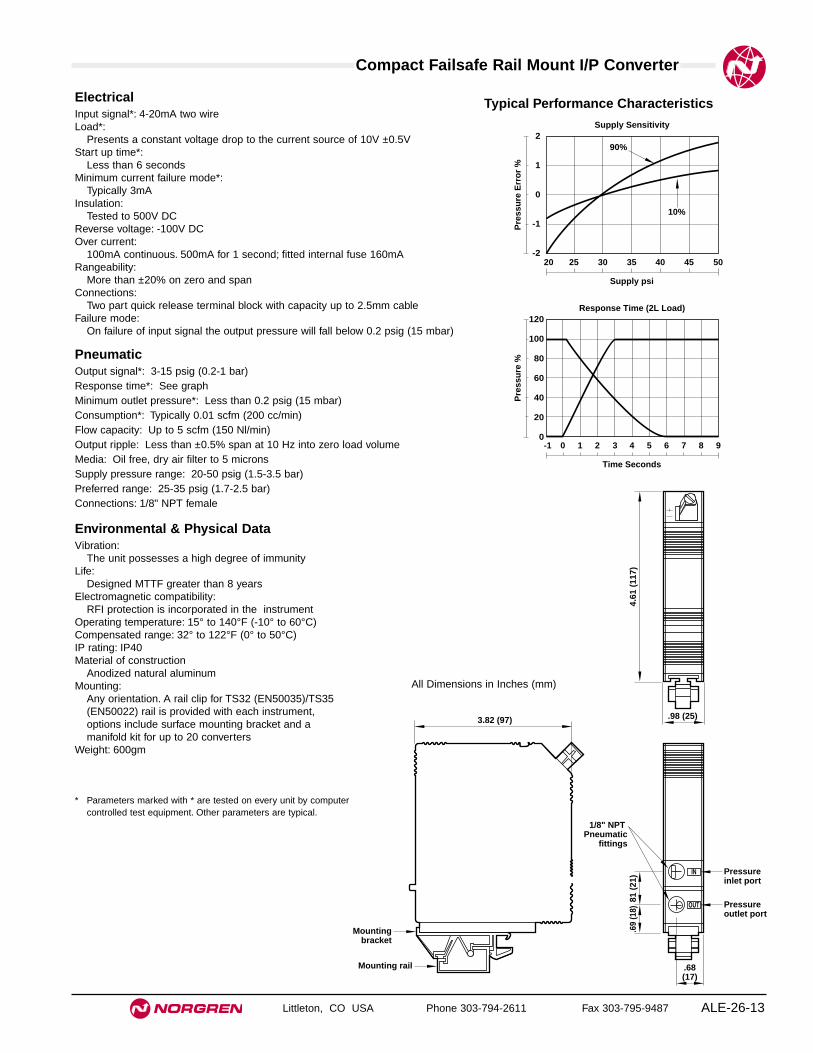
Compact Failsafe Rail Mount I/P Converter
Littleton, CO USA Phone 303-794-2611 Fax 303-795-9487 ALE-26-13
ElectricalInput signal*: 4-20mA two wireLoad*:
Presents a constant voltage drop to the current source of 10V ±0.5VStart up time*:
Less than 6 secondsMinimum current failure mode*:
Typically 3mAInsulation:
Tested to 500V DCReverse voltage: -100V DCOver current:
100mA continuous. 500mA for 1 second; fitted internal fuse 160mARangeability:
More than ±20% on zero and spanConnections:
Two part quick release terminal block with capacity up to 2.5mm cableFailure mode:
On failure of input signal the output pressure will fall below 0.2 psig (15 mbar)
PneumaticOutput signal*: 3-15 psig (0.2-1 bar)Response time*: See graphMinimum outlet pressure*: Less than 0.2 psig (15 mbar)Consumption*: Typically 0.01 scfm (200 cc/min)Flow capacity: Up to 5 scfm (150 Nl/min)Output ripple: Less than ±0.5% span at 10 Hz into zero load volumeMedia: Oil free, dry air filter to 5 micronsSupply pressure range: 20-50 psig (1.5-3.5 bar)Preferred range: 25-35 psig (1.7-2.5 bar)Connections: 1/8" NPT female
Environmental & Physical DataVibration:
The unit possesses a high degree of immunityLife:
Designed MTTF greater than 8 yearsElectromagnetic compatibility:
RFI protection is incorporated in the instrumentOperating temperature: 15° to 140°F (-10° to 60°C)Compensated range: 32° to 122°F (0° to 50°C)IP rating: IP40Material of construction
Anodized natural aluminumMounting:
Any orientation. A rail clip for TS32 (EN50035)/TS35(EN50022) rail is provided with each instrument,options include surface mounting bracket and amanifold kit for up to 20 converters
Weight: 600gm
* Parameters marked with * are tested on every unit by computercontrolled test equipment. Other parameters are typical.
Supply Sensitivity
90%
20 25 30 35 40 45 50
Supply psi
Pre
ssu
re E
rro
r %
2
1
0
-1
-2
10%
Response Time (2L Load)
-1 0 1 2 3 4 5 6 7 8 9
Time Seconds
Pre
ssu
re %
120
100
80
60
40
20
0
Typical Performance Characteristics
3.82 (97)
Mountingbracket
Pressureinlet port
Pressureoutlet port
1/8" NPT Pneumatic
fittings
Mounting rail .68(17)
.98 (25)
81 (
21)
4.61
(11
7).6
9 (1
8)
All Dimensions in Inches (mm)

Littleton, CO USA Phone 303-794-2611 Fax 303-795-9487
Type 422
● A major advance in I/P converter design, offeringfailfreeze in addition to conventional I/P features
● Advanced electronic control and a precision pressuretransducer to achieve outstanding performance
● Intended for field application in which ruggedconstruction, vibration immunity, weatherproofingand reliability are essential, together with theenhanced system safety gained from its failfreezecharacteristic
● Two wire operation from a 4-210mA control signalwith output pressures up to 120 psig (8 bar) asstandard
Failfreeze Electronic Converter
ALE-26-14
Ordering InformationStandard models:
4-20mA input, forward action, DIN connector
Options to special order:Other pressure rangesConduit entry with flying leadsType N Certification50mm pipe mounting bracket1/8" NPT pneumatic connectionsI.S. Certification
Outputs Model Number0.2-1 bar 53AC21003-15 psig 53AC01000.2-8 bar 53AC24003-120 psig 53AC0400
CertificationAll instruments are tested on the Watson Smith ATEsystem. An individual test certificate is provided at no extracharge.
Hazardous area approvals:The 422 is available with Type NIIT6 approval to BS69411988 or Type EEx ia IICT4 approval for intrinsically safeapplications
AccuracyControl characteristics*:
Linear, pressure proportional to signal
Maximum error*:(Combined effect of non-linearity, hysteresis, deadzone& repeatability)±0.5% span of a terminally based straight line (lowpressure), 1% (high pressure)
Supply pressure effect*: Negligible
Temperature effect: (span & zero)Typically less than 1% span over compensated range
Long term stability:Typically <0.5% span per annum
* Parameters marked with * are tested on every unit by computercontrolled test equipment. Other parameters are typical.

Failfreeze Electronic Converter
Littleton, CO USA Phone 303-794-2611 Fax 303-795-9487 ALE-26-15
All Dimensions in Inches (mm)
ElectricalInput signal*: 4-20mA two wireLoad*:
Presents a constant voltage drop to the current source of 5.5-6 VoltsStart up time*:
Less than 6 secondsInsulation:
Tested to 500V dcReverse voltage: -100VdcOver current: 30mARangeability:
More than ±20% on zero and spanConnections:
30mm square connector DIN 43650 provided, orientable in four directionsFailure mode:
When input signal falls below 2mA ±0.5mA, the output is held at its previouspressure
Failfreeze drift rate:±2% setpoint/hour at a constant temperature
PneumaticOutput signal*:
Low pressure 3-15 psig (0.2-1 bar)High pressure 3-120 psig (0.2-8 bar)
Response time*: See graphMinimum outlet pressure*: Less than 2 psig (140 mbar)Air consumption*:
Low pressure 200cc/min typicalHigh pressure 400cc/min typical
Flow capacity: Up to 10 scfm (300 Nl/min)Media: Oil free, dry air filtered to 5 micronsSupply pressure range:
Low pressure 20-100 psig (1.5-7 bar)High pressure 125-150 psig (8.7-10 bar)
Preferred range (low pressure): 25-35 psig (1.7-2.5 bar)Connections:
1/4" NPT female (plus two integral 1/4" NPT gauge ports)
Environmental & Physical DataVibration:
The unit possesses a high degree of immunityLife:
Better than 1,000,000f.s. cyclesElectromagnetic compatibility:
Emissions more than 20dB below accepted limits (BS800). Instrument immuneto conducted transient interference up to 4kV
Operating temperature: -4° to 158°F (-20° to 70°C)Compensated range: 15° to 140°F (-10° to 60°C)IP rating: IP65Material of construction
Zinc diecasting passivated and epoxy painted, Verton glass/nylon cover, Nitrilediaphragms
Mounting:Integral surface mounting bracket provided for vertical mounting. Operation inany attitude is possible without recalibration
Weight: 800gm
* Parameters marked with * are tested on every unit by computer controlled test equipment.Other parameters are typical.
2.52
(64
) R
ef
2.87 (73) Fixing Ctrs
2.2 (56)
5.81
(14
7.5)
3.21
(81
.5)
5.09 (129.5)
1/4" NPT PORTS
(Span)Range
2-holes ø.26 (6.5)
Zero
In Out
Typical Performance Characteristics
Response Time (No Load) Low Pressure
-1 0 1 2 3 4 5 6 7 8 9
Time Seconds
Pre
ssu
re %
120
100
80
60
40
20
0
-20

Littleton, CO USA Phone 303-794-2611 Fax 303-795-9487
Type 423
● A completely new design of electronic current/pneumatic converter for field mount process controlapplications
● State-of-art electronics, precision internal pressuremeasurement, digital pressure control and excellentenvironmental and vibration characteristics
● Rugged high sensitivity Reedex Valve for pressurecontrol
● Extreme reliability, freedom from vibration effect andlong life, together with very low air consumption andhysteresis.
● The pneumatic design off the 423 allows an outputcapacity of up to 10 scfm, so that no volume boosteris necessary for high flow applications such as largevalves
Failsafe Electronic I/P Converter
ALE-26-16
Ordering InformationStandard models:
4-20mA input, forward action, DIN connector
Options to special order:Other pressure rangesConduit entry with flying leadsType N CertificationIntrinsically Safe certification50mm pipe mounting bracket1/8" NPT pneumatic connections
Outputs Model Number0.2-1 bar 53AD21003-15 psig 53AD0100
CertificationAll instruments are tested on the Watson Smith ATEsystem. An individual test certificate is provided at no extracharge.
Hazardous area approvals:The 423 is available with Type N (Ex N II T6) approval toBS6941 1988 or Intrinsically Safe certified (EEx ia IICT5) for hazardous area applications
AccuracyControl characteristics*:
Linear, pressure proportional to signal
Maximum error*:(Combined effect of non-linearity, hysteresis, deadzone& repeatability)Within ±0.5% span of a terminally based straight line
Hysteresis + Resolution*:Less that 0.1% span
Supply pressure effect*: See graph
Temperature effect: (span & zero)Typically less than 1% FS over compensated range
Long term stability:Typically <0.5% span per annum
* Parameters marked with * are tested on every unit by computercontrolled test equipment. Other parameters are typical.

Failsafe Electronic I/P Converter
Littleton, CO USA Phone 303-794-2611 Fax 303-795-9487 ALE-26-17
All Dimensions in Inches (mm)
ElectricalInput signal*: 4-20mA two wireLoad*:
Presents a constant voltage drop to the current source of 10V ±0.5VStart up time*:
Less than 6 secondsMinimum current failure mode*: Typically 2mAInsulation:
Tested to 500V DCReverse voltage: -100VOver current:
100mA Continuous500mA for 1 second
Rangeability:More than ±20% on zero and span
Connections:30 mm square connector DIN 43650 provided, orientable in four directions
Failure mode:On failure of input signal the output pressure will fall to below 0.2 psig (15 mbar)
PneumaticOutput signal*: 3-15 psig (0.2-1 bar)Response time*: See graphMinimum outlet pressure*: Less than 0.2 psig (15 mbar)Consumption*: Typically 0.02 scfm (500 cc/min)Flow capacity: Up to 10 scfm (300 Nl/min)Output ripple:
Less than ±0.5% span at 10Hz into zero load volumeMedia: Oil free, dry air filtered to 5 micronsSupply pressure range: 20-50 psig (1.5-3.5 bar)Preferred range: 25-35 psig (1.7-2.5 bar)Connections:
1/4" NPT female (plus two integral 1/4" NPT gauge ports)
Environmental & Physical DataVibration:
The unit possesses a high degree of immunityLife:
Better than 1,000,000f.s. cyclesElectromagnetic compatibility:
Emissions more than 20dB below accepted limits (BS800). Instrument immuneto conducted transient interference up to 4kV
Operating temperature: -4° to 158°F (-20° to 70°C)Compensated range: 15° to 140°F (-10° to 60°C)IP rating: IP65Material of construction:
Zinc diecasting passivated and epoxy painted, Verton glass/nylon cover, Nitrilediaphragms
Mounting:Integral surface mounting bracket provided for vertical mounting. Operation inany attitude is possible without recalibration
Weight: 800gm
* Parameters marked with * are tested on every unit by computer controlled test equipment.Other parameters are typical.
2.52
(64
) R
ef
2.87 (73) Fixing Ctrs
2.2 (56)
5.81
(14
7.5)
3.21
(81
.5)
5.09 (129.5)
1/4" NPT PORTS
(Span)Range
2-holes ø.26 (6.5)
Zero
In Out
Typical Performance CharacteristicsSupply Sensitivity
90%
20 25 30 35 40 45 50
Supply psi
Pre
ssu
re E
rro
r %
2
1
0
-1
-2
10%
Response Time (No Load)
-1 0 1 2 3 4 5 6 7 8 9
Time Seconds
Pre
ssu
re %
120
100
80
60
40
20
0

Littleton, CO USA Phone 303-794-2611 Fax 303-795-9487
Type 425
● Designed for service in the most demandingindustrial and process control applications, and arenormally used to accurately convert a loop controlcurrent of 4-20mA to 3-15 psig (0.2-1 bar) pneumaticsignal to operate a control valve actuator
● The pressure control principle employed uses thewell proven Reedex© microminiature solenoid valveavoiding the use of sensitive flapper nozzleelectromechanical components.
● Internal pressure sensor provides solid state closedloop control ensuring long term accuracy
● Advanced electronics and sophisticated controltechniques with a rugged weather proof packaging toproduce a field mountable I/P converter suitable foruse in adverse environmental conditions givingoptimum performance and low cost of ownership
Electronic I/P Converter
ALE-26-18
Conduit CertificationEntry FM Explosion Proof FM Intrinsically Safe CENELEC IS Standard Range1/2" NPT 53-AF01-11 53-AF01-21 53-AF01-31 53-AF01-01 4-20mA, 3-15 psi
53-AF21-21 53-AF21-21 53-AF21-31 53-AF21-01 4-20mA, 0.2-1 barM20 X 53-AF01-22 53-AF01-32 53-AF01-02 4-20mA, 3-15 psi
X 53-AF21-22 53-AF21-32 53-AF21-02 4-20mA, 0.2-1 bar
Ordering Information.
CertificationCENELEC (SIRA)
Intrinsically Safe E Ex ia IIC T4Certificate number: SCS Ex 94C 2047
Factory Mutual (Pending)
Explosion Proof Class I Division I Groups BCD T6
Intrinsically Safe Class I Division I Groups BCD T4
Copies of certification documents are available on request
Testing:All units are tested on the Watson Smith ATE System assessed by LQRA toISO 9001
Product SafetyThis product must be installed and operated inconformance with the specific safety instructions containedwithin the instrument handbook provided with each unit.
AccuracyControl characteristics*:
Linear, pressure proportional to input signal
Maximum error*:(Combined effect of non-linearity, hysteresis, deadzone& repeatability)Within ±0.5% span of a terminally based straight line
Hysteresis + Resolution*:Less that 0.1% span
Temperature effect: (span & zero)Typically less than ±1% over compensated range
Supply pressure sensitivity*: (span and zero)Less than 1% span for 10% supply pressure change
* Parameters marked with * are tested on every unit by computercontrolled test equipment. Other parameters are typical.

Electronic I/P Converter
Littleton, CO USA Phone 303-794-2611 Fax 303-795-9487 ALE-26-19
ElectricalInput signal*: 4-20mA two wireLoad*:
Presents a constant voltage drop to the current source of 6.0V ±0.5V– See note
Start up time*: Less than 6 secondsMinimum operating current*: Less than 3.5mAInsulation:
Tested to 500V DCCurrent reversal:
No effect within normal 4-20mA range, instrument will not functionRangeability:
More than ±20% on zero and spanConnections:
Internal terminal block with capacity up to 2.5 mm2 cableConduit entry: 1/2" NPT or M20 femaleAlternative plug/socket: DIN 43650, 30mm, rating IP65Failsafe operation*:
On interruption of input signal the output pressure will fall to below 0.2 psig(15mbar)
Note: Electronic I/P converters present an approximately constant voltage drop to thecontrol loop, and therefore the loop load cannot be presented as a constant resistance.Electromechanical I/P converters normally behave as a simple resistance load, fromwhich the loop voltage drop can be calculated. For example, a resistave I/P converterwith internal resistance 300 ohms would give a loop voltage drop of 6.0V at 20 mA, thesame value as the 425 converter.
PneumaticOutput signal*: 3-15 psig (0.2-1 bar)Response time*:
Into load volume up to 5 liters Upscale 10-90% span, less than 1 sec.Downscale 90-10% span, less than 6 sec.
Minimum outlet pressure*: Less than 0.2 psig (15 mbar)Consumption*: Typically 0.01 scfm (350 cc/min)Flow capacity: Up to 10 scfm (300 Nl/min)Output ripple:
Less than ±0.5% span at 10Hz into load volume 0.51Media: Oil free, dry air filtered to 5 micronsSupply pressure range: 18-60 psig (1.3-4 bar)Preferred range: 25-35 psig (1.7-2.5 bar)Connections:
1/4" NPT female (plus two integral 1/4" NPT gauge ports)
Environmental & Physical DataVibration:
Less than 1% output pressure change for vibration amplitude 5mm 10-30Hz, 10g 30-500Hz
Electromagnetic compatibility:RFI protection is incorporated within the instrument, giving full protectionup to RF field of 10V/m over the band 30-1000MHz
Operating temperature range: -4° to 158°F (-20° to 70°C)Compensated temperature range: 15° to 140°F (-10° to 60°C)Materials of construction
Aluminum and zinc diecastings. Nitrile diaphragmsPaint:
Standard paint finish is black epoxy powder coating. Optional finish forsevere or off-shore environments
Weatherproofing:NEMA 4X, IP66. The unit will operate in any orientation, but must bemounted upright to achieve these environmental ratings
Mounting:Integral bracket allow for surface or 50mm pipe mounting
Weight: 2.0 lb (0.93kg)
* Parameters marked with * are tested on every unit by computer controlled testequipment. Other parameters are typical.
In Out
1/4" NPT 1/4" NPT
2.9 (73)
OptionalPlug & Socket
ø .25 (6.5)Slots for wall
mounting
ø.5 (13)Holes for
U-boltmounting
1/2" NPTor M20
Optional PipeMounting
4.6 (117)
5.9 (150)
2 (5
0)
2.4
(60)
3.6
(91)
4.4
(111
)4
(102
)
All Dimensions in Inches (mm)


Littleton, CO USA Phone 303-794-2611 Fax 303-795-9487 ALE-27-1
Section 27
Features and Benefits of Dry Compressed Air . . . . . . . . . . . . . . . ALE-27-2D11 Series Refrigerated Compressed Air Dryers. . . . . . . . . . . . . . ALE-27-4D10 Series Air Cooled Refrigerated
Compressed Air Dryers . . . . . . . . . . . . . . . . . . . . . . . . . . . . . . . ALE-27-6D10 Series Water Cooled Refrigerated Compressed Air Dryers . . ALE-27-8D50 Series Compact Heatless Regenerative
Compressed Air Dryers . . . . . . . . . . . . . . . . . . . . . . . . . . . . . . ALE-27-10D51 Series Heatless Regenerative Compressed Air Dryers . . . . ALE-27-12D60 Series Externally Heated Regenerative
Compressed Air Dryers . . . . . . . . . . . . . . . . . . . . . . . . . . . . . . ALE-27-16D70 Series Blower Purge Regenerative
Compressed Air Dryers . . . . . . . . . . . . . . . . . . . . . . . . . . . . . . ALE-27-18W74D Excelon® Desiccant Compressed Air Dryers . . . . . . . . . . ALE-27-20Product Numbering System . . . . . . . . . . . . . . . . . . . . . . . . . . . . . ALE-27-22Technical Data (Selecting and Sizing) . . . . . . . . . . . . . . . . . . . . . ALE-27-28
Compressed Air DryersCompressor room refrigerated,heated and heatless regenerativedryers and accessories.
D11 Series RefrigeratedCompressed Air Dryers
D10 Series Air or WaterCooled RefrigeratedCompressed Air Dryers
D50 Series CompactHeatless RegenerativeCompressed Air Dryers
D51 Series HeatlessRegenerativeCompressed Air Dryers
D60 Series ExternallyHeated RegenerativeCompressed Air Dryers
D70 Series Blower PurgeRegenerative CompressedAir Dryers
W74D Excelon® 74Desiccant Compressed Air Dryers

Features and Benefits
Littleton, CO USA Phone 303-794-2611 Fax 303-795-9487ALE-27-2
Why dry your compressed air?
Because wet air costs you money. Moisture-laden air is not compatiblewith a clean, efficient, smooth-running system. Understanding how waterenters a compressed air system will help illustrate the extent of theproblem.
When air is compressed the moisture and impurities contained in theambient atmosphere are also compressed. This results in a highconcentration of moisture and impurities in the receiver. For example, at75°F ambient temperature and 75% relative humidity, a 100 scfmcompressor will take in the equivalent of 18 gallons of water, as vapor ina day.
The elevated temperature of the compressed air contributes to theproblem. The higher the air temperature, the greater its capacity forholding water vapor. Conversely, as the air temperature is lowered, itscapacity for holding water vapor is decreased. An after-cooler positionedimmediately after the compressor will allow some of the moisture to bereleased as condensate, but does not cool the air sufficiently to removeenough of the water vapor to protect the entire system.
Air line filters installed downstream will satisfactorily remove solidimpurities and water in liquid form, but are not able to remove watervapor. As the air cools downstream the water is released, introducing anumber of moisture related problems to the system.
What happens when moisture invades your compressed airsystem?
Water in a compressed air system attacks lubricants injected into thesystem to protect air tools and cylinders. This reduces operationalefficiency, shortens scheduled maintenance intervals and ultimatelyresults in premature tool failure. Air blow-offs become a quick rinse andpainting processes are spoiled because of condensate mixing with thepaint spray.
Equally as serious are the long-term effects of water in pneumaticsystems. Oxidation of metal piping soon occurs. This threatens theintegrity of the system by weakening the walls of the pipe. Rust flakesform, break-off from the walls, and are scattered throughout the piping,introducing an entirely new contaminant to the system.
Water settling in low spots in the line or clinging to pipe walls acts like amagnet collecting solid contaminants and oil droplets. This mixture cansolidify on the pipe walls restricting flow, causing additional pressuredrop. Oil and water emulsion can form. This is a gummy substance thatfouls air motors and causes other moving parts to stick.
Did You Know?
A 100 scfm compressor operating in 75°Ftemperature and 75% relative humidity ambientconditions will take in the equivalent of 18 gallons ofwater, as vapor, in a day.
The higher the air temperature, the greater itscapacity for holding water.
Equally as serious are the long-term effects of waterin compressed air systems.
The ultimate result in a systemwhere moisture problems arenot addressed is pipe cloggedwith rust and scale. The cost ofa compressed air dryer is aninvestment in the longevity ofthe system.

Features and Benefits
Littleton, CO USA Phone 303-794-2611 Fax 303-795-9487 ALE-27-3
D11 Refrigerated Dryer Operation
Refrigerated Compressed Air Dryer OperationNorgren refrigerated compressed air dryers remove moisture fromcompressed air systems by lowering the temperature of the compressedair to condense the water vapor. A cool drink on a hot day illustrates thisprocess. Warm, moist air comes in contact with the cold glass causingwater droplets to condense from the ambient air and form on the outsideof the glass. Refrigerated dryers use a heat exchanger and refrigerantcircuit to lower the temperature of the compressed air to initiatecondensation. The condensate generated in the heat exchanger is thendirected to a moisture separator and drained away.
D11 Heat Exchangers Operation5 through 40 scfm
D11 dryers within this size range are equipped with a spiral tube-in-tubeheat exchanger. This design provides maximum heat exchange efficiencywith minimum pressure drop. The spiral design generates a helicalpattern of air flow against the cooled tube surface to provide maximumheat transfer.
As the water vapor condenses on the spiral tube surface it is directed tothe moisture separator at high velocity. The spiral air flow patterneliminates the sharp angled surfaces that collect contaminants. Thisprovides a continuous cleaning action to retard oil and varnish buildupthat can clog exchangers, resulting in pressure loss and reducedefficiency. Note: 30 and 40 scfm dryer operation similar to that shownbelow with the incorporation of an air-to-air heat exchanger.
50 through 200 scfm
D11 dryers within this size range are equipped witha brazed plate heat exchanger. These light-weight,compact, plate-type heat exchangers are noted fortheir excellent thermal efficiency. Air-to-air and air-to-refrigerant heat exchanges occur within the sameunit, eliminating the need for multiple heatexchangers.
Corrugated stainless steel plates brazed with copperalloy into a honeycomb system create counter flowpaths in both the air-to-air and air-to-refrigerantsides. Compressed air and refrigerant are securelycontained in their separate channels to avoidleakage. The smooth flow path design provides acontinuous cleaning action to retard oil and varnishbuildup. These heat exchangers can be back-flushedfor thorough cleaning when necessary.
Inlet Air
Refrigerant
Dryer Pressure Atmospheric Drying Media Power Initial Pre After MaintenanceType Dew Point Dew Point Replacement Consumption Cost Filters Filters Cost
Refrigerated 35°F (2°C) 74°F (23°C) Nil For Medium General purpose None Regularrefrigeration and coalescing maintenance
motor of refrigeration
Regenerative -40°F (-40°C) -70°F (-57°C) Infrequent For drying High General purpose Coalescing SmallDesiccant desicant and coalescing
Deliquescent 50°F (10°C) 5°F (-15°C) Regularly, Nil Low General purpose Coalescing Rechargingminimum and container6 months coalescing
Dryer Comparison

Littleton, CO USA Phone 303-794-2611 Fax 303-795-9487
D11 Series Dryers
● Continuous compressor operation adds years tocompressor life, and maintains a 35° to 42° (2° to6°C) pressure dew point per ANSI/B93.45M.
● Norgren’s D11 Series Dryers offer a wide range ofaccessories such as gauges, ambient filters,automatic timer drain, and many others to meetchanging conditions.
● All Norgren dryers are warranted to be free fromdefects in materials and workmanship for a period oftwo years from date of manufacture.
● Norgren’s quality dryer construction is unsurpassedin the industry.
D11 Series RefrigeratedCompressed Air Dryers
SpecificationsRefrigerant: R-134aMaximum Working Pressure: 250 psigMaximum Inlet Air Temperature: 120°FAmbient Temperature Range: 50° to 110°F
Standard EquipmentMoisture separator/automatic drain16'' power cord (5 through 75 scfm units)Electrical terminal block (100 through 200 scfm units)
Optional EquipmentOn/Off switchPower on lightHigh temperature warning lightRefrigerant suction pressure gaugeRefrigerant discharge pressure gauge (100 through 200 scfm units)6' power cord (5 through 75 scfm units)Drain tube kitInlet air temperature gauge (30 through 200 scfm units)Outlet air temperature gauge (100 through 200 scfm units)Inlet air pressure gauge (100 through 200 scfm units)Outlet air pressure gauge (30 through 200 scfm units)
ALE-27-4
AccessoriesAutomatic timer drain valveBypass valving (5 and 10 scfm units)Pre-filtersAfterfilters
Model VoltageNumber (volt-ac/hz/phase)
D11-1__-0005 thru 115-60-1/100-50-1D11-1__-0150D11-2__-0005 &0010 220-60-1/200-50-1D11-2__-0040 thru 0200D11-3__-0200 230/208-60-3D11-4__-0200 460-60-3D11-6__-0005 thru
240/220-50-1D11-6__-0200
Electrical Data for Air Cooled Dryers
Dryer Flow, Power Ratings, and Weights
Nominal Model ∆P Compressor TotalDryer Number (psid) Hp. Weight Flow lbs. (kg)
5 D11-___-0005 1.0 1/6 50 (23)10 D11-___-0010 3.8 1/6 50 (23)15 D11-___-0015 0.7 1/5 53 (24)20 D11-___-0020 1.0 1/5 53 (24)30 D11-___-0030 1.4 1/5 90 (41)40 D11-___-0040 2.4 1/4 90 (41)50 D11-___-0050 3.5 1/4 90 (41)75 D11-___-0075 3.5 1/2 121 (55)100 D11-___-0100 2.7 1/2 185 (84)130 D11-___-0130 2.8 3/4 210 (95)150 D11-___-0150 3.0 3/4 210 (95)200 D11-___-0200 4.3 1 221 (100)

D11 Series Refrigerated Compressed Air Dryers
Littleton, CO USA Phone 303-794-2611 Fax 303-795-9487 ALE-27-5
90°F (32°C) Inlet Air Temp 100°F (38°C) Inlet Air Temp. 110°F (43°C) Inlet Air Temp.Model 50 100 150 200 50 100 150 200 50 100 150 200
Number* psig psig psig psig psig psig psig psig psig psig psig psig
D11-___-0005 4.40 5.50 5.94 6.16 4.00 5.00 5.40 5.60 3.56 4.45 4.80 4.98(2) (3) (3) (3) (2) (2) (3) (3) (2) (2) (2) (2)
D11-___-0010 8.80 11.00 11.88 12.32 8.00 10.00 10.80 11.20 7.12 8.90 9.61 9.96(4) (5) (6) (6) (4) (5) (5) (5) (3) (4) (5) (5)
D11-___-0015 13.20 16.50 17.82 18.48 12.00 15.00 16.20 16.80 10.68 13.35 14.41 14.95(6) (8) (8) (9) (6) (7) (8) (8) (5) (6) (7) (7)
D11-___-0020 17.60 22.00 23.76 24.64 16.00 20.00 21.60 22.40 14.24 17.80 19.22 19.93(8) (10) (11) (12) (8) (9) (10) (11) (7) (8) (9) (9)
D11-___-0030 26.40 33.00 35.64 36.96 24.00 30.00 32.40 33.60 21.36 26.70 28.83 29.90(12) (16) (17) (17) (11) (14) (15) (16) (10) (13) (14) (14)
D11-___-0040 35.20 44.00 47.52 49.28 32.00 40.00 43.20 44.80 28.40 35.60 38.44 39.87(17) (21) (22) (23) (15) (19) (20) (21) (13) (17) (18) (19)
D11-___-0050 44.00 55.00 59.40 61.60 40.00 50.00 54.00 56.00 35.60 44.50 48.06 49.84(21) (26) (28) (29) (19) (24) (25) (26) (17) (21) (23) (23)
D11-___-0075 66.00 82.50 89.10 92.40 60.00 75.00 81.00 84.00 53.40 66.75 72.09 74.76(31) (39) (42) (43) (28) (35) (38) (39) (25) (31) (34) (35)
D11-___-0100 88.00 110.00 118.80 123.20 80.00 100.00 108.00 112.00 71.20 89.00 96.12 99.68(41) (52) (56) (58) (38) (47) (51) (53) (33) (42) (45) (47)
D11-___-0130 114.40 143.00 154.44 160.16 104.00 130.00 140.40 145.60 92.56 115.70 124.95 129.58(54) (67) (73) (75) (49) (61) (66) (68) (44) (54) (59) (61)
D11-___-0150 132.00 165.00 178.20 184.80 120.00 150.00 162.00 168.00 106.80 133.50 144.18 149.52(62) (78) (84) (87) (56) (71) (76) (79) (50) (63) (68) (70)
D11-___-0200 176.00 220.00 237.60 246.40 160.00 200.00 216.00 224.00 142.40 178.00 192.24 199.36(83) (103) (112) (116) (75) (94) (102) (105) (67) (84) (90) (94)
°F (°C) Multiply by60 (16) 1.3470 (21) 1.2780 (27) 1.1990 (32) 1.10100 (38) 1.00110 (43) 0.89
Flow Capacity Selection Chart[scfm (dm3/s) @ 38°F (3°C) Pressure Dew Point, and 100°F (38°C) Ambient Temperature]
* For complete D11 product numbering system see ALE-27-22.
Ambient Temperature Multipliers
A
B
F
CD
E
Drain TubePower CordAccess
G
H
Inlet
Outlet
Dryer Number A B C D E F G Inlet H Outlet
D11-___-0005 14.00 15.13 12.11 1.98 2.0 10.38 3/8'' NPT 3/8'' NPTthru D11-___-0010 (356) (384) (308) (1250) (51) (264)
D11-___-0015 14.00 16.00 14.88 1.98 2.00 10.38 1/2'' NPT 1/2'' NPTthru D11-___-0020 (356) (406) (378) (50) (51) (264)
Dimensions for D11-***-0005 thru D11-***-0020 Refrigerated Air Dryers Inches (mm)
24.88(632)
31.06(788)
30.75(781)
2.24(57)
6.0(152)
Inlet 2'' NPT
Outlet 2'' NPT
21.12(536)
24.63(626)
29.0(737)
Dimensions for D11-***-0150 & D11-***-0200 Refrigerated Air Dryers Inches (mm)
17.73(450)
18.76(477) 13.69
(348)
18.86(479)
1.94(49)
4.0(102)
Drain TubePower CordAccess
Outlet 1'' FPT
Inlet 1'' FPT
Dimensions for D11-***-0030 thru D11-***-0100 Refrigerated Air Dryers Inches (mm)

Littleton, CO USA Phone 303-794-2611 Fax 303-795-9487
D10 Series Dryers
● Refrigerant compressor runs continuously whenpower is applied to the dryer, providing a nearlyconstant dew point at all times
● High efficiency heat exchangers.
● Heat exchangers are modular in design and may bereplaced in the field.
● Hot gas by-pass valve directs hot refrigerant into thecompressor suction line at the exit of the air torefrigerant heat exchanger, permitting constant dewpoint control down to zero air flow.
● Does not need a separate centrifugal type moistureseparator.
Air-Cooled Refrigerated Compressed Air Dryers
SpecificationsRefrigerant: R-22Maximum Working Pressure: 150 psig (10 bar)Maximum Inlet Air Temperature: 120°F (49°C)Ambient Temperature Range:
50° to 110°F (10° to 43°C)
Standard EquipmentDryer running lightHigh suction temperature lightON/OFF switch (control circuit)Air inlet temperature gaugeAir outlet temperature gauge (600 through 2,000 scfm units)Air inlet pressure gauge (600 through 2,000 scfm units)Air outlet pressure gaugeRefrigerant discharge pressure gauge (600 through 2,000 scfm units)Refrigerant analyzer gauge (suction pressure and temperature)Automatic timer drain valveCompressor motor overload protectionCrankcase heaterHigh/Low refrigerant pressure controlLow ambient fan control
Optional EquipmentSix gauge package (250 through 500 scfm units)
Air outlet temperature gaugeAir inlet pressure gaugeRefrigerant discharge pressure gauge
Low or high refrigerant pressure alarmNEMA 4 and NEMA 12 wiring (excludes compressor and fanmotors)Alarm bellHour meterAmbient air filterFlow meterPrefiltersAfterfilters
ALE-27-6
Model PortingD10-__0-0250 - 0500 2'' FPTD10-__0-0600 - 1000 3'' FPTD10-__0-1250 - 2000 4'' FPTDrains – 1/2'' NPT
Air Inlet and Air Outlet Ports Sizes
Model Main ControlNumber Power Power
(volt-ac/hz/phase) (VAC)D10-200-0250 thru 230/208-60-1 230D10-200-0325D10-300-0250 thru 230/208-60-3 230D10-300-2000D10-400-0250 thru 460-60-3 115D10-400-2000D10-500-0400 thru 600/550-60-3 115D10-500-2000D10-600-0250 thru 240/220-50-1 240D10-600-0325D10-700-0250 thru 240/220-50-3 240D10-700-2000D10-800-0250 thru 420/380-50-3 115D10-800-2000
Electrical Data for Air Cooled Dryers
Nominal Model ∆P Compressor TotalDryer Number (psid) Hp. Weight Flow lbs. (kg)250 D10-_00-0250 0.8 1.5 650 (295)325 D10-_00-0325 1.1 2.0 675 (306)400 D10-_00-0400 1.5 3.0 700 (318)500 D10-_00-0500 2.5 3.0 725 (329)600 D10-_00-0600 1.0 3.0 1,250 (567)800 D10-_00-0800 2.0 4.0 1,300 (590)1000 D10-_00-1000 3.0 5.0 1,400 (635)1250 D10-_00-1250 1.6 7.5 1,925 (882)1500 D10-_00-1500 2.0 9.0 1,950 (885)1750 D10-_00-1750 2.8 10.0 2,075 (941)2000 D10-_00-2000 3.5 12.0 2,125 (964)
Dryer Flow, Power Ratings, and Weights

D10 Series Air-Cooled Refrigerated Compressed Air Dryers
Littleton, CO USA Phone 303-794-2611 Fax 303-795-9487 ALE-27-7
90°F (32°C) 100°F (38°C) 110°F (43°C)Inlet Air Temp Inlet Air Temp Inlet Air Temp
Model 50 100 150 50 100 150 50 100 150Number* psig psig psig psig psig psig psig psig psig
D10-_00-0250 265 300 330 210 250 275 163 200 220(125) (141) (155) (99) (118) (129) (77) (94) (103)
D10-_00-0325 344 390 429 273 325 358 211 260 286(162) (183) (202) (128) (153) (168) (99) (122) (134)
D10-_00-0400 424 480 528 336 400 440 260 320 352(199) (226) (248) (158) (188) (207) (122) (150) (165)
D10-_00-0500 530 600 660 420 500 550 325 400 440(249) (282) (310) (197) (235) (259) (153) (188) (207)
D10-_00-0600 636 720 792 504 600 660 390 480 528(299) (338) (372) (237) (282) (310) (183) (226) (248)
D10-_00-0800 848 960 1,056 672 800 880 520 640 704(399) (451) (496) (316) (376) (414) (244) (301) (331)
D10-_00-1000 1,060 1,200 1,320 840 1,000 1,100 650 800 880(498) (564) (620) (395) (470) (517) (306) (376) (414)
D10-_00-1250 1,325 1,500 1,650 1,050 1,250 1,375 810 1000 1,100(623) (705) (776) (494) (588) (646) (381) (470) (517)
D10-_00-1500 1,590 1,800 1,980 1,260 1,500 1,650 975 1,200 1,320(748) (846) (931) (592) (705) (776) (458) (564) (621)
D10-_00-1750 1,855 2,100 2,310 1,470 1,750 1,925 1,140 1,400 1,540(872) (988) (1086) (691) (823) (905) (536) (658) (724)
D10-_00-2000 2,120 2,400 2,640 1,680 2,000 2,200 1,300 1,600 1,760(996) (1128) (1241) (790) (940) (1034) (611) (752) (827)
°F (°C) Multiply by60 (16) 1.3470 (21) 1.2780 (27) 1.1990 (32) 1.10100 (38) 1.00110 (43) 0.89
N
B
CD
E
F
G K LGA
JH
1/2'' hole
J H
M KL
P
1/2" FPTdrain
ElectricalBox
1/2'' hole
Q
Air Outlet
Air Inlet
Dryer Number A B C D E F G H J K L M N P Q
D10-_00-0250 30.00 19.00 54.50 49.13 5.75 15.00 2.00 4.00 8.00 3.00 6.00 12.00 2.00 43.00 23.63thru D10-_00-0500 (762) (483) (1384) (1248) (146) (381) (51) (102) (203) (76) (152) (305) (51) (1092) (600)
D10-_00-0600 33.00 24.00 69.88 61.63 6.38 16.50 3.38 6.75 8.00 3.00 6.00 15.00 2.00 53.50 31.00thru D10-_00-1000 (838) (610) (1775) (1565) (162) (419) (86) (171) (203) (76) (152) (381) (51) (1359) (787)
D10-_00-1250 39.00 24.00 75.88 66.88 7.50 19.50 6.25 12.50 8.00 3.00 6.00 21.00 2.00 65.00 33.00thru D10-_00-2000 (991) (610) (1927) (1699) (191) (495) (159) (318) (203) (76) (152) (533) (51) (1651) (838)
Dimensions for Air-Cooled DryersInches (mm)
Ambient Temperature CorrectionFactor for Air Cooled Dryers
Flow Capacity Selection Chart[scfm (dm3/s) @ 38°F (3°C) Pressure Dew Point, and 100°F (38°C) Ambient Temperature]
* For complete D10 product numbering system see ALE-27-23.

Littleton, CO USA Phone 303-794-2611 Fax 303-795-9487
D10 Series Dryers
● Refrigerant compressor runs continuously whenpower is applied to the dryer, providing a nearlyconstant dew point at all times
● High efficiency heat exchangers.
● Heat exchangers are modular in design and may bereplaced in the field.
● Hot gas by-pass valve directs hot refrigerant into thecompressor suction line at the exit of the air torefrigerant heat exchanger, permitting constant dewpoint control down to zero air flow.
● Does not need a separate centrifugal type moistureseparator.
Water-Cooled Refrigerated Compressed Air Dryers
SpecificationsRefrigerant: R-22Maximum Working Pressure: 150 psig (10 bar)Maximum Inlet Air Temperature: 120°F (49°C)Ambient Temperature Range:
50° to 110°F (10° to 43°C)
Standard EquipmentDryer running lightHigh suction temperature lightON/OFF switch (control circuit)Air inlet temperature gaugeAir outlet temperature gauge (600 through 2,000 scfm units)Air inlet pressure gauge (600 through 2,000 scfm units)Air outlet pressure gaugeRefrigerant discharge pressure gauge (600 through 2,000 scfm units)Refrigerant analyzer gauge (suction pressure and temperature)Automatic timer drain valveCompressor motor overload protectionCrankcase heaterHigh/Low refrigerant pressure controlWater pressure switchWater regulating valve
Optional EquipmentSix gauge package (400 and 500 scfm units)
Air outlet temperature gaugeAir inlet pressure gaugeRefrigerant discharge pressure gauge
Low or high refrigerant pressure alarmNEMA 4 and NEMA 12 wiring (excludes compressor and fan motors)Alarm bellHour meterPrefiltersAfterfilters
ALE-27-8
Model Main ControlNumber Power Power
(VAC) (VAC)D10-301-0400 thru 230/208-60-3 230D10-301-2000D10-401-0400 thru 460-60-3 115D10-401-2000D10-501-0400 thru 600/550-60-3 115D10-501-2000D10-701-0400 thru 240/220-50-3 240D10-701-2000D10-801-0400 thru 420/380-50-3 100D10-801-2000
Electrical Data for Water-Cooled Dryers
Model ∆P Compressor TotalNumber (psid) Hp. Weight
lbs. (kg)
D10-_01-0400 1.8 2.0 700 (318)D10-_01-0500 3.0 3.0 725 (329)D10-_01-0600 1.1 3.0 1,250 (567)D10-_01-0800 2.3 4.0 1,300 (590)D10-_01-1000 3.3 5.0 1,400 (635)D10-_01-1250 1.6 7.5 1,925 (873)D10-_01-1750 3.1 9.0 2,075 (941)D10-_01-2000 3.9 10.0 2,125 (964)
Dryer Flow, Power Ratings, and Weights
Model PortingD10-__1-0400 - 0500 2'' FPTD10-__1-0600 - 1000 3'' FPTD10-__1-1200 - 2000 4'' FPTDrains – 1/2'' NPT
Water Inlet and Water OutletD10-__1-0400 - 0500 1/2'' FPTD10-__1-0600 - 1000 1'' FPT
Air Inlet and Air Outlet Ports Sizes

D10 Series Water-Cooled Refrigerated Compressed Air Dryers
Littleton, CO USA Phone 303-794-2611 Fax 303-795-9487 ALE-27-9
90°F (32°C) 100°F (38°C) 110°F (43°C)Inlet Air Temp Inlet Air Temp Inlet Air Temp
Model 50 100 150 50 100 150 50 100 150Number* psig psig psig psig psig psig psig psig psig
D10-_01-0400 461 522 574 365 435 479 283 348 383(217) (245) (270) (172) (204) (225) (133) (164) (180)
D10-_01-0500 583 660 726 462 550 605 358 440 484(274) (310) (341) (217) (259) (284) (168) (207) (227)
D10-_01-0600 662 756 832 529 630 693 410 504 554(311) (355) (391) (249) (296) (326) (193) (237) (260)
D10-_01-0800 901 1,020 1,122 714 850 935 553 680 748(423) (479) (527) (336) (400) (439) (260) (320) (352)
D10-_01-1000 1,113 1,260 1,386 882 1,050 1,155 683 840 924(523) (592) (651) (415) (494) (543) (321) (395) (434)
D10-_01-1250 1,325 1,500 1,650 1,050 1,250 1,375 810 1,000 1,110(623) (705) (776) (494) (588) (646) (381) (470) (522)
D10-_01-1750 1,950 2,208 2,430 1,545 1,840 2,024 1,196 1,472 1,619(916) (1038) (1142) (726) (865) (951) (562) (692) (761)
D10-_01-2000 2,226 2,520 2,772 1,764 2,100 2,310 1,365 1,680 1,848(1046) (1184) (1303) (829) (987) (1086) (642) (790) (869)
Flow Capacity Selection Chart[scfm (dm3/s) @ 38°F (3°C) Pressure Dew Point, 100°F (38°C) Ambient Temperature, and 85°F Inlet Water Temperature]
B
CD
E
F
G K LGA JH J H
M KL
1/2'' hole 1/2'' hole
1/2" FPTdrain
ElectricalBox
Water Outlet1/2" FPT
Water Inlet1/2" FPT
RS
Air Outlet
Air Inlet
Q
P
Dryer Number A B C D E F G H J K L M N P Q R S
D10-_01-0400 30.00 19.00 54.50 49.13 5.75 15.00 2.00 4.00 8.00 3.00 6.00 12.00 2.00 43.00 23.63 15.63 10.63thru D10-_01-0500 (762) (483) (1384) (1248) (146) (381) (51) (102) (203) (76) (152) (305) (51) (1092) (600) (397) (270)
D10-_01-0600 33.00 24.00 69.88 61.63 6.38 16.50 3.38 6.75 8.00 3.00 6.00 15.00 2.00 53.50 31.00 14.00 10.00thru D10-_01-1000 (838) (610) (1775) (1565) (162) (419) (86) (171) (203) (76) (152) (381) (51) (1359) (787) (356) (254)
D10-_01-1250 39.00 24.00 75.88 66.88 7.50 19.50 6.25 12.50 8.00 3.00 6.00 21.00 2.00 65.00 33.00 14.00 10.00thru D10-_01-2000 (991) (610) (1927) (1699) (191) (495) (159) (318) (203) (76) (152) (533) (51) (1651) (838) (356) (254)
Dimensions for Water-Cooled DryersInches (mm)
* For complete D10 product numbering system see ALE-27-23.
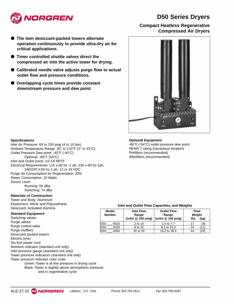
Littleton, CO USA Phone 303-794-2611 Fax 303-795-9487
D50 Series Dryers
● The twin desiccant-packed towers alternateoperation continuously to provide ultra-dry air forcritical applications.
● Timer controlled shuttle valves direct thecompressed air into the active tower for drying.
● Calibrated needle valve adjusts purge flow to actualoutlet flow and pressure conditions.
● Overlapping cycle times provide constantdownstream pressure and dew point.
Compact Heatless RegenerativeCompressed Air Dryers
SpecificationsInlet Air Pressure: 60 to 150 psig (4 to 10 bar) Ambient Temperature Range: 35° to 110°F (2° to 43°C)Outlet Pressure Dew point: -40°F (-40°C)
Optional: -66°F (54°C) Inlet and Outlet ports: 1/2-14 NPTFElectrical Requirements: 115 v-60 hz -1 ph, 230 v-60 hz-1ph,
240/220 V-50 hz-1 ph, 12 or 24 VDCPurge Air Consumption for Regeneration: 20%Power Consumption: 10 WattsSound Level:
Running: 56 dBaSwitching: 74 dBa
Materials of ConstructionTower and Body: AluminumElastomers: Nitrile and PolyurethaneDesiccant: Activated Alumina
Standard EquipmentSwitching valvesPurge valvesPurge control valvePurge mufflersDesiccant packed towersElectric timerSix-foot power cordMoisture indicator (standard unit only)Inlet pressure gauge (standard unit only)Tower pressure indicators (standard unit only)Tower pressure indicator color code:
Green: Tower is at line pressure in drying cycleBlack: Tower is slightly above atmospheric pressure
and in regenerative cycle
Optional Equipment-66°F (-54°C) outlet pressure dew pointNEMA 7 rating (hazardous location)Prefilters (recommended)Afterfilters (recommended)
ALE-27-10
Model Inlet Flow Outlet Flow TotalNumber Range Range Weight
(scfm @ 100 psig) (scfm @ 100 psig) lbs. (kg)
D50-___-0010 2 to 10 1.5 to 7.7 17 (8)D50-___-0025 8 to 25 6.1 to 19.3 24 (11)D50-___-0050 20 to 50 15.2 to 38.5 44 (20)
Inlet and Outlet Flow Capacities, and Weights

D50 Series Compact Heatless Regenerative Compressed Air Dryers
Littleton, CO USA Phone 303-794-2611 Fax 303-795-9487 ALE-27-11
A
D
C
B
F
E
IN
OUT
Moisture Indicator
Purge Adjustment
OUT
IN
H
J
G
Dryer Number* A B C D E F G H J
D50-___0010 18.50 10.00 9.00 7.06 1.25 4.90 0.44 4.62 5.25(469.90) (254.00) (228.60) (179.32) (31.75) (124.46) (11.18) (117.35) (133.35)
D50-___-0025 22.25 10.00 9.00 7.06 1.25 4.90 0.44 4.62 5.25(565.15) (254.00) (228.60) (179.32) (31.75) (124.46) (11.18) (117.35) (133.35)
D50-___-0050 27.70 10.00 9.00 7.06 1.25 4.90 0.44 4.62 5.25(703.58) (254.00) (228.60) (179.32) (31.75) (124.46) (11.18) (117.35) (133.35)
Dimensions for D50 Heatless Regenerative Compressed Air DryersInches (mm)
* For complete D50 product numbering system see ALE-27-24.
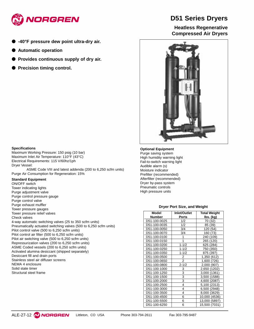
Littleton, CO USA Phone 303-794-2611 Fax 303-795-9487
D51 Series Dryers
● -40°F pressure dew point ultra-dry air.
● Automatic operation
● Provides continuous supply of dry air.
● Precision timing control.
Heatless Regenerative Compressed Air Dryers
SpecificationsMaximum Working Pressure: 150 psig (10 bar)Maximum Inlet Air Temperature: 110°F (43°C)Electrical Requirements: 115 V/60hz/1phDryer Vessel:
ASME Code VIII and latest addenda (200 to 6,250 scfm units)Purge Air Consumption for Regeneration: 15%
Standard EquipmentON/OFF switchTower indicating lightsPurge adjustment valvePurge control pressure gaugePurge control valvePurge exhaust mufflerTower pressure gaugesTower pressure relief valvesCheck valves4-way automatic switching valves (25 to 350 scfm units)Pneumatically actuated switching valves (500 to 6,250 scfm units)Pilot control valve (500 to 6,250 scfm units)Pilot control air filter (500 to 6,250 scfm units)Pilot air switching valve (500 to 6,250 scfm units)Repressurization valves (200 to 6,250 scfm units)ASME Coded vessels (200 to 6,250 scfm units)Activated alumina desiccant (shipped separately)Desiccant fill and drain portsStainless steel air diffuser screensNEMA 4 enclosureSolid state timerStructural steel frame
ALE-27-12
Model Inlet/Outlet Total WeightNumber Ports lbs. (kg)
D51-100-0025 1/2 70 (32)D51-100-0035 1/2 85 (39)D51-100-0050 3/4 120 (54)D51-100-0070 3/4 160 (73)D51-100-0100 1 240 (109)D51-100-0150 1 265 (120)D51-100-0200 1-1/2 625 (284)D51-100-0250 1-1/2 750 (350)D51-100-0350 1-1/2 875 (397)D51-100-0500 2 1,350 (612)D51-100-0650 2 1,600 (726)D51-100-0800 2-1/2 2,000 (907)D51-100-1000 3 2,650 (1202)D51-100-1250 3 3,000 (1361)D51-100-1500 3 3,500 (1588)D51-100-2000 3 4,600 (2087)D51-100-2500 4 5,100 (2313)D51-100-3000 4 6,500 (2948)D51-100-3500 4 8,000 (3629)D51-100-4500 6 10,000 (4536)D51-100-5500 6 13,000 (5897)D51-100-6250 6 15,500 (7031)
Dryer Port Size, and Weight
Optional EquipmentPurge saving systemHigh humidity warning lightFail-to-switch warning lightAudible alarm (s)Moisture indicatorPrefilter (recommended)Afterfilter (recommended)Dryer by-pass systemPneumatic controlsHigh pressure units

D51 Series Compact Heatless Regenerative Compressed Air Dryers
Littleton, CO USA Phone 303-794-2611 Fax 303-795-9487 ALE-27-13
Model 75 100 125 150Number* psig psig psig psig
D51-100-0025 20 (9) 25 (12) 30 (14) 36 (17)
D51-100-0035 27 (13) 35 (16) 43 (20) 50 (24)
D51-100-0050 39 (18) 50 (24) 61 (29) 72 (34)
D51-100-0070 55 (26) 70 (33) 85 (40) 100 (5)
D51-100-0100 78 (37) 100 (47) 122 (57) 144 (68)
D51-100-0150 117 (55) 150 (71) 183 (86) 215 (101)
D51-100-0200 156 (73) 200 (94) 244 (115) 287 (135)
D51-100-0250 196 (92) 250 (118) 304 (143) 359 (169)
D51-100-0350 274 (129) 350 (165) 426 (200) 503 (236)
D51-100-0500 391 (184) 500 (235) 609 (286) 718 (337)
D51-100-0650 508 (239) 650 (306) 792 (372) 933 (439)
D51-100-0800 626 (294) 800 (376) 974 (458) 1,149 (540)
D51-10-1000 782 (368) 1,000 (470) 1,218 (572) 1,436 (675)
D51-100-1250 978 (460) 1,250 (588) 1,522 (715) 1,795 (844)
D51-100-1500 1,173 (551) 1,500 (705) 1,827 (859) 2,154 (1012)
D51-100-2000 1,564 (735) 2,000 (940) 2,436 (1145) 2,872 (1350)
D51-100-2500 1,955 (919) 2,500 (1175) 3,045 (1431) 3,590 (1687)
D51-100-3000 2,346 (1103) 3,000 (1410) 3,654 (1717) 4,308 (2025)
D51-100-3500 2,740 (1288) 3,500 (1645) 4,265 (2005) 5,025 (2362)
D51-100-4500 3,520 (1654) 4,500 (2115) 5,480 (2576) 6,460 (3036)
D51-100-5500 4,300 (2021) 5,500 (2585) 6,700 (3149) 7,900 (3713)
D51-100-6250 4,885 (2296) 6,250 (2938) 7,610 (3577) 8,980 (4221)
Flow Capacity Selection Chart[scfm (dm3/s) @ -40°F (-40°C) Pressure Dew Point and
100°F (38°C) Ambient Temperature]
* For complete D51 product numbering system see ALE-27-25.
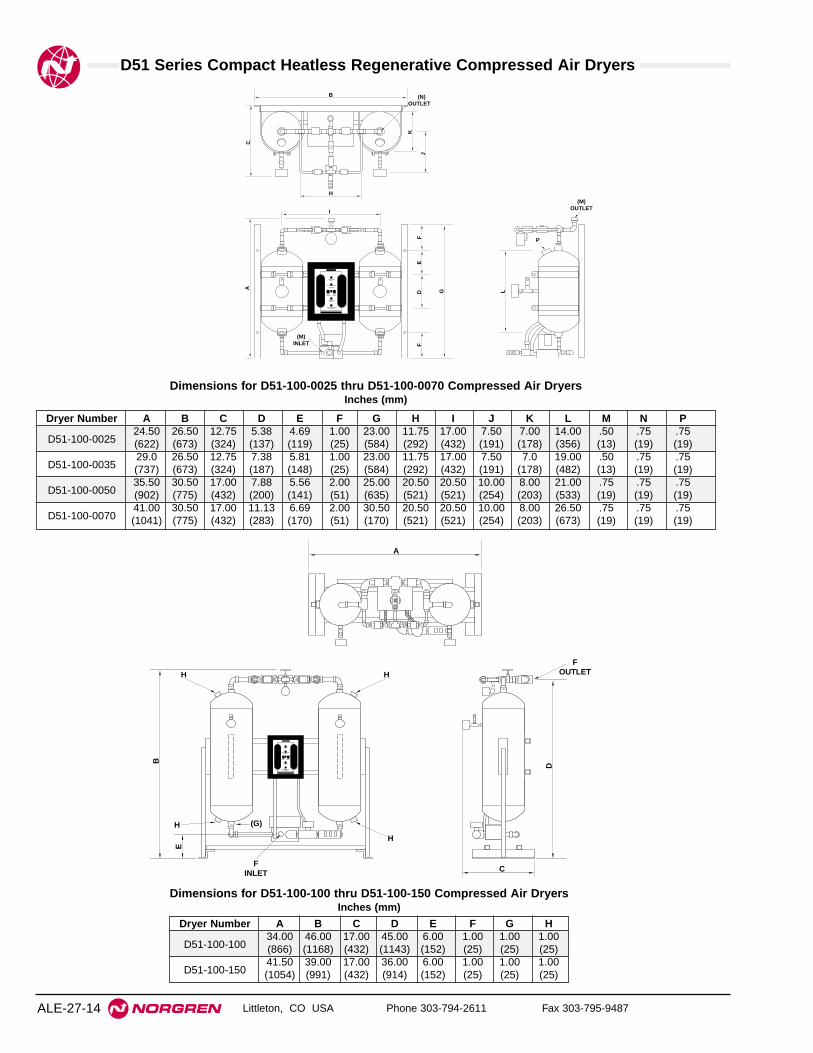
D51 Series Compact Heatless Regenerative Compressed Air Dryers
Littleton, CO USA Phone 303-794-2611 Fax 303-795-9487ALE-27-14
Dryer Number A B C D E F G H I J K L M N P
D51-100-002524.50 26.50 12.75 5.38 4.69 1.00 23.00 11.75 17.00 7.50 7.00 14.00 .50 .75 .75(622) (673) (324) (137) (119) (25) (584) (292) (432) (191) (178) (356) (13) (19) (19)
D51-100-003529.0 26.50 12.75 7.38 5.81 1.00 23.00 11.75 17.00 7.50 7.0 19.00 .50 .75 .75(737) (673) (324) (187) (148) (25) (584) (292) (432) (191) (178) (482) (13) (19) (19)
D51-100-005035.50 30.50 17.00 7.88 5.56 2.00 25.00 20.50 20.50 10.00 8.00 21.00 .75 .75 .75(902) (775) (432) (200) (141) (51) (635) (521) (521) (254) (203) (533) (19) (19) (19)
D51-100-007041.00 30.50 17.00 11.13 6.69 2.00 30.50 20.50 20.50 10.00 8.00 26.50 .75 .75 .75(1041) (775) (432) (283) (170) (51) (170) (521) (521) (254) (203) (673) (19) (19) (19)
Dimensions for D51-100-0025 thru D51-100-0070 Compressed Air DryersInches (mm)
K
J
C
B
H
A G
FF
E
LD
I
(M)INLET
P
(M)OUTLET
(N)OUTLET
A
B
D
H
FINLET
H H
H
C
E
(G)
FOUTLET
Dryer Number A B C D E F G H
D51-100-10034.00 46.00 17.00 45.00 6.00 1.00 1.00 1.00(866) (1168) (432) (1143) (152) (25) (25) (25)
D51-100-15041.50 39.00 17.00 36.00 6.00 1.00 1.00 1.00(1054) (991) (432) (914) (152) (25) (25) (25)
Dimensions for D51-100-100 thru D51-100-150 Compressed Air DryersInches (mm)

D51 Series Compact Heatless Regenerative Compressed Air Dryers
Littleton, CO USA Phone 303-794-2611 Fax 303-795-9487 ALE-27-15
Dryer Number A B C D E
D51-100-20065.00 34.00 35.00 61.00 1.50(1651) (1156) (889) (1549) (38)
D51-100-25079.00 34.00 35.00 75.00 1.50(2007) (1156) (889) (1905) (38)
D51-100-35065.00 38.00 35.00 62.00 1.50(1651) (965) (889) (1575) (38)
D51-100-50095.00 38.00 27.00 91.00 2.00(2413) (965) (686) (2311) (51)
D51-100-65094.00 42.00 29.00 90.00 2.00(2388) (1067) (7366) (2286) (51)
D
A
B C
24"
EINLET
EOUTLET
7-1/
2 "
Dimensions for D51-100-200 thru D51-100-650Compressed Air Dryers
Inches (mm)
14"
B
D
A C
FINLET
FOUTLET
Dryer Number A B C D E F
D51-100-0800 51.00 100.00 40.00 96.00 2.50 2.5(1295) (2540) (1016) (2438) (64) (64)
D51-100-1000 54.50 102.00 40.00 98.00 3.00 3.00(1384) (2591) (1016) (2489) (76) (76)
D51-100-1250 68.00 109.00 40.00 105.00 3.00 3.00(1727) (2769) (1016) (2667) (76) (76)
D51-100-1500 72.00 94.00 42.00 89.00 3.00 3.00(1829) (2388) (1067) (2261) (76) (76)
D51-100-2000 66.00 111.00 42.00 107.00 3.00 3.00(1676) (2819) (1067) (2718) (76) (76)
D51-100-2500 78.00 116.00 55.00 111.00 4.00 4.00(1981) (2946) (1397) (2819) (102) (102)
D51-100-3000 99.00 113.00 57.50 108.00 4.00 4.00(2515) (2870) (1461) (2743) (102) (102)
D51-100-3500 99.00 117.00 58.00 112.00 4.00 4.00(2515) (2972) (1473) (2845) (102) (102)
D51-100-4500 105.00 136.00 58.00 130.00 6.00 6.00(2667) (3454) (1473) (3302) (152) (152)
D51-100-5500 105.00 125.00 58.00 119.00 6.00 6.00(2667) (3175) (1473) (3023) (152) (152)
D51-100-6250 116.00 138.00 58.00 132.00 6.00 6.00(2946) (3505) (1473) (3353) (152) (152)
Dimensions for D51-100-0800 thru D51-100-6250 Compressed Air Dryers
Inches (mm)
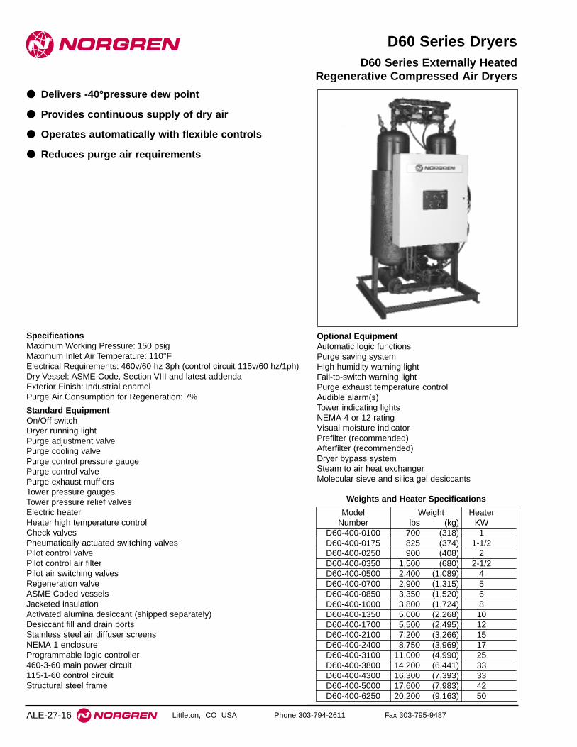
Littleton, CO USA Phone 303-794-2611 Fax 303-795-9487
D60 Series Dryers
● Delivers -40°pressure dew point
● Provides continuous supply of dry air
● Operates automatically with flexible controls
● Reduces purge air requirements
D60 Series Externally HeatedRegenerative Compressed Air Dryers
SpecificationsMaximum Working Pressure: 150 psigMaximum Inlet Air Temperature: 110°FElectrical Requirements: 460v/60 hz 3ph (control circuit 115v/60 hz/1ph)Dry Vessel: ASME Code, Section VIII and latest addendaExterior Finish: Industrial enamelPurge Air Consumption for Regeneration: 7%
Standard EquipmentOn/Off switchDryer running lightPurge adjustment valvePurge cooling valvePurge control pressure gaugePurge control valvePurge exhaust mufflersTower pressure gaugesTower pressure relief valvesElectric heaterHeater high temperature controlCheck valvesPneumatically actuated switching valvesPilot control valvePilot control air filterPilot air switching valvesRegeneration valveASME Coded vesselsJacketed insulationActivated alumina desiccant (shipped separately)Desiccant fill and drain portsStainless steel air diffuser screensNEMA 1 enclosureProgrammable logic controller460-3-60 main power circuit115-1-60 control circuitStructural steel frame
ALE-27-16
Optional EquipmentAutomatic logic functionsPurge saving systemHigh humidity warning lightFail-to-switch warning lightPurge exhaust temperature controlAudible alarm(s)Tower indicating lightsNEMA 4 or 12 ratingVisual moisture indicatorPrefilter (recommended)Afterfilter (recommended)Dryer bypass systemSteam to air heat exchangerMolecular sieve and silica gel desiccants
Model Weight HeaterNumber lbs (kg) KW
D60-400-0100 700 (318) 1D60-400-0175 825 (374) 1-1/2D60-400-0250 900 (408) 2D60-400-0350 1,500 (680) 2-1/2D60-400-0500 2,400 (1,089) 4D60-400-0700 2,900 (1,315) 5D60-400-0850 3,350 (1,520) 6D60-400-1000 3,800 (1,724) 8D60-400-1350 5,000 (2,268) 10D60-400-1700 5,500 (2,495) 12D60-400-2100 7,200 (3,266) 15D60-400-2400 8,750 (3,969) 17D60-400-3100 11,000 (4,990) 25D60-400-3800 14,200 (6,441) 33D60-400-4300 16,300 (7,393) 33D60-400-5000 17,600 (7,983) 42D60-400-6250 20,200 (9,163) 50
Weights and Heater Specifications

D60 Series Externally Heated Regenerative Compressed Air Dryers
Littleton, CO USA Phone 303-794-2611 Fax 303-795-9487 ALE-27-17
Model 75 100 125 150Number* psig psig psig psig
D60-400-0100 78 100 122 144(37) (47) (57) (68)
D60-400-0175 137 175 213 252(64) (82) (100) (85)
D60-400-0250 196 250 304 359(92) (118) (143) (169)
D60-400-0350 274 350 426 503(129) (165) (200) (236)
D60-400-0500 391 500 609 718(184) (235) (286) (337)
D60-400-0700 547 700 853 1,005(257) (329) (401) (472)
D60-400-0850 665 850 1,035 1,220(313) (400) (486) (573)
D60-400-1000 782 1,000 1,218 1,436(368) (470) (572) (675)
D60-400-1350 1,056 1,350 1,644 1,938(496) (635) (773) (911)
D60-400-1700 1,329 1,700 2,071 2,441(625) (799) (973) (1147)
D60-400-2100 1,642 2,100 2,558 3,016(772) (987) (1202) (1418)
D60-400-2400 1,877 2,400 2,923 3,446(882) (1128) (1374) (1620)
D60-400-3100 2,424 3,100 3,776 4,451(1139) (1457) (1775) (2092)
D60-400-3800 2,972 3,800 4,628 5,456(1397) (1786) (2175) (2564)
D60-400-4300 3,363 4,300 5,237 6,175(1581) (2021) (2461) (2902)
D60-400-5000 3,910 5,000 6,090 7,180(1838) (2350) (2862) (3375)
D60-400-6250 4,888 6,250 7,612 8,975(2297) (2938) (3578) (4218)
Flow Capacity Selection Chart[scfm (dm3/s) @ 100°F (38°C) inlet temperature and
-40°F (-40°C) pressure dew point]
* For complete D60 product numbering system see ALE-27-26.
D
CB
A E
FOUTLET
FINLET
Dryer Number A B C D E F
D60-400-0100 36.00 77.50 68.00 6.00 34.00 1.00(914) (1969) (1727) (152) (864) (25)
D60-400-0175 40.00 82.00 72.00 7.00 38.00 1.50(1016) (2083) (1829) (178) (965) (38)
D60-400-0250 42.00 71.00 61.00 7.00 43.00 1.50(1067) (1803) (1549) (178) (1092) (38)
D60-400-0350 42.00 86.00 85.00 7.00 43.00 1.50(1067) (2184) (2159) (178) (1092) (38)
D60-400-0500 50.00 97.00 95.00 10.00 44.00 2.00(1270) (2464) (2413) (254) (1118) (51)
Dimensions for D60-400-0100 thru D60-400-0500 Externally HeatedRegenerative Compressed Air Dryers
inches (mm)
D12
B
A C
FOUTLET
EINLET NOTE: HEATER MAY
BE HORIZONTAL
Dryer Number A B C D E F
D60-400-700 44.00 109.00 48.00 105.00 2.00 2.00(1118) (2769) (1219) (2667) (51) (51)
D60-400-850 50.00 111.00 50.00 106.00 2.50 2.50(1270) (2819) (1270) (2692) (64) (64)
D60-400-1000 71.00 93.00 61.00 89.00 3.00 3.00(1803) (2362) (1549) (2261) (76) (76)
D60-400-1350 71.00 110.00 61.00 106.00 3.00 3.00(1803) (2794) (1549) (2692) (76) (76)
D60-400-1700 78.00 100.00 61.00 96.00 3.00 3.00(1981) (2540) (1549) (2438) (76) (76)
D60-400-2100 95.00 97.50 70.00 93.50 3.00 3.00(2413) (2477) (1778) (2375) (76) (76)
D60-400-2400 99.00 114.00 67.00 109.00 4.00 4.00(2515) (2896) (1702) (2769) (102) (102)
D60-400-3100 105.00 112.00 67.00 107.00 4.00 4.00(2667) (2845) (1702) (2718) (102) (102)
D60-400-3800 105.00 120.00 67.00 115.00 4.00 4.00(2667) (3048) (1702) (2921) (102) (102)
D60-400-4300 116.00 120.00 85.00 114.00 6.00 6.00(2946) (3048) (2159) (2896) (152) (152)
D60-400-5000 116.00 127.00 85.00 121.00 6.00 6.00(2946) (3226) (2159) (3073) (152) (152)
D60-400-5500 122.00 113.00 85.00 107.00 6.00 6.00(3099) (2870) (2159) (2718) (152) (152)
D60-400-6250 122.00 121.00 85.00 115.00 6.00 6.00(3099) (3073) (2159) (2921) (152) (152)
Dimensions for D60-400-0700 thru D60-400-6250 Externally HeatedRegenerative Compressed Air Dryers
inches (mm)

Littleton, CO USA Phone 303-794-2611 Fax 303-795-9487
D70 Series Dryers
● Delivers -40°pressure dew point
● Provides continuous supply of dry air
● Operates automatically with flexible controls
● Reduces purge air requirements
D70 Series Blower PurgeRegenerative Compressed Air Dryers
SpecificationsMaximum Working Pressure: 150 psigMaximum Inlet Air Temperature: 110°FElectrical Requirements: 460v/60 hz 3ph (control circuit 115v/60 hz/1ph)Dry Vessel: ASME Code, Section VIII and latest addendaExterior Finish: Industrial enamelPurge Air Consumption for Regeneration: Less than 5%Standard EquipmentOn/Off switchDryer running lightPurge adjustment valvePurge cooling valvePurge control pressure gaugePurge control valvePurge exhaust mufflersTower pressure gaugesTower pressure relief valvesBlowerBlower intake filterElectric heaterHeater high temperature controlCheck valvesPneumatically actuated switching valvesPilot control valvePilot control air filterPilot air switching valvesRegeneration valveASME Coded vesselsJacketed insulationActivated alumina desiccant (shipped separately)Desiccant fill and drain portsStainless steel air diffuser screensNEMA 1 enclosureProgrammable logic controller460-3-60 main power circuit115-1-60 control circuitStructural steel frame
ALE-27-18
Optional EquipmentAutomatic logic functionsPurge saving systemHigh humidity warning lightFail-to-switch warning lightPurge exhaust temperature controlAudible alarm(s)Tower indicating lightsNEMA 4 or 12 ratingVisual moisture indicatorPrefilter (recommended)Afterfilter (recommended)Dryer bypass systemSteam to air heat exchangerMolecular sieve and silica gel desiccants
Model Weight Blower HeaterNumber lbs. (kg) HP KW
D70-400-0250 1,200 (544) 3 4D70-400-0350 1,500 (680) 3 5D70-400-0500 2,400 (1,089) 5 8D70-400-0700 2,900 (1,315) 5 10D70-400-1000 3,800 (1,724) 10 12D70-400-1350 5,000 (2,268) 10 17D70-400-1700 5,500 (5,495) 15 25D70-400-2400 8,750 (3,969) 15 33D70-400-3100 11,000 (4,990) 15 42D70-400-3800 14,200 (6,441) 20 50D70-400-4300 16,300 (7,394) 20 58D70-400-5000 17,700 (8,029) 25 67D70-400-6250 20,200 (9,163) 30 87
Weights and Heater Specifications
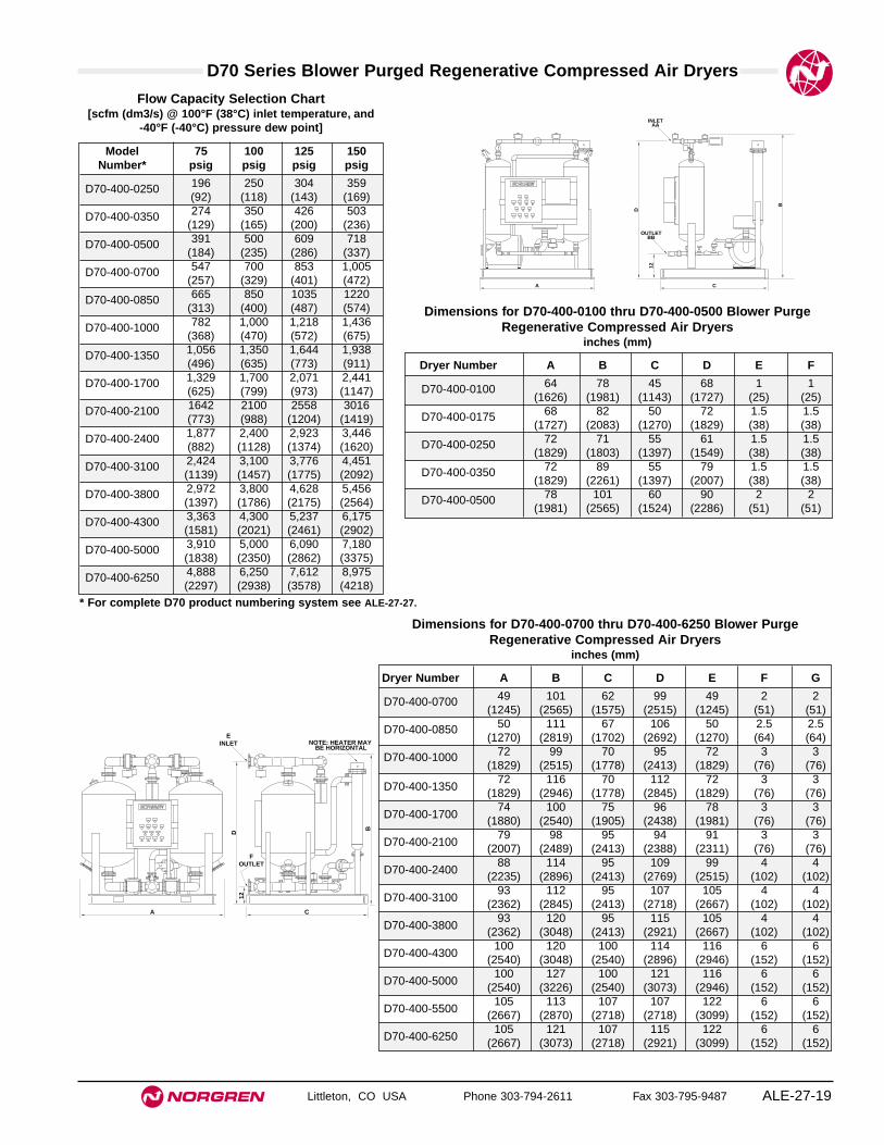
D70 Series Blower Purged Regenerative Compressed Air Dryers
Littleton, CO USA Phone 303-794-2611 Fax 303-795-9487 ALE-27-19
Model 75 100 125 150Number* psig psig psig psig
D70-400-0250 196 250 304 359(92) (118) (143) (169)
D70-400-0350 274 350 426 503(129) (165) (200) (236)
D70-400-0500 391 500 609 718(184) (235) (286) (337)
D70-400-0700 547 700 853 1,005(257) (329) (401) (472)
D70-400-0850 665 850 1035 1220(313) (400) (487) (574)
D70-400-1000 782 1,000 1,218 1,436(368) (470) (572) (675)
D70-400-1350 1,056 1,350 1,644 1,938(496) (635) (773) (911)
D70-400-1700 1,329 1,700 2,071 2,441(625) (799) (973) (1147)
D70-400-2100 1642 2100 2558 3016(773) (988) (1204) (1419)
D70-400-2400 1,877 2,400 2,923 3,446(882) (1128) (1374) (1620)
D70-400-3100 2,424 3,100 3,776 4,451(1139) (1457) (1775) (2092)
D70-400-3800 2,972 3,800 4,628 5,456(1397) (1786) (2175) (2564)
D70-400-4300 3,363 4,300 5,237 6,175(1581) (2021) (2461) (2902)
D70-400-5000 3,910 5,000 6,090 7,180(1838) (2350) (2862) (3375)
D70-400-6250 4,888 6,250 7,612 8,975(2297) (2938) (3578) (4218)
Flow Capacity Selection Chart[scfm (dm3/s) @ 100°F (38°C) inlet temperature, and
-40°F (-40°C) pressure dew point]
* For complete D70 product numbering system see ALE-27-27.
D
12
B
A C
OUTLETBB
INLETAA
Dryer Number A B C D E F
D70-400-0100 64 78 45 68 1 1(1626) (1981) (1143) (1727) (25) (25)
D70-400-0175 68 82 50 72 1.5 1.5(1727) (2083) (1270) (1829) (38) (38)
D70-400-0250 72 71 55 61 1.5 1.5(1829) (1803) (1397) (1549) (38) (38)
D70-400-0350 72 89 55 79 1.5 1.5(1829) (2261) (1397) (2007) (38) (38)
D70-400-0500 78 101 60 90 2 2(1981) (2565) (1524) (2286) (51) (51)
Dimensions for D70-400-0100 thru D70-400-0500 Blower PurgeRegenerative Compressed Air Dryers
inches (mm)
D12
B
A C
FOUTLET
EINLET NOTE: HEATER MAY
BE HORIZONTAL
Dryer Number A B C D E F G
D70-400-0700 49 101 62 99 49 2 2(1245) (2565) (1575) (2515) (1245) (51) (51)
D70-400-0850 50 111 67 106 50 2.5 2.5(1270) (2819) (1702) (2692) (1270) (64) (64)
D70-400-1000 72 99 70 95 72 3 3(1829) (2515) (1778) (2413) (1829) (76) (76)
D70-400-135072 116 70 112 72 3 3
(1829) (2946) (1778) (2845) (1829) (76) (76)
D70-400-170074 100 75 96 78 3 3
(1880) (2540) (1905) (2438) (1981) (76) (76)
D70-400-210079 98 95 94 91 3 3
(2007) (2489) (2413) (2388) (2311) (76) (76)
D70-400-240088 114 95 109 99 4 4
(2235) (2896) (2413) (2769) (2515) (102) (102)
D70-400-310093 112 95 107 105 4 4
(2362) (2845) (2413) (2718) (2667) (102) (102)
D70-400-380093 120 95 115 105 4 4
(2362) (3048) (2413) (2921) (2667) (102) (102)
D70-400-4300100 120 100 114 116 6 6
(2540) (3048) (2540) (2896) (2946) (152) (152)
D70-400-5000100 127 100 121 116 6 6
(2540) (3226) (2540) (3073) (2946) (152) (152)
D70-400-5500105 113 107 107 122 6 6
(2667) (2870) (2718) (2718) (3099) (152) (152)
D70-400-6250105 121 107 115 122 6 6
(2667) (3073) (2718) (2921) (3099) (152) (152)
Dimensions for D70-400-0700 thru D70-400-6250 Blower PurgeRegenerative Compressed Air Dryers
inches (mm)

Littleton, CO USA Phone 303-794-2611 Fax 303-795-9487
W74D
● Excelon Quikclamp™ design provides in-line ormodular installation with 72, 73 and 74 Seriesproducts.
● Helps eliminate condensate at point-of-use.
● Replaceable element filters outlet air to help preventdesiccant dust migration down stream.
● Desiccant color changes from blue to pink whendesiccant replacement is needed.
● Transparent or metal bowl available. On models withmetal bowl, moisture indicator on top of bodyindicates condition of desiccant.
● Desiccant can be dried and reused or replaced withnew packet.
● Typical dew point supression of 15°F (-10°C) belowinlet ambient pressure dew point.
Excelon 74 Desiccant Compressed Air Dryer1/4", 3/8", and 1/2" Port Sizes
ALE-27-20
Ordering Information. Models listed include PTF threads and a closed bottom bowl.
Port Size Bowl Model Weight lb (kg)3/8" Transparent, 7 fluid ounce (0.2 liter) W74D-3AN-NPN 2.00 (0.91)1/2" Transparent, 7 fluid ounce (0.2 liter) W74D-4AN-NPN 2.00 (0.91)1/2" Metal, 1 quart (1 liter) W74D-4AN-NMN 4.25 (1.93)
Alternative Models
W 7 4 -D ★ ★ - ★★ ★ ★
Threads SubstitutePTF AISO Rc taper BISO G parallel G
Drain SubstituteClosed bottom (no drain) N
Flow SubstituteNot applicable N
Port Size Substitute1/4" 23/8" 31/2" 4
Bowl Substitute1 quart (1 liter) metal M7 fluid ounce (0.2 liter) Ptransparent with guard
Moisture Indicator * SubstituteNo indicator NWith indicator D
* Moisture indicator used only with dryers equipped with metal bowl.
ISO Symbols

Excelon 74 Desiccant Compressed Air Dryer
Littleton, CO USA Phone 303-794-2611 Fax 303-795-9487 ALE-27-21
All Dimensions in Inches (mm)
Technical DataFluid: Compressed airMaximum pressure
Transparent bowl: 150 psig (10 bar)Metal bowl: 250 psig (17 bar)
Operating temperature*Transparent bowl: 0° to 125°F (-20° to 50°C)Metal bowl: 0° to 175°F (-20° to 80°C)
* Air supply must be dry enough to avoid ice formation at temperatures below 35°F( 2°C).Nominal bowl capacity
Transparent: 0.25 pounds (0.11 kg) desiccantMetal: 1.25 pounds (0.57 kg) desiccant
Nominal air drying capacity at 100 psig (6.9 bar) inlet pressure and 77°F (25°C)Transparent bowl: 750 cubic feet (21 cubic meters)Metal bowl: 6000 cubic feet (170 cubic meters)
Required prefilters: General purpose filter with 5-micron element and an oilremoval filter with equivalent pipe size and flow capacity equal to or greaterthan the desiccant dryer.
Desiccant regeneration: Desiccant can be dried and reused by removing fromdryer and heating to 275°F (135°C). Regeneration is complete whendesiccant returns to original blue color.
Moisture indicator leakage on models with metal bowl: Air continuously passes thruthe moisture indicator and escapes to atmosphere. This is normal and doesnot indicate a faulty indicator.
MaterialsBody: AluminumBowl
Transparent: Polycarbonate with steel bowl guardMetal: Aluminum
Supply tube assembly: Aluminum/stainless steel screenDesiccant drying agent: Silica gelFilter element: Sintered polypropyleneElastomers: Neoprene and NitrileMoisture indicator materials - used only with 1 quart (1 liter) metal bowl
Body: Transparent nylonTest paper: Cobalt chlorideElastomers: Nitrile
Service KitsItem Type Part NumberService kit Seal and filter element 4385-710Desiccant 5 bags desiccant, 0.25 lb 4385-700
(0.11 kg) in each bag
4.32 (110)
3.15 (80)
11.1
4 (2
83)
1.00
(25
)
2.36
(60
)
20.0
0 (5
08)
*
2.89
(74
)
1.00
(25
)
1.45
(37
) 3.15 (80)
6.18
(15
7) C
lose
d B
ott
om
10.8
7 (2
76)
*
* Minimum clearance required to remove bowl.
7 fluid ounce (0.2 liter) bowl
1 quart (1 liter) bowl

Littleton, CO USA Phone 303-794-2611 Fax 303-795-9487
F21 / F61
● High flow mainline system filters
● The F21 provides 1 micron particle removal filtration
● The F61 provides 0.01 oil coalescing
● The F61 features carbon type vapor removal filtration
● Optional automatic or timer drains available
F21and F61 Mainline Filters
Technical DataMaximum Working Pressure: 150 psig (10 bar)Maximum Inlet Temperature: 150°F (65°C)Dryer Vessel: ASME Code, Section VIII, and latest addenda (4" and
larger units)Exterior Finish: Industrial enamelStandard: Manual drain valve, and pressure differential gauge.
ALE-27-22
Model A B C D E F G H J AA BB CC DD Wt.
F21/F61-F0145.13 17.63 36.50 3.50 4.50 6.00 5.50 8.63 41.00 3.00 0.50 0.25 3.00
175(1146) (448) (927) (89) (114) (152) (140) (219) (1041) (76) (13) (6) (76)
F21/F61-G0144.38 21.75 34.88 4.00 4.50 6.38 5.50 12.75 37.00 4.00 0.50 0.25 4.00
300(1127) (552) (886) (102) (114) (162) (140) (324) (940) (102) (13) (6) (102)
F21/F61-J0156.25 23.75 45.75 5.00 5.50 6.50 7.00 12.75 51.00 6.00 0.50 0.25 4.00
350(1429) (603) (1162) (127) (140) (165) (178) (324) (1295) (152) (13) (6) (102)
F21/F61-01Inches (mm)
C
H
BB Drain Port
J
D
B
5/16" Plate
CC CC AA
AA
A FilterCoupling
E EF G
DD
FilterCoupling
DD

F21 and F61 Mainline Filters
Littleton, CO USA Phone 303-794-2611 Fax 303-795-9487 ALE-27-23
All Dimensions in Inches (mm)
* For complete F21 and F61 product numbering system see ALE-27-30
Model A B C D E AA BB CC Wt.
F21/F61-J5175.00 55.56 12.63 16.00 22.00 6.00 0.50
6 x 8 415(1905) (1411) (321) (406) (559) (152) (13)
F21/F61-L5181.00 60.31 12.06 20.00 27.13 8.00 0.50
11x15 670(2057) (1532) (306) (508) (689) (203) (13)
F21/F61-51Inches (mm)
8 (203)
6 (152)
37.5(952)
7 (178)
2.5 (64)
1/8" NPT
Port 23" FPT
Port 13" FPT
ECC
AAPort 1(Inlet for Coalescers)
1/4" Connection for Differential Pressure Gauge
1/4" Connection for Differential Pressure Gauge
A
B
C
36"
AA Port 2(Inlet for
Interceptors and
Adsobers)
Clearance for Removal of 28" Elements
BB(DrainOutlet)
H
Filter Connections
F21/F61-E01

D11 Series Product Numbering System
Littleton, CO USA Phone 303-794-2611 Fax 303-795-9487ALE-27-24
Unit
Series
Voltage
Accessory Package
Cabinet Options
D = Compressed Air Dryer
11 Series = Refrigerated, R134a
1 = 115-60 Hz-1/110-50 Hz-1 (5 thru 150 scfm units)2 = 230/220-60 Hz-1/200-50 Hz-1 (5 & 10, 40 thru 200 scfm units)3 = 230/208-60 Hz-3 (200 scfm only)4 = 460-60 Hz-3 (200 scfm only)6 = 240/220-50 Hz-1 (5 thru 200 scfm units)
0 = (5 thru 100 scfm units)16'' power cord
(130 thru 200 scfm units)On/Off switch, power on and high temperature indicator lights, drain tube, panelmounted refrigerant suction pressure gauge, and electrical terminal block
1 = (5 thru 20 scfm units)Panel mounted refrigerant suction pressure gauge, drain tube kit and 16'' powercord
2 = (5 thru 100 scfm units)Panel mounted refrigerant suction pressure gauge, 6’ power cord, on/off switch,power on and high temperature indicator lights and drain tube kit
3 = (30 thru 100 scfm units)Panel mounted refrigerant suction pressure gauge, 6’ power cord, on/off switch,power on and high temperature indicator lights, outlet air pressure gauge, inlet airtemperature gauge, and drain tube kit
(130 thru 200 scfm units)Panel mounted refrigerant suction pressure gauge, electrical terminal block, on/offswitch, power on and high temperature indicator lights, outlet air pressure gauge,inlet air temperature gauge and drain tube kit
4 = (130 thru 200 scfm units)Panel mounted refrigerant suction pressure gauge, refrigerant discharge pressuregauge, electrical terminal block, on/off switch, power on and high temperatureindicator lights, outlet air pressure gauge, inlet air temperature gauge, outlet airtemperature gauge, inlet air pressure gauge and drain tube kit
Position
Sample Model Number
1
2 3
4
5
60 = No side panels1 = Side panels2 = Ambient filter with no side panels3 = Ambient filter with side panels
0005 = 5 scfm0010 = 10 scfm0015 = 15 scfm0020 = 20 scfm0030 = 30 scfm0040 = 40 scfm0050 = 50 scfm0075 = 75 scfm0100 = 100 scfm0130 = 130 scfm0150 = 150 scfm0200 = 200 scfm
7 8 Size9 10
D 1 1 - 1 0 0 - 0 0 1 0
1 2 3 - 4 5 6 - 7 8 9 10

D10 Series Product Numbering System
Littleton, CO USA Phone 303-794-2611 Fax 303-795-9487 ALE-27-25
Unit
Series
Voltage
Accessory Package
Options
D = Compressed Air Dryer
10 Series = Refrigerated, R22
2 = 230/208-60 Hz-13 = 230/208-60 Hz-34 = 460-60 Hz-35 = 600/550-60 Hz-36 = 240/220-50 Hz-17 = 240/220-50 Hz-38 = 420/380-50 Hz-3
0 = (250 thru 500 scfm units)On/Off switch (control circuit), power on light, refrigerant suction pressure gauge,air inlet temperature gauge and air outlet pressure gauge
(600 scfm and larger units)On/off switch (control circuit), power on light, refrigerant suction pressure gauge,refrigerant discharge pressure gauge, air inlet and outlet temperature gauges, andair inlet and outlet pressure gauges
1 = (250 thru 500 scfm units)On/off switch (control circuit),power on light, refrigerant suction pressure gauge,refrigerant discharge pressure gauge, air inlet and outlet pressure gauges, and airinlet and outlet temperature gauges
2 = On/off switch (control circuit),power on light, refrigerant suction pressure gauge,refrigerant discharge pressure gauge, air inlet and outlet pressure gauges, air inletand outlet temperature gauges, and alarm bell
3 = On/off switch (control circuit),power on light, refrigerant suction pressure gauge,refrigerant discharge pressure gauge, air inlet and outlet pressure gauges, and airinlet and outlet temperature gauges,and flow meter
4 = On/off switch (control circuit),power on light, refrigerant suction pressure gauge,refrigerant discharge pressure gauge, air inlet and outlet pressure gauges, air inletand outlet temperature gauges, alarm bell and flow meter
Position
Sample Model Number
1
2 3
4
5
60 = Air-cooled1 = Water-cooled2 = Air-cooled with ambient filters
0250 = 250 scfm0325 = 325 scfm0400 = 400 scfm0500 = 500 scfm0600 = 600 scfm0800 = 800 scfm1000 = 1000 scfm1250 = 1250 scfm1500 = 1500 scfm*1750 = 1750 scfm2000 = 2000 scfm2500 = 2500 scfm3200 = 3200 scfm4000 = 4000 scfm5000 = 5000 scfm6250 = 6250 scfm7500 = 7500 scfm
7 8 Size9 10
D 1 0 - 2 0 0 - 0 2 5 0
1 2 3 - 4 5 6 - 7 8 9 10
* Not available as a water-cooled unit

D50 Series Product Numbering System
Littleton, CO USA Phone 303-794-2611 Fax 303-795-9487ALE-27-26
Unit
Series
Voltage
Model
Options
D = Compressed Air Dryer
50 Series = Compact Heatless Regenerative
1 = 115-60 Hz2 = 230-60 Hz6 = 240/220-50 Hz-1A = 12VDCB = 24VDC
0 = Standard Model5 = Economy Model
Position
Sample Model Number
1
2 3
4
5
61 = -66°F Dew point (standard unit only)4 = Hazardous location, -40°F Dew point (standard unit only)5 = Hazardous location, -66°F Dew point (standard unit only)
0010 = 10 scfm0025 = 25 scfm0050 = 50 scfm
7 8 Size9 10
D 5 0 - 1 0 0 - 0 0 5 0
1 2 3 - 4 5 6 - 7 8 9 10

D51 Series Product Numbering System
Littleton, CO USA Phone 303-794-2611 Fax 303-795-9487 ALE-27-27
Unit
Series
Voltage
Model
Options
D = Compressed Air Dryer
51 Series = Heatless Regenerative
1 = 115-60 Hz-1
0 = Instrumentation Model
Position
Sample Model Number
1
2 3
4
5
6
0 = No options1 = Visual moisture indicator2 = Fail-to-switch warning light3 = Purge saving system4 = Purge saving system and fail to switch warning light5 = Purge saving system with high humidity warning light6 = Purge saving system with high humidity warning light,
fail-to-switch warning light7 = Visual moisture indicator and fail-to-switch warning light8 = Purge saving system with high humidity warning light,
visual moisture indicator, and fail-to-switch warning light
7 8 Size9 10
D 5 1 - 1 0 0 - 0 0 5 0
1 2 3 - 4 5 6 - 7 8 9 10
0025 = 25 scfm0035 = 35 scfm0050 = 50 scfm0070 = 70 scfm0100 = 100 scfm0150 = 150 scfm0200 = 200 scfm0250 = 250 scfm0350 = 350 scfm0500 = 500 scfm0650 = 650 scfm0800 = 800 scfm1000 = 1,000 scfm1250 = 1,250 scfm1500 = 1,500 scfm2000 = 2,000 scfm2500 = 2,500 sfcm3000 = 3,000 scfm3500 = 3,500 scfm4500 = 4,500 scfm5500 = 5,500 scfm6250 - 6,250 scfm

D60 Series Product Numbering System
Littleton, CO USA Phone 303-794-2611 Fax 303-795-9487ALE-27-28
Unit
Series
Voltage
Model
Options
D = Compressed Air Dryer
60 Series = Externally Heated Regenerative
4 = 460-60 Hz-3/(control circuit 115-60 Hz-1)
0 = Standard Model
Position
Sample Model Number
1
2 3
4
5
6
0 = No options1 = Visual moisture indicator2 = Fail-to-switch warning light3 = Purge saving system4 = Purge saving system and fail to switch warning light
7 8 Size9 10
D 6 0 - 4 0 0 - 1 0 0 0
1 2 3 - 4 5 6 - 7 8 9 10
0100 = 100 scfm0175 = 175 scfm0250 = 250 scfm0350 = 350 scfm0500 = 500 scfm0700 = 700 scfm0850 = 850 scfm1000 = 1,000 scfm1350 = 1,350 scfm1700 = 1,700 scfm2100 = 2,100 scfm2400 = 2,400 sfcm3100 = 3,100 scfm3800 = 3,800 scfm4300 = 4,300 scfm5000 = 5,000 scfm6250 - 6,250 scfm

D70 Series Product Numbering System
Littleton, CO USA Phone 303-794-2611 Fax 303-795-9487 ALE-27-29
Unit
Series
Voltage
Model
Options
D = Compressed Air Dryer
70 Series = Blower Purge Regenerative
4 = 460-60 Hz-3/(control circuit 115-60 Hz-1)
0 = Standard Model
Position
Sample Model Number
1
2 3
4
5
6
0 = No options1 = Visual moisture indicator2 = Fail-to-switch warning light3 = Purge saving system4 = Purge saving system and fail to switch warning light
7 8 Size9 10
D 7 0 - 4 0 0 - 1 0 0 0
1 2 3 - 4 5 6 - 7 8 9 10
0250 = 250 scfm0350 = 350 scfm0500 = 500 scfm0700 = 700 scfm0850 = 850 scfm1000 = 1,000 scfm1350 = 1,350 scfm1700 = 1,700 scfm2100 = 2100 scfm2400 = 2,400 sfcm3100 = 3,100 scfm3800 = 3,800 scfm4300 = 4,300 scfm5000 = 5,000 scfm6250 - 6,250 scfm

Littleton, CO USA Phone 303-794-2611 Fax 303-795-9487ALE-27-30
Technical Data
Unit
Series
Port Size
Model
Options
F = Filter
21 Series = General Purpose61 Series = Oil removal / vapor removal
C = 2" NPT (vapor removal only)D = 2-1/2" NPTE = 3" NPTG = 4" FlangeJ = 6" FlangeL = 8" Flange
0 = Standard Model2 = Vapor removal
Position
Sample Model Number
1
2 3
4
5
6
Drain7
1 = Pressure drop indicator4 = Electronic pressure drop indicator
F 2 1 - E 0 1 - T F M A
1 2 3 - 4 5 6 - 7 8 9 10
A = Automatic drainM = Manual drainT = Timer drain
Filter Element8F = 1 micron general purpose / coalescerO = 0.01 micron oil coalescerV = 0.003 ppm vapor removal
Bowl9 M = Metal bowl / housing
Port Connection10 A = NPTFT = Flange

Dryer Technical Data
Littleton, CO USA Phone 303-794-2611 Fax 303-795-9487 ALE-27-31
Selecting an Air Dryer
Identify the following operational conditions:
1. Air flow requirement of your system in scfm:
● For dryers servicing a complete air system, multiply the compressor horsepower byfour to obtain an approximation of the compressor flow capacity in scfm.
● For dryers servicing a branch line, determine the maximum flow for that branch.
2. Dryer inlet air pressure in psig:
● Best results are obtained with a high inlet air pressure. Do not exceed the maximuminlet air pressure listed under Specifications.
3. Dryer inlet air temperature in °F:
● Bests results are obtained with a low inlet air temperature. Do not exceed maximumtemperature listed under Specifications.
4. Ambient air temperature at dryer in °F:
● Ambient temperature must be within the range listed under Specifications.
5. Minimum temperature to which downstream piping will be exposed in °F:Pressure dewpoint required in °F:
● The lowest downstream temperature determines dewpoint requirement. A 35°Fpressure dewpoint is the lowest practical dewpoint for refrigerant dryers. In somecases a 50°F pressure dewpoint may be acceptable, resulting in greater flowcapacity and cost savings. The dewpoint chosen should be approximately 10°F (6°C)below the lowest downstream temperature.
6. Power requirements: Volts Cycle Phase
7. Air or water-cooled model:
● Use water-cooled model (available in 400 scfm size and larger) when ambienttemperature is above 110°F (43°C).
If your dryer operational conditions for Items 2, 3, and 4 are the same as the number in theshaded box* on the same line you need only determine which nominal capacity will meet yourpressure dewpoint requirement, Item 5. See Flow Specifications on facing page.
Operational conditions other than Standard Operating Conditions*, require use of the DryerSizing Formula to determine the appropriate dryer size for the application.
*Standard Operating Conditions, per ANSI/B93.45M, are used to obtain the nominal flow ratingfor Norgren dryers. These conditions are fully detailed under Flow Specifications on thefacing page.
Dryer Sizing
If conditions are other than standard operating conditions*, use thefollowing formula to determine dryer air flow rating (QR) required
for your system. ( QR = scfm)
QR = QA(K1)(K2)
Where:QR = Air flow rating required for dryer
QA = Actual flow requirement – Item 1
K1 = Correction factor for inlet temperature and operatingpressure (Chart 1)
K2 = Correction factor for ambient temperature (Chart 2)
Example
Given the following conditions, determine the dryer air flow ratingrequired.
1. Air flow requirement of system: 120 scfm2. Dryer inlet air pressure: 150 psig3. Dryer inlet air temperature: 80°F4. Ambient air temperature at dryer: 110°F5. Minimum downstream temperature: 50°F6. Power requirements: 115V, 60 cycle, 1 phase7. Air or water cooled: Air
SolutionQR = QA (K1)(K2)
QR = 120 scfm x .62 (Chart 1) x 1.11 (Chart 2)
QR = 82.6 scfm
A 100 scfm D11 dryer will fit this application.
100 psig*
100 psig*
QA = Q [ PA ]14.7 psia
QA = 23 cfm [139.4 psia] QA = 218.10 scfm or 218 scfm14.7 psia
∆P ≈ [ QR ]2
x 114.7 psia x ∆PsQS P
Where:∆P = Calculated pressure dropQR = Actual flowQS = Air flow at 35°F pressure dew point ratingP = Actual supply pressure in psia∆PS = Pressure drop at rated conditions and flow
Finding Pressure Drops for Non-standard FlowsUse the following formula to find the approximate pressure drop for flows notlisted in the flow specifications table
Chart 2 Ambient Correction Factor For 35°F (2°C) Pressure Dewpoint
Ambient Temperature Correction Factor K260°F 0.6670°F 0.7380°F 0.8190°F 0.90100°F 1.00110°F 1.11
Chart 1. Inlet Temperature F° vs. Inlet PressureCorrection Factor
60° 80° 100° 120° 130°Pressure psig Correction Factors K1
50 0.43 0.77 1.20 1.80 2.2375 0.39 0.70 1.07 1.56 1.89100 0.37 0.66 1.00 1.43 1.71125 0.36 0.63 0.95 1.34 1.60150 0.35 0.62 0.92 1.28 1.51175 0.35 0.60 0.90 1.24 1.46200 0.34 0.60 0.88 1.21 1.41
Atmospheric Pressure at Selected AltitudesAlt. above sea level ft Atmospheric Pressure (psi)
0 14.7500 14.4
1500 14.22000 13.92500 13.43000 13.13500 12.94000 12.74500 12.55000 12.2
Converting cfm at stated Pressure to scfmQ = Air flow in CFM at stated P pressureP - Pressure in psigPA = P pressure converted to pressure in psiaQA = Flow in scfm
Example:
Flow = 23 cfm at 125 psig (at 500' above sea level)PA = 125 psig /14.4** = 139.4
**See correction table at right for atmospheric pressure for your elevation
100 psig*


Littleton, CO USA Phone 303-794-2611 Fax 303-795-9487 ALE-28-1
Section 28
ContentsFittings and Accessories . . . . . . . . . . . . . . . . . . . . . . . . .ALE-28-2Diaphragm Amplifiers . . . . . . . . . . . . . . . . . . . . . . . . . . .ALE-28-9Rotowink Indicators . . . . . . . . . . . . . . . . . . . . . . . . . . . .ALE-28-10Differential Pressure Indicators . . . . . . . . . . . . . . . . . . .ALE-28-12Pressure Switch . . . . . . . . . . . . . . . . . . . . . . . . . . . . . . .ALE-28-13Boostermites . . . . . . . . . . . . . . . . . . . . . . . . . . . . . . . . .ALE-28-14Miniature Inline Restrictors . . . . . . . . . . . . . . . . . . . . . .ALE-28-16Miniature Inline Filters . . . . . . . . . . . . . . . . . . . . . . . . . .ALE-28-17
Fittings and Accessories
FittingsDiaphragmAmplifier
RotowinkIndicators
Differential PressureIndicators
Pressure Switch BoostermitesMiniature Inline
RestrictiorsMiniature Inline
Filters

Littleton, CO USA Phone 303-794-2611 Fax 303-795-9487
Fittings and Accessories
ALE-28-2
● Reduced assembly and maintenance time.● Expanded pressure rating.● Pre-applied thread sealant.● Silicone free o-rings.● Nickel plated brass bodies and collets.● Maximum flows in a reduced size.
Series 12 Push-In Tube Fittings
SpecificationsFluid: Compressed air, nitrogen, inert and non-combustible gases
compatible with materials of construction.Working Pressure: 29.5" Hg vacuum to 260 psig (750 mm Hg to 18 bar)
Note: Flow Control working pressures: 5 to 150 psig (.3 to 10 bar)
Working Temperature: 0° to 175°F (-20° to 80°C)
MaterialsBody, swivel fitting and collet: Nickel plated brassO-ring: Silicone free NitrileSealing washer (parallel male threads): ThermoplasticTubing: Nylon 11 or 12, Polyurethane (95 durometer or above) and LDPE
(Low Density Polyethylene).Thread Sealant: Precote 5 thread sealant is factory applied to the
circumference of tapered male threads.
Tube O.D.'s and Tube Tolerances
O.D. Tube TolerancesTube O.D. Nylon Polyurethane1/8" to 1/2" +0.002" (+0.05 mm) ±0.004"
(3 mm to 14 mm) -0.004" (-0.10 mm) (±0.10 mm)
LDPE –Tolerances specified in DIN 73378 or BS54-09/1:1976
90º
1. Ensure that the tube endis cut square and is freeof burrs.
2. Push the tube throughthe collet into the fitting.
3. Continue pushing thetube (firmly) throughthe O-ring until itbottoms on the tubestop, then pull back
4. To disconnect, push thetube into the fitting until itbottoms on the tube stop.Then while holding downthe collet, withdraw the tube.
Method of Assembly Fitting Cutaway
Tube Stop
O ring
Internal HexagonThreaded Sealant
Body
Collet
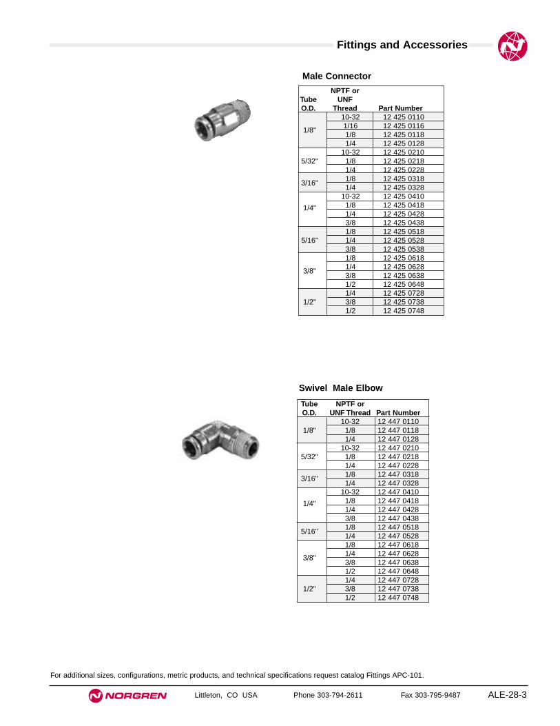
Fittings and Accessories
Littleton, CO USA Phone 303-794-2611 Fax 303-795-9487 ALE-28-3
Male Connector
NPTF orTube UNFO.D. Thread Part Number
10-32 12 425 01101/16 12 425 01161/8"1/8 12 425 01181/4 12 425 0128
10-32 12 425 02105/32" 1/8 12 425 0218
1/4 12 425 02281/8 12 425 03183/16"1/4 12 425 0328
10-32 12 425 0410
1/4" 1/8 12 425 04181/4 12 425 0428 3/8 12 425 04381/8 12 425 0518
5/16" 1/4 12 425 05283/8 12 425 05381/8 12 425 06181/4 12 425 06283/8"3/8 12 425 06381/2 12 425 06481/4 12 425 0728
1/2" 3/8 12 425 07381/2 12 425 0748
Tube NPTF orO.D. UNF Thread Part Number
10-32 12 447 01101/8" 1/8 12 447 0118
1/4 12 447 012810-32 12 447 0210
5/32" 1/8 12 447 02181/4 12 447 02281/8 12 447 03183/16"1/4 12 447 0328
10-32 12 447 0410
1/4" 1/8 12 447 04181/4 12 447 04283/8 12 447 04381/8 12 447 05185/16"1/4 12 447 05281/8 12 447 06181/4 12 447 06283/8"3/8 12 447 06381/2 12 447 06481/4 12 447 0728
1/2" 3/8 12 447 07381/2 12 447 0748
Swivel Male Elbow
For additional sizes, configurations, metric products, and technical specifications request catalog Fittings APC-101.

TubeO.D. NPTF Thread Part Number
1/8 12 426 02185/32"1/4 12 426 02281/8 12 426 04181/4"1/4 12 426 04281/4 12 426 06283/8"3/8 12 426 0638
Fittings and Accessories
Littleton, CO USA Phone 303-794-2611 Fax 303-795-9487ALE-28-4
Tube NPTFO.D. Thread Part Number1/8" 1/8 12 445 0118
1/8 12 445 02185/32"1/4 12 445 02281/8 12 445 03183/16"1/4 12 445 03281/8 12 445 0418
1/4" 1/4 12 445 04283/8 12 445 04381/8 12 445 05185/16"1/4 12 445 05281/8 12 445 06181/4 12 445 06283/8"3/8 12 445 06381/2 12 445 06481/4 12 445 0728
1/2" 3/8 12 445 07381/2 12 445 0748
Male Elbow
Tube NPTF orO.D. UNF Thread Part Number
10-32 UNF 12 467 01101/8" 1/8 12 467 0118
1/4 12 467 012810-32 UNF 12 467 0210
5/32" 1/8 12 467 02181/4 12 467 02281/8 12 467 0418
1/4" 1/4 12 467 04283/8 12 467 04381/8 12 467 05185/16"1/4 12 467 05281/8 12 467 06181/4 12 467 06283/8"3/8 12 467 06381/2 12 467 06481/4 12 467 0728
1/2" 3/8 12 467 07381/2 12 467 0748
Swivel Male Branch Tee
Tube NPTF orO.D. UNF Thread Part Number
10-32 UNF 12 468 02105/32" 1/8 12 468 0218
1/4 12 468 02281/8 12 468 0418
1/4" 1/4 12 468 04283/8 12 468 04381/8 12 468 06181/4 12 468 06283/8"3/8 12 468 06381/2 12 468 06481/4 12 468 0728
1/2" 3/8 12 468 07381/2 12 468 0748
Swivel Male Run Tee
Female Connector
TubeO.D. Part Number1/8" 12 020 01005/32" 12 020 02001/4" 12 020 04005/16" 12 020 05003/8" 12 020 06001/2" 12 020 0700
Union
Union Tee
TubeO.D. Part Number1/8" 12 060 01005/32" 12 060 02001/4" 12 060 04005/16" 12 060 05003/8" 12 060 06001/2" 12 060 0700
TubeO.D. Part Number5/32" 12 040 02001/4" 12 040 04005/16" 12 040 05005/16" 12 040 05003/8" 12 040 06001/2" 12 040 0700
Union Elbow
StemO.D. Part Number5/32'' 11 004 04001/4'' 94 050 9045/16'' 11 004 08003/8'' 94 050 9061/2" 94 050 907
Plug*
*Material: Thermoplastic
TubeO.D. Part Number1/8" 12 029 01005/32" 12 029 02003/16" 12 029 03001/4" 12 029 04005/16" 12 029 05003/8" 12 029 06001/2" 12 029 0700
Bulkhead Union
For additional sizes, configurations, metric products, and technical specifications request catalog Fittings APC-101.

Fittings and Accessories
Littleton, CO USA Phone 303-794-2611 Fax 303-795-9487 ALE-28-5
Tube End ReducerTube StemO.D. O.D. Part Number
1/4" 12 023 04025/32"3/8" 12 023 0602
1/4"3/8" 12 023 06041/2" 12 023 0704
3/8" 1/2" 12 023 0706
Tube TubeO.D. O.D(2x) (1x) Part Number5/32" 5/32" 12 082 02005/32" 1/4" 12 082 04021/4" 1/4" 12 082 0400
Parallel Union “Y” Connector*
*Body Material: Thermoplastic
Operation:Flow Controls are meter out type. Compressed air passes freelyinto the push-in fitting portion of the flow control, flowing past thecheck seal and entering the connected component. In reverse flowconditions, air passes back into the flow control and energizes thecheck seal. Air must now flow through the metered passagecontrolled by the tapered adjustment needle of the flow control, andfinally exits through the push-in fitting end.Specifications
Fluid: Compressed air.Working Pressure: 5 to 150 psig (.3 to 10 bar)Temperature Range: 0° to 175°F (-20° to 80°C)
Materials of Construction:Banjo bolt, body, collet: Nickel plated brassTapered adjusting needle: BrassO-rings and check-seal: Silicone free NitrileSealing washer: Thermoplastic (10-32 UNF)Tubing: Nylon 11 or 12, 95 durometer polyurethane.Thread Sealant: Applied to the full circumference of tapered malethreads.
Free Flow In(Metered Flow Out)
Free Flow Out(Metered Flow In)
Tapered AdjustmentNeedle
Check Seal
Pneumatic Symbol
NPTTube or UNFO.D. Thread Part Number
10-32 UNF 12 VB0 02105/32"
1/8 12 VB0 0218
1/8 12 VB0 04181/4"
1/4 12 VB0 0428
1/4 12 VB0 06283/8"
3/8 12 VB0 0638
3/8 12 VB0 07381/2"
1/2 12 VB0 0748
VB0 Series
NPT NPTFemale Male Part Number
1/8 1/8 12 VB0 18181/4 1/4 12 VB0 28283/8 3/8 12 VB0 38381/2 1/2 12 VB0 4848
Right Angle (Banjo) Flow Controls
For additional sizes, configurations, metric products, and technical specifications request catalog Fittings APC-101.

Fittings and Accessories
Littleton, CO USA Phone 303-794-2611 Fax 303-795-9487ALE-28-6
Technical Data
Fluid: Compressed air, nitrogen, inert and non-combustible gasescompatible with materials of construction.
Operating Pressure:26.8" Hg vacuum to 230 psi (-0.9 to 16 bar)
Operating Temperature:0°* to 175°F (–20°* to 80°C)* Consult our Technical Service for use below 35°F (2°C)
O.D.Model Tube
T50Y0002 5⁄32"T50Y0004 1⁄4"T50Y0005 5⁄16"T50Y0006 3⁄8"T50Y0007 1⁄2"
ISO Symbol
1 2
Technical Data
Fluid: Compressed air, nitrogen, inert and non-combustible gasescompatible with materials of construction.
Operating Pressure:Primary (inlet) pressure 0 to 150 psi (0 - 10 bar)Maximum secondary (regulated) pressure 115 psi (8 bar)
Operating Temperature:0° to 175°F (-20° to +80°C)
Pressure Reducing Fitting - 124GBIn-line Push-in5/32" - 1/2" O.D. tube1/8 - 1/2 NPTF pipe
Check Valves - T50In-line Push-in5/32" - 1/2" O.D. tube
Part O/D NPTFNumber Tube Thread
12 4GB 0218 5⁄32 1⁄812 4GB 0418 1⁄4 1⁄812 4GB 0428 1⁄4 1⁄412 4GB 0528 5⁄16 1⁄412 4GB 0538 5⁄16 3⁄812 4GB 0638 3⁄8 3⁄812 4GB 0748 1⁄2 1⁄2
2
1
Technical Data
Fluid: Compressed air, nitrogen, inert and non-combustible gasescompatible with materials of construction.
Operating Pressure:15-150 psi (1 - 10 bar)
Operating Temperature:0° to 175°F (-20° to +80°C)
Pilot Operated Check Valve - 124GAIn-line Push-in1/4" - 1/2" O.D. tube1/8 - 1/2 NPTF pipe
Product O.D. NPTFNumber Tube Thread
12 4GA 0418 1⁄4" 1⁄812 4GA 0428 1⁄4" 1⁄412 4GA 0638 3/8" 3/812 4GA 0748 1⁄2" 1⁄2
12
12
For additional sizes, configurations, metric products, and technical specifications request catalog Fittings APC-101.
Pressure Reducing Fitting: It is often necessary to provide a secondary reducedpressure to an actuator to control its operating force. A pressure reducing fittingprovides this function, and can be manually adjusted to the required pressure level.
Pilot Operated Check Valve: A blocking fitting which allows air flow in bothdirections if a pilot pressure is applied to port 12. When pressure to the pilot port isremoved flow occurs in one direction only due to an integral control valve. Whenused in pairs, blocking fittings can control an actuator to give controlled operation inthe event of an electrical problem, air failure, or tube breakage.
ISO Symbol
ISO Symbol
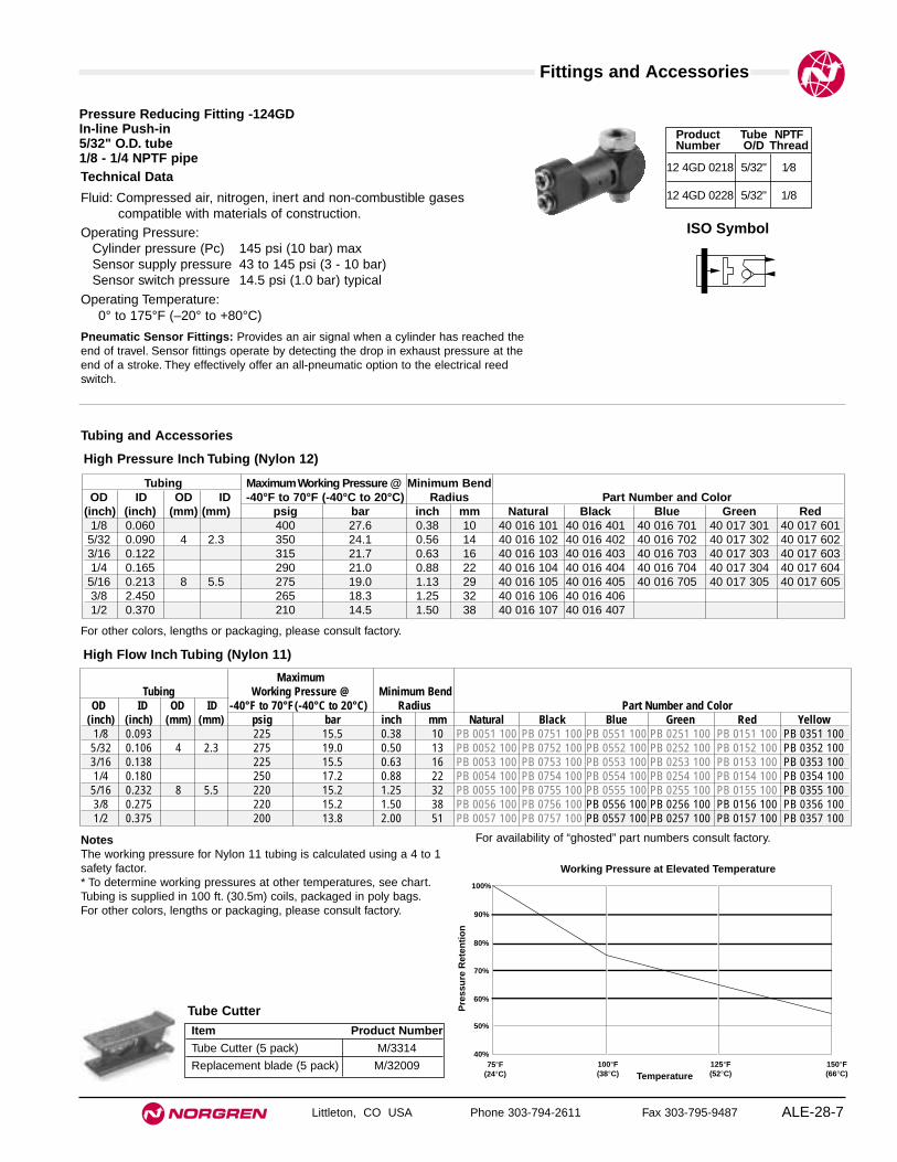
Fittings and Accessories
Littleton, CO USA Phone 303-794-2611 Fax 303-795-9487 ALE-28-7
Technical Data
Fluid: Compressed air, nitrogen, inert and non-combustible gasescompatible with materials of construction.
Operating Pressure:Cylinder pressure (Pc) 145 psi (10 bar) maxSensor supply pressure 43 to 145 psi (3 - 10 bar)Sensor switch pressure 14.5 psi (1.0 bar) typical
Operating Temperature:0° to 175°F (–20° to +80°C)
Product Tube NPTFNumber O/D Thread
12 4GD 0218 5/32" 1⁄8
12 4GD 0228 5/32" 1/8
High Pressure Inch Tubing (Nylon 12)
NotesThe working pressure for Nylon 11 tubing is calculated using a 4 to 1safety factor.* To determine working pressures at other temperatures, see chart.Tubing is supplied in 100 ft. (30.5m) coils, packaged in poly bags.For other colors, lengths or packaging, please consult factory.
Tubing Maximum Working Pressure @ Minimum BendOD ID OD ID -40°F to 70°F (-40°C to 20°C) Radius Part Number and Color
(inch) (inch) (mm) (mm) psig bar inch mm Natural Black Blue Green Red1/8 0.060 400 27.6 0.38 10 40 016 101 40 016 401 40 016 701 40 017 301 40 017 6015/32 0.090 4 2.3 350 24.1 0.56 14 40 016 102 40 016 402 40 016 702 40 017 302 40 017 6023/16 0.122 315 21.7 0.63 16 40 016 103 40 016 403 40 016 703 40 017 303 40 017 6031/4 0.165 290 21.0 0.88 22 40 016 104 40 016 404 40 016 704 40 017 304 40 017 6045/16 0.213 8 5.5 275 19.0 1.13 29 40 016 105 40 016 405 40 016 705 40 017 305 40 017 6053/8 2.450 265 18.3 1.25 32 40 016 106 40 016 4061/2 0.370 210 14.5 1.50 38 40 016 107 40 016 407
High Flow Inch Tubing (Nylon 11)
MaximumTubing Working Pressure @ Minimum Bend
OD ID OD ID -40°F to 70°F(-40°C to 20°C) Radius Part Number and Color(inch) (inch) (mm) (mm) psig bar inch mm Natural Black Blue Green Red Yellow
1/8 0.093 225 15.5 0.38 10 PB 0051 100 PB 0751 100 PB 0551 100 PB 0251 100 PB 0151 100 PB 0351 1005/32 0.106 4 2.3 275 19.0 0.50 13 PB 0052 100 PB 0752 100 PB 0552 100 PB 0252 100 PB 0152 100 PB 0352 1003/16 0.138 225 15.5 0.63 16 PB 0053 100 PB 0753 100 PB 0553 100 PB 0253 100 PB 0153 100 PB 0353 1001/4 0.180 250 17.2 0.88 22 PB 0054 100 PB 0754 100 PB 0554 100 PB 0254 100 PB 0154 100 PB 0354 1005/16 0.232 8 5.5 220 15.2 1.25 32 PB 0055 100 PB 0755 100 PB 0555 100 PB 0255 100 PB 0155 100 PB 0355 1003/8 0.275 220 15.2 1.50 38 PB 0056 100 PB 0756 100 PB 0556 100 PB 0256 100 PB 0156 100 PB 0356 1001/2 0.375 200 13.8 2.00 51 PB 0057 100 PB 0757 100 PB 0557 100 PB 0257 100 PB 0157 100 PB 0357 100
100%
90%
80%
70%
60%
50%
40%75°F
(24°C)100°F(38°C)
125°F(52°C)
150°F(66°C)Temperature
Pre
ssu
re R
eten
tio
n
Working Pressure at Elevated Temperature
For other colors, lengths or packaging, please consult factory.
Item Product Number
Tube Cutter (5 pack) M/3314
Replacement blade (5 pack) M/32009
Pressure Reducing Fitting -124GDIn-line Push-in5/32" O.D. tube1/8 - 1/4 NPTF pipe
Tube Cutter
Tubing and Accessories
ISO Symbol
Pneumatic Sensor Fittings: Provides an air signal when a cylinder has reached theend of travel. Sensor fittings operate by detecting the drop in exhaust pressure at theend of a stroke. They effectively offer an all-pneumatic option to the electrical reedswitch.
For availability of “ghosted” part numbers consult factory.

Fittings and Accessories
Littleton, CO USA Phone 303-794-2611 Fax 303-795-9487ALE-28-8
Port ModelSize NPT
1⁄8 C/5201⁄4 C/5213⁄8 C/5321⁄2 C/5223⁄4 C/5231 C/524
Port Size NPT Model
1/8 T70A 1800
1/4 T70A 2800
3/8 T70A 3800
1/2 T70A 4800
Port Size NPT Model1/8 T1000A1800 1/4 T1000A2800 3/8 T1000A3800 1/2 T1000A4800
Port Size NPT Model1/8 T65A18001/4 T65A2800
Port Part PartSize Number NumberNPT (male) (female)1/8 MB001A MA001A1/4 MB002A MA002A3/8 MB003A MA003A1/2 MB004A MA004A3/4 MB006A MA006A1 MB008A MA008A
Port Size PartNPT Number
10-32 MS000A1/8 MS001A1/4 MS002A3/8 MS003A1/2 MS004A3/4 MS006A1 MS008A
Port PartSize NPT Number
10-32 UNF M/S01⁄8 C/S11⁄4 C/S23⁄8 C/S31⁄2 C/S43⁄4 C/S61 C/S8
Port Size PartNPT Number1/8 MV001A1/4 MV002A3/8 MV003A1/2 MV004A3/4 MV006A1 MV008A
Port Size PartNPT Number
10-32 UNF T20M05001/8 T20A18001/4 T20A28003/8 T20A38001/2 T20A4800
Port Size PartNPT Number1/8 MM001A1/4 MM002A3/8 MM003A1/2 MM004A
Check Valves In-line Flow Controls
Quick Exhaust Valves Shuttle Valves
Quietaire™ Pneumatic Silencers
Standard-duty,sintered bronze
Standard-dutyporous plastic
Breather ventsintered bronze
Heavy duty speed controlsintered bronze
Standard-duty speed control porous plastic
Heavy-duty shell type
For additional sizes, configurations, metric products, and technical specifications request catalog Fittings APC-101.V

Littleton, CO USA Phone 303-794-2611 Fax 303-795-9487
● Miniature pneumatic interface amplifiers● Sense very low pneumatic signals● Provide on/off control of a high pressure air
supply● Low and ultra-low pressure models● Used with non-contact sensors to amplify
outputs to a usable level● Serves as an output device in miniature
pneumatic circuits
Operation:Supply pressure travels through an orifice and is vented to atmosphere.When a control signal is applied, it energizes a diaphragm, compressinga spring and cutting off the vent passage. Pressure is now directed fromthe supply to outlet port, providing an amplified signal.When the control signal is removed, the spring returns the diaphragm toits non-energized position, and the supply signal is once again vented toatmosphere.
SpecificationsFluid: Compressed air, nitrogen, or inert gasesMax. Control Pressure: 5 psig (.3 bar)Inlet Pressure
Minimum: 0 psig (0 bar)Maximum: 125 psig (8.6 bar)
Temperature Range: 35° to 150°F (2° to 66°C)Equivalent Orifice Size: 0.014" (.36 mm)Cycle Rate: 25 HzPorts: 10-32 UNF
Materials of ConstructionBody: NorylEnd Cap: PolycarbonateSpring: Stainless steelDiaphragm: Buna-N
Diaphragm Amplifiers
ALE-28-9
Part Port Positive On/Off Actuation PointsNumber Thread ON - when control signal is more than: OFF - when control signal is less than:
5DA-010-D0A 10-32 UNF 4" H2O (10 mbar) 1" H2O (2.5 mbar)5DA-011-D0A 10-32 UNF 10" H2O (25 mbar) 5" H2O (12.5 mbar)
Ordering InformationTo order, quote appropriate product number from thetables on the following pages, e.g.5DA-010-D0A for control of systems where actuationis required above a 4" H2O signal with the outputresetting to off when the control signal falls below 1"H2O.
IN OUT
Control
Pneumatic Symbol
1.38
(34
)
.88 (22)
.88 (22)
.25 (6)
1.38 (34)
.25 (6)
1.16 (30)10-32 UNF3-Places TYP.
TYP.
Furnished with three adapters for use with 1/16" ID flexible tubing.

Littleton, CO USA Phone 303-794-2611 Fax 303-795-9487ALE-28-10
● Visual indication of system status● Indicate presence or absence of pressure● Large (13/16") or small (7/16") lens● Choice of connections● Contrasting, fluorescent indicator colors
OperationPressure applied to an internal piston/diaphragm assembly compresses aspring, moving a linkage which rotates the colored indicator ball. Whenfull actuation pressure is reached, the indicator ball rotates fully, changingthe indicator color.When the pressure signal is removed, the internal spring returns theindicator ball to its non-actuated color/position.
Rotowink Indicators
SpecificationsFluid: Compressed air, nitrogen, or inert gasesAir Consumption: NoneWorking Pressure: See order chart FIT-9-9.Temperature Range: 35° to 150°F (2° to 66°C)
Materials of ConstructionBody:
5VS-1XX-XXX - Acetal5VS-4XX-XXX - Polyphenylene5VS-2XX-XXX - Acetal
End Plug:5VS-1XX-XXX - Acetal5VS-4XX-XXX - Aluminum
Piston: AcetalElastomer: Buna-NLens: Acrylic
OptionsSpecial versions of the Rotowink are available,please consult factory with specific requirements and quantities.
Ordering InformationTo order, quote appropriate product number from thetables on the following pages, e.g. 5VS-401-00 for1/8 NPT female connection, black/red indication,and 10 psig actuation pressure.

Rotowink Indicators
Littleton, CO USA Phone 303-794-2611 Fax 303-795-9487 ALE-28-11
All Dimensions in Inches (mm)
.76
(19)
dia
.
.83
(21)
dia
.
.44 (11)
.03 to .25(.8 to 6.4)
.88 (22)
10-32 UNF
.78
(20)
dia
.
.83
(21)
dia
.
.44 (11)
.03 to .25(.8 to 6.4)
1.38 (35)
1/8-27 NPTF
1.44
(37
) d
ia.
1.52
(39
) d
ia.
.71 (18)
.03 to .25(.8 to 6.4)
1.54 (39)
1/8-27 NPTF
Colors Operating Pressure Ranges
(Standard combinations 1 to 15 psig 10 to 125 psig 15 to 150 psig
listed. Other combinations available.) (.07 to 1 bar) (.7 to 8.6 bar) (1 to 10.3 bar)NPT or UNF Thread Port
10-32 UNF* 1/8 NPTF 1/8 NPTFNormal Actuated (Female) (Female) (Male)
Part NumbersBlack Red 5VS-101-000 5VS-401-000 5VS-201-000Black Green 5VS-102-000 5VS-402-000 5VS-202-000Black Yellow 5VS-103-000 5VS-403-000 –Red Green 5VS-112-000 5VS-412-000 5VS-212-000
Green Red 5VS-121-000 5VS-421-000 5VS-221-000Specifications
Maximum Pressure -psig (bar) 15 (1) 125 (8.6) 150 (10.3)
Actuation Pressure -psig (bar) 1 (.07) 10 (.7) 15 (1)
Deactuation Pressure -psig (bar) 15" H2O (38 mbar) 2 (.14) 2 (.14)
Mounting Hole Ø - in. (mm) .72 (18.3) 1.22 (31.0) .72 (18.3)
*Furnished with an adapter for use with 1/16" ID flexible tubing.
5VS-1XX Series 5VS-2XX Series
5VS-4XX Series

Littleton, CO USA Phone 303-794-2611 Fax 303-795-9487ALE-28-12
● Visual indication of differential pressure levels● Full 360° visibility of RED/GREEN pressure
indicator● Light weight construction● 1/8 NPT (female) connections● In-line or bottom porting
Differential Pressure Indicators
SpecificationsFluid: Compressed air, nitrogen or inert gasesMax. Inlet Pressure: 250 psig (17.2 bar)Temperature Range: 0° to 175°F (-18° to 79°C)Max. Differential Pressure: 15 psid (1 bar d)Ports: 1/8 NPT (female)
Materials of ConstructionIndicator Body: Transparent nylonAdapter Body: AluminumInternal Parts: AcetalSpring: Stainless steelElastomers: Nitrile
.88 (22)1/8 PTF
1.70
(43
)
2.06
(52
)
1.61 (41)
1.59 (40)Inline Ported
Bottom Ported
Part Port Differential Indicator Color Code - (∆P range)Number Location Range GREEN GREEN/RED RED
18-033-104 In-line 0 to 5 psid less than 0.5 psid between 0.5 and 4.5 psi greater than 4.5 psid18-033-105 Bottom (0 to 0.35 bar d) (0.04 bar d) (0.04 and 0.31 bar d) (0.31 bar d)18-033-101 In-line 0 to 10 psid less than 4 psid between 4 and 10 psid greater than 10 psid18-033-102 Bottom (0 to 0.7 bar d) (0.3 bar d) (0.3 and 0.7 bar d) (0.7 bar d)

Littleton, CO USA Phone 303-794-2611 Fax 303-795-9487 ALE-28-13
● Integrates pneumatic and electrical systems● Low actuation pressure● Panel mountable● Single-pole Double-throw operation● May be wired Normally-open or Normally-closed
Operation:Signal pressure extends a diaphragm which contacts and actuates anelectrical micro-switch.
SpecificationsFluid: Compressed air, nitrogen, or inert gasesMax. Working Pressure: 15 psig (1 bar)Actuation Pressure: 1 psig (.07 bar)Temperature Range: 35° to 150°F (2° to 66°C)Electrical Rating: 5 Amps 125/250 VacAir Consumption: 0Panel Mounting Hole: Ø1-7/32" (31 mm)
Panel Thickness: 0.03 to 0.25" (.8 to 6.4 mm)Connections
Pneumatic: 10-32 UNFElectrical: 0.093 female spade (3x)
Materials of ConstructionBody and Locknut: AluminumSwitch Carrier: NorylDiaphragm: PolyurethaneDiaphragm Plate: Nylon
Order Number - 5FE-010-000
Crimp type, insulated, male spade electrical terminals for 18-22 gaugewire are furnished with each switch.
Pressure Switch
Pneumatic Symbol
1.38
(35
)
1.56
(39
)
.88 (22)10-32 UNF .25 (6)
NC
NO
C
.03 to .25 (.8 to 6.4)
5FE-010-000

Littleton, CO USA Phone 303-794-2611 Fax 303-795-9487ALE-28-14
● Compact pneumatic power amplifiers● Sense very low pneumatic signals● Provide on/off control of a high pressure air
supply● Low and ultra-low pressure models● Inputs (control) from pneumatic sensors, logic
devices, instrumentation systems● Provide direct operation of small actuators
(cylinders), large air piloted valves, and othersmall pneumatic devices
● Average service life exceeding 100 millioncycles
Boostermites
OperationBoostermites are bleed actuated, 2-position, 3-way, 3-port, normallyclosed poppet valves. Supply pressure travels through an orifice and isvented to atmosphere. When a control signal is applied, it energizes adiaphragm, compressing a spring and cutting off the vent passage.Pressure is now directed from the supply to the poppet piston, whichshifts the valve, connecting the inlet to the outlet ports. When the controlsignal is removed, the spring returns the diaphragm to its non-energizedposition, and the supply signal is once again vented to atmosphere, andthe poppet piston shifts the valve to the non-actuated position.
SpecificationsFluid: Filtered (25µ), lubricated or non-lubricated compressed airMax. Control Pressure: 5 psig (.3 bar)Inlet Pressure
Minimum: 20 psig (1.4 bar)Maximum: 125 psig (8.6 bar)
Temperature Range: 35° to 150°F (2° to 66°C)Equivalent Orifice Size: 0.094" (2.4 mm)Cycle Rate: 900 cpmPorts
Control: 10-32 UNFMain: 1/8 PTF
Materials of ConstructionBody: AluminumPiston Assembly: Aluminum, AcetalEnd Caps: Polycarbonate, NylonSprings: Stainless steelElastomers: Buna-NService Kit (includes seals) Part Number: P0150A-01
Ordering InformationTo order, quote appropriate product number from thetables on the following pages, e.g. 5BV-011-D0A foroperation of pneumatic devices where actuation isrequired above a 3" H2O signal with the outputresetting to off when the control signal falls below1/2" H2O.
INEX
OUT
Control
Pneumatic Symbol

Boostermites
Littleton, CO USA Phone 303-794-2611 Fax 303-795-9487 ALE-28-15
All Dimensions in Inches (mm)
*Variation with attitude change: 1/2" H2O (1.3 mbar)Furnished with two 1/2" long mounting spacers and a control port adapter for use with 1/16" ID flexible tubing.
Part Port Thread Positive On/Off Actuation PointsNumber Control Main ON - when control signal is more than*: OFF - when control signal is less than:
5BV-011-10A 10-32 UNF 1/8 PTF 3" H2O (7.5 mbar) 1/2" H2O (1.3 mbar)5BV-010-10A 10-32 UNF 1/8 PTF 10" H2O (25 mbar) 5" H2O (12.5 mbar)
1/8-27PTF
3 Places
2.09
(53
)1.
33 (
34)
10-32 UNF
.19 (5)2 Places
.88(22.4)
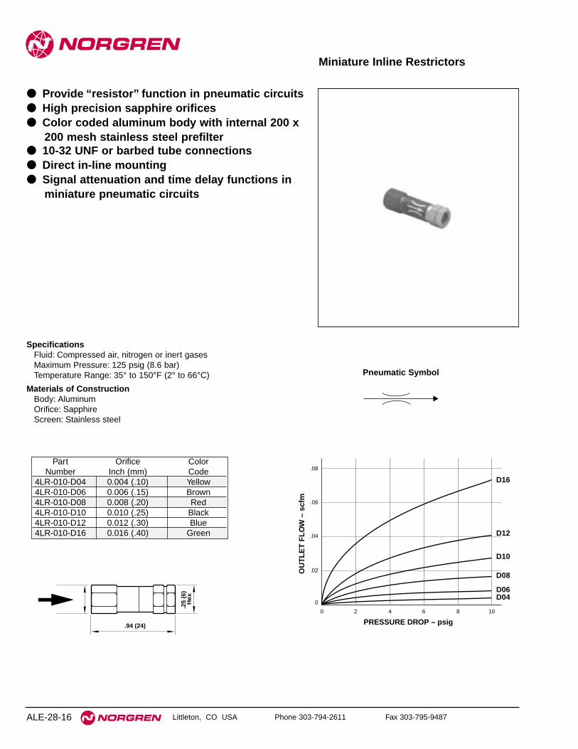
Littleton, CO USA Phone 303-794-2611 Fax 303-795-9487ALE-28-16
Miniature Inline Restrictors
SpecificationsFluid: Compressed air, nitrogen or inert gasesMaximum Pressure: 125 psig (8.6 bar)Temperature Range: 35° to 150°F (2° to 66°C)
Materials of ConstructionBody: AluminumOrifice: SapphireScreen: Stainless steel
.25
(6)
Hex
.94 (24)
.08
D16
D12
D10
D08
D06D04
.06
.04
.02
0
0 2 4 6 8 10
OU
TL
ET
FL
OW
– s
cfm
PRESSURE DROP – psig
Part Orifice ColorNumber Inch (mm) Code
4LR-010-D04 0.004 (.10) Yellow4LR-010-D06 0.006 (.15) Brown4LR-010-D08 0.008 (.20) Red4LR-010-D10 0.010 (.25) Black4LR-010-D12 0.012 (.30) Blue4LR-010-D16 0.016 (.40) Green
Pneumatic Symbol
● Provide “resistor” function in pneumatic circuits● High precision sapphire orifices● Color coded aluminum body with internal 200 x
200 mesh stainless steel prefilter● 10-32 UNF or barbed tube connections● Direct in-line mounting● Signal attenuation and time delay functions in
miniature pneumatic circuits

Littleton, CO USA Phone 303-794-2611 Fax 303-795-9487 ALE-28-17
● 25-micron element rating● Connections for 1/8" or 5/32" ID flexible tubing● Direct in-line mounting● Protection against particulate contamination for
miniature pneumatic systems
Miniature Inline Filters
SpecificationsFluid: Compressed air, nitrogen or inert gasesElement Rating: 25µMaximum Pressure: 60 psig (4.1 bar)Maximum Temperature: 125°F (52°C)
Materials of ConstructionBody: PolypropyleneElement: Sintered BronzeElastomers: Buna-N
A d
ia.
C dia
.
B
6
psig
bar
.4
.3
.2
.1
0
4
2
0
PR
ES
SU
RE
DR
OP
FLOW
0
0
.4
.2
.8
.4
1.2
.6
1.6
.8
2.0 scfm
1.0 dm3/s
4LF-010-000
FLUID: AirINLET PRESSURE: Noted – psig (bar)
10(.69)
20(1.38)
30(2.07)
6
psig
bar
.4
.3
.2
.1
0
4
2
0
PR
ES
SU
RE
DR
OP
FLOW
0
0
.4
.2
.8
.4
1.2
.6
1.6
.8
2.0 scfm
1.0 dm3/s
4LF-020-000
10(.69)
20(1.38)
30(2.07)
FLUID: AirINLET PRESSURE: Noted – psig (bar)
Part Flexible TubeNumber Connection
4LF-010-000 1/8" ID4LF-020-000 5/32" ID
Part Number ØA ØC B4LF-010-000 0.15 (3.8) 0.64 (6.3) 1.58 (40.1)4LF-020-000 0.18 (4.6) 0.64 (16.3) 1.70 (43.2)
Pneumatic Symbol


Littleton, CO USA Phone 303-794-2611 Fax 303-795-9487 ALE-29-1
Section 29
Contents
Lubricants For Use With Norgren Airline Products . . . . . . . . . . . .ALE-29-2
Glossary of Pneumatic Terms . . . . . . . . . . . . . . . . . . . . . . . . . . . . .ALE-29-3
Improving the Bottom Line with Pneumatics . . . . . . . . . . . . . . . . .ALE-29-6
Helpful Engineering Information . . . . . . . . . . . . . . . . . . . . . . . . . .ALE-29-10
Conversion Tables . . . . . . . . . . . . . . . . . . . . . . . . . . . . . . . . . . . . .ALE-29-12
Thread Forms . . . . . . . . . . . . . . . . . . . . . . . . . . . . . . . . . . . . . . . .ALE-29-13
Norgren Web Site . . . . . . . . . . . . . . . . . . . . . . . . . . . . . . . . . . . . . .ALE-29-16
Warning and Warranty . . . . . . . . . . . . . . . . . . . . . . . . . . . . . . . . . .ALE-29-17
Part Index . . . . . . . . . . . . . . . . . . . . . . . . . . . . . . . . . . . . . . . . . . . .ALE-29-18
Appendix

Recommended Lubricants
Littleton, CO USA Phone 303-794-2611 Fax 303-795-9487ALE-29-2
Assembly GreasesThe following greases may be used in thereassembly of Norgren Airline Equipment.
Recommended Oils for use with Norgren LubricatorsOils listed in the following tables may be used in Norgren Lubricators. Alloils, however, may not be compatible with the equipment to be lubricated.Contact your lubricant supplier and the builder of the equipment to belubricated to obtain specific lubricant recommendations.
Low Temperature Applications - For use when temperature remains below 32°F (0°C)
ISO 3448Manufacturer Product Viscosity NumberMOBIL SHC 624 32DUCKHAMS Zeroflo 32 32MOBIL S4C 524 32
ISO 3448Manufacturer Product Viscosity NumberBRITISH PETROLEUM Energal HLP10 10CASTROL Hyspin AWS10 10MOBIL Velocite Oil No. 6 10SHELL Tellus R10 10TOTAL Azolla ZS10 10CENTURY P198 15DUCKHAMS Zeroflo 15 15ELF Elfolna 15 15ESSO Nuto H15 15MOBIL Velocite Oil No. 8 15ROCOL MO-4 15MOBIL Velocite Oil No. 10 22SHELL Tellus 22 22
Antifreeze Lubrication
Manufacturer ProductCASTROL Antifreeze Mist Lubricant
Industrial Compressed Air Applications
Manufacturer ProductBRITISH PETROLEUM Energrease LS2 (non-silicone)DOW CORNING Molykote BR-2 Plus (non-silicone)CARLETON-STUART Magnalube G (non-silicone)DOW CORNING DC44 (silicone)DOW CORNING DC55 (silicone)
Food and Potable Water Applications
Manufacturer ProductDOW CORNING Molykote 111 (silicone)
Low Temperature Industrial Compressed Air Applications below-20°F (-29°C)
Manufacturer ProductKLUBER Unisilicon L50/2 (silicone)
ISO 3448Manufacturer Product Viscosity NumberBRITISH PETROLEUM Energal HLP32 32CASTROL Hyspin AWS32 32CENTURY PWLA 32ELF Elfolna 32 32ESSO Nuto H32 32GULF Harmony 32 32MOBIL SHC 524 32MOBIL DTE 24 32MOBIL DTE Oil Light 32MOBIL Gargoyle Arctic Oil Light 32SHELL Tellus 32 32TEXACO Rondo 32 32SHELL Tellus 37 37GULF Hydrasil 46 46BRITISH PETROLEUM Energal HLP46 46SHELL Tellus 46 46TEXACO Regal Oil R & 046 46ROCOL MO-10 46BRITISH PETROLEUM Energal HLP68 68 *
Light Duty Tool Lubricants (ISO 3448 Viscosity Grades 10 to 22) for Small Air Tools
Heavy Duty Tool Lubricants (ISO 3448 Viscosity Grades 32 to 68) for Standard Air Toolsand Cylinders
* For certain applications requiring heavy oil.

Glossary
Littleton, CO USA Phone 303-794-2611 Fax 303-795-9487 ALE-29-3
Activated CarbonA filter material (media) used to remove odors and oil vaporsfrom compressed air.
AerosolA suspension of fine liquid particles in gas, i.e., smoke, fog,and mist
After CoolerA heat exchanger mounted on a compressor outlet to extractthe heat of compression.
Air-Piloted Pressure RegulatorSee Pilot Operated Regulator
AmbientThe normal condition of air usually defined by temperature or
humidity in the vicinity of the equipment being evaluated.Automatic Drain
A mechanical float used to open and drain excess fluids froma filter bowl (these drains are normally open and usepressure to close)
Average Flow Typical rate of instantaneous flow over a given timeframe (used
to determine compressor capacity requirement). SeeInstantaneous Flow.
Back Pressure RegulatorSee relief valve
Balanced Valve, RegulatorA term used to denote the use of equal pressure on bothsides of regulator valve to balance and minimize effect ofchanging primary pressure.
Bearing LubricatorMicro-Fog lubricator (See Micro-Fog Lubricator) normallyused to lubricate machine bearings.
Beverage RegulatorRegulator normally used for tank systems, often high-pressure, of inert gases (i.e., CO2) and used in conjunctionwith beverage dispensing equipment.
Check ValveA device which allow flow in one direction only.
Coalescing:The action causing small oil aerosols to combines throughadsorption to form larger, heavier, droplets for removal formthe compressed air stream.
Coalescing FilterFilter using coalescing element to remove oil aerosolparticles.
CFMCubic Feet per Minute, a volumetric flow measurement at aspecified pressure.
CvA dimensionless number expressing the flow capability or
conductance of a fixed orifice of a pneumatic device Constant Bleed
A method used to reduce or eliminate droop in a regulator toprovide higher performance, more precise flow and fasterregulation characteristics.
CreepUsed to describe increase in secondary pressure (P2) due toa leak from primary pressure (P1).
Critical Back Pressure Ratio (CBPR)CBPR is equal to 53% with compressed air; CBPR is whendownstream pressure is less than 53% of the upstreampressure reducing downstream pressure further will notincrease flow.
Dead End ServiceImplies a secondary volume is pressurized, however, undernormal circumstances the volume does not flow air but actsas a holding vessel.
Deliquescent DryerAn air dryer utilizing chemicals for purposes of dewpointsuppression by absorbing water from a compressed airstream.
Delta-P IndicatorSee Service Life Indicator, Pressure Drop indicator
DesiccantA material creating adherence, or adsorption, of water to itssurface. Often used in regenerative or desiccant dryers tolower the dewpoint for removal of water from compressed air.
Dew PointThe temperature at which moisture begins to condense toliquid at a constant pressure. The temperature at which air issaturated is the dew point and at this point relative humidityis equal to 100%.
Drip Leg DrainA device placed at the low point of a main air distributionsystem used to removed condensed liquid water from thecompressed air stream where water is likely to accumulate.
DroopA term used to describe the initial pressure drop seen in aregulator flow curve (caused by seal impingement).
Dump ValvesSee Exhaust Valves
Electronic RegulatorElectronically controlled regulator used to reduce inletpressures to a regulated process range output.
EmulsionA mixture of oil and water.
ExcelonA Norgren trade name used to describe a modular FRLproduct using a patented one-piece clamping mechanismcalled a Quikclamp.Exhaust ValvesValve used to evacuate downstream air of the valve itself(warning- air can be trapped by other pneumatic devicesdownstream of the valve).
Feedback RegulatorA special pilot regulator designed to sense and controlpressure more accurately at a remote point downstream ofthe pilot operated regulator to provide more consistentpressure control.
Free AirAir at ambient conditions usually measured at a compressorintake (compressors are rated in CFM of Free Air @ Intake).
FlowThe rate of air allowed to pass through a device or orifice ata given pressure, usually in SCFM or dm3/sec. Twoexpressions are commonly associated with flow:instantaneous flow and average flow.
Flow CurveA performance chart showing various flow rates for a specificcomponent at specific pressure settings and pressure drop.
General Purpose FilterFilter used for common liquid extraction and particle removal,normally filtered to 40 or 5 micron particle size.

Glossary
Littleton, CO USA Phone 303-794-2611 Fax 303-795-9487ALE-29-4
General Purpose RegulatorA common regulator used to provide normal industrialpressure regulation.
Instantaneous Flow Flow rate demanded within a single cycle of a compressed air
system (used to size pneumatic components of valves, airpreparation, fittings, and conductors)
Instrument RegulatorA higher precision regulator used to provide exceptionallyclose tolerance pressure regulation.
Integral Filter/RegulatorA unit combining the function of a filter and regulator into onespace-saving unit.
Integral Pilot Operated RegulatorA unit combing the integral pilot operated regulator with themain control regulator
I/P Pressure ConverterEssentially a precision electronic regulator (see alsoElectronic Regulator). Also know as E/P, P/I, and P/Econverters (I = current, E = voltage, P = pressure).
Machine LubricatorSee Micro-Fog or Bearing Lubricator.Manual Drain
A valve that requires manually open and closure to drainliquids from a filter bowl (sometimes used with lubricatorbowls).
Manifolding RegulatorA regulator with two common P1 ports and two common P2ports which can be assembled in a single or multiple outputfashion for various pressure settings using a solitary inlet airline.
Manifold BlockBlock used to connect multiple air line products.
Master RegulatorA term sometimes used to refer to the controlling regulator ofa Pilot Operated Regulator.
Membrane DryerA variable dewpoint suppression device using hollow fiberswhich has an affinity for water, whereby moisture-laden airenters into the fibers and the water vapor permeates throughthe walls to be removed from the air stream.
Micro-Fog LubricatorsA Norgren trade name for lubricators designed to atomize oilto an aerosol within the airflow, usually less than 2 micronsin size, to provide longer travel distance at a higherconsistency of suspended oil in pipes. Typically used withdistances up to 50 feet or when more than one tool requireslubrication from a single lubricator.
MicronA measurement of size equal to one-millionth of a meter(.000039 inch).
NACENational Association of Corrosion Engineers specifyingstandards used to determine corrosion resistancerequirements of products.
Non-Return ValveSee Check Valve
Oil-Fog LubricatorA Norgren trade name for a lubricator designed toheterogeneously disperse oil mist, having particles sizeusually larger than 2 microns to small droplets. Typicallyused for short distances or when only one tool requireslubrication.
Odor Removal filterSee Oil Vapor Removal filter.
Oil Vapor Removal FilterFilter utilizing an activated carbon to remove oil vapor. Alsoused to remove odors from air stream.
OlympianA Norgren trade name to describe European manufacturedFRL products utilizing a modular yoke design.
P1See Primary Pressure
P2See Secondary Pressure.
Pilot Operated or Slave RegulatorA regulator, which has its outlet pressure, controlled by airpilot pressure instead of a spring. Requires anotherpressure regulator to control the pilot pressure.
Porting BlockModular device providing a pipe port(s) from a main airflowstream or pneumatic control mechanism.
Precision Pressure RegulatorA regulator used to provide the most precise pressureregulation without electrical feedback (usually a constantbleed regulator).
Pressure SwitchDevices to monitor pressure and/or provide an output signalin a system.
Pounds Per Square Inch Absolute (PISA)Pressure including atmospheric pressure. Atmosphericpressure is caused by the weight of the atmosphere pushingdown on the earth's surface. (Atmospheric pressure is equalto 14.7 at sea level.)
Pounds Per Square Inch Gauge (PISG)Pressure related and visual on a gauge, not taking intoaccount atmospheric pressure
Pounds per Square Inch Drop (PSID)The amount of pressure loss, in PSI, incurred by the flow of air
through a device (losses usually due to friction and otherfactors).
Pressure Reducing DeviceSee Regulator, Pressure
Primary PressureSupply or inlet pressure, P1.
Prismatic LensA Norgren trade name used to describe a special bowl liquidlevel indicator, a bowl sight lens.
QuikclampNorgren trade name used to describe the patented one-piece clamping mechanism for Norgren EXCELON(r)products
QuikDrainA Norgren trade name for the patented manual 1/4 turn drainfor Norgren Bowls.
Refrigeration DryerAn air dryer utilizing refrigeration to cool air for purposes of
dewpoint suppression in order condense and remove waterfrom a compressed air stream.
Glossary
Littleton, CO USA Phone 303-794-2611 Fax 303-795-9487 ALE-29-5
Regenerative DryerAn air dryer utilizing desiccant for purposes of dewpoint
suppression by method of adsorption in order to accumulateand remove water from a compressed air stream.
Regulation CurveA performance chart of a regulator used to determine theexpected fluctuation of secondary pressure under constantflow with varying primary pressure.
Regulator, PressureA device used to reduce (regulate) air pressure in apneumatic system to a desired working level.
Relief ValveA device used to reduce likelihood of over pressurization of asystem by relieving air at a given pressure set point.
Relative HumidityThe ratio of actual water present in a volume of air, asmeasured as a percentage of air completely saturated at thesame temperature.
Remote Fill DeviceA device used to fill lubricator bowls from a remote location.
Reverse Flow RegulatorA regulator designed to exhaust downstream air with loss of
upstream pressure.SCFM
Standard Cubic Feet per Minute, SCFM converts CFM tostandard conditions: 14.7 PSIZ, 68oF ambient temperature,and 35% relative humidity (See also CFM).
Secondary PressureRegulated pressure downstream of a specific device, P2.
Semi-automatic DrainA drain that requires manual operation to drain whenpressurized, but opens automatically in the absence ofpressure. Sometimes referred to as an overnight drain.
Service Life IndicatorDevice used to visually or electronically indicate pressuredrop (Delta-P), variance in P1 to P2, across a filter used towarn of filter clogging.
Sight Feed DomeThe control device adjustment on a lubricator used toincrease or decrease oil feed rate.
Slave regulatorSee Pilot Operated Regulator
Smooth Start ValveA valve allowing slow pressure build-up of a system to anintermediate pressure before permitting a step-up to full linepressure. Used to prevent sudden movement, damage, andpotential failure of equipment during start-up.
Soft Start ValveSee Smooth Start Valve
SSU or ViscositySabolt Universal Seconds, the time in seconds for 60milliliters of oil to flow through a standard orifice at a giventemperature.
Standard ConditionsThe basis of comparison of ambient conditions, thespecification used to convert CFM as ambient conditions fordirect comparison @ SCFM. (For compressed air:temperature of 680- 720F, relative humidity of 35%, andatmospheric pressure of 14.7 psia.)
Terminal VelocityIn compressed air applications, terminal (critical) velocity isreached when the downstream pressure (P2) is less than53% of the upstream pressure (P1). See also Critical BackPressure Ratio.
Tool LubricatorSee Oil-Fog Lubricator.
Unbalanced ValveA term used to denote where primary pressure is allowed toact as a closing force across the valve seat area. Changesin primary pressure (P1) can impact the secondary pressuresetting (P2).
YokeA term used to describe the connection or mounting methodused in the Olympian Series Product.

Improving the Bottom Line
ALE-29-6 Littleton, CO USA Phone 303-794-2611 Fax 303-795-9487
IMPROVING THE "BOTTOM LINE" WITH PNEUMATICS.Clayton W. Fryer, IMI NORGREN, Littleton, Colorado
Abstract:The cost of compressed air continues to be a very elusivesubject in industrial applications. The notion that compressedair is free is a common misconception. Countless attempts atmaking end users aware of the costs to produce compressedair have largely been ignored. It seems that OperationsManagers are concerned with the power consumption of acouple of sixty-watt light bulbs, but couldn't care less about thepower required to run a 400 horsepower compressor! Let's putthis into perspective, one horsepower equals 745.7 Watts. Youcan light 4,971 sixty-watt light bulbs with the same power ittakes to run a 400 horsepower compressor! Indeed, the singlelargest electrical appliance in a manufacturing plant may be thecompressor motor.
This paper will provide some common sense approaches todetermine the cost of compressed air required in a typicalpneumatic circuit. It is the discovery of the approach and therequisite considerations that we hope to explore. By clearing upseveral popular pneumatic myths, we will be able to makebetter decisions to reduce the cost of compressed air.Compressed air costs are typically hidden in the operatingoverheads of most companies. Any overhead cost reductionimmediately falls to the bottom line in the form of profit.The real test of this improved bottom line is determining theadditional sales a company must generate to produce a similarprofit.Real CostsExperts in the compressed air field suggest the cost to producecompressed air varies from $.15 to $.40 per 1000 StandardCubic Feet (SCF) (1), (2), depending on geographical location.In spite of these estimates, a large sector of the user publicfails to complete the simple calculations to determine what amachine will require in terms of Standard Cubic Feet perMinute (SCFM) of compressed air, let alone for an entire yearor the life of the equipment. In order to improve the bottom linewith pneumatics, we must also expose three popularpneumatic myths!
Myth #1: Compressed Air is FreeMyth #2: Pipe Size = Right SizeMyth #3: If a little bit's good, a whole lot's better
Myth #1: Compressed Air is Free!In the past most people wouldn't take the time to determine thecost of the compressed air required by an actuator for a year. Itis ironic that hydraulic system designers have to do thecalculations in order to determine the size of the power unitrequired to operate hydraulic cylinders. For far too long, littleeffort has been made to recognize the similarities betweenhydraulic and pneumatic systems. Typically, fluid power peoplehave defended the differences between hydraulic andpneumatic systems. By recognizing the similarities, we candesign and service the two mediums from similar perspectives,including the need for safety, conservation, component sizing,and cost justification.
There is a developing interest in determining the cost ofcompressed air in a pneumatic system. We are beginning tosee users specify 60 PSIG as the maximum pressure range fora pneumatic system. Pneumatic component manufacturers aresomewhat paranoid about discussing the cost of compressedair in fear they might encourage customers to apply asubstitute for compressed air. Since compressed air is readilyavailable, affordable, clean, and has less force hazards thanhydraulic power, it seems reasonable that compressed air willcontinue to be applied in the industrial sector.Real Common SenseTo properly apply pneumatic components in a system, the firstcomponent to be considered is the actuator. We have seen alarge number of cylinders grossly oversized resulting in pooractuator performance, wasted compressed air, and high initialcomponent costs. Oversizing an actuator by one bore sizecan result in a fifty percent increase in the cost ofcompressed air required for the application. If the cylinderis sized to move more than twice the load at the designpressure, the cylinder speed will be adversely affected, and thecost of compressed air will also increase. Using this simpleobservation can result in significant savings
If care is taken at this step of the design process, everycomponent upstream of the actuator (valves, conductors,fittings, filters, regulators, and lubricators) will have a betterchance of being correctly sized and applied. A good andcorrect start in the process is essential to having an efficientoperating system.Real CalculationsA Cylinder Flow Calculation is required for a number ofreasons. It takes into consideration the force required to movethe load at the specified pressure, the extend and retract strokevolumes of the cylinder, the cycles per minute, the operating airpressure, and a conversion to Standard Cubic Feet per Minute(SCFM). SCFM is the value used by most pneumatic fluidpower manufacturers to apply the correct components in asystem. SCFM is also linked to valve sizing using Coefficient ofFlow (Cv)
Once the cylinder flow calculation is completed, the designercan determine the correct tubing, fittings, valves, and the Filter,Regulator, and Lubricator (FRL) for the application. In spite ofthe obvious benefits this information provides, we find fewdesigners attempting these critical calculations.
In a typical circuit (Figure 1.) comprised of a double-actingpneumatic cylinder, a five-port, four-way valve, and two flow

Improving the Bottom Line
Littleton, CO USA Phone 303-794-2611 Fax 303-795-9487 ALE-29-7
controls, the typical approach to sizing exposes anotherpopular pneumatic myth.
Myth #2: "Pipesize = Right Size".
Figure 1. Typical valve/cylinder/flow control circuitIf the cylinder selected had a 1/2" pipe port, most installerswould apply 1/2" flow controls, 1/2" pipe and fittings, a 1/2"valve, and quite possibly, a 1/2" FRL! This approach leads tooversized, high priced components and higher long termoperating compressed air costs over the life of the equipment.As a result, oversizing components occurs frequently andquickly leads to another popular pneumatic myth.
Myth #3: If a little bit's good, a whole lot's better!Real Life Example?Let's consider the following example. We have a cylinder loadthat requires 500 pounds of force to move in the extenddirection only. The retract stroke has no effective load. We wantto move the load twelve inches and be able to do this at 30cycles per minute, eight hours per day, five days per week, 50weeks per year. The cylinder will be operated on a horizontalplane. Compressed air pressure is 80 PSIG. Of course, wewant this cylinder to move as fast as possible (AFAP)!
Specifications:Load: 500 poundsOperating Pressure: 80 PSIGStroke Length: 12 inchesCycle Rate: 30 cycles per minute (CPM)Time to Extend: 1 secondTime to retract: 1 secondCylinder Velocity: AFAPReal Solution?There are five steps required to accurately calculate a cylinderflow rate (in SCFM). The calculations are necessary to achieveaccurate results. After the calculations are completed thesystem designer has the information needed to make sound,cost effective decisions that include downsizing componentsand conserving compressed air. (Calculations rounded to twodecimal places.)
Step #1: Size the Cylinder for Max PerformanceThis is the stage in sizing a cylinder where we find manydesigners throwing in a little extra safety factor to coverbreakaway forces of a cylinder! (If a little bit's good, a wholelot's better!)
Based on common practice and the orientation of the cylinder,we have found the range of the force multiplier to be between1.25 to 2.00 times the load (3) being moved, at the specifiedpressure. This range of values will provide adequate forcecompensation in the calculations and need not be exceeded.
To size the cylinder for maximum performance (quickest stroketime) we will apply the X2 rule. Multiply the load by two andapply the correct cylinder at the specified pressure. In thiscase, 500 pounds X 2 = 1,000 pounds. Using the Formula,Force is equal to Pressure times Area (F=PA) we solve for thecross-sectional area we need for the cylinder bore. Writtenanother way to solve for the Area, the formula looks like A=F/P.1000(80=12.50 in.”. 12.50 in.” is the cross-sectional area of thebore needed to move our 500 pound load as fast as possible!This is very close to a standard NFPA bore of 4"(12.57 in.”). Itis IMPORTANT to note here that any larger bore size will moveslower at 80 PSIG, and any smaller bore size will also moveslower. Use a 4" bore cylinder.
Step #2: Calculate total volume per cycleTotal volume per cycle requires some examination of thecylinder we will be applying. We need to recognize that theextend stroke volume will be more than the retract strokevolume on a typical double acting, single-rod, cylinder, due tothe volume displacement of the rod.
Since we've selected an NFPA 4" bore cylinder we will applythe standard 1" rod after we've checked to avoid cylinder rodbuckling! Extend Volume is equal to the bore cross-sectionalarea times the stroke length. 12.57 in.” X 12 in. = 150.84 in.3
Retract Volume (compensating for the rod) calculation is(12.57 in.2 - .79 in.2) X 12 in. = 141.36 in.3 Total volume percycle is:150.84 in.3 + 141.36 in.3 = 292.20 in.3
For a 5" bore the total volume per cycle is:235.68 in.“ + 226.20 in.“ = 461.88 in.“ or a 58% increase in thevolume of the 4" bore cylinder!
Step #3: Calculate total volume per minuteMultiply the total volume per cycle by the number of cycles perminute. 292.20 in.“/cycle X 30 CPM = 8,766 in.3 per minute(CIM)
Step #4: Convert CIM to Cubic Feet/Minute (CFM). (NOTE:this calculation step is often overlooked ) 8,766 in.3 ÷ 1728 in.3
= 5.07 CFM
Step #5: Convert CFM to SCFM This conversion reduces the cylinder flow calculation to thenecessary and required terms.To make this conversion we must recognize the compressionratio of the compressed air being used in the application.Compression ratio is the working pressure expressed inabsolute terms and converts compressed air to standard

Improving the Bottom Line
ALE-29-8 Littleton, CO USA Phone 303-794-2611 Fax 303-795-9487
conditions. (14.7 PSIA, 36% Relative Humidity, and 68ºFahrenheit temperature). In most industrial applications, theambient temperature and relative humidity can be ignoredsince these variables have little impact on the calculations.
Our Compression Ratio (CR) calculation:(80 + 14.7) ÷ 14.7 = 6.44
Multiplying the CFM by the CR = SCFM,5.07 CFM X 6.44 CR = 32.65 SCFM!
32.65 SCFM for this application seems fairly harmless until youcomplete the compressed air cost evaluation.
The cylinder flow calculation provides the necessaryinformation (SCFM) to more accurately determine the correctvalve (Cv) and the proper FRL for the system. Without thecylinder flow calculation, sizing the rest of the components inthe system will be accomplished empirically, (trial and errorapproach), or by using Myth #2.
With the cylinder flow calculation complete, we can move on tothe real cost of compressed air for the application and sizingthe rest of the components in the system.Real Horsepower (HP) RequirementsMost compressor representatives will use a few rules of thumbto determine the compressor capacity required for anapplication. Depending on the type of compressor used,compressors are typically rated to deliver four to five SCFM perhorsepower (rule of thumb). Most compressor representativeswill strongly recommend a duty cycle of 50% to 75% (rule ofthumb), again depending on the type of compressor. DutyCycle is the percentage of time the compressor motor isgenerally running under loaded conditions. In our application,at 50% duty cycle, and at 4 SCFM/ HP, a 32.65 SCFMapplication will require an additional compressor capacityof 16.32 HP! (32.65 SCFM÷4 SCFM/HP)÷50% Duty Cycle =16.32 HPReal Compressed Air Costs!If we carry our SCFM calculations out to the number of SCFper year, per shift, pretty soon we are talking about someserious compressed air usage! Consider how many minutesthere are in an eight-hour day, five days a week, fifty weeks ina year? (60 minutes/hour X 8 hours/day X 5 days/week X 50weeks/year) = 120,000 minutes/year per eight hour shift! (That's 360,000minutes/year for three shifts!)
32.65 SCFM X 120,000 Minutes = 3,918,000 SCF/Year!The 5" bore cylinder would require 51.6 SCFM, or 6,196,890SCF/Year!
If your average cost per 1,000 SCF is only $.25, the cost ofcompressed air to operate this one 4" bore cylinder for oneshift, for the year is an incredible, $979.50! [(3,918,000÷1,000) X .25]Obviously, if your cost of compressed air is $.50/1,000 SCF,your annual cost would be $1,959.00!
For the 5" bore, air consumption costs jump to $1,549.22 (at$.25/1,000 SCF) and $3,098.45 (at $.50/1,000 SCF). Over a50% increase for one bore size increase!
Real ConcernThe cost of compressed air actually used is a major concernfor most manufacturing companies. If we could reduce thecompressed air consumption in our system by 30%, most ChiefExecutive Officers, Chief Financial Officers, and plantengineers would leap at the opportunity! Let's consider anotherapproach to our application.
Since our 500 pound load is only being moved in the extenddirection, we could consider lowering the air pressure to returnthe cylinder. For example, say we were able to lower the returnpressure from 80 PSIG to 20 PSIG. How would that impact onthe total system air consumption?
If you recall from Step #2 above, the retract stroke volume was141.36 in.3 per cycle, or about 48.4% of the total cycle volume.Without taking you through the additional math, thecompressed air cost for the extend stroke at $.25/1000SCFis (51.6% of $979.50) $505.42/year.
By changing the pressure on the return stroke to 20 PSIG thecompressed air consumption is reduced from 15.8 SCFM to5.8 SCFM. The impact on the compressed air bill for the retractstroke is a reduction from $474.08/year to $174.03, areduction of $300.00 or 30%.
Even if the price of a 1/2" regulator was $50 you would be ableto expect a payback on the cost of the regulator in about twomonths. That is, IF we use Myth #2: Pipe Size = Right Size, orMyth #3: If a little bit's good, a whole lot's better!
Please keep in mind this example is for only one 4" cylinder.How many cylinders are you applying? What is your cost ofcompressed air?
When we examine the application even closer, we are able tosave even more in initial costs by properly sizing the valve, thefittings, and tubing by the use of Coefficient of Flow (Cv). It issufficient to say the use of Cv's to size a system is reasonablyaccurate and provides an element of cushion in most systemcalculations.
There are other approaches to conserving compressed air intypical applications. If cylinder speed is not important, using aforce multiplier between 1.25 and 2.0 times the load will resultin smaller cylinders and less air consumption. Applying single-acting cylinders could significantly reduce the long-term cost ofcompressed air Real System Cv?Using Cv's we can evaluate the typical circuit (Figure 1.) forpotential bottlenecks! Each component in the circuit has a Cv.With some effort it is possible to determine the Cv of thecylinder port, Cv of the flow control (in both the free flowdirection as well as the WIDE OPEN controlled flow direction),Cv of the piping/tubing and fittings, and the Cv of thedirectional control valve. The System Cv is ALWAYS going tobe less than the component with the smallest Cv in thesystem! A strong recommendation here is to make the mostrestrictive component ("the weakest link"!) (4) in the system,the most expensive component (usually the directional controlvalve). This will minimize the initial cost of the components inthe system. It is fair to say that a 1/2" directional valve will cost

Improving the Bottom Line
Littleton, CO USA Phone 303-794-2611 Fax 303-795-9487 ALE-29-9
more than a 1/4" valve. The difference in pipe or tubing cost ismarginally different.Real Serious Savings?With dual pressure savings, you can see the fast payback onapplying additional regulators. More impressive savings can berealized by finding the leaks in the compressed air system, andeliminating them! We have seen reports suggestingcompressed air losses due to system leaks and artificialdemand range from 20% to 45%! (5) (Perhaps the high lossdue to leaks is why compressor representatives suggest the50-75% duty cycle for compressors?) Compressed air leaks,left unattended, will continue to grow in size and flow due tothe abrasive effect of the air-line contamination and particulatematter continuing to attack the leak orifice. (6) The soonerleaks are discovered and repaired, the less waste there is inpower required to produce the compressed air. Less wasted airreduces operating costs, and can justify the expense of amaintenance patrol to quickly repair air leaks.
As you can see in Figure 2., even small diameter leaks can bevery expensive.
Leak Rate Annual(SCFM) Cost
Orifice Size @100 PSIG @$ .25/1000 SCF1/16" (.0625) 5.02 $633 1/8" (.125) 20.1 $2,533 1/4" (.25) 80.4 $10,130 3/8" (.375) 180.8 $22,781 1/2" (.50) 321.4 $40,496
Figure 2. Flow & Cost of Leaks per Orifice Size
The values in Figure 2, are based on twenty-four hours perday, seven days per week, fifty weeks (8400 hours).Real MaintenanceAfter all of this discussion to reduce the operating costsassociated with wasting compressed air we must mentionanother, less obvious, source of waste. Users should regularlycheck for excess pressure drop across air filters. By applyingpressure drop indicators, (also called service life indicators, ordelta P indicators) and changing filter elements with greaterfrequency, you will avoid the escalating cost of the pressuredrop across the filter element. Electronic and mechanicalpressure drop indicators are commercially available to providereminders to service the filter elements on a regular basis.Using pressure switches to monitor regulated pressure in thesystem will avoid surpassing the X2 multiplier, ensure efficientuse of compressed air, and provide optimum performance ofthe system.
In hydraulic systems, a pressure drop across a filter hasserious consequences effecting the entire hydraulic power unitadversely. Poor maintenance on hydraulic filters results incatastrophic failures. In hydraulic systems, leaks are quicklyrepaired due to the obvious hazards and cost associated withhydraulic oil.
Rarely does poor maintenance on a pneumatic filter result incatastrophic failure. However, excessive pressure drop acrossa pneumatic filter is an ongoing operating cost that is hidden
from view. In pneumatic systems, leaks are often ignored untilthey become so annoying (uncomfortably loud), or they havecaused such a significant system pressure drop, that theyMUST be repaired! SummaryIf you don't care about the cost of compressed air in your plant,don't do the calculations, and you will perpetuate the threepneumatic myths! Consider the similarities between pneumaticand hydraulic systems, rather then the differences.
If increased profits are of interest to you, than you'll find ahidden profit center in the cost-effective use of compressed air.If you reduce your compressed air overhead costs, avoid over -sizing components, and design your systems to operate at anoptimum pressure, you can improve system performance, andyou will improve the bottom line. The first step to recognizingthe potential savings available to you is completing thesesimple calculations.
With a little time and effort you can make a big improvementon your bottom line with pneumatics.References1) "Compressed Air Handbook ", Electric Power ResearchInstitute, Palo Alto, CA. 1994, pp12.2) Wagner, H.H., "Your Total Compressor Cost May Be TooHigh" Plant Engineering, May 1, 1999.3) Fleischer, H., "Stop Oversizing Pneumatic Components"Machine Design, June 3, 1999, pp 101-106.4) Fleischer, H., "Manual of Pneumatic Systems Optimization"Chapter 2. Conductance (Cv), 1st ed., McGraw-Hill, New York,1995, pp 25-665) Foss, R.S. "Improving Air System Efficiency" Part 1,Hydraulics & Pneumatics, April 1998, pp 41-686) Foss, R.S. "Improving Air System Efficiency" Part 7,Hydraulics & Pneumatics, July 1999, pp 33-79AcknowledgementsA special thanks to my Norgren colleagues, Jim Dietvorst, BradDittmer, Doug Kelly, Jerry Martin, and Joseph Quinn, for theirpatience, support and technical expertise. Cf.

Determining Proper Air Valve SizeMost manufacturers catalogs give flow rating Cv for the valve, which wasestablished using proposed National Fluid Power Association (NFPA)standard T3.21.3. The following tables and formulas will enable you toquickly size a valve properly. The traditional, often used, approach ofusing the valve size equivalent to the port in the cylinder can be verycostly. Cylinder speed, not port size, should be the determining factor.
The following Cv calculations are based upon simplified formulas whichyield results with acceptable accuracy under the following standardcondition:
Air at a temperature of 68°F (20°C)
Absolute downstream or secondary pressure must be 53% of absoluteinlet or primary pressure or greater. Below 53%, the air velocity maybecome sonic and the Cv formula does not apply. To calculate air flow toatmosphere, enter outlet pressure p2 as 53% of absolute p2. Pressuredrop ∆ P would be 47% of absolute inlet pressure. These valves havebeen calculated for a Cv = 1 in Table 3.
NomenclatureB Pressure drop factorC Compression factorCv Flow factorD Cylinder Diameter (IN)F Cylinder Area (SQ IN)L Cylinder Stroke (IN)p1 Inlet or Primary Pressure (PSIG)p2 Outlet or Secondary Pressure (PSIG)∆ P Pressure differential (p1 - p2) (PSID)q Air flow at actual condition (CFM)Q Air flow of free air (SCFM)t Time to complete one cylinder stroke (SEC)T Absolute temperature at operating pressure
Deg R = Deg F + 460 (R°)
Valve Sizing for Cylinder Actuation – (Method A)
Example:Cylinder size 4" Dia. x 10" stroke. Time to extend: 2 seconds. Inletpressure 90 psig. Allowable pressure drop 5 psid. Determine Cv.
Solution: Table 1 F = 12.57 sq inTable 2 C = 7.1
B = 21.6
Cv = 12.57 x 10 x 7.1 = .721.6 x 2 x 29
Select a valve that has a Cv factor of .7 or higher. In most cases a 1/4"valve would be sufficient.
It is considered good engineering practice to limitthe pressure drop ∆ P to approximately 10% ofprimary pressure p1. The smaller the allowablepressure drop, the larger the required valve willbecome.
After the minimum required Cv has been calculated,the proper size valve can be selected from thecatalog.
Table 1: Cylinder push bore area F for standard sizecylinders
Table 2: Compression Factor C and pressure dropFactor B.
cylinder area(Sq In) cylinder stroke Compression factor(see Table 1) F x (IN) L x (see Table 2) C
Cv =Pressure drop time to completefactor B x cylinder stroke t x 29(See Table 2) (SEC)
Bore Size Push Bore Bore Size Push BoreD (in) F (sq in) D (in) F (sq in)3/4" .44 4" 12.571" .79 4-1/2" 15.90
1-1/8" .99 5" 19.641-1/4" 1.23 6" 28.271-1/2" 1.77 7" 38.481-3/4" 2.41 8" 50.27
2" 3.14 10" 78.542-1/2" 4.91 12" 113.103-1/4" 8.30 14" 153.94
Inlet Compression Pressure Drop Factor BPressure Factor for various Pressure Drops ∆ P
(psig) C 2 psig 5 psid 10 psid 15 psid 20 psid10 1.7 6.520 2.4 7.8 11.830 3.0 8.9 13.6 18.040 3.7 9.9 15.3 20.5 23.650 4.4 10.8 16.7 22.6 26.4 29.060 5.1 11.7 18.1 24.6 29.0 32.070 5.8 12.5 19.3 26.5 31.3 34.880 6.4 13.2 20.5 28.2 33.5 37.490 7.1 13.9 21.6 29.8 35.5 39.9100 7.8 14.5 22.7 31.3 37.4 42.1110 8.5 15.2 23.7 32.8 39.3 44.3120 9.2 15.8 24.7 34.2 41.0 46.4130 9.8 16.4 25.6 35.5 42.7 48.4140 10.5 16.9 26.5 36.8 44.3 50.3150 11.2 17.5 27.4 38.1 45.9 52.1160 11.9 18.0 28.2 39.3 47.4 53.9170 12.6 18.5 29.0 40.5 48.9 55.6180 13.2 19.0 29.8 41.6 50.3 57.2190 13.9 19.5 30.6 42.7 51.7 58.9200 14.6 20.0 31.4 43.8 53.0 60.4210 15.3 20.4 32.1 44.9 54.3 62.0220 16.0 20.9 32.8 45.9 55.6 63.5230 16.7 21.3 33.5 46.9 56.8 64.9240 17.3 21.8 34.2 47.9 58.1 66.3250 18.0 22.2 34.9 48.9 59.3 67.7
Helpful Engineering Information
ALE-29-10 Littleton, CO USA Phone 303-794-2611 Fax 303-795-9487
Helpful Engineering Information
Littleton, CO USA Phone 303-794-2611 Fax 303-795-9487 ALE-29-11
Inlet Air Flow Q (scfm) for various Air FlowPressure Pressure drops ∆ P at Cv = 1 Q (scfm) to
(psig) 2 psid 5 psid 10 psid 15 psid 20 psid atmosphere10 6.7 12.020 7.9 11.9 16.930 9.0 13.8 18.2 21.840 9.9 15.4 20.6 23.8 26.650 10.8 16.9 22.8 26.7 29.2 31.560 11.6 18.2 24.8 29.2 32.3 36.470 12.3 19.5 26.7 31.6 35.1 41.280 13.0 20.7 28.4 33.8 37.7 46.190 13.7 21.8 30.0 35.8 40.2 51.0100 14.4 22.9 31.6 37.8 42.5 55.9110 15.0 23.9 33.1 39.6 44.7 60.7120 15.6 24.9 34.5 41.4 46.8 65.6130 16.1 25.8 35.8 43.1 48.8 70.5140 16.7 26.7 37.1 44.7 50.7 75.3150 17.2 27.6 38.4 46.3 52.5 80.2160 17.7 28.4 39.6 47.8 54.3 85.1170 18.2 29.3 40.8 49.3 56.0 90.0180 18.7 30.1 42.0 50.7 52.7 94.8190 19.2 30.9 43.1 52.1 59.4 99.7200 19.6 31.6 44.2 53.4 60.9 104.6210 20.1 32.4 45.2 54.8 62.5 109.4220 20.5 33.1 46.3 56.1 64.0 114.3230 21.0 33.8 47.3 57.3 65.5 119.2240 21.4 34.5 48.3 58.6 66.9 124.0250 21.8 35.2 49.3 59.8 68.3 128.9
Valve Sizing with Cv = 1 Table (Method B)(For nomenclature see previous page)
This method can be used if the required air flow is known or hasbeen calculated with the formulas as shown below:
Example 1: Find air flow Q (scfm) if Cv is known.Cv (from valve catalog) = 1.8
Primary pressure p1 = 90 psigPressure drop across valve ∆ P = 5 psid
Flow through valve from Table 3 for Cv = 1:21.8scfm
Q = 1.8 x 21.8 = 39.2 scfm
Example 2: Find Cv if air flow Q (scfm) is given.Primary pressure p1 = 90 psigPressure drop ∆ P = 10 psidAir flow - Q = 60 scfm
Flow through valve from Table 3 for Cv = 1:30 scfm
A valve with a Cv of minimum 2 should be selected.
Example 3: Find Cv if air flow Q (scfm) toatmosphere is given (from catalog).
Primary pressure p1 = 90 psigAir flow to atmosphere Q = 100 scfm
Flow to atmosphere through valve from Table 3 forCv = 1:51 scfm
Flow given in catalog is equivalent to a valve withCv = 2. This conversion is often necessary to size avalve properly since some manufacturers do notshow the standard Cv to allow a comparison.
Example 4: Find Cv if cylinder size and stroke speedis known, using the formulas 1 and 3.
Primary pressure = 90 psigPressure drop across valve 5 psidCylinder size 4" dia. x 10" strokeTime to complete stroke 2 sec.
Q = .0273D2L
xp2 + 14.7
t 14.7
Q = qxp2 + 14.7
x528
14.7 T
1. (SCFM)
2. (SCFM)
Cv = 1.024 x Q
√∆ P x (p2 + 14.7)3. Proposed NFPA
Standard T3.21.3
40
30
20
10
0
020 40 60 80 100 120 140
53% of inletpressure
120 psig inletpressure
Outlet or secondary valve pressure (psig)
Air Flow(SCFM)
Area where the Cv formulais valid and close approximation
Q = Cv of valve x air flow at Cv = 1 (scfm)
Cv = Air flow Q (scfm)Air flow at Cv = 1 (scfm)
Cv = Air flow to atmosphere Q (scfm)Air flow to atmosphere at Cv = 1 (scfm)
Cv = 60 scfm = 2.030
Cv = 100 = 2.051
Conversion of CFM to SCFM
Flow factor Cv (standard conditions)
Maximum pressure drop ∆ p across the valve should be lessthan 10% of inlet pressure p1.
Table 3: Air Flow Q (scfm) for Cv = 1
Flow Curves: How to read them
Q = .0273 42 x 10 x 85 + 14.7 = 14.81 scfm2 14.7
Cv = 1.024 x 14.81
= .7√5 x (85 + 14.7)

Conversion Tables
Littleton, CO USA Phone 303-794-2611 Fax 303-795-9487ALE-29-12
°C = 5/9 (°F - 32)°F = 9/5 (°C + 32)°K = °C + 273.2°R = °F + 459.7
-100°C to +300°C°C °F °C °F-100 -148 29 84.2-90 -130 30 86.0-80 -112 31 87.8-70 -94 32 89.6-60 -76 33 91.4-50 -58 34 93.2-40 -40 35 95.0-35 -31 36 96.8-30 -22 37 98.6-25 -13 38 100.4-20 -4 39 102.2-15 5 40 104.0-10 14 45 113-5 23 50 1220 32 55 1311 33.8 60 1402 35.6 65 1493 37.4 70 1584 39.2 75 1675 41 80 1766 42.8 85 1857 44.6 90 1948 46.4 95 2039 48.2 100 21210 50 110 23011 51.8 120 24812 53.6 130 26613 55.4 140 28414 57.2 150 30215 59 160 32016 60.8 170 33817 62.6 180 35618 64.4 190 37419 66.2 200 39220 68 210 41021 69.8 220 42822 71.6 230 44623 73.4 240 46424 75.2 250 48225 77 260 50026 78.8 270 51827 80.6 280 53128 82.4 290 554
300 572
VOLUME
ENERGY
Length
AREA
WEIGHT
TEMPERATURE COMPARISON
TEMPERATURE CONVERSION
from/to cm3 liter in3 ft3 fl oz pt. qt. galcm3 1 .001 0.06102 3.53 x 10⁻⁵ .03381 .00211 0.106 2.64 x -10liter 1000 1 61.02 0.03532 33.81 2.113 10.057 .2642in3 16.39 0.01639 1 5379 x 10-4 .5541 .03463 0.01732 .00433ft3 2.83 x 10⁴ 28.32 1728 1 957.5 59.84 29.92 7.481fl oz 29.57 0.02957 1.805 0.00104 1 .06250 .03125 .00781pt 473.2 0.4732 28.88 0.01671 16 1 0.500 0.1250qt 946.4 0.9463 57.75 0.03342 32 2 1 0.2500gal (US) 3785 3.785 231 0.1337 128 8 4 1
bar 750.0 29.53 401.32 33.46 0.98592 14.504 1.01978
from/to mm Hg in Hg in H2O ft H2O atm lb/in2 kg/cm2
mm Hg 1 0.03937 0.5353 0.04460 .00132 0.01934 .00136
in Hg 25.40 1 13.60 1.133 .03342 0.4912 0.03453
in H2O 1.868 0.07355 1 0.08333 0.00246 0.03613 0.00254
ft H2O 22.42 0.8826 12 1 0.02950 0.4335 0.03048
atm 760 29392 406.8 33.9 1 14.70 1.033lb/in2 51.71 2.036 27.67 2.307 0.06805 1 0.07031kg/cm2 735.6 28.96 393.7 32.81 0.9678 14.22 1
PRESSURE
from/to cm m km in ft. milecm 1 0.01 1 x 10⁻⁵ 0.3937 0.03281 6.21 x 10⁻⁶m 100 1 0.001 39.37 3.281 6.21 x 10⁻⁴km 1 x 10⁵ 1000 1 3.94 x 10⁴ 3281 0.6214in 2.540 0.02540 2.54 x 10⁻⁵ 1 0.08333 1.58 x 10⁻⁵ft 30.48 0.3048 3.05 x 10⁻⁴ 12 1 1.89 x 10⁻⁴mile 1.61 x 10⁵ 1609 1.609 6.34 x 10⁴ 5280 1
from/to BTU Cal Joule Hp. hr. Kw hr.BTU 1 252.0 1055 3.93 x 10⁻⁴ 2.93 x 10⁻⁴Cal 0.397 1 4.186 1.56 x 10⁻⁵ 1.16 x 10⁻⁵joule 9.48 x 10⁻⁴ 0.2389 1 3.73 x 10⁻⁷ 2.78 x 10⁻⁷Hp hr 2545 6.41 x 10⁵ 2.68 x 10⁶ 1 0.7457Kw hr 3413 8.60 x 10⁵ 3.60 x 10⁶ 1.341 1
from/to cm4 m2 km2 in2 ft2
cm2 1 0.0001 1 x 10⁻¹⁰ 0.1550 0.00108m2 1 x 10⁴ 1 1 x 10⁻⁵ 1550 10.76km2 1 x 10¹⁰ 1x 10⁵ 1 1.55 x 10⁹ 1.08 x 10⁷in2 6.452 6.45 x 10⁻⁴ 6.45 x 10⁻¹⁰ 1 0.00694ft2 929.00 0.09290 9.29 x 10⁻⁸ 144 1
from/to gm kg oz lbgm 1 0.001 0.03527 0.00220kg 1000 1 35.27 2.205oz 28.35 0.02835 1 0.06250lb 453.6 0.4536 16 1

Thread Forms
Littleton, CO USA Phone 303-794-2611 Fax 303-795-9487 ALE-29-13
M5 A metric machine screw thread (M5 x 0.8) 5 mm in diameterwith 0.8 mm between threads. Used on miniature pneumaticproducts it is nearly identical in size to a 10-32 UNF thread.Port sealing is effected by a thermoplastic washer whichcreates a static face seal.
ISO G Designed to mate with threads conforming to ISO Standard228/1, a parallel pipe thread available in both male and femaleforms. ISO G ports feature a flat surface perpendicular to theaxis of the port on which a washer incorporated into the malefitting establishes a static face seal, (reference ISO 1179).
ISO G series threads are usually designated in the followingmanner, with a 1/4 size pipe thread being indicated in thisexample: G1/4. This format is always used with female threads,however, in some, but not all instances, male threads mayinclude an “A” or “B” suffix following the port size indicating thethread class, (typically “A”). Example: G 1/4A.
In addition to itself, the ISO G thread form will also mate withBritish Standard Pipe Parallel (BSPP) and Japanese IndustrialStandard Parallel per JIS B 0202. As both the BSPP and JIS B0202 standards do not define an area for the ISO G static sealto engage, some form of thread sealant must be applied to thethread to prevent spiral leakage.
Note:Norgren male ISO G threads have always included athermoplastic washer to create the static face seal. During1998/9 this design will be changed to provide an o-ring in anunder-cut groove. This improved design will still mate with portforms shown opposite but will provide an improved seal.
ISO R Designed to mate with threadsconforming to ISO Standard 7/1, a taperedpipe thread available in male form. ISO Rports are similar to NPTF threads, they forma pressure tight joint via an interference fitas they are tightened, (thread sealant isrecommended). To insure a pressure tightseal, Pneufit ISO R male pipe threads aresupplied with Precote 5 thread sealant.
ISO R male series threads are usuallydesignated in the following manner, with a1/4 size pipe thread being indicated in thisexample: R 1/4.
ISO R female series threads are usuallydesignated in the same manner, but with a“c” subscript. Example: Rc1/4.In addition to itself, the ISO R thread formwill also mate with British Standard PipeTapered (BSPT) and Japanese IndustrialStandard Tapered Pipe (PT) per JIS B0203. Some form of thread sealant must beapplied to the thread to prevent spiralleakage.
ISO R male threads will also effect a sealwith ISO G, BSPP and JIS B 0202. In allcases, some form of thread sealant mustbe applied to the thread to prevent spiralleakage.

Thread Forms
Littleton, CO USA Phone 303-794-2611 Fax 303-795-9487ALE-29-14
ISO G (male)
ISO G (female)
M5 (male)
Molded thermoplastic sealing washereffects static face seal
Thread Form Mates with Thread Form Method of Sealing
ISO G (female)
M5 (female)
BSPP (female)
JIS B 0202 (female)
ISO G (male)
ISO R (male)
BSPP (male)
JIS B 0202 (male)
BSPT (male)
JIS B 0203 (male)
Molded thermoplastic sealingwasher effects static face seal
Molded thermoplastic sealingwasher effects static face seal
Sealing washer should be usedto effect static face seal
Thread sealant must be appliedto prevent spiral leakage

Thread Forms
Littleton, CO USA Phone 303-794-2611 Fax 303-795-9487 ALE-29-15
ISO Rc (female)
ISO R (male)
Thread Form Mates with Thread Form Method of Sealing
BSPT (female)
BSPT (female)
ISO Rc (female)
ISO G (female)
BSPP (female)
ISO R (male)
BSPT (male)
JIS B 0203 (male)
JIS B 0202 (female)
Thread sealant must be appliedto prevent spiral leakage
Thread sealant must be appliedto prevent spiral leakage

Norgren Web Site
Littleton, CO USA Phone 303-794-2611 Fax 303-795-9487ALE-29-16
www.norgren.com is your complete source for thelatest Norgren product information, technical tips,and other valuable pneumatic information.
Norgren USA’s website provides thelatest pneumatic’s informationavailable from Norgren USA. It isthe source for additional pneumaticproduct catalogs, CAD files, circuitdesign software, distributorlocations, customer service andapplication engineering contacts.
To access our website, set yourweb browser to:www.norgren.com
5400 South Delaware StreetLittleton, Colorado 80120-1663Phone: 303-794-2611 Fax: 303-795-9487www.norgren.come-mail: [email protected]
Warning and Warranty
Littleton, CO USA Phone 303-794-2611 Fax 303-795-9487 ALE-29-17
WarningThese products are intended for use in industrial
compressed air systems only. Do not use these productswhere pressures and temperatures can exceed thoselisted under Specifications.
Before using these products with fluids other thanthose specified, for nonindustrial applications, life-support systems, or other applications not withinpublished specifications, consult Norgren.
Through misuse, age, or malfunction, componentsused in fluid power systems can fail in various modes.The system designer is warned to consider the failuremodes of all component parts used in fluid powersystems and to provide adequate safeguards to preventpersonal injury or damage to equipment in the event ofsuch failure modes. System designers must provide awarning to end users in the system instructionalmanual if protection against a failure mode cannotbe adequately provided.
System designers and end users are cautioned toreview specific warnings found in instruction sheetspacked and shipped with these products. Systemdesigners should also provide for all OSHA requirementsincluding Title 29 CFR 1910.147 Lockout/Tagout.
It should be recognized that warnings are valid for anyproduct, regardless of manufacturer, and are notrestricted to products manufactured by Norgren.Norgren's reputation for product quality and performanceis well established. We feel we have the additionalobligation to provide information or warnings tocustomers to assist them in applying our products in areasonable and safe manner.
WarrantyItems sold by Norgren are warranted to be free from
defects in materials and workmanship for a period of twoyears from the date of manufacture, provided said itemsare used according to Norgren's recommended usages.Norgren's liability is limited to the repair of, refund ofpurchase price paid for, or replacement in kind of, atNorgren's sole option, any items proved defective,provided the allegedly defective items are returned toNorgren prepaid. The warranties expressed above are inlieu of and exclusive of all other warranties.
There are no other warranties, expressed orimplied, except as stated herein. There are noimplied warranties of merchantability or fitness for aparticular purpose, which are specificallydisclaimed. Norgren's liability for breach of warrantyas herein stated is the exclusive remedy, and in noevent shall Norgren be liable or responsible forincidental or consequential damages, even if thepossibility of such incidental or consequentialdamages has been made known to Norgren.
Norgren reserves the right to discontinue manufactureof any product or change product materials, design, orspecifications.

Norgren Valve Products
Littleton, CO USA Phone 303-794-2611 Fax 303-795-9487ALE-29-18
Nugget 30Port SIze: Port fittings in 5/32", 1/4", 4 mm, or 6 mmFlow: Cv of .27Valve Type: 5-port/2-position and 5-port/3-positionElectrical Connections: 25-pin D connector and plug-in wireway, or pinch plugs
with leadsSubbase Mounting: lightweight plastic manifolding subbase with plug-on
common wireway and 25-pin D connector provides up to 24 stations, orAluminum fixed length 10-32 UNF ported subbase (1 to 12 stations).
Operator Types: Solenoid pilotFieldbus Compatible
Super X ValvesPort SIze: 1/8" and 1/4" NPTFlow: 1/8" (Cv of .34), 1/4" (Cv of .98)Valve Type: 3-port/2-position, 5-port/2-position, and 5-port/3-positionMounting Options: Two through holes for wall or control cabinet mounting.
Many operators are available for panel mounting.Operator Types: Manual or mechanical
Nugget 40Port SIze: Inline ports - 10-32 UNF
Subbase ports - 1/8" NPTEndplate ports - 1/4" NPT (inlet), 1/8" NPT (exhaust)
Flow: Inline - Cv of .26, subbase Cv of .41Valve Type: 3-port/2-position, 5-port/2-position, and 5-port/3-positionMounting Options: Inline, inline on a fixed length manifold, inline modular, single
subbase valve, and subbase-modular manifoldsElectrical Connections: 25-pin D connector, or 1" conduit electrical connectionOperator Types: Solenoid pilot or air pilotFieldbus Compatible
Nugget 70Port SIze: 1/8" NPT, or ISO GFlow: 3/2 and 5/2 Cv of 0.76, 5/3 Cv of 0.67Valve Type: 3-port/2-position, 5-port/2-position, and 5-port/3-positionMounting Options: Two through holes for wall or control cabinet mountingOperator Types: Solenoid pilot or air pilotElectrical Connections: DIN 43650 Table “C”
Nugget 120Port SIze: Inline ports - 1/4" NPT
Subbase ports - 1/4" NPTSubbase endplates - 3/8" NPT (inlet), 1/4" (exhaust)
Flow: 3/2 and 5/2 Cv of 1.17, 5/3 Cv of 0.79Valve Type: 3-port/2-position, 5-port/2-position, and 5-port/3-positionMounting Options: Inline - through holes in valve bodies
Subbase valve - through holes to subbase and manifoldManifold mounted - through holes in end plate or to a 35 mm DINrail
Operator Types: Solenoid pilot or air pilotElectrical Connections: 25-pin D connector, or 1" conduit electrical connectionFieldbus Compatible
For complete Valve information order:APC-102 - Norgren Actuator Products and Accessories

Norgren Valve Products
Littleton, CO USA Phone 303-794-2611 Fax 303-795-9487 ALE-29-19
Nugget 200Port SIze: 1/4", 3/8", or 1/2" NPT or ISO GFlow: Cv of 1.6Valve Type: 3-port/2-position*, 5-port/2-position, and 5-port/3-positionMounting Options: Inline valves, stacking valve assembly, stacking valve
assembly with junction box, or inline fixed length manifold.Operator Types: Solenoid pilot, air pilot, manual, or mechanicalElectrical Connections: DIN 43650 Table “B”, 1/2" NPT conduit connector, or
1" conduit (junction box)*Not available in 1/2" ports
ISO Star ValvesPort Size: 1/4" (size 1), 3/8" (size 2), 1/2" (size 3), NPT or ISO GFlow: Cv of 1.2, 2.4, 4.0Valve Type: 5-port/2-position and 5-port/3-positionMounting Options: single subbase, or manifolding subbaseOperator Types: Solenoid pilot, or air pilotElectrical Connections: Cable grip standard. Optional: electrical connectors arecable grip with indicator light, a 1/2" NPT conduit connector, 10-foot, three-conductor molded cable, and 10-foot, three-conductor molded cable with surgesuppression, reverse polarity protection, and indicator light.
Mini ISO Star ValvesPort Size: ISO 15407-1/VDMA 24 563, 26 mmFlow: Cv of 0.92, 1.22, 1.17Valve Type: 5-port/2-position and 5-port/3-positionMounting Options: SubbaseOperator Types: Solenoid pilot, or air pilotElectrical Connections: Cable grip standard. Optional: electrical connectors arecable grip with indicator light, a 1/2" NPT conduit connector, 10-foot moldedcable, and 10-foot molded cable with surge suppression, reverse polarityprotection, and indicator light.
Nugget 500Port Size: 3/8", or 1/2" NPT or ISO G, and 3/4" ports NPT (inline valves only)Flow: Cv of 5.0Valve Type: 5-port/2-position and 5-port/3-positionMounting Options: Inline have two sets of mounting holes through the body.Fixed length manifolds, single subbase, and subbase valves attached to amanifolding subbase.Operator Types: Solenoid pilot or air pilotElectrical Connector Options: cable grip with indicator light, a 1/2" NPT conduitconnector and a 5-foot, three-conductor, molded cable connector with orwithout indicator light and surge suppression.
Poppet ValvesPort Size: 1/4" through 2"Flow: Cv of 2.1 to 49.5Valve Type: 2-port/2-position, 3-port/2-position, 4-port/2-position, and
3-port/2-position multi-directionalMounting Options: Inline or single subbase Operator Types: Solenoid pilot, air pilot, manual, or mechanicalElectrical Connector Options: cable grip with indicator light, a 1/2" NPT conduitconnector and a 5-foot, three-conductor, molded cable connector with orwithout indicator light and surge suppression.

Norgren Actuator Products
Littleton, CO USA Phone 303-794-2611 Fax 303-795-9487ALE-29-20
Section 1 – Series 90000 Compact ActuatorsFluids: Compressed air, filtered, lubricated or non-lubricatedOperating Pressure: 14.5 to 145 PSI (1 to 10 bar)Operating Temperature: 23°* to 176°F (-5°* to 80 °C)
* Consult Technical Service for use below 35°F (2° C) Bore Sizes: 0.50"(12mm), 0.625" (16mm), 0.75" (20mm), 1.0" (25mm),
1.25" (32mm), 1.50" (40mm), 2.0" (50mm) 2.50" (63mm),3.125" (80mm), 4.0" (100mm)
Section 2 – Roundline Stainless Steel Body ActuatorsFluids: Filtered, lubricated or non-lubricated, compressed airMaximum Operating Pressure: 250 psig (17.2 bar)Temperature Range:
Standard Nitrile Seals: -20° to 200°F (-29° to 93°C)Viton Seals: -20° to 400°F (-29° to 205°C)
Bore Sizes: .438" (11mm), .563" (14mm), .75" (19mm), 1.063" (27mm), 1.25" (32mm), 1.50" (40mm), 2.0" (50mm), 2.50" (63)
Section 3 – Series SS Stainless Steel ActuatorsFluids: Filtered compressed air to 250 PSI
Petroleum based hydraulic fluid to 400 PSILubrication: None requiredOperating Pressure:
250 psig air(17.2 bar)400 psig hydraulic (27.6 bar)
Operating Temperatures:Series SS: -40° to 200°F (-40° to 93°C)Series D: -20° to 250°F (-29° to 204°C)with Viton Seals: -20° to 400°F (-29° to 204°C)
Bore Sizes: 1.125" (29mm), 1.50" (38mm), 2.0" (51mm), 2.50" (64mm), 3.25"(83mm), 4.0" (102mm), 5.0" (127mm), 6.0" (152mm), 8.0" (203mm)
Section 4 – Series N Non-Rotating ActuatorsFluids: Filtered compressed air to 250 psi
(For hydraulic service consult factory.)Operating Pressure: 250 psig (17.2 bar)Operating Temperatures: -20° to 200°F (-29° to 93°C)Bore Sizes: 1.125" (29mm), 1.50" (38mm), 2.0" (51mm), 2.50" (64mm),
3.25" (83mm), 4.0" (102mm)
Section 5 – 8000 & 8000/M ISO VDMA ActuatorsFluids: Compressed air, filtered, lubricated and non-lubricatedOperating Pressure: 1 to 16 bar (14.5 to 232 psig)Operating Temperature: -20° to 80°C max (-4° to 176°F max)
(Consult Technical Services for use below 2°C (35°F)Bore Sizes: 32, 40, 50, 63, 80, 100, 125, 160, 200, 250, 320 mm
Note: Corrosion Resistant available.
For complete Actuator information order:APC-103 - Norgren Actuator Products and Accessories

Norgren Actuator Products
Littleton, CO USA Phone 303-794-2611 Fax 303-795-9487 ALE-29-21
Section 6 – Lintra Series 46000 Rodless ActuatorsFluids: Compressed air filtered to 50µ and lubricatedOperating Pressure
16 mm: 22 to 150 psig (1.5 to 10 bar)20 mm to 80 mm: 15 to 150 psig (1 to 10 bar)
Operating Temperatures-22° to 180°F* (-30°C to 80°C)*With dewpoint of supply air less than ambient air temperature.
Bore Sizes: 0.63" (16mm), 0.79 (20mm), 0.98 (25mm), 1.26" (32mm), 1.57" (40mm), 1.97" (50mm),2.48" (63mm), 3.15" (80mm)
Section 7 – Lintra-Lite Series A440000 Rodless ActuatorsFluids: Compressed air, filtered to 50µ and lubricatedOperating Pressure: 15 to 118 psig ( 1 to 8 bar)Operating Temperatures: -22° to 180°F* (-30° to 80°C)*With dewpoint of supply air less than ambient air temperature at cylinder,
consult our Technical Service for use below 36°F (2°C)Bore Sizes: 1.0" (25mm), 1.25" (32mm), 1.50" (40mm)
Section 8 – Rack and Pinion Rotary ActuatorsFluids: Filtered compressed air to 150 psi (10 bar)Operating Pressure: 150 psi (10 bar)Operating Temperature:
-20° to 200°F (-29° to 93°C) with Standard Nitrile Seals-20° to 400°F (-29° to 204°C) with Viton® Seals-20° to 250°F (-29° to 121°C) with Low Friction Seals
Bore Sizes: 0.50" (12mm), 0.75" (20mm), 1.125" (29mm), 1.50" (38mm), 2.00"(50mm), 2.50" (64mm)
Section 9 – Rotary Vane ActuatorsFluids: Lubricated or non-lubricated, filtered, compressed airOperating Pressure:
M/60280, M/60281: 44 to 102 psig (3 to 7 bar)M/60282, C/60283: 29 to 102 psig (2 to 7 bar)C/60284, C/60084/TI: 29 to 145 psig (2 to 10 bar)
Operating Temperature: 40° to 140°F (5° to 60°C)
Section 10 – Tiny Tim ActuatorsFluids: Filtered compressed air to 150 psi (10 bar)Operating Pressure: 150 psi (10 bar)Operating Temperature:-20° to 225°F (-30° to 110°C) with Standard Seals-40° to 200°F (-40° to 90°C) with Buna N Seals-40° to 350°F (-40° to 175°C) with Viton SealsBore Sizes: 3/4", 1", 1-1/8"

Part Index
Littleton, CO USA Phone 303-794-2611 Fax 303-795-9487ALE-29-22
5369 ALE-26-1010-005-005 ALE-25-1810-015 ALE-14-2410-015-004 ALE-25-1810-028 ALE-14-2010-042 ALE-10-210-065-006 ALE-25-1810-065-006 ALE-25-1810-065-007 ALE-25-1810-065-007 ALE-25-1810-076 ALE-14-221095-02 ALE-25-1111 004 ALE-27-411-002 ALE-6-1411-002-0800 ALE-25-511-002-1000 ALE-25-511-004-0800 ALE-25-511-004-1000 ALE-25-511-008 ALE-10-411-009 ALE-6-1211-018 ALE-8-211-044 ALE-6-411-104 ALE-9-611-400 ALE-9-412 020 ALE-27-412 023 ALE-27-512 029 ALE-27-412 040 ALE-27-412 060 ALE-27-412 082 ALE-27-512 425 ALE-28-312 426 ALE-27-412 445 ALE-27-412 447 ALE-28-312 467 ALE-27-412 468 ALE-27-412 4GA ALE-28-612 4GB ALE-28-612 VB0 ALE-27-51390-02 ALE-25-915-023-2818 ALE-25-515-023-4818 ALE-25-515-033-2818 ALE-25-51581-90 ALE-25-1916-004 ALE-15-1216-006-107 ALE-25-916-009-001 ALE-25-916-009-002 ALE-25-916-009-003 ALE-25-917-001 ALE-19-1117-016 ALE-19-617-104 ALE-19-1218-001 ALE-25-318-001-003 ALE-25-1018-001-003 ALE-25-1018-001-003 ALE-25-1118-001-009 ALE-25-1818-001-021 ALE-25-418-001-021 ALE-25-618-001-021 ALE-25-1918-001-027 ALE-25-1018-001-029 ALE-25-1118-001-039 ALE-25-1518-001-039 ALE-25-1818-001-039 ALE-25-1818-001-056 ALE-25-1518-001-056 ALE-25-1818-001-056 ALE-25-1818-001-056 ALE-25-1818-001-092 ALE-25-418-001-092 ALE-25-518-001-092 ALE-25-6
18-001-092 ALE-25-1018-001-092 ALE-25-1118-001-092 ALE-25-1218-001-092 ALE-25-1218-001-092 ALE-25-1918-001-092 ALE-25-1918-001-959 ALE-25-518-001-962 ALE-25-518-001-962 ALE-25-1518-001-973 ALE-25-618-001-973 ALE-25-1218-001-974 ALE-25-618-001-974 ALE-25-1218-001-978 ALE-25-218-001-978 ALE-25-718-001-978 ALE-25-1318-001-978 ALE-25-1618-001-978 ALE-25-1918-003-002 ALE-25-1018-003-004 ALE-25-1018-003-006 ALE-25-1018-004-987 ALE-25-618-004-987 ALE-25-1218-006-016 ALE-25-918-006-016 ALE-25-1818-006-027 ALE-25-918-006-067 ALE-25-918-006-068 ALE-25-918-007-974 ALE-25-1618-007-975 ALE-25-1618-008-002 ALE-25-918-008-004 ALE-25-918-008-015 ALE-25-918-01-039 ALE-25-1818-011-006 ALE-25-1818-011-008 ALE-25-1818-011-021 ALE-25-1518-011-021 ALE-25-1618-011-024 ALE-25-1618-011-024 ALE-25-1718-011-024 ALE-25-1718-012-002 ALE-25-1818-013 ALE-19-818-023-018 ALE-25-1818-023-020 ALE-25-1818-023-022 ALE-25-1818-023-024 ALE-25-1818-023-610 ALE-25-1618-023-610 ALE-25-1718-023-612 ALE-25-1518-023-614 ALE-25-1518-023-616 ALE-25-1518-023-658 ALE-25-1518-025-003 ALE-25-418-025-003 ALE-25-618-025-003 ALE-25-618-025-003 ALE-25-1018-025-003 ALE-25-1118-025-003 ALE-25-1218-025-003 ALE-25-1218-025-003 ALE-25-1518-025-003 ALE-25-1918-025-003 ALE-25-1918-026 ALE-24-518-033 ALE-28-1218-999-412 ALE-25-51804-03 ALE-25-182117-01 ALE-25-42117-01 ALE-25-62117-01 ALE-25-62117-01 ALE-25-72117-01 ALE-25-7
2117-01 ALE-25-72117-01 ALE-25-82117-01 ALE-25-82117-01 ALE-25-132117-01 ALE-25-132117-01 ALE-25-142117-01 ALE-25-142117-01 ALE-25-142117-01 ALE-25-162117-01 ALE-25-162117-01 ALE-25-202117-01 ALE-25-202339-04 ALE-25-52340-50 ALE-25-928991-97 ALE-25-92962-04 ALE-25-42962-04 ALE-25-52962-04 ALE-25-52962-04 ALE-25-62962-04 ALE-25-102962-04 ALE-25-112962-04 ALE-25-122962-04 ALE-25-122962-04 ALE-25-152962-04 ALE-25-192962-04 ALE-25-192962-89 ALE-25-42962-89 ALE-25-52962-89 ALE-25-62962-89 ALE-25-102962-89 ALE-25-112962-89 ALE-25-122962-89 ALE-25-122962-89 ALE-25-122962-89 ALE-25-152962-89 ALE-25-192962-89 ALE-25-192963-89 ALE-25-53228-54 ALE-25-93228-55 ALE-25-93228-60 ALE-25-93228-61 ALE-25-93302-50 ALE-25-940-016 ALE-28-740-017 ALE-28-74020-51R ALE-25-34020-51R ALE-25-34213-89 ALE-24-24214-51 ALE-24-24214-52 ALE-24-24215-02 ALE-24-24215-03 ALE-24-24215-04 ALE-24-24215-05 ALE-24-24215-06 ALE-24-24215-07 ALE-24-24215-08 ALE-24-24215-09 ALE-24-24216-50 ALE-24-24216-51 ALE-24-24216-52 ALE-24-24224-50 ALE-25-34224-50 ALE-25-74224-50 ALE-25-144224-50 ALE-25-174224-50 ALE-25-204224-50 ALE-25-214228-01 ALE-24-24228-02 ALE-24-24228-03 ALE-24-24246-01 ALE-24-24246-50 ALE-24-2
4246-51 ALE-24-24246-52 ALE-24-24248-01 ALE-25-74248-01 ALE-25-144248-01 ALE-25-204248-89 ALE-25-74248-89 ALE-25-144248-89 ALE-25-204255-51 ALE-25-74255-51 ALE-25-144255-51 ALE-25-204313-50 ALE-24-34313-50 ALE-24-44314-51 ALE-24-34314-51 ALE-24-44314-52 ALE-24-34314-52 ALE-24-44315-01 ALE-24-34315-01 ALE-24-44315-02 ALE-24-34315-02 ALE-24-44315-03 ALE-24-34315-03 ALE-24-44315-04 ALE-24-34315-04 ALE-24-44315-05 ALE-24-34315-05 ALE-24-44315-06 ALE-24-34315-06 ALE-24-44315-07 ALE-24-34315-07 ALE-24-44315-08 ALE-24-34315-08 ALE-24-44315-09 ALE-24-34315-09 ALE-24-44315-10 ALE-24-34315-10 ALE-24-44315-11 ALE-24-34315-11 ALE-24-44315-12 ALE-24-34315-12 ALE-24-44316-50 ALE-24-34316-50 ALE-24-44316-51 ALE-24-34316-51 ALE-24-44316-52 ALE-24-34316-52 ALE-24-44324-50 ALE-25-34324-50 ALE-25-84324-50 ALE-25-144324-50 ALE-25-174324-50 ALE-25-204324-51 ALE-25-174328-51 ALE-24-34328-51 ALE-24-44328-52 ALE-24-34328-52 ALE-24-44328-53 ALE-24-34328-53 ALE-24-44346-01 ALE-24-34346-01 ALE-24-44346-01R ALE-24-34346-50 ALE-24-34346-50 ALE-24-44346-51 ALE-24-34346-51 ALE-24-44346-52 ALE-24-34346-52 ALE-24-44346-99 ALE-24-54348-89 ALE-25-74348-89 ALE-25-84348-89 ALE-25-14
Part Page Part Page Part Page Part Page

Part Index
Littleton, CO USA Phone 303-794-2611 Fax 303-795-9487 ALE-29-23
4348-89 ALE-25-204355-51 ALE-25-74355-51 ALE-25-74355-51 ALE-25-84355-51 ALE-25-134355-51 ALE-25-134355-51 ALE-25-144355-51 ALE-25-204368-51 ALE-25-84368-51 ALE-25-144368-51 ALE-25-204384-570 ALE-24-24384-770 ALE-24-34384-770 ALE-24-44417-01 ALE-24-24417-01 ALE-24-34417-01 ALE-24-44424-50 ALE-25-34424-50 ALE-25-84424-50 ALE-25-144424-50 ALE-25-174455-51 ALE-25-84455-51 ALE-25-144461-50 ALE-25-84461-50 ALE-25-144LF ALE-28-174LR ALE-28-165095-51 ALE-25-95191-88 ALE-25-65191-88 ALE-25-65191-88 ALE-25-85191-88 ALE-25-145191-89 ALE-25-85191-89 ALE-25-145198-89 ALE-25-65198-89 ALE-25-65203-06 ALE-25-65226-97 ALE-25-45229-89 ALE-25-453-1 ALE-26-85301-52 ALE-25-155335-50 ALE-25-165335-50 ALE-25-175335-52 ALE-25-1653AB ALE-26-1253AC ALE-26-1453AD ALE-26-1653AF ALE-26-1854463-01 ALE-25-2154463-01 ALE-25-2154547-01 ALE-25-754547-01 ALE-25-754547-01 ALE-25-754547-01 ALE-25-854547-01 ALE-25-854547-01 ALE-25-1354547-01 ALE-25-1354547-01 ALE-25-1454547-01 ALE-25-1454547-01 ALE-25-1454547-01 ALE-25-2054547-01 ALE-25-2054547-01 ALE-25-2154547-01 ALE-25-2154547-01 ALE-25-225570-04 ALE-25-45605-50 ALE-25-185605-50 ALE-25-185605-60 ALE-25-155797-50 ALE-25-35797-50 ALE-25-35939-06 ALE-25-2
5939-06 ALE-25-25950-01 ALE-25-55988-01 ALE-25-65988-01 ALE-25-125988-02 ALE-25-55988-02 ALE-25-65988-02 ALE-25-125BV ALE-28-145DA-0 ALE-28-95FE ALE-28-135PG ALE-19-95VS ALE-28-10616-01 ALE-25-4616-01 ALE-25-6616-01 ALE-25-196212-50 ALE-25-26212-50 ALE-25-26212-50 ALE-25-156212-51 ALE-25-26212-51 ALE-25-26212-51 ALE-25-15639-02 ALE-25-11655-97 ALE-25-6655-97 ALE-25-1274316-50 ALE-25-774316-50 ALE-25-1474316-50 ALE-25-207450-50 ALE-25-274504-50 ALE-25-774504-50 ALE-25-1374504-50 ALE-25-1674504-50 ALE-25-1974504-50 ALE-25-2274504-52 ALE-25-1674505-50 ALE-24-574505-53 ALE-24-574507-50 ALE-24-574679-02 ALE-25-574679-03 ALE-25-594 050 ALE-27-4B05 ALE-17-10B07 ALE-13-2B38 ALE-13-16B38 ALE-17-12B39 ALE-13-14B64G ALE-13-10B68G ALE-13-12B72G ALE-13-4B73G ALE-13-6B74G ALE13-8C/5 ALE-28-8C/S ALE-28-8C00 ALE-16-12C64A ALE-22-18C64C ALE-23-18C64H ALE-21-16C72A ALE-22-4C72C ALE-23-4C72H ALE-21-4C73A ALE-22-8C73C ALE-23-8C73H ALE-21-8C74A ALE-22-12C74C ALE-23-12C74H ALE-21-12CS13 ALE-19-2CS15 ALE-19-4D10 ALE-27-6D11 ALE-27-4D50 ALE-27-10D51 ALE-27-12D60 ALE-27-16
D70 ALE-27-18F07 ALE-1-8F17 ALE-1-20F18 ALE-1-22F22 ALE-17-2F39 ALE-2-2F46 ALE-2-14F46 ALE-3-10F47 ALE-2-16F64B/L ALE-3-6F64C/H ALE-2-10F64G ALE-1-16F68C/H ALE-2-12F68G ALE-1-18F68V/Y ALE-3-8F72C ALE-2-4F72G ALE-1-10F72V ALE-3-2F73C ALE-2-6F73G ALE-1-12F74C/H ALE-2-8F74G ALE-1-14F74V ALE-3-4H72A ALE-20-2H73A ALE-20-4H74A ALE-20-6L07 ALE-14-6L17 ALE-14-18L22 ALE-17-14L64 ALE-14-14L68 ALE-14-16L72 ALE-14-8L73 ALE-14-10L74 ALE-14-12M/32009 ALE-28-7M/3314 ALE-28-7MB00 ALE-28-8MB002A ALE-25-22MB002B ALE-25-22MB004A ALE-25-19MB004A ALE-25-22MB004B ALE-25-19MB004B ALE-25-22MB006A ALE-25-4MB006A ALE-25-11MB006B ALE-25-4MB006B ALE-25-11MB008A ALE-25-19MB008A ALE-25-22MB008B ALE-25-19MB008B ALE-25-22MM00 ALE-28-8MS00 ALE-28-8MS000A ALE-25-21MS001A ALE-25-21MV00 ALE-28-8P1A ALE-22-2P1C ALE-23-2P1H ALE-21-2P64F ALE-18-10P68F ALE-18-12P72C ALE-18-14P72E ALE-18-2P72F ALE-18-6P74 ALE-18-16/20P74E ALE-18-4P74F ALE-18-8P8A ALE-22-16P8C ALE-23-16PB 0 ALE-28-7R05 ALE-17-4R06 ALE-6-2
R07 ALE-5-2R14/R16 ALE-6-8R17G ALE-5-16R18G ALE-5-18R18G ALE-10-6R22 ALE-17-6R24 ALE-6-16R24 ALE-10-8R26 ALE-26-6R30M ALE-7-2R38 ALE-8-4R38 ALE-17-8R40/R41 ALE-9-2R43 ALE-6-10R44 ALE-11-2R46 ALE-5-4R64G/R ALE-5-12R68G ALE-5-14R72G/R ALE-5-6R72M ALE-7-4R73G/R ALE-5-8R74G/R ALE-5-10R81 ALE-12-6R82 ALE-12-12R83 ALE-11-4R84 ALE-12-2R91 ALE-6-6T1000 ALE-28-8T20 ALE-28-8T40B1800 ALE-25-21T40M0500 ALE-25-21T50 ALE-28-6T64 ALE-16-8T65A ALE-28-8T68 ALE-16-10T70A ALE-28-8T72 ALE-16-2T73 ALE-16-4T74 ALE-16-6V06 ALE-15-14V07 ALE-15-2V64 ALE-15-8V68H ALE-15-10V72 ALE-15-4V74 ALE-15-6VP10 ALE-26-2VP50 ALE-26-4W07 ALE-4-2W72 ALE-4-4W74 ALE-4-6W74D ALE-27-20Y64A- ALE-24-5
Part Page Part Page Part Page Part Page