NORFAC WP2 Concept Design Gældende · Case studies NORFAC WP2 Conceptual design 9 Public...
66
WP2 – Conceptual design NORFAC
Transcript of NORFAC WP2 Concept Design Gældende · Case studies NORFAC WP2 Conceptual design 9 Public...

WP2 – Conceptual designNORFAC

NORFAC WP2 Conceptual design 2
Scope
Conceptual design – NORFAC vision
Conceptual design – An open façade system
Conceptual design – Integrated design process
Case studies
Case studies – Public Housing, DK
Case studies – Thermal analysis
Case studies – Public Housing, NO and SE
Case studies – State of the art
SUSTAINABILITY
Social sustainability
Social sustainability – Quality in dwelling
Social sustainability – Indoor climate
Social sustainability – Resident account
Environmental sustainability
Environmental sustainability – Environmental standards
Environmental sustainability – Energy standards
Environmental sustainability – Climate zones
Environmental sustainability – Active systems
Environmental sustainability – Case: Gaia Solar
3 …
4 …
5 …
7 …
8 …
9 …
12 …
14 …
16 …
23 …
24 …
25 …
26 …
27 …
28 …
29 …
31 …
32 …
33
35 …
CONTENTS
Economical sustainability
Economical sustainability – Life Cycle Cost
Economical sustainability – Robustness
FAÇADE SYSTEM DESIGN
Façade system design - Concept
Façade system design - Refurbishment
Façade system design - Base
Façade system design – Elements
Façade system design – Windows and add-ons
Façade system design – Daylight
Façade system design – Nodes
Façade system design – Process, resident impact
Alpha Case – Energy Flex Office
Beta Case – Himmerland Boligselskab
Façade system design – Design Method
BIM CONCEPT
BIM concept – Web-platform
BIM concept – BIM-Platform
BIM concept – Revit system families
BIM concept – Case: ClimaWinTechniq
36 ...
37 ...
37 …
38 …
39 …
40 …
41 …
42 …
43 …
44 …
45 …
46 …
47 …
52 …
53 …
54 …
55 …
59 …
61 …
63 …

NORFAC WP2 Conceptual design 3
The intend of this report is to present the conceptual design for the NORFAC façadesystems - a 2nd generation façade system, targeted refurbishment of public housing.
The report will serve as an overview for the review and definition of parameterswithin Social, Environmental and Economical sustainability, chosen as guidelines forthe NORFAC façade system to aim for a new state of the art. There is a special focuson sustainability in modern and future public buildings as these are publicly fundedand set to be “lighting pools” for all future housings.
A mapping for public housing in Denmark from the 1950’s, 60’s and 70’s areconducted and three common construction types are extracted for further analysisregarding constructive and thermal concerns.
State of the art façade systems are mapped and analyzed for base lining theinnovative and environmental design in NORFAC.
Social, Environmental and Economical sustainability is analyzed separately butaspects are integrated into the system to create added value on several parameters.
The BIM platform concept is developed in cooperation with the WP5. In this reportthe Revit objects and BIM Platform is presented in relation the aforementionedparameters.
The conceptual design presented in this report is based on ONE chosen type ofconstruction – lightweight timber construction. NORFAC as a system is in no waylimited to timber constructions. The concept/system is open and all relevantmaterials will be considered.
SCOPE

Conceptual design
Vision
2nd generations façade system
NORFAC - a product and a service
If I want to contribute with a news Base element, then…
If I want to contribute with a news Skin/Win/Act. element, then…
NORFAC WP2 Conceptual design 4

Conceptual design
NORFAC WP2 Conceptual design 5
An open façade system
The concept for the NORFAC façade system is based on the WP1 marked research and outputfrom the Workshops held during the NORFAC project.
For this report it is chosen to work with only one type of construction to develop a conceptbased on the described sustainable parameters in WP2 to show the wide range of individualityand design‐possibilities as well as showing examples for nodes detailing for thermal andtechnical quality.
On these pages the concept of NORFAC façade system will be described for the different partsand parameters of the concept, to define which parts the concept and the project have“locked” and which parts are open for the project partners and future partners to work within.
Buildings typeschosen as maintarget group
Locked Mulitstorie buildings for the 1950, 1960 and 1970’s. Primarilyconstrutions; Brick, Light Element (e.g. Wood) or Heavy Element (e.g. concrete)
Facade refurbismentsituation
Locked Exteriour refurbishment: In situations when it is not possible to removeany parts of the facade or only the outer part of the facade e.g. when the inner part of the facade has a structural impact.Complete refurbishment: In situations when it is possible to remove all of the facade e.g. when the facade has no structural impact.Interiour refurbishment: In situations where exteriour refurbishment is not possible e.g. because of conservation regulations.
Concept for the facade system
Locked The NORFAC facade systems is build upon a simple concept. The base of the system is a modular standard unit – later on mentioned as the base. On this NORFAC base a great variations of solutions for Skins, Windowsand Smart active elements can be combined in various ways to create the final façade.For the user the NORFAC will provide a flexible and secure façade system ‐ designed to create freedom in the architectural approach together with high‐end sustainable solutions.
”Base” Open The base is not one defined type of facade construction. Rather the base element can be a variarity of construction types, differing in structural and insulation materials and build up. New types must comply with parameters and guidelines from the WP2 report to secure a flexible and innovative façade system.
”Skin”, ”Windows” and ”Smart Active Elements”
Open The great variations of solutions for Skins, Windows and Smart active elements is based on partners products fitted to the NORFAC system.New solutions must comply with parameters and guidelines from the WP2 report to secure a flexible and safe façade system.

Conceptual design
NORFAC WP2 Conceptual design 6
Through out the WP3 and WP4 the concept must be developed further and deeper into adetail façade system based on partners input for elements, solutions, production and buildingexecution knowledge as well as input from beta‐case projects and the housing companyinvolved.
The WP2 report contain parameters and guidelines for the future development of the NORFACsystem design to implement and create value to the aspects described in the “Vision, Insightand Outlook”, Form and Function”‐triangle – to form the 2nd generation façade system that isNORFAC.
Social sustainability(1 of 2)
Open NORFAC shall contribute to secure a social sustainable environment, by offering a façade system open to designing for greater Social sustainability:‐ Façade variations in design and materials.‐ Integrated ventilation systems‐ Larger windows for more daylight and out view.‐ Integrated openings and/or outdoor areas (as balconies).The WP2 report gives guidelines for how to fullfill these parameters.
Social sustainability(2 of 2)
Open NORFAC shall contribute to secure the flow of the refurbishment process, by offering a façade system based on modularized prefabricated elements:‐ Prefabrication in secure environments (factories).‐ Short building periods and low nuisance impact.‐ No resettlement. Residents to stay in their homes during the façade refurbishments.
Environmentalsustainability(1 of 2)
Locked NORFAC shall contribute to secure environmental sustainability, by setting demands for material and construction data to contain info usable for comparison and analysis for Sustainable Building standards :‐ Global Warming potential data for BREEAM and DGNB assessment.‐ High amount (>80%) of FSC certified wood used in the elementThe WP2 report define which data the manufacture of the ”base” or other sollution must supply for the NORFAC element/objects.
Environmentalsustainability(2 of 2)
Locked/ Open
NORFAC shall contribute to secure a environmental sustainability, by offering a façade system with high energy efficiency:‐ Secure an acceptable indoor surface temperature by U‐valuedemands based on specifik climate zone data.‐ Eleminate thermal bridges (Ψ < 0,01)‐ Secure high level of air‐thightness in the facade systemThe WP2 report define which energy‐standard the NORFAC element must comply with and show exampels on nodes detailing for onetype. It is open for the partnes how to reach these targets.
Economicalsustainability
Open NORFAC shall contribute to secure a economical sustainability, by offering a façade system with a low life cycle cost, robustness and long life span:‐ Building component with low life is replacable and/or easy for maintainance.‐ Building components in pron areas is created with high robustness.
BIM‐Platform Locked/ Open
Together with the WP5, the WP2 report defines the “outlines” for the web‐based BIM‐platform as a promotion and service‐page for future NORFAC‐users to compare and design a façade‐refurbishment with the NORFAC system.
BIM‐Objects Locked The BIM‐objects for NORFAC will be Revit based.
BIM‐Object parameters
Locked/Open
The WP2 report defines the parameters and targets for the BIM‐objects to fulfil the needed level in the NORFAC, based on the three sustainability aspects. In the Revit‐Objects the parameters data output will be available for the user to compare façade solutions and make the right sustainable choices as well as having direct links to the manufactures webpage and product data sheets.

Conceptual design
NORFAC WP2 Conceptual design 7
Integrated design process
The plan described for the development of the Nordic façade system prior to the project startwas focused on six set work packages. To embrace the concept and to unfold the designdevelopment is it necessary to untighten these preset boundaries and think of the projectdevelopment as an integrated design process. Through several iterations the team must shareknowledge and experience based on test projects – digital as well as alpha and beta cases ‐ toensure a visionary 2nd generation façade system.
Each project partner must contribute with knowledge in their field of work and by followinginitiatives from other partners to develop their individual products/services to follow andsupport the NORFAC system.
WP2, WP3, WP4 and WP5
The four work packages WP2, WP3, WP4 and WP5 are in any way connected and have to beseen as one integrated design process. This report will serve as the pre‐studies on the façadesystems, embracing the three sustainable aspects and defining both the analog (façade) andthe digital (BIM) parts of the projects for the first iteration. As shown in the illustration this willlead to the development of a design for the Alpha‐case through out the WP3, eventuallyevaluated and on the experience refined and redefined for the design to the Beta‐case. Thispraxis shall lead to and ensure the development of a visionary and safe façade system ready forthe construction marked.
The BIM process will follow a similar path, as described in the BIM‐report. During thedevelopment the BIM‐architecture will be tested for interaction between software – trial anderror – as well as the workflow will be kept in mind to ensure that the NORFAC BIM will be anattractive service to use by the advisors, contractors and end users.
[Illustration: Integrated design process]

Case studies
Subset
In the following chapter the variation of public housing buildings build in the 1950, 60 or 70’swill be elucidated to show the many types of designs, materials and constructions.
As shown in the diagram of common Danish façade constructions, almost all type ofconstruction is in use in the periode of time choosen to be the focus for the NORFAC project.Most common though is Brick, Light Element (e.g. Wood) or Heavy Element (e.g. concrete).
NORFAC WP2 Conceptual design 8
[Source: ”Dansk‐Byggeskik”, page 83]

Case studies
NORFAC WP2 Conceptual design 9
Public Housing – DenmarkA short overview through the many types of public housingbuildings in Denmark, build in the 1950, 60 or 70’s, shows alarge variation in shape, materials and design.
Beta case

Case studies
NORFAC WP2 Conceptual design 10

Case studies
NORFAC WP2 Conceptual design 11

Case studies
NORFAC WP2 Conceptual design 12
Common constructions types – Brick building
thermal analysis
A thermal analysis of 3 cases of existing typologies to show theframework for renovated indoor climate. The princippelThermalbridges is determined before and after:
• Structural building elements
• Wall ‐window frame
• Wall – Roof
• Wall – foundation
• Wall – structural profils
Alpha‐Case: TI Flex Office
Beta‐Case: Himmerlands Bolig Selskab – Denmark
Case: Rømershave, Nørresundby Boligselskab ‐ Denmark
Case: Norway
Case: Sweden

Case studies
Common constructions types – Light element building
thermal analysis
A thermal analysis of…
Case: Birkevænget, Boligselskabet Rosenvænget (?), DOMEA
NORFAC WP2 Conceptual design 13

Case studies
NORFAC WP2 Conceptual design 14
Public Housing – SwedenInput by Project partners in Sweden, describing the typology of multistoried publichousings according to the project target described in WP1.

Case studies
NORFAC WP2 Conceptual design 15
Public Housing – NorwayInput by Project partners in Norway, describing the typology of multistoried publichousings according to the project target described in WP1.
Case studies
State of the art
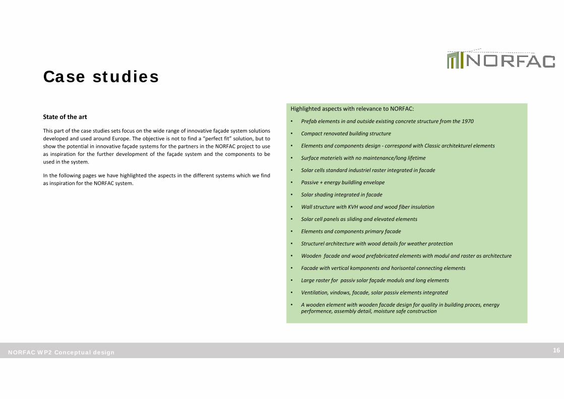
This part of the case studies sets focus on the wide range of innovative façade system solutionsdeveloped and used around Europe. The objective is not to find a “perfect fit” solution, but toshow the potential in innovative façade systems for the partners in the NORFAC project to useas inspiration for the further development of the façade system and the components to beused in the system.
In the following pages we have highlighted the aspects in the different systems which we findas inspiration for the NORFAC system.
NORFAC WP2 Conceptual design 16
Highlighted aspects with relevance to NORFAC:
• Prefab elements in and outside existing concrete structure from the 1970
• Compact renovated building structure
• Elements and components design ‐ correspond with Classic architekturel elements
• Surface materiels with no maintenance/long lifetime
• Solar cells standard industriel raster integrated in facade
• Passive + energy buildling envelope
• Solar shading integrated in facade
• Wall structure with KVH wood and wood fiber insulation
• Solar cell panels as sliding and elevated elements
• Elements and components primary facade
• Structurel architecture with wood details for weather protection
• Wooden facade and wood prefabricated elements with modul and raster as architecture
• Facade with vertical komponents and horisontal connecting elements
• Large raster for passiv solar façade moduls and long elements
• Ventilation, vindows, facade, solar passiv elements integrated
• A wooden element with wooden facade design for quality in building proces, energyperformence, assembly detail, moisture safe construction
Case studies
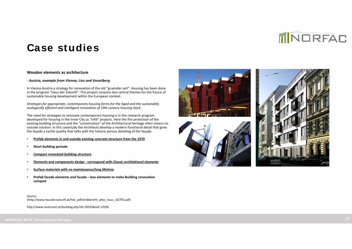
Wooden elements as architecture
‐ Austria, example from Vienna, Linz and Vorarlberg
In Vienna‐Austria a strategy for renovation of the old “gruender zeit”. Housing has been done in the program “Haus der Zukunft”. This project conjoins two central themes for the future of sustainable housing development within the European context:
Strategies for appropriate, contemporary housing forms for the Aged and the sustainable, ecologically efficient and intelligent renovation of 19th century housing stock.
The need for strategies to renovate contemporary housing is in this research program developed for housing in the Inner City as “infill” projects. Here the fire protection of the existing building structure and the “conservation” of the Architectural heritage often means no outside solution. In this casestudy the Architects develop a modern functional detail that gives the façade a tactile quality that talks with the historic porous detailing of the façade.
• Prefab elements in and outside existing concrete structure from the 1970
• Short building periode
• Compact renovated building structure
• Elements and components design ‐ correspond with Classic architekturel elements
• Surface materiels with no maintenance/long lifetime
• Prefab facade elements and facade – box elements to make Building renovation compact
Source:[http://www.hausderzukunft.at/hdz_pdf/endbericht_altes_haus_id2792.pdf]
http://www.nextroom.at/building.php?id=18335&sid=12026
NORFAC WP2 Conceptual design 17

Case studies
Active Stadt‐Haus
‐ Frankfurt, + energy building
The new building structure is south oriented. The structure is concrete elements with woodenfacade elements. The roof and facade is used for solar cells in order to make an passiv energy + building. The solar study and solar architecture of the building is an example of how passiv and aktiv elements of the Building envelope can be structured. The akustik and solar conditions, shade on the facade, raster of standard solar cells has been importent design parameter.
As a speciel topic the solar cells was regarded as material that can burn and therefore fire protection, distance etc. was part of the design proces of integration in the facade.
• Solar cells standard industriel raster integrated in facade
• Passive + energy buidling envelope
• Solar study with shade
• Wooden facade elements with acoustic improvement
• Solar shading integrated in facade
Source:[http://www.bmvi.de/SharedDocs/DE/Anlage/BauenUndWohnen/EHP/veranstaltung_01_download_05.pdf?__blob=publicationFile]
NORFAC WP2 Conceptual design 18

Case studies
Prefabricated solar wooden housing
– Decathleon 2014, a building system derived from renovation elements
The 2014 winner of the solar competition for universities world wide, has in the team a housing and wood element company. The structure of the buidlings is simple, made of KVH structurel wood with fiber wood insulation plates inbetween. The Solar unit house has af facade structured by elements like an atrium, solar shading with solar cells and large windows.
A model for Urban scaled building envelope folows the same design koncept. Solar cells can beelevated out so that they contribute to summer shadow on the facade. The materials used arewood, wood fiber insulation, plaster, organic colours and solar cell panels as elements in the facade.
• Wall structure with KVH wood and wood fiber insulation
• Quick assembly time
• Solar cell panels as sliding and elevated elements
• Atrium elements of the facade
• Elements and components primary facade
Source:[http://www.haus.rubner.com/it/servizi‐contatti/news‐eventi/rubner‐haus‐al‐solar‐decathlon‐europe‐2014/117‐2799.html]
[http://www.holzbau.rubner.com/de/produkte/wandelemente‐aus‐holz/32‐19.html]
NORFAC WP2 Conceptual design 19

Case studies
Constructed protective building design
‐ Austria – wooden building system and detailing of the Bausystem Kauffmann
The Vorarlberg company has experience in wood space modules and wooden detailing of the facade were the structure becomes a part of the architecturel quality and structurel woodprotection. Simple and elegant details, large vertical formats and a buidling prefab proces is not hidden away – but highlited as a architektural feature.
Staircase and acces to the open atelier appartments is placed outside the 4 story woodenstructure. The load carying elements for balconies and a public bridge to the park have thereown loadcaring structure.
• Structurel architecture with wood details for weather protection
• Wooden facade and wood prefabricated elements with modul and raster as architecture
• Facade with vertical komponents and horisontal connecting elements
Source:[http://www.nextroom.at/building.php?id=34031&sid=34392]
NORFAC WP2 Conceptual design 20

Case studies
Wooden elements with passiv solar integrated elements ‐ Linz solar Varpen
Existing social housing from 1957 build in homogenous concrete is renovated with prefabelements. Each element covers one Appartment and is produced with a structurel frame, facade elements mounted and windows. The facade facade consist of GAP elements that have an solar passiv heat effect on the facade with an U value effect, The U value is 0,082 W/m2K –total dimension element 290 mm (corresponding to 445 mm of mineral insulation). The ventilated glacing covers the 5 story facade. Some windows are installed in a frame with decentral ventilation for the room behind.
The modularity of the facade makes large GAP moduls possible so that assembly is quick and with less costs. Windows are mounted at the outside so that daylight is optimiced with lessshadow on the glass and the building form is kept reduced to the essentiel as the existingarchitecturel language is. The existing foundation is used for carying the load of the woodenelements. Existing Logien is clossed with 3 layer glacing.
• Large raster for passiv solar façade moduls and long elements
• Ventilation, vindows, facade, solar passiv elements integrated
• One surface glacing system also for new closing wall elements by logien
• Solar passiv dynamich U value , ca. 25% effect on all wall orientations.
Source:[http://www.hausderzukunft.at/hdz_pdf/071120_ws_sanierung_domenig.pdf]
NORFAC WP2 Conceptual design 21

Case studies
Smart TES Norwegian Wooden elements‐ Finish, façade system
This Project looks for essential quality parametres; moisture, building proces, energyperformance and assembly details. Framework conditions to different Building situations and climate is evaluated from a future climate perspective. A ricing in temperature leads to a highexposure of humidity and driving rain.
A 4 step design circle with the mentioned 4 topics is described – and a module is tested. National energy rules is replaced with passiv standard.
• A wooden element with wooden facade design for quality in:
• Building proces
• Energy performence
• Assembly detail
• Moisture safe construction
Source:[http://www.tesenergyfacade.com/downloads/smarttes_b4_Buildingphysics.pdf]
[www.tesenergyfacade.com]
NORFAC WP2 Conceptual design 22

Sustainability
NORFAC WP2 Conceptual design 23
The NORFAC facade system must be Sustainable in social, economical and environmental terms.
To substantiate the sustainability the facade element should be developed with a lifecycle perspective for the whole building, not only for construction but also for useand maintaniance. Like wise a holistic approch must be considered for the buildingarchitecture as a whole including the context and the social aspects of the building in the local society.
The three aspects of sustainability:
1. Social sustainability: Security, Health and Comfort
2. Environmental sustainability: Energy, Ecolocical and Life cycle.
3. Economical quality: Total economy , Robustness and Efficient use.
[Illustration: The NORFAC vision]

Social sustainability
NORFAC WP2 Conceptual design 24
Subset / Comfort and Resident account
In the following chapter social sustainability aspects for the NORFAC façade system are defined and specific focus areas area highlighted.
NORFAC shall contribute to secure a social sustainable environment, by offering a façade system open to designing for greater comfort and Social sustainability:
• Façade variations in design and materials.
• Integrated ventilation systems
• Larger windows for more daylight and out view.
NORFAC shall contribute to secure the flow of the refurbishment process, by offering a façade system based on a modularized prefabricated elements:
• Prefabrication in secure environments (factories).
• Seamless flow, short building periods and low nuisance impact.
• No resettlement. Residents to stay in their homes during the refurbishments.
[Illustration: The NORFAC vision]

Social sustainability
NORFAC WP2 Conceptual design 25
Quality in dwelling and living
Social quality covers a wide range of topics, many of which have parameters not possible for measures. Indoor climate and assess ability are well do regulated in the building regulations and national best practice standards. The experience oriented parameters like user control, functionality, interior design and good architecture, as quality of space, visibility opportunities, is also crucial for the wellbeing in the building.
Other aspects of social quality in the building it self, around the building and in a society perspective must be recognized and encouraged that these social qualities are there for everybody. The good housing complex with a good neighborhood will increased quality of life and it is important for social sustainability to create good conditions for well‐being and social cohesion. In a good and secure physical environment people are happier ‐ This shows in larger dwelling areas where the area and buildings are manageable and well‐lit.
To secure the social quality the frame for maintenance of these qualities must be created for the long perspective. The following highlighted perspectives should be considered:
• Wellbeing increases when the homes are functionally operating and can be adapted to the tenant's wishes for example temperature and décor.
• Larger windows support both the daylight intake in the dwellings and give overview to the outside.
• Out look and overview support security in the nearby areas, the building should have no backsides and no unattended areas.
• The sustainable community grows when residents have green common areas with room for accommodation and activities.
Source:[Bæredygtigt byggeri, Energi Styrelsen, April 2015]
[Illustration: bjerg arkitektur, Gadehavegård refurbishment]
NORFAC shall contribute to secure a better quality in dwelling:
• Larger windows for more daylight and better out view.
• Integrated openings and/or outdoor areas (as balconies).

Social sustainability
NORFAC WP2 Conceptual design 26
Indoor climate / Wellfare
A great part of the Social quality in a building depends on the wellbeing of the residents. The wellbeing presupposes that the physical comfort is present. For housings the depends in the indoor temperature, lack of draughts, air quality, acoustics, noise and access to daylight.
All of these parameters are messurable and the NORFAC should reach the values for “best practice” solutions for the indoor climate.
• Fresh air – ventilation solutions should be a integrated part of the facade system to support a better indoor climate in the dwellings. The solution can be both as integrated tubes or aggregates for automatic ventilations systems or fully integrated solutions as the ”Ventilations window”.
• Daylight – the façade system should support optimized daylight intake for the dwellings, such as expansion or redefinition of window areas and architectural freedom for daylight design and integrated solutions.
• Warm surfaces – the façade system should be highly insulated and eliminated thermal bridges so that the building envelope will remain safe and healthy for years with no draught and no moisture in cold surfaces and corners.
• Materials – the façade system must be made constructed by low emissions building materials to secure the indoor air quality in the dwelling and the health of the residents.
The increased comfort and well‐being as a result of a better indoor climate, will often have positive economic effect.
*DGNB SOC1.2 Indoor air quality (Office buildings 2014): Buildings with a TVOC‐concentration more than 3.000 μg/m³ or a formaldehyde concentration more than 100 μg/m³ can not be certified.
NORFAC shall contribute to secure a better indoor climate, by offering a façade system open to designing for greater indoor climate:
• Integrated ventilation systems.
• Larger windows for more daylight.
• Demand for use of low emissions building materials *

Social sustainability
NORFAC WP2 Conceptual design 27
Resident account
Major refurbishments are costly for the Housing companies and revolutionary for the residents having to live in a active building site or having to be resettled during the period of the refurbishment process.
Early inclusion of stakeholders and residents can be the start of a positive process for involvement, information and expectation vote. In the short perspective for the building site it is important to take into account the residents, neighbors and stakeholders in the area with regard to noise and dust pollution as well as vibration and heavy traffic for the building site and the difficulties for the surrounding traffic.
A criteria for the NORFAC system must be that it is possible for the residents to stay/live in their apartments during the facade refurbishment. The following positive aspects will be central in the process that the NORFAC system should emphasize.
• No expenses for resettlement during refurbishment
• Minimal discomfort for the Resident staying in their own home.
• Less planning and administration for the Housing Company.
To obtain these positive aspects in the refurbishment, it is necessary for the NORFAC system and the users of the system to plan the following aspects into the project:
• Resident; meetings and secure all information is given to the residents in time.
• Seamless flow; Short building period and minimal discomfort for the residents
• Low nuisance and dust impact
The list is not exhaustible.
NORFAC shall contribute to secure the flow of the refurbishment process, by offering a façade system based on a modularized prefabricated elements:
• Prefabrication in secure environments (factories).
• Seamless flow, short building periods and low nuisance impact.
• No resettlement. Residents to stay in their homes during the refurbishments.
Housing company ”know‐how”
In a beta‐case project the end user (Housing company) should be involved for the NORFAC project to gain Know‐How and User input for major facade refurbishments.
E.g.
Himmerland Boligselskab – User input
Alligsås – User/Resident analysis

Environmental sustainability
NORFAC WP2 Conceptual design 28
Subset / Low energy and sustainable facade system
In the following chapter low energy and sustainable aspects for the NOPRFAC façade system are defined and specific focus areas for environmental sustainability are highlighted.
NORFAC shall contribute to secure environmental sustainability, by setting demands for material and construction data to contain info usable for comparison and analysis for Sustainable Building standards :
• Global Warming potential data for BREEAM and DGNB assessment use.
• High amount (80%) of FSC certified wood used in the element
NORFAC shall contribute to secure environmental sustainability, by offering a façade system with high energy efficiency:
• Secure an acceptable indoor surface temperature by U‐value demands based on specifikclimate zone data
• Eliminate thermal bridges (Ψ < 0,01)
• Secure high level of air‐thightness in the facade system
NORFAC shall contribute to secure a environmental sustainability, by offering a façade system suited for integration of “Smart Active Systems”:
• Develop a system ready for installation of Integrated Smart Active Systems
[Illustration: The NORFAC vision]

Environmental sustainability
NORFAC WP2 Conceptual design 29
Sustainable Building standards
Sustainable buildings standards have been used since the 1990’s to develop and promotemethods and solutions for sustainable design, construction and management of buildings. InScandinavia all the three leading sustainable rating standards are used ‐ BREEAM, DGNB andLEED.
The three standards are alike in the matter that they all use certification by third partyverification check, as well as they all have their certification system adapted worldwide to therequirements in various regions and countries.
The main difference between the three is that LEED is a building standard focused theEcological aspect of building and building materials. As such LEED is a Green building standard,whereas BREEAM and DGNB is Sustainable building standards. BREEAM and DGNB is lifecyclebased and focus on the building “life” from planning to building to maintenance. DGNB andBREEAM are alike but the differ in the way they set up the parameters/criterias and in the waythey rate the points and score given.
BREEAM
BREEAM is originally started in Great Britain and now the longest established and most widelyused method of assessing, rating and certifying the sustainability of buildings in the world.Since 1990 more than 250.000 buildings spread across 50 countries, have been certified. TheSwedish and Norwegian Green Building Council operates BREEAM SE and BREEAM NORrespectively. BREEAM NOR is a country‐specific standard based on the BREEAM standard.Denmark have some BREEAM certified buildings but no official operator of the system.
DGNB
DGNB was started in Germany in 2008 and is one of the youngest sustainable buildingstandards. DGNB is a “2nd generation standard” based on the know‐how from BREEAM andLEED and with a wide range focus on the sustainability aspect. The Danish Green BuildingCouncil operates the Danish DGNB standard, which has been developed as a country specificstandard.
LEED
LEED is North American based but have spread around the world, as the leading Ecologicalbuilding standard. Swedish Green Building Council operates LEED SE.
Environmental sustainability
NORFAC WP2 Conceptual design 30
Global warming potential
The global warming potential (GWP value) shows how much a material could potentially contribute to the greenhouse effect. The GWP value can therefore be used as a quantifiable indicator for a building’s ecological performance. Likewise in the early phases it ca be used for simple comparison – lower GWP value equels a lower impact/contribution to the greenhouse effect.
In DGNB the GWP value is use in for the Criterion 1, to calculate the global warming potential for the life cycle of the entire building.
BREEAM NOR, Criterion Mat01, set demand for GWP in the Klimagassregnskab to support use of materials with a low GWP values compared to standard reference building materials. Material life and replacement are taken into consideration.
The GWB value should, beside being number for comparison, be worked into the Revit parameters. The amount of each material type in the façade element must be defined in kg (mass) / m2 façade. For façade with more than one material type, the % of each type must be defined as a calculation factor in the equation. Unit for the GWP value: [kg CO2 equiv. / kg material]
The material data can be documented through a EPD (Environmental Product Declaration) In the Revit parameters there should be links to the manufacturers EPD document on their homepage or to EPD or ESUCO databases, e.g.. www.epd‐norge.no.
NORFAC shall contribute to secure environmental sustainability, by setting demands for material and construction data to contain info usable for comparison and analysis for Sustainable Building standards :
• Global Warming potential data for BREEAM and DGNB assessment use.
• High amount (80%) of FSC certified wood used in the element
Wood certification
In both the BREEAM and DGNB system, the aim to promote use of timber and timber materials from sustainably managed forests to avoid destruction of forests around the world.
In DGNB, Criterion 8, the aim for the Projects is that 80% of the wood products used, is FCS or PEFC certified. This count for all wood used in the project. (walls, windows, stairs, flooring etc.)
BREEAM NOR criterion Mat05, set the same aim for 80% is pressent. This though is for ”resonable procurement” of all relevant materials in the projects. For wood in the construction, the FSC certificatet is acceptable vertification.
FSC and PEFC are certification programs for regulated and sustainable management of forests.FSC certification, if use of Subtropical or boreal woodPEFC certificate for central European wood

Environmental sustainability
NORFAC WP2 Conceptual design 31
Energy standards
The Passivhaus standard is known as the world leading low energy building standard. In both Sweden, Norway and Denmark the Passivhaus standard is well known and used in many projects – new build and refurbishment.The national building regulations (BR2015, TEK15, Boverket) has over the last years been regulated so that the ”extra effort” needed to reach the Passivhaus standard is eliminated‐
The low energy demand of a Passivhaus is based on a holistic approach to the building envelope performance and the optimization to solar gains.
For a case of NORFAC facade refurbishment it is not necessarily possible to integrate all Passivhaus aspects, since it is only the facade system being optimized. Therefor it is chosen to focus on the following aspects related to the facade components:
U‐value – construction : < 0,15 W/m2KU‐value – window : < 0,80 W/m2KThermal bridges: < 0,01 W/mKAir‐thigtness: < 0,5 h‐1
These values are from the international Passivhaus criteria list and figures only as maximum values. For a Scandinavian context only the Thermal bridges and Air thigtness values can be used. The U‐values for construction and windows has to be climate zone regulated to secure a sufficient indoor surface temperature. On the following page a climate‐zone regulated energy performance target values is displayed.
Indoor climate
The Passivhaus criteria's for the building envelope is based on building physics with the aim to secure a healthy and good indoor climate. With the necessary U‐values and eliminated thermal bridges the building envelope will remain safe and healthy for years with no draught and no moisture in cold surfaces and corners.
NORFAC shall contribute to secure a environmental sustainability, by offering a façade system with high energy efficiency:
• Secure an acceptable indoor surface temperature by U‐value demands based on specifik climate zone data
• Eleminate thermal bridges (Ψ < 0,01)
• Secure high level of air‐thightness in the facade system
Passiv solar energy gains
To minimize the energy demand for the buildings it is essential to design and optimize the facade for passive solar energy gains. The main window areas must be southern oriented, moderate areas should be northern oriented. When working on a existing building a total optimization for solar gains is not possible. The window areas should be defined based on both energy considerations and daylight studies as a integrated design.
When optimizing window areas it is also essential to design the solar shading strategy to avoid owe heating in the summer period. Solar shading can be design in many ways with all kind of systems and products. The solar shading coefficient should be Fc< 0,6 (minimum demand) or better down at Fc< 0,2 (target demand) for moveable solar shading on all windows NW to NE. (DGNB criteria 35)
Air thigtness
A high level of air tightness is essential for the Passivhaus standard, as air leakage results in both energy losses, draught and chances of moisture in the building envelope. Great attention to the design of the airtight layer and to the connection between building constructions is needed to create a sufficient level of air tightness. The airtight building envelope will also contribute to a higher efficiency of a automatic ventilation system.

Environmental sustainability
NORFAC WP2 Conceptual design 32
Climate zonesScandinavia has a large differing in climate zones, geographically dividing the region in threezones. PHPP calculations on reference buildings has shown the differing U‐ and Ψ‐values in therespektive zones to obtain the same building energy performance.
Each type of Base element, should be designed in three variations to fulfill the energyperformance demands for each Climate zone respectively.
For the user of NORFAC this will secure an acceptable indoor surface temperature, thermalcomfort and high energy performance, no matter where in Scandinavia the system is used.
Climate zone 1 Arctic
2 Cold
3 Moderat cold
CONSTRUCTION
Uconst. 0,08 – 0,06 W/m2K
0,10 – 0,08 W/m2K
0,12 – 0,09 W/m2K
WINDOW
Uwindow < 0,40W/m2K
< 0,60W/m2K
< 0,80W/m2K
Uglass < 0,35W/m2K
< 0,55 W/m2K
< 0,75W/m2K
THERMAL BRIDGES
Ψconst.< 0,01W/mK
< 0,01W/mK
< 0,01W/mK
Ψwindow< 0,04W/mK
< 0,04 W/mK
< 0,04W/mK
1
2
3
Source: PassivHaus Institute

Environmental sustainability
NORFAC WP2 Conceptual design 33
Smart Active Systems
Active energy systems plays a larger role in the modern sustainable world and in the whole aspect of green energy solutions , integrated facade solutions should be part of the architecture for future facade refurbishments.
The NORFAC facade system should embrace Active Energy Systems as integrated solutions in the facade system. Making the facade system suitable for many different types of active systems and make them assessable and flexible for the architects to design the future facades. For the suppliers parameters such as mounting systems and technical installations are essential for the active system to function in the facade. In the following list some of the active systems are defined and in short terms described in relation to the NORFAC project:
• Solar panels – the panels are often seen in a fixed grid, limiting the flexibility regarding size and combinations. A mounting system is necessary allowing ventilation behind the panels. Likewise installations should be considered integrated in the façade system.
• Ventilation – if working with central or decentralized automatic ventilation systems in the apartment building the NORFAC façade system should offer solutions for integrating tubes and/or aggregates in the façade system. This should allow to minimize the construction impact inside the building.
• Ventilations windows – can be used like ordinary windows in the facade system as a alternative to automatic ventilation solutions eliminating/reducing the impact of construction work inside the building.
• GAP – a facade system to store solar radiation heat, based on a multi‐layer façade elements a core in a honeycomb structure of cardboard, which acts differently as a climate‐regulating layer depending on the season and position of the sun. In summer, the honeycomb serves as a buffer, shading itself, and in the cold season it achieves an additional insulation effect.
• Solar shading – avoiding overheating during summer is one of the big challenges when designing highly insulated building. Shading solutions should be able to integrate in the façade system as either a flexible, movable or fixed solution.
• In‐Therm Climate Wall – interior wall solution for the facade system with insulation effect and evenly distributed heating surface for better efficiency and comfort.
The list is not exhaustible.
NORFAC shall contribute to secure a environmental sustainability, by offering a façade system suited for integration of “Smart Active Systems”:
• Develop a system ready for instalation of integrated Smart Active Systems
Current project partners (and future partners) should get involved with their solutions during the WP3 and WP4 to develop the technical solutions for e.g. mounting and installation solutions for their products in corporation with the development of the Alfa‐case (Energy flex office) and/ or Beta‐case projects in NORFAC.

Environmental sustainability
NORFAC WP2 Conceptual design 34
Optimizing Active systems
When applying Active systems to the façade it should be done in accordance to thelocal context and the specific situation for the single building.
The architectural design of the façade using the NORFAC façade system is open andshould in most ways be possible to use and design freely. To optimize the use andplacement of active systems on the facades it is important to run a proper analysis ofthe local context of the specific building. Not all active systems are sufficient on everyproject and the effectivity will also in many ways depend on where and how theelement is placed on the façade.
Several well known software solutions can be used for this task. E.g. for solar panels itis important to do shadow studios from other buildings, trees and even mountains.This ca be done in the Autodesk Revit (BIM) Likewise it is possible to measure the solarenergy reaching a specific area on the façade using Autodesk Vasari, a free digital tool.
The NORFAC project could as a service, provide the users with guidance to how theseanalysis are performed. Either with guidance to specific software or with guidance‐schemes showing recommendations for optimal effectivity.
Illustration_Shadow studio example: http://www.bmvi.de/
Illustration_Solar energy studio:

Environmental sustainability
NORFAC WP2 Conceptual design 35
Case – Gaia solar
Input from project partner.
3 principles of facade integrated solar panels:
• Raster grid – industrialized solar panel
• Sliding element – solar shading
• Window based element

Economical sustainability
NORFAC WP2 Conceptual design 36
Subset / Life Cycle Cost
With reference to the WP1 report chapter on Life Cycle Cost/“Total economy”, this section will in short highlight the focus areas of Economical sustainability for the NORFAC system.
NORFAC shall contribute to secure a economical sustainability, by offering a façade system with a great total economy, robustness and long life span:
• Use building component with long life and low maintainance.
• Building component with short life is replacable and/or easy for maintainance.
• Building components in exposed areas is created with high robustness.

Economical sustainability
NORFAC WP2 Conceptual design 37
Robustness
Robustness in construction, detailing and choose of materials is essential to secure a “healthy”and long lasting façade. The NORFAC system must promote satisfactory sollutions with focuson exposed areas of the building.
BREEAM NOR list of focus areas: (Breeam NOR mat07 – Robust constructions)
• Robust external wall construction (Skin material), up to 2 meters from terrain.
• Protection of exposed areas – external corners by transit zones
• Protection of exposed constructions parts against rain and other moisture load, bothduring construction and use phase.
• Use of materials which can withstand high moisture load in the parts of the constructionwhich are difficult to protect.
The list is not exhaustible
Life Cycle Costs (LCC)
Economical sustainability is in short terms about designing in relation to a holistic approach to quality and long‐term consequences for the chosen solutions. The following headlines should be seen as “benefits” for using a total economic approach in the NORFAC project and for refurbishment projects in general:
• To optimize the constructions costs for the building and/or building elements as well as the following operation costs.
• To ensure the value of the property over time by good quality, optimized functionality and great flexibility.
• To promote a economical appropriate and optimal approach to the construction and use of resources.
In a LCC perspective the elements of the facade should be detailed with a high level of robustness and the material chosen should be with the focus on ”Life Cycle Cost” instead of ”Cost for build”.
When calculating the LCC it is necessary to use dynamic calculations methods to ensure the most precise life cycle costs. Beside the construction costs; maintenance, replacement and operations costs have to be considered for the service life of the individual parts of the building components. The ”Present Value” (NPV) must be calculated according to the life cycle of the parts for the user/advisor to compare the different solutions.
In the WP1 chapter on this topic you will find a more detailed description on.
Today several calculations tools can be used for the LCC calculation. In the NORFAC project one tool should be chosen to ensure a comparability between the different façade solutions.
DGNB‐DK criteria 16: Building Related Life‐Cycle costs.
Source:[Introduction to LLC on buildings, Energi Styrelsen, April 2015]
NORFAC shall contribute to secure a economical sustainability, by offering a façade system with a great total economy, robustness and long life span:
• Use building component with long life and low maintainance.
• Building component with low life is replacable and/or easy for maintainance.
• Building components in exposed areas is created with high robustness.

Façade system design
NORFAC WP2 Conceptual design 38
Subset
This concept design for the NORFAC system will set the direction forhow demands a analysis can be combined for the architectual façadesolution. The concept will be tested, verified and developed in the WP3and WP4.
The concept is build on the wide range of sustainable parameterspresented in this report and based on á solution targeted the Alpha case– the Energy Flex Office. Upon this concept report the project partnersshould feel obligated to contribute to the further process of the Alpha-case and/or deepen their product knowledge according to therecommendations in this report.
Using the knowledge held by the project partners and uptain by user-input from the alpha and beta case, the NORFAC system should developin accordance with the NORFAC vision, to be a intelligent op façadesystem with high export potential.

Façade system design
NORFAC WP2 Conceptual design 39
Concept
The NORFAC facade systems is build upon a simple concept. The base of the system is a modular standard unit – later on mentioned as the base.
The base is not one defined type of facade construction. Rather the base element can be a variety of construction types, differing in structural and insulation materials and build up.
On this NORFAC base a great variations of solutions for Skins, Windows and Smart active elements can be combined in various ways to create the final façade.
Though the parameters and guidelines presented in this report, must be complied with to secure a ”red line” through out the NORFAC system. Further more the parameters will be useful as comparable on different aspects for the future users to decide the NORFAC combination best fit for their project.
For the user the NORFAC will provide a flexible and secure façade system ‐ designed to create freedom in the architectural approach together with high‐end sustainable solutions.

Façade system design
NORFAC WP2 Conceptual design 40
Refurbishment
The NORFAC facade systems is build upon a simple concept. The base of the system should be designed to be useable I several refurbishment situations, depending on the existing building situation and/or construction:
• Exteriour refurbishment
• Swift refurbishment
• Interiour resfurbishment

Façade system design
NORFAC WP2 Conceptual design 41
NORFAC Base
The NORFAC facade systems is build upon a simple concept. The base of the system is a modular standard unit – later on mentioned as the base.
The base is not one defined type of facade construction. Rather the base element can be a variety of construction types, differing in structural and insulation materials and build up.
Supplier
As the NORFAC is an open façade system it should be possible for different type of manufacturers/suppliers to create new base element to be part of the system. The new base type should be developed in accordance to a set of fixed demands, based on the demands for “best practice” described in this report. When the solution(‐s) live up to the expectations, it will made available through the NORFAC‐platform for the users to choose for their refurbishment project.
The NORFAC group (or system owner) should define a set up for the verification and approval procedure for new suppliers and/or new base types to be included in the NORFAC system.

Façade system design
NORFAC WP2 Conceptual design 42
Smart Active Element – Skin ‐Windows
For the user the NORFAC will provide a flexible and secure façade system ‐ designed to create freedom in the architectural approach together with high‐end sustainable solutions.
Upon the base element of the NORFAC system a flexible layer of solutions should be available for the user to design a façade in accordance to the wanted architecture, materiality and technical solutions. The great variations of solutions for Skins, Windowsand Smart active elements is based on partners products fitted to the NORFAC system. New solutions must comply with parameters and guidelines from the WP2 report to secure a flexible and high quality façade system.
The façade solutions should be seen as a secondary layer to the base, since the lifecycle of the skin, active elements and windows will be significantly shorter than the lifecycle of the base element. The base is protected from exterior impact and will therefor last as long as 40‐100 years, depended on the type of element and materials. On the other hand the skin and windows might only last 20‐40 years and the technical solutions even shorter. Therefore the façade system should take into account the possibility to perform replacement and/or maintains in the design of the build‐in and mounting solutions.
Supplier
The great variations of solutions for Skins, Windows and Smart active elements to the NORFAC system must all comply with parameters and guidelines from the WP2 report to secure a flexible and high quality façade system. Further more the supplier should provide detail drawings for mounting, build‐in and connections – to ensure the best practice use in the NORFAC system.
The NORFAC group (or system owner) should define a set up for the verification and approval procedure for new suppliers and/or new base types to be included in the NORFAC system.
Façade system design
NORFAC WP2 Conceptual design 43
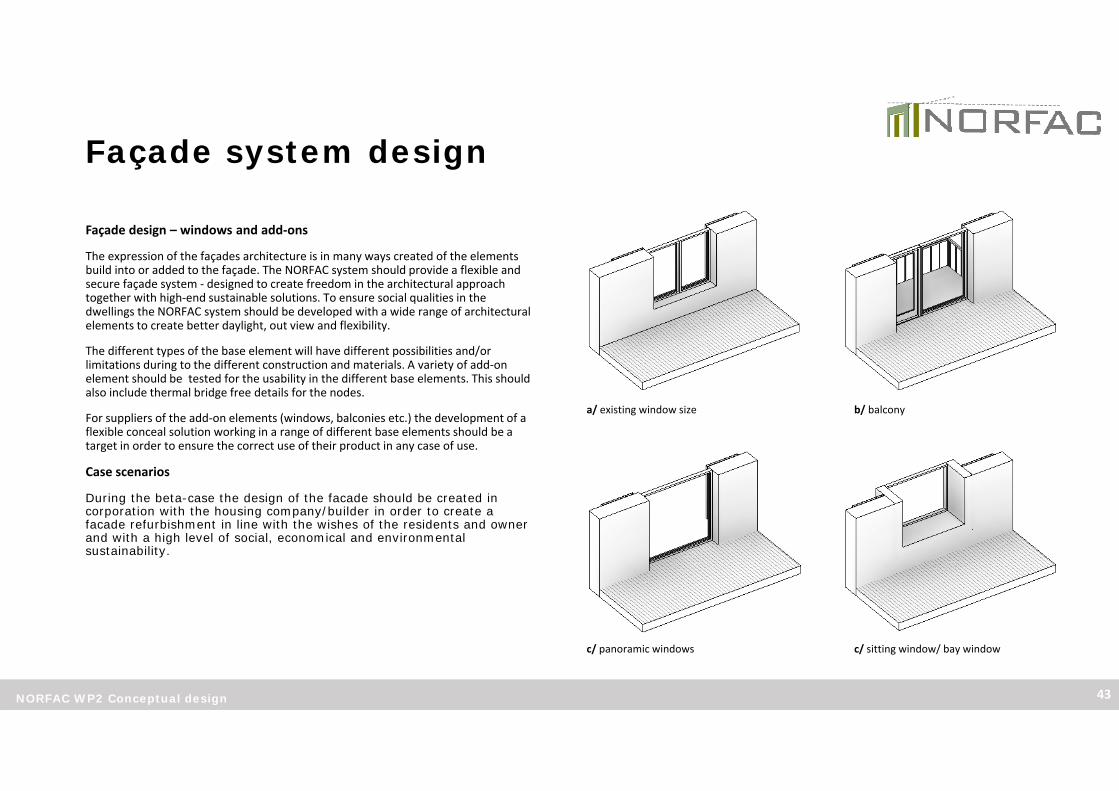
Façade design – windows and add‐ons
The expression of the façades architecture is in many ways created of the elements build into or added to the façade. The NORFAC system should provide a flexible and secure façade system ‐ designed to create freedom in the architectural approach together with high‐end sustainable solutions. To ensure social qualities in the dwellings the NORFAC system should be developed with a wide range of architectural elements to create better daylight, out view and flexibility.
The different types of the base element will have different possibilities and/or limitations during to the different construction and materials. A variety of add‐on element should be tested for the usability in the different base elements. This should also include thermal bridge free details for the nodes.
For suppliers of the add‐on elements (windows, balconies etc.) the development of a flexible conceal solution working in a range of different base elements should be a target in order to ensure the correct use of their product in any case of use.
Case scenarios
During the beta-case the design of the facade should be created in corporation with the housing company/builder in order to create a facade refurbishment in line with the wishes of the residents and owner and with a high level of social, economical and environmental sustainability.
a/ existing window size b/ balcony
c/ panoramic windows c/ sitting window/ bay window

Façade system design
NORFAC WP2 Conceptual design 44
Daylight
To define and test the window amount for the alpha‐case in accordance to best practice , the façade design should be tested and developed using a daylight visualizing tool.
This design tool is very efficient in the early stages of the façade design –not only to analyze for sufficient daylight, but also to optimize the window area and position of windows. As shown in the test‐case illustration, high windows from the floor up, will provide the room with daylight further into the room.

Façade system design
NORFAC WP2 Conceptual design 45
Nodes ‐ best practice detailing
When developing the NORFAC façade system for the alpha project there should be paid great attention to the nodes and the detailing in accordance to the WP2 report recommendations for air‐thigtness, thermal bridge free construction and robust solutions. Best practice solutions for the nodes in the façade is essential to ensure a high quality long‐lasting façade system.
The development of the best practice solutions for the nodes should involve the relevant project partners concerning technical, manufacturing and build ability. The following list highlights the main nodes to be resolved for the case.
1. Roof – connection to existing roof construction
2. Terrain – node at terrain – new plinth or brackets.
3. Base connection – Vertical connection – air tightness, thermal bridge
4. Base connection – Horizontal connection – air tightness, thermal bridge
5. Window insert – build in, air tightness + thermal bridges
6. Smart element – mounting, installations, raster grid
7. Skin – mounting
8. Building corners (not illustrated) – connections around corners.
9. Balconies (not illustrated) – mounting and stability
The list is not exhaustible.
1/ 3/
5/
4/
2/
6/
7/

Façade system design
NORFAC WP2 Conceptual design 46
Process – Resident impact
To ensure minimal resident impact during the façade refurbisment, there should be seen to best practice from MT Højgaard (project partner) as well as input from the beta‐case owner and other relevant
To minimize the impact on the residents during the refurbishment, methods of construction process, involving great level of information and the residents staying in their home during the process should be highlighted.
MT Højgaard
Contractor experince from finalized projects.
Himmerland Boligselskab and Allingsås
Housing company experince from finalized projects.

Façade system design
NORFAC WP2 Conceptual design 47
ALPHA Case – Energy Flex office
To test the NORFAC facade system in real life the Energy Flex Office at Teknologisk Institut in Taastrup, Denmark, has been decided to use as “alpha case”. In the following pages we will show the start of the design and detailing process for the project, planed to be continued through out the WP3. The case specific project will involve several of the project partners and will be based on the concept presented in this report, leading to a test‐façade manufactured and mounted on the Energy Flex Office building.
Energy Flex Office – base, modular grid
As seen in the drawing on the right, the Energy Flex Office is placed on the top floor of the building (orange). The first step in the refurbishment process is to define the existing conditions and lay down the overall strategy for the refurbishment.
In the development of the “NORFAC base, type 1” is must be considered how to segregate the façade in accordance with the most efficient production procedure for the specific base type. The most efficient segregation is based on several parameters which differs in accordance to the base type specifications:
• Existing constructions – structural concerns
• Local conditions – building site restrictions, space demand for handling the large elements
• Production and transport – element size, weight and handling
• Design – windows and façade• Energy Flex Office• Vertical segregation, example• Horizontal segregation, example

Façade system design
NORFAC WP2 Conceptual design 48
Energy Flex Office ‐ test module
The NORFAC facade systems is tested in an existing existing situation/ construction.
• Exteriour refurbishment with integrated ventilation module, components, façade and active elements integrated.

Façade system design
NORFAC WP2 Conceptual design 49
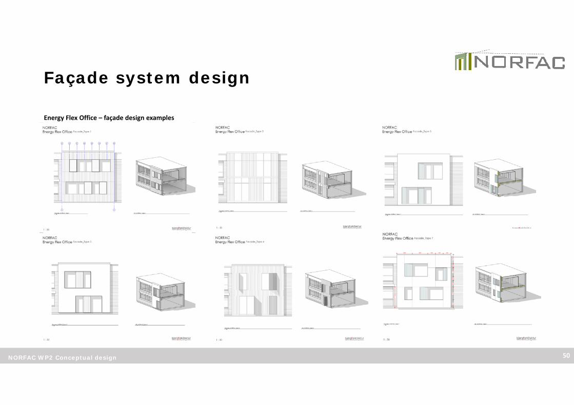
Energy Flex Office – façade design
The collection of design proposals on next page shows a wide range of façade designs for the project. In corporation with the project partners the design should be developed in accordance with product dimensions, raster‐grids and the modules for the base element production. This will define and structure the modular system for the NORFAC system.
For the Alpha‐case the project will as a starting point involve the following project partners and products:
• ClimatWinTechniq – Ventilations windows
• Gaia Solar – Solar Panels
• Royal Træ – Wood cladding
• BN Teknik – Interour wall with heating
During the development of the project this constellation might change.
o SkinWood cladding
o Smart active elementSolar panel
o Smart active elementInterior wall
o BaseType 1
Façade system design
NORFAC WP2 Conceptual design 50
Energy Flex Office – façade design examples

Façade system design
NORFAC WP2 Conceptual design 51
Energy Flex Office – Visualization
Façade system design
NORFAC WP2 Conceptual design 52
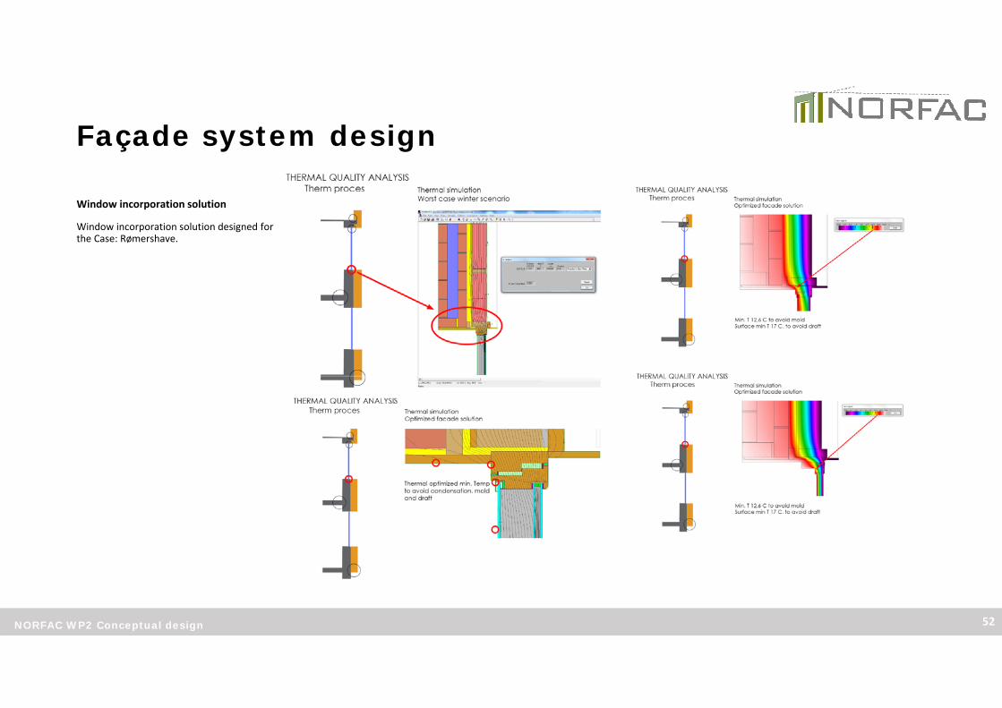
Window incorporation solution
Window incorporation solution designed for the Case: Rømershave.

Façade system design
NORFAC WP2 Conceptual design 53
BETA Case – Himmerland Boligselskab, Aalborg
For a retrofitting of an existing 2 story building a new façade renovation is planned. The NORFAC system can here be tested in a Beta‐ case.
The existing structure is not profoundly changed. The appartments are devided intodifferent sizes. The facade modules can be vertical ands siced to max size to reduceprice.
The facade can be lay out in modules that makes it possible also to integrate aktive elements. In this case the primary element is the NORFAC basic element though with costcalculation.
Preliminary meeting have been held and a Workshop has been arranged. The outcome from these meeting and the process in between will lead to the development of the Beta case pro
More information on the Kildeparken project can be found at:
www.kildeparken2020.dk

Façade system design
NORFAC WP2 Conceptual design 54
[Illustration_metode for assesment and evaluation_example[http://www.tesenergyfacade.com/downloads/smarttes_b4_Buildingphysics.pdf]
NORFAC design method
During the development of the NORFAC system it should be set as a target to create a clear method for the design process from the existing building to a finalized NORFAC refurbishment.
The method should like the example to the right, highlight the framework conditions and show the steps to ensure a best practices façade solution, using the NORFAC system to embrace the process .

BIM concept
NORFAC WP2 Conceptual design 55
Subset
This WP2 report defines the “outlines” for the web‐based BIM‐platform as a promotion and service‐page for future NORFAC‐users to compare and design a façade‐refurbishment with the NORFAC system.
Likewise the BIM concept contains a Revit system familie based parameter layout containing the data input and output according to the sustainability aspects defined in this report.
The concept for the NORFAC BIM should be seen as an “Offline” BIM concept, that should be developed by the WP5 leaders during the WP3 and WP4 in cooperation with the WP2 leaders and other project partners.
Illustration_BIM proces: http://www.bexelconsulting.com/

BIM concept
NORFAC WP2 Conceptual design 56
Web Platform
The NORFAC BIM platform is set to be a web‐based solution providing information and services for the different type of users ‐ housing companies, suppliers , contractors and advisors. By making the NORFAC Platform web‐based it will be easily assessable for the users and easy to update and maintain for the system owner.
Overall the platform should have a “two‐entry” approach, allowing the platform to both serve a sales‐service for the end‐users (housing companies) as weel as serving as a professional tool for the users (advisors, contractors and suppliers).
Web‐based BIM platform
End Userhousing company
Useradvisor
Usercontractor
Usersupplier
NORFAC visioninfo
“Guide book”Refurbishment “A,b,c”“From idea to final”
BenefitsResidents impactTime and planningSustainability‐ Energy‐ Indoor climate
ReferencesProject database
Advisors contactList of registered advisors
Contractor contactList of registered contractors
NORFAC visioninfo
BIMSystem families downl.Guide
ArchitectureDesign‐ Flexibility List of Suppliers‐ Base elements‐ Skins‐ Smart active systems‐Windows and build‐onsSustainability‐ Values‐ Comparison‐ Advise for best practiceEnergy‐ Values‐ Comparison‐ Advise for best practice
NORFAC visioninfo
BIMPlanningPriceGuide
How to buildGuide
MaintenanceData sheets collection for Facility management
SuppliersList of suppliers and manufactures
NORFAC visioninfo
BIMDemands for syst. fam.Guide
How to be supplierDemandsGuide
SuppliersList of Norfac partners, advisors, contractors and suppliers.

BIM concept
NORFAC WP2 Conceptual design 57
End User
This part of the platform should act as a sales and service page for the housing companies interested in the NORFAC solution or already working with a NORFAC project. The setup must be easy assessable, define the NORFAC vision and underline the benefits of choosing the NORFAC façade system for their next refurbishment project. Focus must be on the three way sustainable approach (Social, Environmental and Economical) and the fact that the NORFAC system is as much a service as a product –ensuring better planning and process with less resident impact during construction.
The housing companies are professional building owners, but the residents representation will also have a vote when refurbishments project have to be accepted. A well defined “guide book” describing a NORFAC refurbishment from A to Z, should be a part of the assessable material to convince and ensure the residents in the decision process. Likewise maintenance data for the housing companies facility management should be provided as datasheets or links to the manufactures.
When possible, executed project references should be made available on the platform. Project data, process pictures and a well described “project report” including interviews with the housing company and the residents should be part of the material.
Web‐based BIM platform
End Userhousing company
Useradvisor
Usercontractor
Usersupplier
NORFAC visioninfo
“Guide book”Refurbishment “A,b,c”“From idea to final”
BenefitsResidents impactTime and planningSustainability‐ Energy‐ Indoor climate
ReferencesProject database
Advisors contactList of registered advisors
Contractor contactList of registered contractors

BIM concept
NORFAC WP2 Conceptual design 58
User ‐ Advisor
This part of the platform should act as a tool for advisors working with the NORFAC system. The setup should allow for the advisors to assess and compare the solutions within the NORFAC system. All elements of the system should be available as Revit system families, free to download, containing the data defined for the NORFAC system. This topic is described further in the following pages.
The NORFAC platform should give a overview and make it easy for the advisor to compare the different façade solutions according to the sustainable parameters defined in the WP2 report – as a system database all solutions should be available but at the same time there should be an innovative flow in filtering the different solutions to match the specific project and the advisors preferences (materials, design, sustainability etc.) as well as preset definitions (Climate zone) to ensure the right façade solution.
To ensure that the potential of the NORFAC system is unfolded, there should be guides, recommendations and simple design tools available. These help‐tools should help the users work smarter using the NORFAC system – guiding them through the use of the Revit system families, as well as ensuring them with best practice solutions regarding sustainability, energy and build ability. For the active systems simple “tools” should be presented for helping a efficient facade design – e.g. sensible placement of solar panels with regard to orientation and local conditions.
NORFACWeb‐based BIM platform
End Userhousing company
Useradvisor
Usercontractor
Usersupplier
NORFAC visioninfo
BIMSystem families downl.Guide
ArchitectureDesign‐ Flexibility List of Suppliers‐ Base elements‐ Skins‐ Smart active systems‐Windows and build‐onsSustainability‐ Values‐ Comparison‐ Advise for best practiceEnergy‐ Values‐ Comparison‐ Advise for best practice
Comparison example:
Base, type A
Energy W/m
GWP kg CO2 eqv.
Cert. Matr. %
LCC factor
Base, type B
Energy W/m
GWP kg CO2 eqv.
Cert. Matr. %
LCC factorExample: Web‐layout – with easy assess to the different parts of the NORFAC system.

BIM concept
NORFAC WP2 Conceptual design 59
User ‐ Contractor
This part of the platform should act as a service page for contractors interested in or using the NORFAC system. There should be easy access to all the different elements of the system supplying the contractor with information on the manufactures or suppliers as well as links to the constructions guides and maintenance data for facility management.
The NORFAC BIM is able to provide the contractor with data on amounts and measures to price calculation and planning directly from the 3D BIM model created of the project. There could be created guidelines to ensure the correct data and the correct use of the BIM data.
Input from project partners should be part of the development.
User ‐ Supplier
This part of the platform should act as support and information for current and future suppliers to the NORFAC system. Describing the vision and demand for the quality of the elements and the demands for BIM to be included into the NORFAC.
Input from project partners should be part of the development.
Web‐based BIM platform
End Userhousing company
Useradvisor
Usercontractor
Usersupplier
NORFAC visioninfo
BIMPlanningPriceGuide
How to buildGuide
MaintenanceData sheets collection for Facility management
SuppliersList of suppliers and manufactures
NORFAC visioninfo
BIMDemands for syst. fam.Guide
How to be supplierDemandsGuide
SuppliersList of Norfac partners, advisors, contractors and suppliers.

BIM concept
NORFAC WP2 Conceptual design 60
BIM Platform ‐ USER
BIM is one of the corner stones in the present and modern building industry, making it possible to add information/data to the 3d building model to be used when analyzing energy and sustainability, calculating price, planning the project and used for facility management.
In the NORFAC project BIM is an essential part and the connecting element between the services provided and the final product (façade system).When designing a new façade for a refurbishment project the architects should be able to go to the NORFAC web‐platform, entering a BIM database containing all the façade bases, skins and other element as “Revit system families”. These system families are free to download and directly useable in the Autodesk Revit model for the current project. The system families should be built around the same frame‐work ensuring the quality, the data level as well as the model ability of the NORFAC BIM.
Modeldata can be included in the system families I different ways. Type specific data such as energy and sustainability data, should be directly placed in the model data for Revit to calculate project specific values directly in the 3d model. Other type of information such as supplier info and maintenance guides should be included in the system families as links. These links should lead the user to the specific data‐sheet in the NORFAC web‐platform where the latest/updated datasheet always should be available. This will make it possible for the supplier to update the datasheets with no need to send out new updated system families.
The level of constructive detailing in the Revit system families should be considered regarding the file‐size of the Revit family. To much detailing means a heavy file slowing down work in the 3d Model. Highly detailed construction details could instead be included as links, leading the user to the NORFAC web platform and a collection of 2d detail drawing for the main nodes in the different NORFAC solutions. The value of best practice solutions is essential for the NORFAC system to unfold the potential, with thought through details raising the value of the system as a whole. Example: BIM‐Object delivers Revit System families for all types of suppliers. Their web‐
platform allows the user to download the objects and use them in their 3D models.

BIM concept
NORFAC WP2 Conceptual design 61
3d – design and detailing
As part of the NORFAC BIM, the workflow and use of BIM in‐between the different actors in the project should be as simple as possible. When designing the façade the process should be smooth and flexible, when detailing the project more specific information on best practice is needed. To ensure the right information level is present at the right time the development of the “BIM‐architecture” should also involve corporation with partners representing the different parts in the BIM project phases.
3d to 4d and 5d
To make the most of the potential in 3d BIM modelling, the data must be useable in a 4d and 5 d process.
• 4d BIM: Using volumes and amount data from the 3d model to calculate precise construction prices
• 5d BIM: Using 3d model data for the planning of the construction process, enabling to plan a precise timetable for the construction in early stages of the project.
As part of the development of the BIM set up for the NORFAC project. The usability and workflow will be tested during the WP5. This will ensure a “smart” and functional service that will optimize the work during façade design, detailing and carrying out construction. This development will be undertaken by the WP5 leader in cooperation with the WP2 and Wp4 leaders, using the software available for the partners.The process will be iterative more than linear – using trial and error, setting goals/demands for the 4/5d output and working backwards to the design phase.

BIM concept
NORFAC WP2 Conceptual design 62
Revit System families
The 3D Bim System family or ”object” (Revit) can contain data specific for the elements chosen for the project. These data must be implementet in all the Revit system families for the NORFAC facade system. The parameters listed on the next pages should be seen as a minimum. During the development of the Bim platform these parameters should be tested and added to by input from the project partners/leaders for WP2, WP3, WP4 and WP5.
For additionary Bim System families (windows and other components) it is important for the supplier to deliver the same parameters and data, as these adds value to the NORFAC system.
4D and 5D Bim parameters must be defined in close coorporation between the project partners/leaders for WP2, WP3, WP4 and WP5
Glossary:
Model output:
Geometric data, area, volume, orientation etc. based on the actual 3D BIM project.
Type data:
Input data based on product documentation from the supplier for the specific Revit system family – e.g. NORFAC baseelement.
Preset data:
Object data common for all NORFAC elements, preset for the NORFAC system – e.g. climatdata values and commonexisting wall types.
Calculation:
Calculations made in the Revit system family based on the geometric data for the specific 3D BIM project and the typedata for the chosen Revit system family. The result from the calculations can be used for comparison between façadesolutions and used for input into Sustainability documentation (DGNB, BREEAM)

BIM concept
NORFAC WP2 Conceptual design 63
ENERGY PARAMETERS IN REVIT OBJECT PROPERTIES
Data input:Transmissions loss, W/m2K (U‐value) type dataLine loss (A), W/mK (Perimeter, terrain) type dataLine loss (B), W/mK (Perimeter, roof) type dataLine loss (C), W/mK (inserts, windows etc.) type dataAirtightness, n50 (…) type data
Model output, energy losses:Transmission, kWh/y (U‐value * Area * Gt) calculationLine loss, terrain, kWh/y (length (A) * Line loss (A) * Gt) calculationLine loss, roof, kWh/y (length (A) * Line loss (B) * Gt) calculationLine loss, Windows, kWh/y (length (B) * Line loss (C) * Gt) calculationVentilations loss, n50 (…) calculationTotal energy loss (sum) calculation
SUSTAINABILITY PARAMETERS IN THE REVIT OBJECT PROPERTIES
Data input:Kg/CO2 equivalent / m2 (Breeam; A1‐A4) type data
(DGNB; A1‐A3, B1, B4, B6, C3, C4, D) type data# material A, % (% of volume pr. m2 element) type data# material B, % (% of volume pr. m2 element) type data# material C, % (% of volume pr. m2 element) type dataOR pr. Element type data
EPD (LINK to certificate) type dataWood, % with FSC certf. (% of volume) type data
(LINK to certificate) type data
Model output, comparison:
Kg/CO2 equivalent, total (Breeam; …) * Area calculation
(DGNB; …) * Area calculation
PROPERTIES FOR REVIT OBJECT ELEMENTS
Modeldata from the BIM model:Area, m2. (excl. Windows and doors) model output
Volume, m3. (excl. Windows and doors) model output
Length (A), m. (in plane) model output
Length (B), m. (inserts) model output
Element data input from Supplier:Element number Serial number, QR type data
Classification (CCS/SfB ) type data
Code (Sigma, Navisworks etc.) type data
Weight, kg (kg/m2 (type data) * Area) calculation
Gt, (location, Climate zone 1, 2 or 3) Scroll menu, preset data
Existing wall type (U‐value dependence) Scroll menu, preset data
Supplier(s) (Link to homepage) type data
Maintenance info (Link to homepage) type data
4D AND 5D BIM PARAMETERS
Price, data input:
Kr. / m2 (including… ) type data(excluding… ‐ project specific) type data
Planning, VDC data input:
Type code, etc. (… ) type data

BIM concept
NORFAC WP2 Conceptual design 64
Case – ClimaWinTechniq
Short describtion of the development of the ”ClimateWintechniq” Revit windowsystem family. The coorporation between Bjerg arkitektur, VIA and ClimaWinTechasweel as the technical describtion.
It is recomended that other project partners use this case as inspiration for making a system family for their own products.
Input to the report when the system family is finished.

Links and references
NORFAC WP2 Conceptual design 65

Editing author:
Søren Riis Dietz
Bjerg arkitektur a/s
Nikolaj Skole
Bjerg arkitektur a/s
NORFAC WP2 Conceptual design 66