NORDHAVN 41, Pocket Cruiser
23
Hull Optimization Study NORDHAVN 41, Pocket Cruiser NORDHAVN 41, Pocket Cruiser NORDHAVN 41, Pocket Cruiser NORDHAVN 41, Pocket Cruiser Project Project Project Project 7660 7660 7660 7660 Vripack International Naval Architects B.V. Zwolsmanweg 16 8606 KC SNEEK The Netherlands
Transcript of NORDHAVN 41, Pocket Cruiser

Hull Optimization Study
NORDHAVN 41, Pocket CruiserNORDHAVN 41, Pocket CruiserNORDHAVN 41, Pocket CruiserNORDHAVN 41, Pocket Cruiser
Project Project Project Project 7660766076607660
Vripack International Naval Architects B.V. Zwolsmanweg 16 8606 KC SNEEK The Netherlands

7660-0655 - Hull optimization study.doc Page 3
PrefacePrefacePrefacePreface For the Nordhavn 41, Pocket Cruiser displacement motor yacht, a hull optimisation study was performed. The objective of this study was to investigate and optimize the following:
• Wave pattern along the hull • Wave resistance • Flow lines along the hull • Dynamic trim angle
This optimisation study was performed by means of full scale Computer Fluid Dynamics (CFD). This report contains the description of the optimization process as well as the results and conclusions. Sneek, 01 March 2019
ExExExExecutive Summaryecutive Summaryecutive Summaryecutive Summary Careful examination of the CFD calculation of the original Nordhavn 41, has shown a wave pattern with a pronounced bow wave, quite some twist in the stream traces near the forefoot to midship, a relative large stern wave, and a secondary wave pattern caused by the forward shoulder. This hull was optimized by a reduction of the transom area, forward shoulder, prismatic coefficient and waterline entry angle. The volume of the forefoot was increased, as well as the transom beam. These modifications have reduced wave making resistance by 13%, 10% and 7% at 6, 7 and 8 knots. A trim wedge of 15 degrees gives a total reduction of 10%, 20% and 15% at 6, 7 and 8 knots.

7660-0655 - Hull optimization study.doc Page 4

7660-0655 - Hull optimization study.doc Page 5
Contents
GENERAL INFORMATION GENERAL INFORMATION GENERAL INFORMATION GENERAL INFORMATION OF THE YACHTOF THE YACHTOF THE YACHTOF THE YACHT 6666
INPUTINPUTINPUTINPUT 7777
GRID & COMPUTATION SGRID & COMPUTATION SGRID & COMPUTATION SGRID & COMPUTATION SETUPETUPETUPETUP 8888
GRID ON HULL SHAPE ....................................................................................................................................................................................... 8
GRID ON WATER SURFACE .............................................................................................................................................................................. 9
OPTIMOPTIMOPTIMOPTIMIZATION PROCESSIZATION PROCESSIZATION PROCESSIZATION PROCESS 11111111
RESULTS ................................................................................................................................................................................................................. 11 WAVE PROFILES ALONG THE HULL ........................................................................................................................................................... 12 DYNAMIC TRIM .................................................................................................................................................................................................. 21
CONCLUSIONSCONCLUSIONSCONCLUSIONSCONCLUSIONS 23232323
7660-0655 - Hull optimization study.doc Page 6
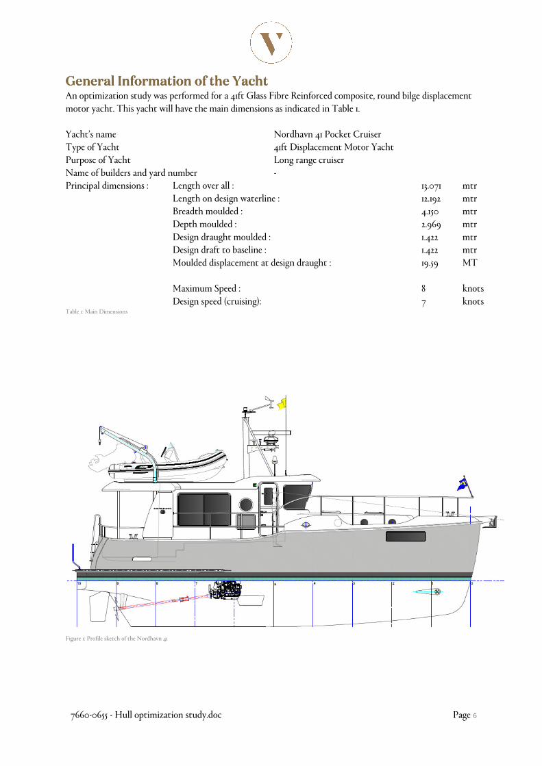
General InGeneral InGeneral InGeneral Information of the formation of the formation of the formation of the YachtYachtYachtYacht An optimization study was performed for a 41ft Glass Fibre Reinforced composite, round bilge displacement motor yacht. This yacht will have the main dimensions as indicated in Table 1. Yacht’s name Nordhavn 41 Pocket Cruiser Type of Yacht 41ft Displacement Motor Yacht Purpose of Yacht Long range cruiser Name of builders and yard number - Principal dimensions : Length over all : 13.071 mtr Length on design waterline : 12.192 mtr Breadth moulded : 4.150 mtr Depth moulded : 2.969 mtr Design draught moulded : 1.422 mtr Design draft to baseline : 1.422 mtr Moulded displacement at design draught : 19.59 MT Maximum Speed : 8 knots Design speed (cruising): 7 knots Table 1: Main Dimensions
Figure 1: Profile sketch of the Nordhavn 41
7660-0655 - Hull optimization study.doc Page 7
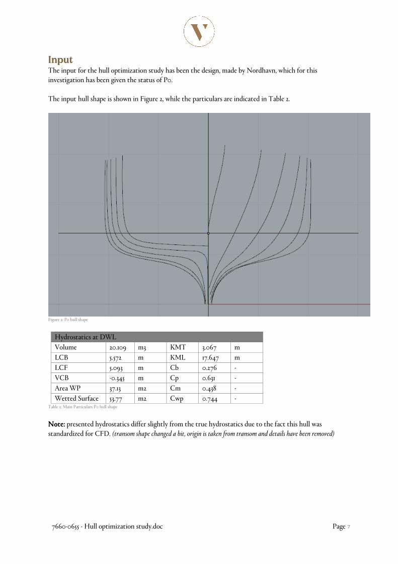
InputInputInputInput The input for the hull optimization study has been the design, made by Nordhavn, which for this investigation has been given the status of P0. The input hull shape is shown in Figure 2, while the particulars are indicated in Table 2.
Figure 2: P0 hull shape
Hydrostatics at DWL
Volume 20.109 m3 KMT 3.067 m
LCB 5.572 m KML 17.647 m
LCF 5.093 m Cb 0.276 -
VCB -0.345 m Cp 0.631 -
Area WP 37.13 m2 Cm 0.438 -
Wetted Surface 53.77 m2 Cwp 0.744 - Table 2: Main Particulars P0 hull shape
Note:Note:Note:Note: presented hydrostatics differ slightly from the true hydrostatics due to the fact this hull was standardized for CFD. (transom shape changed a bit, origin is taken from transom and details have been removed)
7660-0655 - Hull optimization study.doc Page 8
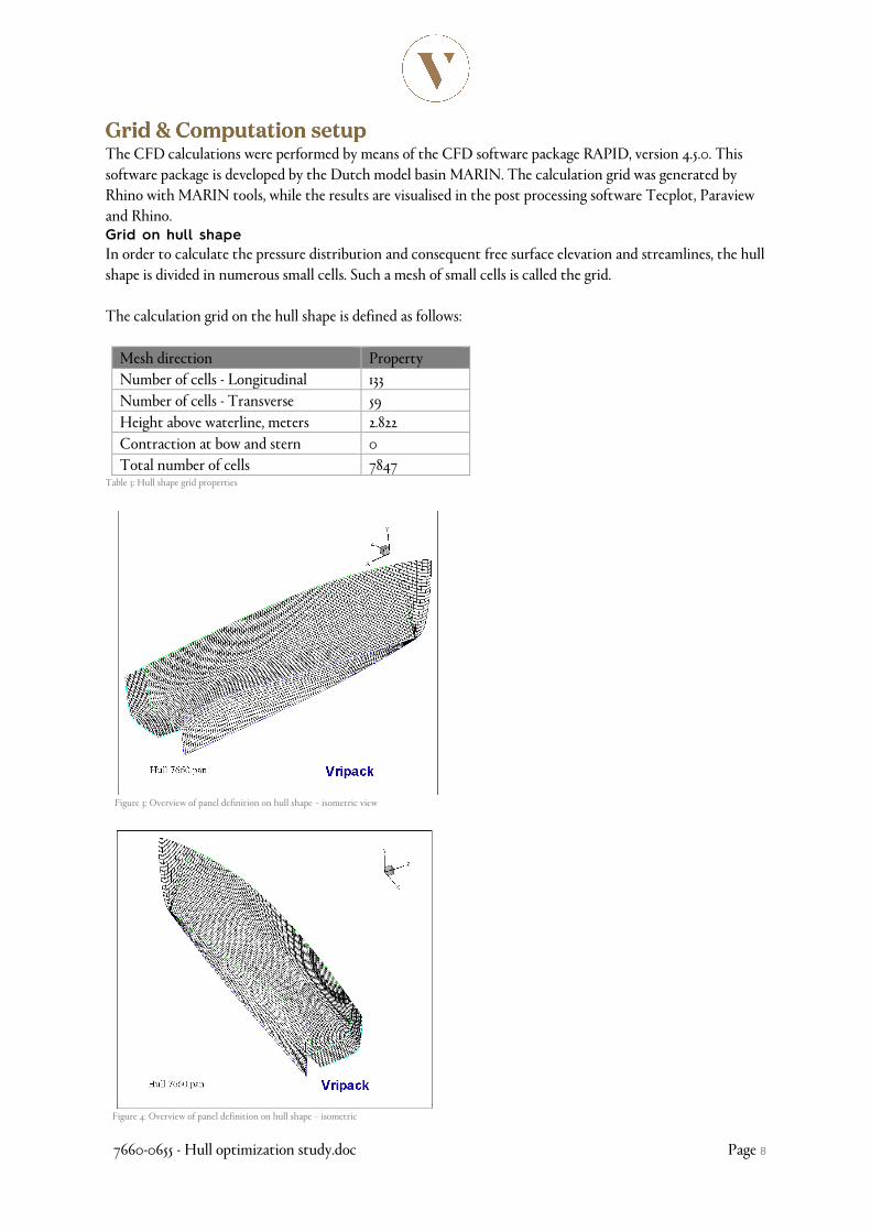
Grid & Computation setupGrid & Computation setupGrid & Computation setupGrid & Computation setup The CFD calculations were performed by means of the CFD software package RAPID, version 4.5.0. This software package is developed by the Dutch model basin MARIN. The calculation grid was generated by Rhino with MARIN tools, while the results are visualised in the post processing software Tecplot, Paraview and Rhino. Grid on hull shape
In order to calculate the pressure distribution and consequent free surface elevation and streamlines, the hull shape is divided in numerous small cells. Such a mesh of small cells is called the grid. The calculation grid on the hull shape is defined as follows:
Mesh direction Property
Number of cells - Longitudinal 133
Number of cells - Transverse 59
Height above waterline, meters 2.822
Contraction at bow and stern 0
Total number of cells 7847 Table 3: Hull shape grid properties
Figure 3: Overview of panel definition on hull shape – isometric view
Figure 4: Overview of panel definition on hull shape – isometric

7660-0655 - Hull optimization study.doc Page 9
Grid on water surface
In addition to the grid on the hull shape, the free surface (water surface) is defined by means of a mesh as well. The calculation grid on the free surface is defined as follows: 6 knots:
Mesh direction Property
Number of panels along hull 20
Number of cells – Transverse (behind Transom) 6
Free surface elevation, meter 0.2 Table 4: Free surface mesh properties for 10 knots of speed
Figure 5: Free Surface panel definition for 6 knots of speed
7 knots:
Mesh direction Property
Number of panels along hull 20
Number of cells – Transverse (behind Transom) 6
Free surface elevation, meter 0.324 Table 5: Free surface mesh properties for 7 knots of speed
Figure 6: Free Surface panel definition for 7 knots of speed

7660-0655 - Hull optimization study.doc Page 10
8 knots:
Mesh direction Property
Number of panels along hull 20
Number of cells – Transverse (behind Transom) 6
Free surface elevation, meter 0.2 Table 6: Free surface mesh properties
Figure 7: Free Surface panel definition for 8 knots of speed

7660-0655 - Hull optimization study.doc Page 11
Optimization ProcOptimization ProcOptimization ProcOptimization Processessessess In order to get maximum results, the optimization process after runs of the P0 hull was split into several steps:
1. (P1) Optimize prismatic coefficient (longitudinal distribution of underwater volume); 2. (P2) Optimize streamlines along the hull; 3. (P3) Optimize trim wedge
4. Figure 8: First optimization, P0 to P1
5. Figure 9: Final hull shape, P1 to P2
Results
The above indicated process resulted in the optimized hull shape as indicated in the figures below. These figures show the initial and optimized hull shapes, the pressure plots, stream traces and wave elevations and wave pattern along the hull for the initial and optimized hull shape. In addition, the reduction in wave resistance is shown which was achieved as a result of the optimization process.
7660-0655 - Hull optimization study.doc Page 12
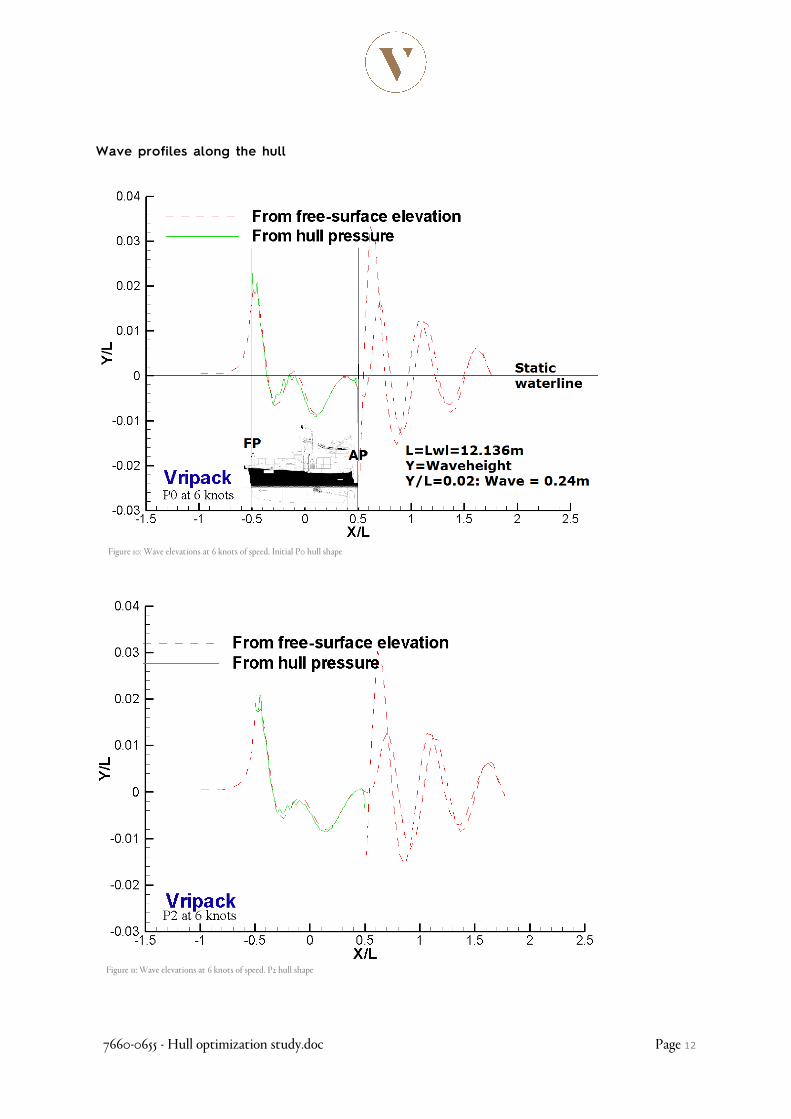
Wave profiles along the hull
Figure 10: Wave elevations at 6 knots of speed. Initial P0 hull shape
Figure 11: Wave elevations at 6 knots of speed. P2 hull shape

7660-0655 - Hull optimization study.doc Page 13
Figure 12: Wave elevations at 7 knots of speed. Initial P0 hull shape
Figure 13: Wave elevations at 7 knots of speed. P2 hull shape

7660-0655 - Hull optimization study.doc Page 14
Figure 14: Wave elevations at 8 knots of speed. Initial P0 hull shape
Figure 15: Wave elevations at 8 knots of speed. Initial P2 hull shape

7660-0655 - Hull optimization study.doc Page 15
Figure 16: Pressure plot and streamtraces at 6 knots of speed for initial P0 hull shape
Figure 17: Pressure plot and streamtraces at 6 knots of speed for optimized P2 hull shape

7660-0655 - Hull optimization study.doc Page 16
Figure 18: Pressure plot and streamtraces at 7 knots of speed for initial P0 hull shape
Figure 19: Pressure plot and streamtraces at 7 knots of speed for optimized P2 hull shape

7660-0655 - Hull optimization study.doc Page 17
Figure 20: Pressure plot and streamtraces at 8 knots of speed for initial P0 hull shape
Figure 21: Pressure plot and streamtraces at 8 knots of speed for optimized P2 hull shape

7660-0655 - Hull optimization study.doc Page 18
Figure 22: Wave pattern at 6 knots for initial P0 hull shape
Figure 23: Wave pattern at 6 knots for optimized P2 hull shape

7660-0655 - Hull optimization study.doc Page 19
Figure 24: Wave pattern at 7 knots for initial P0 hull shape
Figure 25: Wave pattern at 7 knots for optimized P2 hull shape

7660-0655 - Hull optimization study.doc Page 20
Figure 26: Wave pattern at 8 knots for initial P0 hull shape
Figure 27: Wave pattern at 8 knots for optimized P2 hull shape
7660-0655 - Hull optimization study.doc Page 21
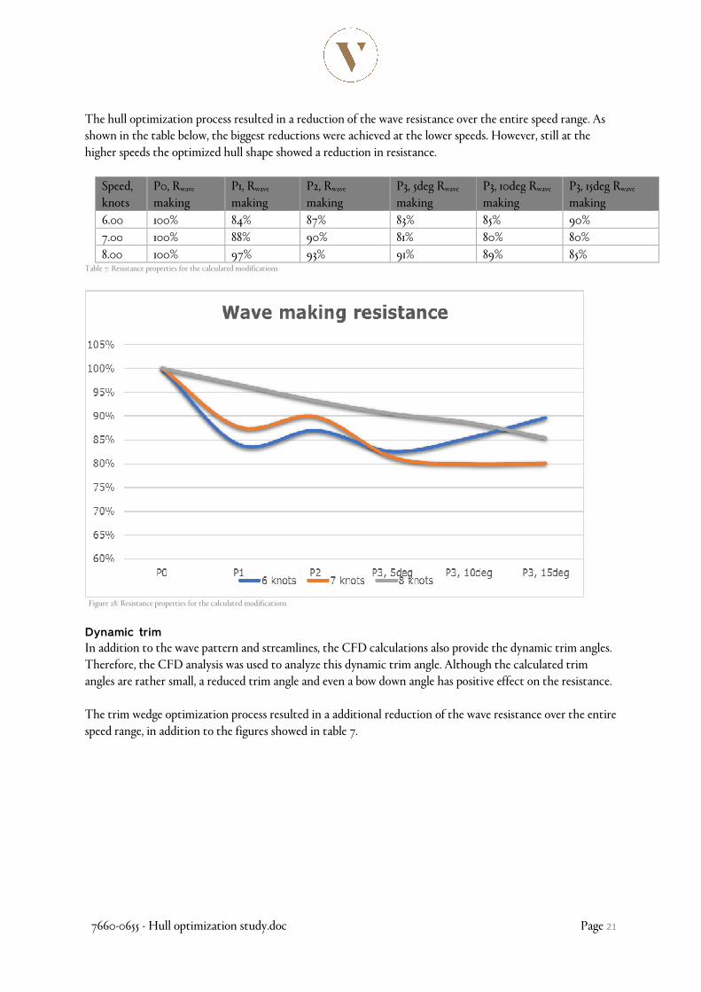
The hull optimization process resulted in a reduction of the wave resistance over the entire speed range. As shown in the table below, the biggest reductions were achieved at the lower speeds. However, still at the higher speeds the optimized hull shape showed a reduction in resistance.
Speed, knots
P0, Rwave making
P1, Rwave making
P2, Rwave making
P3, 5deg Rwave making
P3, 10deg Rwave
making P3, 15deg Rwave
making
6.00 100% 84% 87% 83% 85% 90%
7.00 100% 88% 90% 81% 80% 80%
8.00 100% 97% 93% 91% 89% 85% Table 7: Resistance properties for the calculated modifications
Figure 28: Resistance properties for the calculated modifications
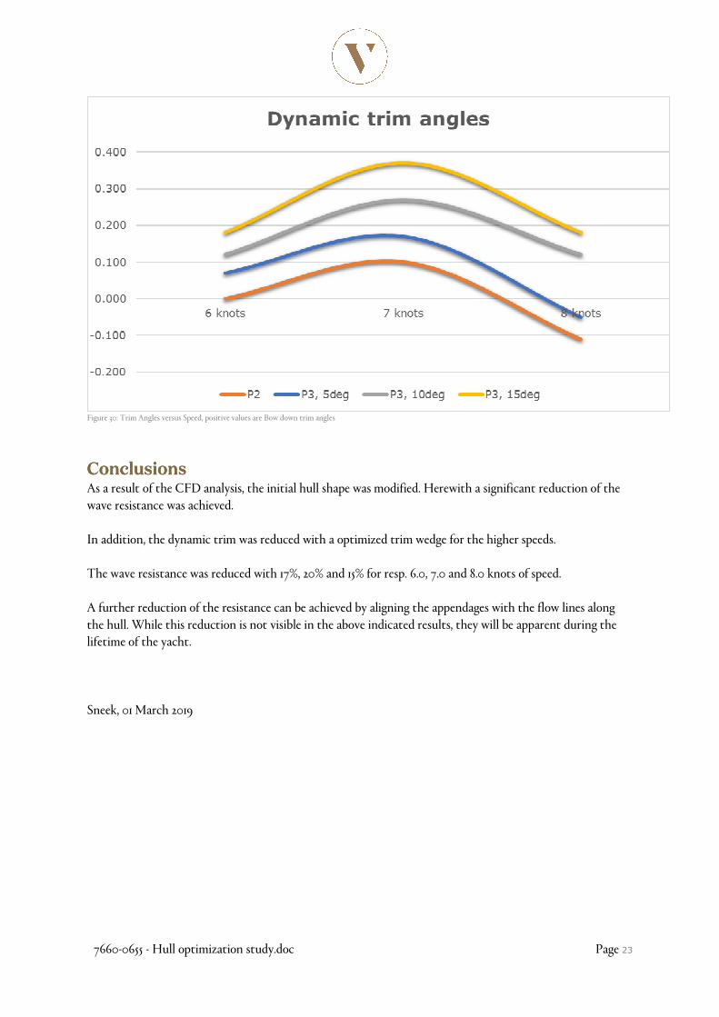
Dynamic trim
In addition to the wave pattern and streamlines, the CFD calculations also provide the dynamic trim angles. Therefore, the CFD analysis was used to analyze this dynamic trim angle. Although the calculated trim angles are rather small, a reduced trim angle and even a bow down angle has positive effect on the resistance. The trim wedge optimization process resulted in a additional reduction of the wave resistance over the entire speed range, in addition to the figures showed in table 7.

7660-0655 - Hull optimization study.doc Page 22
Figure 29: Trim Wedge configuration. Left; Lines Plan P3, 15degree trimwedge, Right; CFD model.
The dynamic trim angles of the initial and optimized hull shape are shown for various speeds in the table below.
Speed, knots P0, Trim P1, Trim P2, Trim P3,5 Trim P3,10 Trim P3,15 Trim
6.00 0.100 aft 0.070 aft 0.000 0.070 fwd 0.120 fwd 0.180 fwd
7.00 0.030 fwd 0.040 aft 0.100 fwd 0.170 fwd 0.270 fwd 0.370 fwd
8.00 0.200 aft 0.400 aft 0.110 aft 0.050 aft 0.120 fwd 0.180 fwd Table 8: Dynamic trim angles
Figure 28 shows the resistance curves for the calculated range of trim wedges. This figure clearly shows the resistance reduction for the various trim wedge configurations versus the hull without a trim wedge, for the higher speeds. At the mid speed the effect of the trim wedge on the resistance is neutral, for the low speed there is a negative effect of a trim wedge on the resistance. The design objective for this optimization study is to reduce resistance and increase range at the mid and higher speeds, therefore a trim wedge of 10 to 15 degrees is advised.
7660-0655 - Hull optimization study.doc Page 23
Figure 30: Trim Angles versus Speed, positive values are Bow down trim angles
ConclusionsConclusionsConclusionsConclusions As a result of the CFD analysis, the initial hull shape was modified. Herewith a significant reduction of the wave resistance was achieved. In addition, the dynamic trim was reduced with a optimized trim wedge for the higher speeds. The wave resistance was reduced with 17%, 20% and 15% for resp. 6.0, 7.0 and 8.0 knots of speed. A further reduction of the resistance can be achieved by aligning the appendages with the flow lines along the hull. While this reduction is not visible in the above indicated results, they will be apparent during the lifetime of the yacht. Sneek, 01 March 2019