NONSYMBOLIC LOGIC (BRIEFLY and PARTIALLY) …iconicmath.com/mypdfs/nonsymbolic-partial.040118.pdf1...
50
1 NONSYMBOLIC LOGIC (BRIEFLY and PARTIALLY) William Bricken March 2002 -- Condensed, abstracted, cut-and-pasted January 2004 SOME SECTIONS CONSIST OF DEVELOPMENT NOTES. MOST SECTIONS ARE PARTIAL AND NOT COMPLETE. Elementary logic addresses the ANDs, IFs, ORs and NOTs embedded in our spoken and written language. When formulated as an exhaustive tabulation, elementary logic is truth tables. When formalized in an inferential system, it is propositional calculus. When formalized in an equational system, it is Boolean algebra. And when formalized in a spatial system of containers, it is boundary logic. Each of these systems of logic includes a set of rules or transformations which permit logical forms to change structure without changing meaning. Truth tables require brute-force evaluation of every possible set of variable bindings. The primary operator in an inferential system is implication, usually expressed as modus ponens. In equational systems, the familiar match-and-substitute permits equals to be exchanged for equals. In boundary logic, the primary operations are void-substitution (erasure or deletion) and transparency (virtual erasure). LOGIC FORMALISM Throughout the evolution of axiomatic logic, mathematicians have attempted to reduce and simplify the basis set of assumptions necessary to define the semantics of logic. Logicians cast this basis within a framework of inference; the central connective in a logical axiom is implication. In contrast, algebraists cast the basis within an equational framework; the central connective is equality. The difference between the two approaches is that logical inference is one-directional, that A implies B does not mean that B implies A. Logical implication is asymmetric. As a consequence, the processes of logical deduction and proof must accumulate inferences as a database of facts implied by a set of premises. In contrast, the mechanisms of algebra, which we know from seventh grade algebra of numbers, allow the current state of a computation to be carried along within an equation. Algebraic deduction is bidirectional, using substitution of equals for equals as a primary computational mechanism. A third axiomatic approach is to use recursive function theory, to define processes in terms of a base case and an inductive, recursive case. Function theory assumes an equational context.
Transcript of NONSYMBOLIC LOGIC (BRIEFLY and PARTIALLY) …iconicmath.com/mypdfs/nonsymbolic-partial.040118.pdf1...

1
NONSYMBOLIC LOGIC (BRIEFLY and PARTIALLY)
William Bricken
March 2002 -- Condensed, abstracted, cut-and-pasted January 2004
SOME SECTIONS CONSIST OF DEVELOPMENT NOTES. MOST SECTIONS ARE PARTIAL AND
NOT COMPLETE.
Elementary logic addresses the ANDs, IFs, ORs and NOTs embedded in our spoken
and written language. When formulated as an exhaustive tabulation,
elementary logic is truth tables. When formalized in an inferential system,
it is propositional calculus. When formalized in an equational system, it is
Boolean algebra. And when formalized in a spatial system of containers, it
is boundary logic.
Each of these systems of logic includes a set of rules or transformations
which permit logical forms to change structure without changing meaning.
Truth tables require brute-force evaluation of every possible set of variable
bindings. The primary operator in an inferential system is implication,
usually expressed as modus ponens. In equational systems, the familiar
match-and-substitute permits equals to be exchanged for equals. In boundary
logic, the primary operations are void-substitution (erasure or deletion) and
transparency (virtual erasure).
LOGIC FORMALISM
Throughout the evolution of axiomatic logic, mathematicians have attempted to
reduce and simplify the basis set of assumptions necessary to define the
semantics of logic. Logicians cast this basis within a framework of
inference; the central connective in a logical axiom is implication. In
contrast, algebraists cast the basis within an equational framework; the
central connective is equality. The difference between the two approaches is
that logical inference is one-directional, that A implies B does not mean
that B implies A. Logical implication is asymmetric. As a consequence, the
processes of logical deduction and proof must accumulate inferences as a
database of facts implied by a set of premises. In contrast, the mechanisms
of algebra, which we know from seventh grade algebra of numbers, allow the
current state of a computation to be carried along within an equation.
Algebraic deduction is bidirectional, using substitution of equals for equals
as a primary computational mechanism.
A third axiomatic approach is to use recursive function theory, to define
processes in terms of a base case and an inductive, recursive case. Function
theory assumes an equational context.

2
The degree of representational and computational power embodied in each of
these axiomatic approaches varies, with implicational logic being the most
clumsy for computation, and recursion being the most elegant.
Independent of the axiomatic approach, the representation of logical form
also strongly effects the power and clarity of axioms. Lakatos, in Proofs
and Refutations, shows that the evolution of a mathematical concept is
dynamic, with emphasis falling at one time on the axioms themselves, and at
another times on the definitions which identify the data structures that the
axioms refer to.

3
SYMBOLIC NOTATIONS
Formal Logic
Several sets of notation for the operations of primary logic have been
introduced by the various founders of symbolic logic. Generally each
invented his own notation, Thus, negation may be
Language Peano Hilbert Variations Boolean Boundary
_
NOT P ~P P ¬P -P P' (P)
We will select a set of symbols with convenient typography herein, since
indeed, in contrast to diagrammatic notations, typographical symbols are
intended to be typographically convenient.
Connective Symbol
NOT ¬
AND &
OR v
IMPLIES ->
IF AND ONLY IF =
Implicational Basis
TRUE p -> p
FALSE F
NOT p -> F
AND (p -> (q -> F)) -> F
OR (p -> F) -> q
IMPLIES p -> q
IF AND ONLY IF ((p -> q) -> ((q -> p) -> F)) -> F
Sheffer Stroke
Both NAND and NOR are single connective bases for primary logic, although
technically they require one ground token, such as FALSE, in symbolic
systems. The symbol for NAND is called stroke, |, and is named after Sheffer
although it was first formalized by Peirce. The symbol for NOR is called
dagger, †, also accredited to Sheffer.

4
Connective Stroke Dagger
TRUE TRUE FALSE†FALSE
FALSE TRUE|TRUE FALSE
NOT p|p p†p
AND (p|q)|(p|q) (p†p)†(q†q)
OR (p|p)|(q|q) (p†q)†(p†q)
IMPLIES p|(q|q) ((p†p)†q)†((p†p)†q)
Combinators
Proposed first by Schonfinkel in 1924, and refined later by others, this
system demonstrates that variables are not a necessary part of logic.
<<implications of no variables>>
Here is the SKI calculus, introduced by Curry, Feys, and Craig in 1958. It is
the same as Schonfinkel's calculus.
Ix = x
Kxy = x
Sfgx = fx(gx)
Note that I is redundant, since
I = SKK
Polish Notation
Developed by Lukasiewicz, this system requires no brackets, Each capital
letter operator takes an exact number of arguments which follow.
Connective Polish Symbolic Polish
NOT Np ¬p
AND Kpq &pq
OR Apq vpq
IMPLIES Cpq ->pq
IF AND ONLY IF Epq =pq

5
AXIOMATIC SYSTEMS
FREGE'S AXIOMS
Frege was the first to formalize logic. He presented his work in his own
diagrammatic form, Frege diagrams. It is very difficult to find mention of
his notation without consulting is original manuscripts in German. In the
nearly universal process of transcribing Frege diagrams to symbolic logic,
the power of Frege's diagrammatic thinking has been almost completely lost.
Frege provided six axioms for simple logic. They are not independent. The
third "axiom" is a theorem of the first two. The fourth, fifth, and sixth
can all be reduced to a single axiom:
(¬p->¬q)->(q->p)
The first three define the stroke of implication, the next three define
negation. Frege's notation builds in a basis of {NOT, IMPLIES} since it has
not other representational forms.
1) a -> (b -> a)
2) (c -> (b -> a)) -> ((c -> b) -> (c -> a))
3) (c -> (b -> a)) -> (b -> (c -> a))
4) (b -> a) -> (¬a -> ¬b)
5) ¬¬a -> a
6) a -> ¬¬a
LUKASIEWICZ' AXIOMS OF INFERENCE
Lukasiewicz produced perhaps the most elegant set of axioms of inference in
symbolic notation.
1) (p->q)->((q->r)->(p->r))
2) p->(¬p->q)
3) (¬p->p)->p
1) is transitivity of implication
2) is consequentia mirabilis -- Stoics
3) is self-contradictory conjunction -- John Duns the Scot

6
NICOD'S AXIOM FOR BOOLEAN ALGEBRA
In 1917, Nicod proposed a single axiom for primary logic. It is always
possible to cast any set of axioms into one single form, simply by combining
them by conjunction. The difficulty is then to find patterns which match the
usually complex result. That is, one always then decomposes the single axiom
into a more convenient group of theorems.
Nicod's formalization, based on the Sheffer stroke (NAND):
[p|(q|r)]|([t|(t|t)]|{(s|q)|[(p|s)|(p|s)]})
[p|(q|r)]| {(s|q)|[(p|s)|(p|s)]})
or
[p|(q|r)]|{(t->t)|[(s|q)->(p|s)]}
where p->q = [(p|(q|q)]
The variety of delimiters above is solely to distinguish application nesting.
HUNTINGTON'S AXIOMS FOR BOOLEAN ALGEBRA
Huntington's algebraic system was the first to unite logic with group theory.
+ (OR) * (AND)
Commutativity a+b = b+a ab = ba
Identity a+00 = a a11 = a
Complement a+a' = 11 aa' = 00
Distribution a+bc = (a+b)*(a+c) a*(b+c) = ab+ac
Below, the parens notation of boundary logic and the symbolic notation of
conventional inferential logic are compared to Boolean Algebra.
Parens
Commutativity implicit in unstructured space
Identity a = a a = a
Complement a (a) = ( ) ((a) a) =
Distribution a ((b)(c)) = ((a b)(a c))
((a)(b c)) = ((a)(b)) ((a)(c))

7
Natural Logic
+ (OR) * (AND)
Commutativity (a v b) = (b v a) (a & b) = (b & a)
Identity (a v F) = a (a & T) = a
Complement (a v ¬a) = T (a & ¬a) = F
Distribution (a v (b & c)) = ((a v b) & (a v c))
(a & (b v c)) = ((a & b) v (a & c))
Inferential Logic
Boolean algebra is quite awkward in pure inferential logic. Even adding NOT
and maintaining the equality sign, the resulting expressions are unfamiliar.
Without algebraic equality, each equation would convert into the form
¬((X -> Y) -> ¬(Y -> X))
+ (OR) * (AND)
Commutativity (¬a -> b) = (¬b -> a) ¬(a -> ¬b) = ¬(b -> ¬a)
Identity (¬a -> F) = a ¬(a -> ¬T) = a
Complement a -> a = T ¬(a' -> a') = F
Distribution
¬a -> ¬(b -> ¬c) = ¬((¬a -> b) -> ¬(¬a -> c))
¬(a -> ¬(¬b -> c)) = (a -> ¬b) -> ¬(a -> ¬c)

8
SPENCER-BROWN'S ARITHMETIC AND ALGEBRAIC AXIOMS
In Laws of Form (1967), Spencer-Brown made the unique contribution of
formalizing the arithmetic of logic.
( )( ) = ( ) CALLING
(( )) = CROSSING
(a (a)) = POSITION
a ((b)(c)) = ((a b)(a c)) TRANSPOSITION
Position is AND-complement in Huntington's system, while transposition is
distribution.
KAUFFMAN'S SINGLE AXIOM
((a b)(a (b))) = a
Kauffman elegantly shows the relationships between inference, logical
tautology and logical arithmetic in the following two dimensional diagram,
for which both rows and columns are combined in space to create new
structures.
( a b ) ( a (b)) = (a)
((a) b ) ((a)(b)) = ((a))
= = =
( b ) ( (b)) = ( )
BRICKEN'S COMPUTATIONAL RULES
(A ( )) = VOID OCCLUSION
A {B A} = A {B} PERVASION

9
The third equation that characterizes Boundary Logic is
((A)) = A INVOLUTION
which can also be derived as a theorem given the definition of equality.
X = Y =def= (X Y) ((X)(Y))
by substituting
X = ((A)) and Y = A
To express Pervasion in symbolic notations, we must use a shallow form of the
rule, and apply it repeatedly, spreading the rule over both axioms and proof.
A (B A) = A (B) SHALLOW PERVASION
Computational Rules Expressed as a Recursive Function
Propositional logic, aka formal deduction, aka rationality, can be expressed
as a single recursive function. The base case is Void Occlusion:
({A} ()) = <void> Base case
The inferential case is Deep Pervasion:
{A} {B {A}} = {A} {B} Inductive case
The base case uses parens, ( ), as its language to express logical forms, and
establishes the class of void equivalent forms.
The inductive case uses braces called deeparens, { }, as schema that refer to
the set of all possible parens forms. The curly braces are necessary in
order to represent a variable as having both an outside and an inside.
All Boolean forms can be constructed using this equation constructively.
Should one begin with <void>, the base case permits all False forms to be
generated. Should one begin with a mark, ( ), a functional variety of the
base case, Dominion, permits all True forms to be generated.
{A} ( ) = ( ) Base case, Dominion
Forms are semantically equal simply because they are constructed from the
same base, ( ) or <void>.

10
DIAGRAMMATIC LOGIC
HISTORICAL EVOLUTION
In general, the original explorers of the concepts of logic formulated their
understandings in spatial, rather than symbolic form. Symbolic logic is
relatively new, introduced first by Boole in 1854. In the latter half of the
19th century, during the rigorous formalization of logic, Venn, Peirce and
Frege all developed inherently spatial representations. Russell's symbolic
notation was adopted universally after around 1910, since the spatial forms
were considered too clumsy to work with.
Aristotle's Square of Opposition
Aristotle wanted to create a classification of declarative language,
presumably to enhance the veracity of Greek debate.
The Square of Opposition was the first spatial display of logical concepts:
Affirm Deny
Universal A Every _ is _. EE No _ is _.
Particular I Some _ is _. OO Some _ is not _.
In terms of parens:
Affirm Deny
Universal (_) _ ((_) _)
Particular ((_)(_)) (_)(_)
Syllogistic Figures
B is the minor term
M is the middle term
C is the major term
_ is one of the AEIO forms from the Square of Opposition. B, M and C fill in
the blanks in the particular AEIO form.

11
Figure First Second Third Fourth
Major premise M_C C_M M_C C_M
Minor premise B_M B_M M_B M_B
Conclusion B_C B_C B_C B_C
The moods of the figure are the particular choice of the AEIO form in the
figure's "shape".
Euler Diagrams
The first use of closed planar circles to represent syllogistic relations
probably occurred in the 16th century [Lull, Ars Magna]. In the eighteenth
century, Euler proposed a system which used spatial enclosure to express the
syllogistic figures. At that time, logic was solely syllogistic reasoning.
There is no way to express XOR in this language.
AB
A B
All A is B No A is B
(A) B ((A) B)
A B
A B
Some A is B. Some A is not B.
((A)(B)) (A)(B)
Euler was limited by following Aristotle too closely.

12
Venn Diagrams
The structural variation does show up as a cloven black-space. The two
pieces of black are mandatory so that we can tell the difference between a
and b. Appearance of structural variation in XOR since rotation of the
figure is a hidden assumption.
universe
a=b
a b
Here is a comparison of Venn's fully expressible system, compared to Euler's
limited system with no composability operators.
All A is B No A is B
(A) B ((A) B)
Some A is B. Some A is not B.
((A)(B)) (A)(B)

13
Truth Tables
a
F
T
b
F T
T
T
XOR
Truth tables are a tabular layout for exhaustively determining the value of a
particular propositional expression.
We will illustrate the cases of truth for the XOR function expressed as a
composition of other simple logical connectives.
(a XOR b) = ((a OR b) AND ((NOT a) OR (NOT b)))
a b not a not b a OR b -a OR -b a XOR b
0 0 1 1 0 1 0
0 1 1 0 1 1 1
1 0 0 1 1 1 1
1 1 0 0 1 0 0
Evaluation Trees
The evaluation of a propositional expression, given the values of the input
variables, takes the form of a tree:
((a OR b) AND ((NOT a) OR (NOT b)))
T F T F
FT T
T
T

14
Frege Diagrams
Frege originated much of our modern approach to formal logic. He invented a
spatial notation to express "formal thought".
B
B
A
A
Frege diagrams are read right to left, with the inputs on the far right and
the output on the far left. The diagram is a single form composed three
elements.
Evaluation Negation Implication
= ( ) ( ) (_) _
Evaluation is the termination condition for the diagram, the output. The
vertical stroke is the actual end-point, the horizontal stroke is the content
stroke, the form of the expression itself.
A vertical negation bar under the content stroke inverts the value on the
right as it "flows" to the left.
A vertical bar connected below to another horizontal content bar links the
two content strokes by implication. The lower content implies the upper
content.
Composition of logical expressions is by attaching the left-side of one
content stroke to the right-side of another.

15
The language elements have subtle interconnections. For instance, negation
is the same as implication with an empty lower content stroke. Negation can
be read as an implication for which the content is the upper stroke rather
than a new lower stroke.
Some common logical connectives follow:
B
A
B
A
A AND B A OR B
B
A
A
B
A XOR B
The generic structure of IMPLIES has three locations for a negation bar
on the far left
on the top stroke
on the bottom stroke
This defines 8 of the 16 Boolean connectives. The four single value
connectives are single strokes ending on the right with either a or b, and
either having or not having a negation stroke. What remains is the two
compound connectives XOR and IFF (shown above), and the two truth values.
How are TRUE and FALSE indicated? By single strokes without a terminal
label. The evaluation stroke conveys TRUE and a negation bar on the
unlabelled stroke is FALSE.
TRUE FALSE

16
This diagrammatic formal language was never adopted by the logic community,
although it was invented by the same person who invented formal logic. The
diagrammatic notation maps directly onto parens,
b
b
a
a
a'
((a'+b')'+(a''+b)')'
(a'+b')'+
b'
a'+
a''+
(a''+b)'
b
b
a
a
(a)
(((a)(b))(((a)) b))
((a)(b))
(b)
(a)
((a))
(((a)) b)

17
REPRESENTATIONAL DIVERSITY
DIAGRAMMATIC FORMS IN BOUNDARY LOGIC
Enclosures
Parens
Capped Parens
Boxes
Circles
Graphs
Parens with Depth
Parens Extruded Downward
Parens Trees
Distinction Trees
Distinction Networks
Cyclic Distinction Networks
Crossbound Graphs
Maps
Distinction Steps
Blobby Distinction Maps
Circular Distinction Maps
Rectangular Distinction Maps
Distinction Rooms
Perspective
Centered Distinction Steps
Centered Circular Distinction Maps
Centered Rectangular Distinction Maps
Blocks
Parens Extruded Upward
Distinction Stacks
Distinction Walls
Distinction Blocks
Paths
Bar Trees
Bar Graphs
Path Graphs
Distinction Paths

18
BOUNDARY LOGIC
ENCLOSURES
Parens
((a b)((a)(b)))
Parens notation uses presence and absence to indicate TRUE or FALSE. There
are 8 ways to parenthesize two labels in pairs, four ways to parenthesize two
single labels, and two ways with no labels, one of which is the absence of
any mark.
splat ( )
a (a) b (b)
a b (a) b (b) a (a)(b)
(a b) ((a) b) ((b) a) ((a)(b))
What remains are the two complex forms XOR and IFF, one of which is simply
the bounded version of the other.
How can we select a pair of simple forms above so that they do not cancel
parts of each other out? Given the laws of Boundary Algebra (later), only
two pairings are possible:
The pairs which do not cancel must necessarily be bounded with two variables.
This means they must be selected from the row:
(a b) ((a) b) ((b) a) ((a)(b))
Further the bounding of each variable must not be duplicated. This leaves
(a b) ((a)(b))
and
((a) b) ((b) a)
which are the two structural varieties of XOR/IF.

19
Capped Parens
Enclosing a parens form is simply connecting the top and bottom of each
parens pair to create an two-dimensional circular or rectangular enclosure.
Parens structures convert to nested, non-intersecting enclosures.
((a b)((a)(b)))
Boxes
aa b b
Circles
ba
ab

20
Extruding a parens form is extending each depth into a second dimension, to
create a graph or a stack of boundaries.
These forms assume a viewing perspective "from above". They do not support
commutativity
The main connectives (NOT, OR, AND):
a
a b
a b
GRAPHS
Parens with Depth
((a b)((a)(b)))

21
Parens Extruded Downward
( ) ( )( ) a b ( )( ) a b
Parens Trees
a b
a b
Distinction Trees
The apparent commutativity is an illusion, since inputs are not ordered.
b
ba
a
22
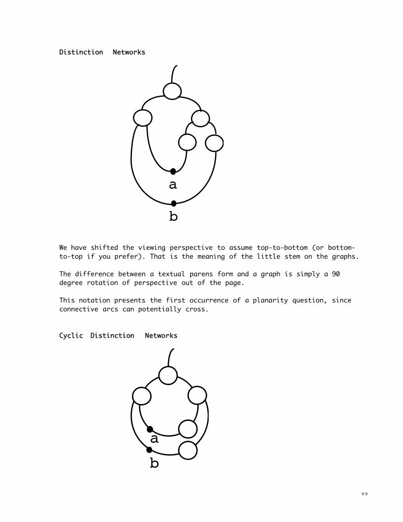
Distinction Networks
a
b
We have shifted the viewing perspective to assume top-to-bottom (or bottom-
to-top if you prefer). That is the meaning of the little stem on the graphs.
The difference between a textual parens form and a graph is simply a 90
degree rotation of perspective out of the page.
This notation presents the first occurrence of a planarity question, since
connective arcs can potentially cross.
Cyclic Distinction Networks
a
b

23
Flow is implicitly down in cycles, with overlaying of curves setting
ordering.
The main connectives (NOT, OR, NOT-NOT, AND):
a
a b
a b
a b

24
MAPS
Distinction Steps
b a
b a
Graphs are viewed from outside, using a external to the representation point-
of-view. Maps can be viewed from the inside, since the location of the
point-of-view determines the meaning of the logic map.
They do not support commutativity.

25
The main connectives (NOT, OR, NOT-NOT, AND):
a
ba
ba
ba

26
Blobby Distinction Maps
a
b
Circular Distinction Maps
b
a

27
Rectangular Distinction Maps
ab
Distinction Rooms
ab
The main connectives (NOT, OR, AND):
a
a b
a b

28
Centered Distinction Steps
a b
The perspective-location dot is not strictly necessary, however in the
following, we abandon depth cues.
Centered Circular Distinction Maps
This notation moves from conventional perspective to none,
ba ba

29
Centered Rectangular Distinction Maps
Giving up the visual overlap cue of circular forms:
a b
BLOCKS
Parens Extruded Upward
( ) ( )( ) a b ( )( ) a b
Stacked Distinctions
a b
a b
Assumed top-to-bottom.

30
Distinction Walls
a
b
Single objects begin to remove the top-to-bottom assumption.
Distinction Blocks
a b
ba
The main connectives (NOT, OR, AND):
a
ba
ba

31
PATHS
Bar Trees
a bb a
Bar Graphs
Do not support commutativity
b
a

32
Path Graphs
a
b
Distinction Paths
a b

33
The main connectives (NOT, OR, AND):
a
a b
a b

34
NONSYMBOLIC LOGIC TRANSFORMATION TOOLS
Modern Tools
Natural Deduction
Resolution
Logic State Machines
Boolean Cubes
Matrices
Lattices
Computers
Logic Networks
Switching Circuits
Circuit Schematics
Transistor Networks
MODERN TOOLS
Axiomatic Systems
1847 DeMorgan
1854 Boole
1879 Frege
c1880 Peirce
1881 Venn
1894 Peano
1904 Huntington
1910 Russell
1913 Sheffer
1917 Nicod
1921 Wittgenstein
1924 Schonfinkel
1927 vonNeumann
1930 Lukasiewicz
1933 Huntington
1934 Hilbert and Bernays
1934 Carnap
1934 Gentzen
Natural Deduction
In the following spatial notation, [P] means "suppose that P is TRUE"
The bottom of each notational grouping supports the Top, traveling down is
deduction.
Natural deduction has balanced rules for introducing and eliminating signs.

35
P Q P&Q P&Q
----- --- ---
P&Q P Q
P Q
--- ---
PvQ PvQ
[P] [Q]
PvQ Q R
-------------
R
[P]
FALSE P ¬P ¬¬P FALSE
----- ------- --- -----
¬P FALSE P P
[P]
Q P P->Q
---- ---------
P->Q Q
Proof Steps in Natural Deduction
Logical proof using natural deduction consists of creating a list of
justified steps. Since the results from any prior step may be called upon in
a following step, the steps themselves are not a linear ordering, but rather
they are a spatial array.
Premise: ((a OR b) AND ((NOT a) OR (NOT b)))
Conclusion: (NOT ((IF a b) AND (IF b a)))

36
------
1. ((IF a b) AND (IF b a))) indirect proof, assumption
2. (IF a b) simplification 1
---
3. a indirect proof, assumption
4. b modus ponens 2,3
5. (a AND b) conjunction 3,4
6. (NOT ((NOT a) OR (NOT b))) DeMorgan 5
7. ((NOT a) OR (NOT b)) simplification, premise
8. (NOT ((NOT a) OR (NOT b)))
AND ((NOT a) OR (NOT b)) conjunction 6,7
9. (NOT a) contradiction 3,8
---
10. (IF b a) simplification 1
11. (IF (NOT a) (NOT b)) contraposition 10
12. (NOT b) modus ponens 9,11
13. (a OR b) simplification, premise
14. a disjunctive syllogism 12,13
15. a AND (NOT a) conjunction 9,14
16. (NOT ((IF a b) AND (IF b a))) contradiction 1,15 QED.
------
In recognition of the non-linear structure of proofs, logicians use a tree
format for display which highlights the partial ordering between premises and
conclusion. Conversion of sequential display into tree form is called
"resolution into proof threads". The above proof
[16]
[15][1]*
[7]
[9]
[3]* [8]
P
[4]
[3]*
[6]
[5]
[3]*
[1]*
[2]
[14]
[11]
[13]
[10]
[12]
[1]*
[9] P

37
Resolution
In 1965, John Robinson devised a computational approach to proof called
resolution. The resolution principle uses the two possible cases of one
variable. If the fact that a thing is True leads to one conclusion, and the
fact that it is False leads to another conclusion, then in any case either
the first or the second conclusion is True.
((if P then Q) and (if (not P) then R)) implies (Q or R)
As a deductive rule, resolution can be stated in increasing general forms:
P and ¬P or False |= False
P and ¬P or Q |= Q
P or Q and ¬P or Q |= Q
P or Q and ¬P or R |= Q or R
(P and U) or Q and..(¬P and V) or R |= (U or Q) or (V or R)
Resolution proof uses a clausal data structure consisting of sets of
literals in disjunction. A pair of sets, one with a positive occurrence of a
variable and one with a negative occurrence, is resolved by forming the union
of the two sets, and deleting the resolvent variable.
{p, q} union {¬p, r} |= {q, r}
Facts are expressed as a singular set:
{p}
Rules are converted from implicational form to disjunctive form:
p -> q ==> ¬p or q ==> {¬p, q}
When the resolvent atoms have internal structure (functions and relations),
the internal variables are unified in the course of resolving the atoms.
Resolution expresses Boolean functions as sets of literals. This is a
different way to express CNF. The disjunctive forms in each clause form a
set with implicit disjunction. Each clause forms a different set.
Literals: atoms and negated atoms
Clauses: sets of literals joined by OR

38
The Resolution Rule
Let S1 and S2 be sets of clauses, and U be the set Union operator:
({a,b,...} U S1) & ({¬a,b,...} U S2) ==> {b,...} U S1 U S2
E.g.: {x,b,¬c} & {¬x,b,d} ==> {b,¬c,d} resolve on x.
Termination
{a} & {¬a} ==> { } ==> False
{a,¬a} ==> True
Not complete
¬{¬a,¬b} & { } ==> no action
Logic State Machines
TRUE
FALSE
Two objects, 16 ways to connect with presence or absence of directional
arrows.
Boolean Cubes
A Boolean function can be expressed in terms of a collection of vertices of a
hypercube (this is not the same use as the lattice hypercube). The set of
all Boolean functions of N variables is defined by all the possible
collections (the power set) of vertices (called ccubes).
Each cube is the conjunction of unique literals, one from each variable. The
whole is formed by the disjunction of all cubes.

39
Examples:
a ¬a
1 variable •---•
a&b a&¬b
2 variables •---•
| |
•---•
¬a&b ¬a&¬b
Boolean Cube Operations
Cubes can be used for computation, either symbolically or physically.
function = set of cubes
not function = set of cubes not in function
f or g = overlay the cubes of f and the cubes of g
f and g = intersect the cubes of f and the cubes of g
b
a
a'
b'a AND b
a' AND b'
Matrix Logic
10
1 0

40
By arranging the truth table of a Boolean function in a matrix form, the
rules of logic can be converted into the rules of matrix algebra. The
general format is:
BB
T F
T • •
AA
F •• •
Some examples:
A & B A v B A = B A->B A ¬A T
1 0 1 1 1 0 1 0 1 1 0 0 1 1
0 0 1 0 0 1 1 1 0 0 1 1 1 1
Each Boolean matrix is an operator. That is, in this formulation, there are
no objects. When using binary operations, matrix addition is xor; matrix
multiplication is and.
a + b = c a * b = c
0 + 0 = 0 0 * 0 = 0
0 + 1 = 1 0 * 1 = 0
1 + 0 = 1 1 * 0 = 0
1 + 1 = 0 1 * 1 = 1
xor and
Note that these relations are the same ones that apply to computational
addition.
As well, some matrix combinations result in matrices which are not Boolean
functions. This then extends Boolean operations into generally unexplored
territory, imaginary Boolean operations. Some examples of translating
between operators:

41
a + ¬a = T 1 1 + 0 0 = 1 1
0 0 1 1 1 1
a * ¬a = a 1 1 * 0 0 = 1 1
0 0 1 1 0 0
xor + and = or 0 1 + 1 0 = 1 1
1 0 0 0 1 0
nor^2 = nor 0 0 * 0 0 = 0 0
0 1 0 1 0 1
xor^2 = equal 0 1 * 0 1 = 1 0
(square-root of equal) 1 0 1 0 0 1
and + or = ? 1 0 + 1 1 = 2 1
0 0 1 0 1 0
Lattices
A lattice is a directed graph with links representing an ordering relation.
Lattices can have a maximal and a minimal element
( ) maximal
|
( )
| > greater than
( )
|
( ) minimal
A partial ordering uses the ordering relation greater-than-or-equal-
to.
( ) maximal
/ \
(1) (2) 1 = 2
\ /
( ) minimal

42
Hasse Diagrams (aka lattices)
A set and an ordering relation {S,>}, such that
• each object is a vertex
• if (a > b), then a is higher than b.
• if there is no c such that (a > c > b), then a is connected to b.
(a) (b) no maximal element
\ /
(c) (a>c) & (b>c) & (c>d)
|
(d) minimal
Boolean Hypercube
A distributed, complemented lattice. Two lattice combinational operations,
meet (follow any two lines down) and join (follow any two up).
For a Boolean interpretation, join = AND, meet = OR
Tells all structural relations between different binary logic operators.
TRUE
FALSE
XOR IFF
NOR
NAND
NIF B
IF A
NIF AAND
OR IF B
NOT BNOT ABA

43
COMPUTERS
Logic Networks
bXOR
a
Switching Circuits
a
b
a
b

44
Circuit Schematics
a
b
a
b
a
b
a
b

45
Transistor Networks
+V
a XOR b
b
a

46
DIAGRAMMATIC PROOF FAMILIES
The following are proof families of representations
Boolean Cubes
Circuit Schematics
Parens
Enclosing Circles
Distinction Networks
Distinction Steps
Distinction Rooms
Distinction Blocks
Bar Graphs
Distinction Paths
AXIOMATIC EQUIVALENCE
The various sets of axioms are all equivalent in that they all express what
we have been calling primary logic. We have selected the parens form using
the computational axioms of boundary logic to demonstrate a common basis of
them all. Below, the modus ponens theorem (axiom) of conventional logic is
proved using each of the spatial representations. We assume that only their
computational axioms will be used.
AXIOMS
OCCLUSION (( ) A) = <void>
PERVASION A (A B) = A (B)
INVOLUTION ((A)) = A (actually a theorem)
PROOF OF MODUS PONENS
( ((a) ((a) b)) ) b = ( )
(a*(a'+b))'+b
NOT (a AND (NOT a OR b)) OR b
Parens
( ((a) ((a) b)) ) b transcription
(a) ((a) b) b inv
(a) ( ) b per (a) b
( ) dom

47
Boolean Cubes
Constructive
a
NOT a
(NOT a OR b)
(a AND (NOT a OR b))
NOT (a AND (NOT a OR b))
NOT (a AND (NOT a OR b)) OR b
a
b
¬a
¬b
a
¬(a & (¬a v b))a & (¬a v b)
¬a v b¬a
¬(a & (¬a v b)) v b

48
Enclosing Circles
b
aab
b
a
b
Distinction Networks
a
b
a
b b
a
b
a
b
a
b
a
Distinction Steps
a
b
a
b
a
b
a
b b
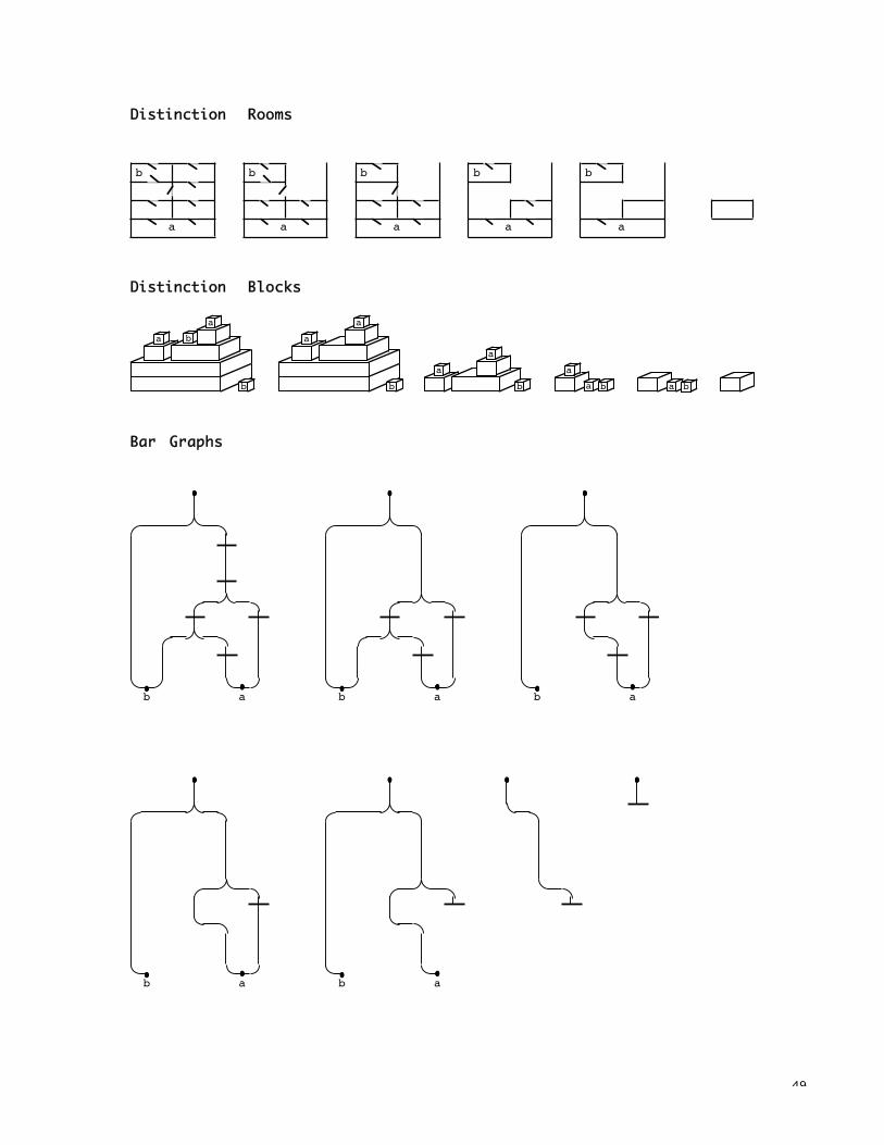
49
Distinction Rooms
a
b
a
b
a
b
a
b
a
b
Distinction Blocks
b
a
a
b
a
a
b
a
a
b
a
a b a b
Bar Graphs
b a b a b a
b a b a

50
Distinction Paths
a b a b a b
a b a b a b